JP2017015255A - Electro-hydrostatic actuator and hydraulic actuator control / damping method - Google Patents
Electro-hydrostatic actuator and hydraulic actuator control / damping method Download PDFInfo
- Publication number
- JP2017015255A JP2017015255A JP2016119441A JP2016119441A JP2017015255A JP 2017015255 A JP2017015255 A JP 2017015255A JP 2016119441 A JP2016119441 A JP 2016119441A JP 2016119441 A JP2016119441 A JP 2016119441A JP 2017015255 A JP2017015255 A JP 2017015255A
- Authority
- JP
- Japan
- Prior art keywords
- pump
- movable member
- flow path
- electric motor
- hydraulic
- Prior art date
- Legal status (The legal status is an assumption and is not a legal conclusion. Google has not performed a legal analysis and makes no representation as to the accuracy of the status listed.)
- Granted
Links
Images


Classifications
-
- B—PERFORMING OPERATIONS; TRANSPORTING
- B64—AIRCRAFT; AVIATION; COSMONAUTICS
- B64C—AEROPLANES; HELICOPTERS
- B64C13/00—Control systems or transmitting systems for actuating flying-control surfaces, lift-increasing flaps, air brakes, or spoilers
- B64C13/24—Transmitting means
- B64C13/38—Transmitting means with power amplification
- B64C13/50—Transmitting means with power amplification using electrical energy
- B64C13/504—Transmitting means with power amplification using electrical energy using electro-hydrostatic actuators [EHA's]
-
- B—PERFORMING OPERATIONS; TRANSPORTING
- B64—AIRCRAFT; AVIATION; COSMONAUTICS
- B64C—AEROPLANES; HELICOPTERS
- B64C13/00—Control systems or transmitting systems for actuating flying-control surfaces, lift-increasing flaps, air brakes, or spoilers
- B64C13/24—Transmitting means
- B64C13/26—Transmitting means without power amplification or where power amplification is irrelevant
- B64C13/28—Transmitting means without power amplification or where power amplification is irrelevant mechanical
- B64C13/341—Transmitting means without power amplification or where power amplification is irrelevant mechanical having duplication or stand-by provisions
-
- B—PERFORMING OPERATIONS; TRANSPORTING
- B64—AIRCRAFT; AVIATION; COSMONAUTICS
- B64C—AEROPLANES; HELICOPTERS
- B64C13/00—Control systems or transmitting systems for actuating flying-control surfaces, lift-increasing flaps, air brakes, or spoilers
- B64C13/24—Transmitting means
- B64C13/38—Transmitting means with power amplification
- B64C13/40—Transmitting means with power amplification using fluid pressure
- B64C13/42—Transmitting means with power amplification using fluid pressure having duplication or stand-by provisions
-
- B—PERFORMING OPERATIONS; TRANSPORTING
- B64—AIRCRAFT; AVIATION; COSMONAUTICS
- B64C—AEROPLANES; HELICOPTERS
- B64C13/00—Control systems or transmitting systems for actuating flying-control surfaces, lift-increasing flaps, air brakes, or spoilers
- B64C13/24—Transmitting means
- B64C13/38—Transmitting means with power amplification
- B64C13/50—Transmitting means with power amplification using electrical energy
- B64C13/505—Transmitting means with power amplification using electrical energy having duplication or stand-by provisions
-
- F—MECHANICAL ENGINEERING; LIGHTING; HEATING; WEAPONS; BLASTING
- F04—POSITIVE - DISPLACEMENT MACHINES FOR LIQUIDS; PUMPS FOR LIQUIDS OR ELASTIC FLUIDS
- F04B—POSITIVE-DISPLACEMENT MACHINES FOR LIQUIDS; PUMPS
- F04B1/00—Multi-cylinder machines or pumps characterised by number or arrangement of cylinders
- F04B1/12—Multi-cylinder machines or pumps characterised by number or arrangement of cylinders having cylinder axes coaxial with, or parallel or inclined to, main shaft axis
- F04B1/122—Details or component parts, e.g. valves, sealings or lubrication means
-
- F—MECHANICAL ENGINEERING; LIGHTING; HEATING; WEAPONS; BLASTING
- F04—POSITIVE - DISPLACEMENT MACHINES FOR LIQUIDS; PUMPS FOR LIQUIDS OR ELASTIC FLUIDS
- F04B—POSITIVE-DISPLACEMENT MACHINES FOR LIQUIDS; PUMPS
- F04B1/00—Multi-cylinder machines or pumps characterised by number or arrangement of cylinders
- F04B1/12—Multi-cylinder machines or pumps characterised by number or arrangement of cylinders having cylinder axes coaxial with, or parallel or inclined to, main shaft axis
- F04B1/14—Multi-cylinder machines or pumps characterised by number or arrangement of cylinders having cylinder axes coaxial with, or parallel or inclined to, main shaft axis having stationary cylinders
- F04B1/141—Details or component parts
- F04B1/143—Cylinders
-
- F—MECHANICAL ENGINEERING; LIGHTING; HEATING; WEAPONS; BLASTING
- F04—POSITIVE - DISPLACEMENT MACHINES FOR LIQUIDS; PUMPS FOR LIQUIDS OR ELASTIC FLUIDS
- F04B—POSITIVE-DISPLACEMENT MACHINES FOR LIQUIDS; PUMPS
- F04B1/00—Multi-cylinder machines or pumps characterised by number or arrangement of cylinders
- F04B1/12—Multi-cylinder machines or pumps characterised by number or arrangement of cylinders having cylinder axes coaxial with, or parallel or inclined to, main shaft axis
- F04B1/14—Multi-cylinder machines or pumps characterised by number or arrangement of cylinders having cylinder axes coaxial with, or parallel or inclined to, main shaft axis having stationary cylinders
- F04B1/141—Details or component parts
- F04B1/145—Housings
-
- F—MECHANICAL ENGINEERING; LIGHTING; HEATING; WEAPONS; BLASTING
- F04—POSITIVE - DISPLACEMENT MACHINES FOR LIQUIDS; PUMPS FOR LIQUIDS OR ELASTIC FLUIDS
- F04B—POSITIVE-DISPLACEMENT MACHINES FOR LIQUIDS; PUMPS
- F04B1/00—Multi-cylinder machines or pumps characterised by number or arrangement of cylinders
- F04B1/12—Multi-cylinder machines or pumps characterised by number or arrangement of cylinders having cylinder axes coaxial with, or parallel or inclined to, main shaft axis
- F04B1/14—Multi-cylinder machines or pumps characterised by number or arrangement of cylinders having cylinder axes coaxial with, or parallel or inclined to, main shaft axis having stationary cylinders
- F04B1/141—Details or component parts
- F04B1/146—Swash plates; Actuating elements
-
- F—MECHANICAL ENGINEERING; LIGHTING; HEATING; WEAPONS; BLASTING
- F04—POSITIVE - DISPLACEMENT MACHINES FOR LIQUIDS; PUMPS FOR LIQUIDS OR ELASTIC FLUIDS
- F04B—POSITIVE-DISPLACEMENT MACHINES FOR LIQUIDS; PUMPS
- F04B1/00—Multi-cylinder machines or pumps characterised by number or arrangement of cylinders
- F04B1/12—Multi-cylinder machines or pumps characterised by number or arrangement of cylinders having cylinder axes coaxial with, or parallel or inclined to, main shaft axis
- F04B1/20—Multi-cylinder machines or pumps characterised by number or arrangement of cylinders having cylinder axes coaxial with, or parallel or inclined to, main shaft axis having rotary cylinder block
-
- F—MECHANICAL ENGINEERING; LIGHTING; HEATING; WEAPONS; BLASTING
- F04—POSITIVE - DISPLACEMENT MACHINES FOR LIQUIDS; PUMPS FOR LIQUIDS OR ELASTIC FLUIDS
- F04B—POSITIVE-DISPLACEMENT MACHINES FOR LIQUIDS; PUMPS
- F04B17/00—Pumps characterised by combination with, or adaptation to, specific driving engines or motors
- F04B17/03—Pumps characterised by combination with, or adaptation to, specific driving engines or motors driven by electric motors
-
- F—MECHANICAL ENGINEERING; LIGHTING; HEATING; WEAPONS; BLASTING
- F04—POSITIVE - DISPLACEMENT MACHINES FOR LIQUIDS; PUMPS FOR LIQUIDS OR ELASTIC FLUIDS
- F04B—POSITIVE-DISPLACEMENT MACHINES FOR LIQUIDS; PUMPS
- F04B49/00—Control, e.g. of pump delivery, or pump pressure of, or safety measures for, machines, pumps, or pumping installations, not otherwise provided for, or of interest apart from, groups F04B1/00 - F04B47/00
- F04B49/22—Control, e.g. of pump delivery, or pump pressure of, or safety measures for, machines, pumps, or pumping installations, not otherwise provided for, or of interest apart from, groups F04B1/00 - F04B47/00 by means of valves
- F04B49/24—Bypassing
-
- F—MECHANICAL ENGINEERING; LIGHTING; HEATING; WEAPONS; BLASTING
- F15—FLUID-PRESSURE ACTUATORS; HYDRAULICS OR PNEUMATICS IN GENERAL
- F15B—SYSTEMS ACTING BY MEANS OF FLUIDS IN GENERAL; FLUID-PRESSURE ACTUATORS, e.g. SERVOMOTORS; DETAILS OF FLUID-PRESSURE SYSTEMS, NOT OTHERWISE PROVIDED FOR
- F15B11/00—Servomotor systems without provision for follow-up action; Circuits therefor
- F15B11/02—Systems essentially incorporating special features for controlling the speed or actuating force of an output member
- F15B11/024—Systems essentially incorporating special features for controlling the speed or actuating force of an output member by means of differential connection of the servomotor lines, e.g. regenerative circuits
-
- F—MECHANICAL ENGINEERING; LIGHTING; HEATING; WEAPONS; BLASTING
- F15—FLUID-PRESSURE ACTUATORS; HYDRAULICS OR PNEUMATICS IN GENERAL
- F15B—SYSTEMS ACTING BY MEANS OF FLUIDS IN GENERAL; FLUID-PRESSURE ACTUATORS, e.g. SERVOMOTORS; DETAILS OF FLUID-PRESSURE SYSTEMS, NOT OTHERWISE PROVIDED FOR
- F15B20/00—Safety arrangements for fluid actuator systems; Applications of safety devices in fluid actuator systems; Emergency measures for fluid actuator systems
- F15B20/002—Electrical failure
-
- F—MECHANICAL ENGINEERING; LIGHTING; HEATING; WEAPONS; BLASTING
- F15—FLUID-PRESSURE ACTUATORS; HYDRAULICS OR PNEUMATICS IN GENERAL
- F15B—SYSTEMS ACTING BY MEANS OF FLUIDS IN GENERAL; FLUID-PRESSURE ACTUATORS, e.g. SERVOMOTORS; DETAILS OF FLUID-PRESSURE SYSTEMS, NOT OTHERWISE PROVIDED FOR
- F15B7/00—Systems in which the movement produced is definitely related to the output of a volumetric pump; Telemotors
- F15B7/005—With rotary or crank input
- F15B7/006—Rotary pump input
-
- F—MECHANICAL ENGINEERING; LIGHTING; HEATING; WEAPONS; BLASTING
- F15—FLUID-PRESSURE ACTUATORS; HYDRAULICS OR PNEUMATICS IN GENERAL
- F15B—SYSTEMS ACTING BY MEANS OF FLUIDS IN GENERAL; FLUID-PRESSURE ACTUATORS, e.g. SERVOMOTORS; DETAILS OF FLUID-PRESSURE SYSTEMS, NOT OTHERWISE PROVIDED FOR
- F15B11/00—Servomotor systems without provision for follow-up action; Circuits therefor
- F15B11/02—Systems essentially incorporating special features for controlling the speed or actuating force of an output member
- F15B11/024—Systems essentially incorporating special features for controlling the speed or actuating force of an output member by means of differential connection of the servomotor lines, e.g. regenerative circuits
- F15B2011/0243—Systems essentially incorporating special features for controlling the speed or actuating force of an output member by means of differential connection of the servomotor lines, e.g. regenerative circuits the regenerative circuit being activated or deactivated automatically
-
- F—MECHANICAL ENGINEERING; LIGHTING; HEATING; WEAPONS; BLASTING
- F15—FLUID-PRESSURE ACTUATORS; HYDRAULICS OR PNEUMATICS IN GENERAL
- F15B—SYSTEMS ACTING BY MEANS OF FLUIDS IN GENERAL; FLUID-PRESSURE ACTUATORS, e.g. SERVOMOTORS; DETAILS OF FLUID-PRESSURE SYSTEMS, NOT OTHERWISE PROVIDED FOR
- F15B2211/00—Circuits for servomotor systems
- F15B2211/20—Fluid pressure source, e.g. accumulator or variable axial piston pump
- F15B2211/205—Systems with pumps
- F15B2211/20507—Type of prime mover
- F15B2211/20515—Electric motor
-
- F—MECHANICAL ENGINEERING; LIGHTING; HEATING; WEAPONS; BLASTING
- F15—FLUID-PRESSURE ACTUATORS; HYDRAULICS OR PNEUMATICS IN GENERAL
- F15B—SYSTEMS ACTING BY MEANS OF FLUIDS IN GENERAL; FLUID-PRESSURE ACTUATORS, e.g. SERVOMOTORS; DETAILS OF FLUID-PRESSURE SYSTEMS, NOT OTHERWISE PROVIDED FOR
- F15B2211/00—Circuits for servomotor systems
- F15B2211/20—Fluid pressure source, e.g. accumulator or variable axial piston pump
- F15B2211/205—Systems with pumps
- F15B2211/2053—Type of pump
- F15B2211/20561—Type of pump reversible
-
- F—MECHANICAL ENGINEERING; LIGHTING; HEATING; WEAPONS; BLASTING
- F15—FLUID-PRESSURE ACTUATORS; HYDRAULICS OR PNEUMATICS IN GENERAL
- F15B—SYSTEMS ACTING BY MEANS OF FLUIDS IN GENERAL; FLUID-PRESSURE ACTUATORS, e.g. SERVOMOTORS; DETAILS OF FLUID-PRESSURE SYSTEMS, NOT OTHERWISE PROVIDED FOR
- F15B2211/00—Circuits for servomotor systems
- F15B2211/20—Fluid pressure source, e.g. accumulator or variable axial piston pump
- F15B2211/27—Directional control by means of the pressure source
-
- F—MECHANICAL ENGINEERING; LIGHTING; HEATING; WEAPONS; BLASTING
- F15—FLUID-PRESSURE ACTUATORS; HYDRAULICS OR PNEUMATICS IN GENERAL
- F15B—SYSTEMS ACTING BY MEANS OF FLUIDS IN GENERAL; FLUID-PRESSURE ACTUATORS, e.g. SERVOMOTORS; DETAILS OF FLUID-PRESSURE SYSTEMS, NOT OTHERWISE PROVIDED FOR
- F15B2211/00—Circuits for servomotor systems
- F15B2211/30—Directional control
- F15B2211/305—Directional control characterised by the type of valves
- F15B2211/3056—Assemblies of multiple valves
- F15B2211/30565—Assemblies of multiple valves having multiple valves for a single output member, e.g. for creating higher valve function by use of multiple valves like two 2/2-valves replacing a 5/3-valve
- F15B2211/3058—Assemblies of multiple valves having multiple valves for a single output member, e.g. for creating higher valve function by use of multiple valves like two 2/2-valves replacing a 5/3-valve having additional valves for interconnecting the fluid chambers of a double-acting actuator, e.g. for regeneration mode or for floating mode
-
- F—MECHANICAL ENGINEERING; LIGHTING; HEATING; WEAPONS; BLASTING
- F15—FLUID-PRESSURE ACTUATORS; HYDRAULICS OR PNEUMATICS IN GENERAL
- F15B—SYSTEMS ACTING BY MEANS OF FLUIDS IN GENERAL; FLUID-PRESSURE ACTUATORS, e.g. SERVOMOTORS; DETAILS OF FLUID-PRESSURE SYSTEMS, NOT OTHERWISE PROVIDED FOR
- F15B2211/00—Circuits for servomotor systems
- F15B2211/30—Directional control
- F15B2211/315—Directional control characterised by the connections of the valve or valves in the circuit
- F15B2211/31523—Directional control characterised by the connections of the valve or valves in the circuit being connected to a pressure source and an output member
- F15B2211/31529—Directional control characterised by the connections of the valve or valves in the circuit being connected to a pressure source and an output member having a single pressure source and a single output member
-
- F—MECHANICAL ENGINEERING; LIGHTING; HEATING; WEAPONS; BLASTING
- F15—FLUID-PRESSURE ACTUATORS; HYDRAULICS OR PNEUMATICS IN GENERAL
- F15B—SYSTEMS ACTING BY MEANS OF FLUIDS IN GENERAL; FLUID-PRESSURE ACTUATORS, e.g. SERVOMOTORS; DETAILS OF FLUID-PRESSURE SYSTEMS, NOT OTHERWISE PROVIDED FOR
- F15B2211/00—Circuits for servomotor systems
- F15B2211/30—Directional control
- F15B2211/32—Directional control characterised by the type of actuation
- F15B2211/327—Directional control characterised by the type of actuation electrically or electronically
-
- F—MECHANICAL ENGINEERING; LIGHTING; HEATING; WEAPONS; BLASTING
- F15—FLUID-PRESSURE ACTUATORS; HYDRAULICS OR PNEUMATICS IN GENERAL
- F15B—SYSTEMS ACTING BY MEANS OF FLUIDS IN GENERAL; FLUID-PRESSURE ACTUATORS, e.g. SERVOMOTORS; DETAILS OF FLUID-PRESSURE SYSTEMS, NOT OTHERWISE PROVIDED FOR
- F15B2211/00—Circuits for servomotor systems
- F15B2211/60—Circuit components or control therefor
- F15B2211/625—Accumulators
-
- F—MECHANICAL ENGINEERING; LIGHTING; HEATING; WEAPONS; BLASTING
- F15—FLUID-PRESSURE ACTUATORS; HYDRAULICS OR PNEUMATICS IN GENERAL
- F15B—SYSTEMS ACTING BY MEANS OF FLUIDS IN GENERAL; FLUID-PRESSURE ACTUATORS, e.g. SERVOMOTORS; DETAILS OF FLUID-PRESSURE SYSTEMS, NOT OTHERWISE PROVIDED FOR
- F15B2211/00—Circuits for servomotor systems
- F15B2211/60—Circuit components or control therefor
- F15B2211/665—Methods of control using electronic components
- F15B2211/6658—Control using different modes, e.g. four-quadrant-operation, working mode and transportation mode
-
- F—MECHANICAL ENGINEERING; LIGHTING; HEATING; WEAPONS; BLASTING
- F15—FLUID-PRESSURE ACTUATORS; HYDRAULICS OR PNEUMATICS IN GENERAL
- F15B—SYSTEMS ACTING BY MEANS OF FLUIDS IN GENERAL; FLUID-PRESSURE ACTUATORS, e.g. SERVOMOTORS; DETAILS OF FLUID-PRESSURE SYSTEMS, NOT OTHERWISE PROVIDED FOR
- F15B2211/00—Circuits for servomotor systems
- F15B2211/70—Output members, e.g. hydraulic motors or cylinders or control therefor
- F15B2211/705—Output members, e.g. hydraulic motors or cylinders or control therefor characterised by the type of output members or actuators
- F15B2211/7051—Linear output members
- F15B2211/7053—Double-acting output members
- F15B2211/7054—Having equal piston areas
-
- Y—GENERAL TAGGING OF NEW TECHNOLOGICAL DEVELOPMENTS; GENERAL TAGGING OF CROSS-SECTIONAL TECHNOLOGIES SPANNING OVER SEVERAL SECTIONS OF THE IPC; TECHNICAL SUBJECTS COVERED BY FORMER USPC CROSS-REFERENCE ART COLLECTIONS [XRACs] AND DIGESTS
- Y02—TECHNOLOGIES OR APPLICATIONS FOR MITIGATION OR ADAPTATION AGAINST CLIMATE CHANGE
- Y02T—CLIMATE CHANGE MITIGATION TECHNOLOGIES RELATED TO TRANSPORTATION
- Y02T50/00—Aeronautics or air transport
- Y02T50/40—Weight reduction
Landscapes
- Engineering & Computer Science (AREA)
- Mechanical Engineering (AREA)
- General Engineering & Computer Science (AREA)
- Physics & Mathematics (AREA)
- Fluid Mechanics (AREA)
- Aviation & Aerospace Engineering (AREA)
- Automation & Control Theory (AREA)
- Chemical & Material Sciences (AREA)
- Analytical Chemistry (AREA)
- Actuator (AREA)
- Reciprocating Pumps (AREA)
- Fluid-Pressure Circuits (AREA)
- Control Of Positive-Displacement Pumps (AREA)
- Magnetically Actuated Valves (AREA)
- Electromagnetic Pumps, Or The Like (AREA)
Abstract
Description
本開示は、電気静油圧アクチュエータに関し、特に、油圧アクチュエータの圧力・流量制御を行うために電動モーターポンプアセンブリを備える電気静油圧アクチュエータに関する。 The present disclosure relates to an electrohydrostatic actuator, and more particularly, to an electrohydrostatic actuator including an electric motor pump assembly for controlling pressure and flow rate of the hydraulic actuator.
電気静油圧アクチュエータ(EHA)は、独立型のアクチュエータとして動作するものであり、それ自体の電動モーターポンプアセンブリによって制御され、それによって独立した油圧ポンプが不要となる。航空宇宙用途では、EHAは通常、制御電子回路によって作動されるフライバイワイヤ(FBW)式の装置である。EHAの油圧アクチュエータは、航空機翼上の操縦フラップなどの空気力学的表面を移動させるために使用され得る。EHAは、例えば、ランディングギヤの伸縮、操縦、ブレーキ及び流量制御を含む各種操作のために、航空機における従来の油圧アクチュエータシステムに置き換わる場合がある。 The electrohydrostatic actuator (EHA) operates as a stand-alone actuator and is controlled by its own electric motor pump assembly, thereby eliminating the need for a separate hydraulic pump. In aerospace applications, EHA is typically a fly-by-wire (FBW) type device operated by control electronics. EHA hydraulic actuators can be used to move aerodynamic surfaces such as steering flaps on aircraft wings. The EHA may replace conventional hydraulic actuator systems in aircraft for various operations including, for example, landing gear expansion / contraction, steering, braking and flow control.
特に、航空機操作の構成要素を制御するのにEHAを用いるときには、発電が停止し、あるいは制御パスの電子回路が故障した場合に冗長性を持たせることが重要である。例えば、特許文献1に見られるように、EHAがフェイルセーフ油圧回路を備えるようにすることが従来提案されている。このフェイルセーフ油圧回路は、油圧アクチュエータのジャッキ室とソレノイド「モード」バルブとの間の連通を可能にする別の作動油経路を備えており、このバルブにより、例えば、停電した緊急状態において、別の作動油経路を接続するように切り替えることができ、電動油圧ポンプの外側を作動油が迂回して流れることが可能となる。かかる緊急状態では、油圧アクチュエータは、依然として、その空気力学的表面に減衰力を与えることが可能である。この減衰効果は、油圧回路内の別のソレノイドバルブによってオンまたはオフに切り替えられる。 In particular, when using EHA to control aircraft operating components, it is important to provide redundancy if power generation stops or the control path electronics fail. For example, as seen in Patent Document 1, it has been conventionally proposed that the EHA includes a fail-safe hydraulic circuit. This fail-safe hydraulic circuit has a separate hydraulic fluid path that allows communication between the jack chamber of the hydraulic actuator and the solenoid “mode” valve, which allows for separate operation, for example, in the event of a power failure. It is possible to switch so as to connect the hydraulic oil path, and the hydraulic oil can flow around the outside of the electric hydraulic pump. In such an emergency situation, the hydraulic actuator can still impart a damping force to its aerodynamic surface. This damping effect is switched on or off by another solenoid valve in the hydraulic circuit.
本開示は、電気静油圧アクチュエータに改善を施すことを図るものである。 The present disclosure is intended to improve an electrohydrostatic actuator.
本開示の態様によれば、電気静油圧アクチュエータ(EHA)が提供される。この電気静油圧アクチュエータは、油圧ポンプと、油圧ポンプを駆動して油圧アクチュエータに作動流体を供給する電気モーターと;作動流体の入口及び出口、並びに入口と出口の間に配置された能動的な流体流路を備える油圧ポンプであって、油圧ポンプが電気モーターによって駆動されている能動動作モード時に、作動流体が能動的に入口から吸入され、出口から吐出されるようにする油圧ポンプと;油圧ポンプの入口と出口の間に配置されたバイパス流路をさらに備える油圧ポンプであって、減衰動作モード時に、作動流体が入口と出口の間を両方向に自由に流れることを可能にする油圧ポンプと;電気モーター内で移動するように配置された可動部材を備える電気モーターであって、能動動作モード時には、油圧ポンプを駆動するように電気モーターが励磁されているときに、可動部材が、バイパス流路を閉塞するように機能する閉塞位置となり、減衰動作モード時には、電気モーターが励磁されていないときに、可動部材が電気モーター内で移動してバイパス流路を開放する電気モーターと、を備える。 According to aspects of the present disclosure, an electrohydrostatic actuator (EHA) is provided. The electrohydrostatic actuator includes a hydraulic pump, an electric motor that drives the hydraulic pump to supply a working fluid to the hydraulic actuator; an inlet and an outlet of the working fluid, and an active fluid disposed between the inlet and the outlet A hydraulic pump having a flow path, wherein the hydraulic fluid is actively sucked from the inlet and discharged from the outlet in an active operation mode in which the hydraulic pump is driven by an electric motor; A hydraulic pump further comprising a bypass flow path disposed between the inlet and the outlet of the hydraulic pump, allowing the working fluid to freely flow in both directions between the inlet and the outlet during the damping operation mode; An electric motor with a movable member arranged to move within the electric motor, which drives the hydraulic pump in the active mode of operation. When the electric motor is energized, the movable member is in a closed position that functions to close the bypass flow path. In the damping operation mode, the movable member is placed in the electric motor when the electric motor is not excited. And an electric motor that moves to open the bypass flow path.
能動動作モードでは、油圧ポンプが電気モーターによって駆動されているときに、EHAは、油圧アクチュエータの圧力・流量制御を行う油圧ポンプと共に正常に作動する。例えば、電気モーターが励磁されていないときには(例えば、停電が発生し、またはEHAの制御電子回路が故障した場合には)、バイパス流路によって作動流体が油圧ポンプを通過するようにして、油圧アクチュエータの減衰効果を実現することができる。これにより、油圧アクチュエータを能動的に連動させる必要のないときにデフォルトモードも提供される。油圧ポンプの入口と出口の間のバイパス流路を開放することにより、油圧ポンプと油圧アクチュエータの間の油圧回路に別のソレノイド「モード」バルブが必要となる代わりに、減衰動作モードがポンプに組み込まれる。これにより、装置を包絡線的に減衰させることが可能となるのみならず、EHA内の構成要素の数が削減される。例えば、EHAには、自らの電源及び制御電子回路を備えた別のソレノイドモードバルブ、並びにアンチキャビテーションバルブがもはや不要となり得る。従って、油圧マニホールドに必要な関連流路は、EHAのコスト及び重量の削減を伴って取り除かれる。さらに、かかるEHAでは、油圧ポンプモーターアセンブリに減衰制御が組み込まれるため、信頼性が向上し得る。 In the active operation mode, when the hydraulic pump is driven by an electric motor, the EHA operates normally together with the hydraulic pump that controls the pressure and flow rate of the hydraulic actuator. For example, when the electric motor is not energized (for example, when a power failure occurs or the control electronics of the EHA fails), the hydraulic fluid is passed through the hydraulic pump by the bypass flow path so that the hydraulic actuator The attenuation effect can be realized. This also provides a default mode when it is not necessary to actively engage the hydraulic actuator. By opening a bypass flow path between the inlet and outlet of the hydraulic pump, a damping mode of operation is built into the pump instead of requiring a separate solenoid “mode” valve in the hydraulic circuit between the hydraulic pump and the hydraulic actuator It is. This not only makes it possible to attenuate the device in an envelope manner, but also reduces the number of components in the EHA. For example, EHA may no longer require a separate solenoid mode valve with its own power supply and control electronics, and an anti-cavitation valve. Thus, the associated flow path required for the hydraulic manifold is eliminated with a reduction in EHA cost and weight. Further, such EHA can improve reliability because damping control is built into the hydraulic pump motor assembly.
油圧ポンプは、識別可能な入口及び出口を任意の時点で有するように記載されているものの、入口及び出口を提供する1つまたは複数の物理ポートは経時的に変わり得ることが理解されよう。記載されたポンプは、通常、油圧アクチュエータと流体連通している複数のポートを備える。任意の一時点において、これらのポートの1つまたは複数が入口として機能してもよく、これらのポートの1つまたは複数が出口として機能してもよい。かかるポート、すなわち入口及び出口は、通常、ポンプの基部に取り付けられているポートプレートによって提供される。回転ポンプの場合、モーターの回転方向が逆転すると、逆方向に作動流体を供給するようにポンプが作動し、入口と出口が入れ替わる場合がある。さらに、能動的な流路及びバイパス流路に関して入口及び出口のみを開示しているが、ポンプは、例えば、他の流路を提供する1つまたは複数の別の入口及び/または出口を備え得ることが可能である。例えば、非対称ポンプの場合、アキュムレータへの流体の流れを促進するために別の出口が存在し得る。 Although a hydraulic pump is described as having identifiable inlets and outlets at any point in time, it will be appreciated that the one or more physical ports providing the inlets and outlets may change over time. The described pump typically comprises a plurality of ports in fluid communication with a hydraulic actuator. At any one time, one or more of these ports may function as an inlet, and one or more of these ports may function as an outlet. Such ports, i.e., inlet and outlet, are usually provided by a port plate attached to the base of the pump. In the case of a rotary pump, when the rotation direction of the motor is reversed, the pump may be operated to supply the working fluid in the reverse direction, and the inlet and the outlet may be switched. Further, although only inlets and outlets are disclosed with respect to active and bypass channels, the pump may comprise, for example, one or more separate inlets and / or outlets that provide other channels. It is possible. For example, in the case of an asymmetric pump, another outlet may be present to facilitate fluid flow to the accumulator.
モーター内で移動するように配置された可動部材を回転自在に移動するように配置して、減衰動作モード時にバイパス流路を開放するようにしてもよい。しかしながら、好ましい一連の実施例では、可動部材は、モーター内で軸方向に移動してバイパス流路を開放するように配置されている。従って、可動部材は、閉塞位置との間で軸方向に移動し得る。 A movable member arranged to move in the motor may be arranged to move freely so that the bypass flow path is opened in the damping operation mode. However, in a preferred series of embodiments, the movable member is arranged to move axially within the motor to open the bypass flow path. Therefore, the movable member can move in the axial direction between the closed position.
可動部材がモーター内で軸方向に移動するように配置された実施例では、可動部材の軸方向移動はモーターの軸に沿うものと考えられる。モーターの軸は、通常、モーターシャフトがここを中心に回転する軸として定められる。モーターシャフトは、モーターの構成要素であり、このモーターは通常、能動モード時にポンプを駆動する。 In embodiments where the movable member is arranged to move axially within the motor, the axial movement of the movable member is considered to be along the axis of the motor. The axis of the motor is usually defined as the axis around which the motor shaft rotates. The motor shaft is a component of the motor, which normally drives the pump when in active mode.
モーターは、能動動作モード時にバイパス流路を閉塞する任意の適切な可動部材を備え得る。好ましい一連の実施例では、可動部材は細長い棒である。かかる細長い棒は、モーターシャフトを通ってポンプにまで、主モーターのハウジングから伸びてもよく、このハウジングには通常、モーターを駆動するコイルが収納される。細長い棒は、例えば、モーターシャフトの中空芯を貫通して油圧ポンプに達し得る。さらに好ましい一連の実施例では、細長い棒はさらに、バイパス流路に近接した末端にて、バイパス流路を閉塞するように形成された端部を備える。この端部は、例えば、バイパス流路を閉塞するように設計されたディスク形状部で構成されてもよい。バイパス流路を閉塞する細長い棒を使用することは有利である。というのも、この細長い棒は、バイパス流路を制御するための簡単な機構となるためである。かかる細長い棒を、閉塞位置との間で回転させてもよく、あるいは軸方向に移動させてもよい。 The motor may include any suitable movable member that occludes the bypass flow path during the active mode of operation. In a preferred series of embodiments, the movable member is an elongated bar. Such an elongated bar may extend from the housing of the main motor through the motor shaft to the pump, which usually contains a coil that drives the motor. The elongate bar can, for example, penetrate the hollow core of the motor shaft to reach the hydraulic pump. In a further preferred series of embodiments, the elongate bar further comprises an end formed to occlude the bypass channel at a distal end proximate to the bypass channel. This end may be constituted by, for example, a disk-shaped part designed to close the bypass flow path. It is advantageous to use an elongated bar that closes the bypass channel. This is because the elongated bar provides a simple mechanism for controlling the bypass flow path. Such an elongate bar may be rotated between closed positions or moved axially.
EHAは、電気モーターが励磁されているときにバイパス流路を閉塞するように可動部材を配置する任意の適切な機構を備え得る。電気モーターは、可動部材を閉塞位置に保持する電磁石機構を備え得る。通常、電気モーターは、モーターシャフトの周囲に電機子を形成するコイルを備える。一連の実施例では、この電磁石機構は、可動部材を励磁するように配置された1つまたは複数の追加コイルを備える。かかる一連の実施例では、モーターが励磁されているとき、これらの追加コイルに近接した可動部材の一部が励磁される。モーターは、好ましくは、1つまたは複数の固定された強磁性部を備えており、その結果、磁化された可動部材がこの強磁性部に引き寄せられる。これにより、バイパス流路を閉塞するように可動部材が閉塞位置に保持される。さらに好ましい一連の実施例では、追加コイルに近接した可動部材の端部が、磁化材料の最大領域となるように形成される。追加コイルが励磁されているときには、上記により、可動部材がその閉塞位置に確実に保持されることが保証される。好ましい一連の実施例では、可動部材の保持に用いられる追加コイルの数は、モーターの駆動に用いられるコイルの数と同じである。しかしながら、モーターの駆動に3つの主コイルが用いられる場合でも、追加コイルは2つで足り得ることが分かっている。 The EHA may comprise any suitable mechanism that positions the movable member to close the bypass flow path when the electric motor is energized. The electric motor may include an electromagnet mechanism that holds the movable member in the closed position. Usually, an electric motor comprises a coil that forms an armature around a motor shaft. In a series of embodiments, the electromagnet mechanism includes one or more additional coils arranged to excite the movable member. In such a series of embodiments, when the motor is energized, a portion of the movable member proximate to these additional coils is energized. The motor preferably comprises one or more fixed ferromagnetic parts so that the magnetized movable member is attracted to this ferromagnetic part. Thereby, the movable member is held at the closed position so as to close the bypass flow path. In a further preferred series of embodiments, the end of the movable member proximate the additional coil is formed to be the largest region of magnetized material. When the additional coil is energized, the above ensures that the movable member is securely held in its closed position. In a preferred series of embodiments, the number of additional coils used to hold the movable member is the same as the number of coils used to drive the motor. However, it has been found that two additional coils may be sufficient even when three main coils are used to drive the motor.
追加コイルは、主モーターコイル(例えば、モーターシャフトの周囲に電機子を形成するコイル)と直列または並列に接続され得る。EHAに追加コイルを設けて可動部材を励磁する実施例では、各追加コイルは、好ましくは、主モーターコイルの1つと直列に接続される。これにより、例えば、追加コイルの堅牢性に対する信頼が万一不足している場合に、フェイルセーフが提供される。というのも、追加コイルの1つに障害が発生すると主モーターの励磁回路が遮断されるためである。しかしながら、いくつかの実施例では、追加コイルを主モーターコイルと並列に接続してもよいことが理解される。これにより、追加コイルのうちの1つの障害によって開放回路が生じるリスクを軽減することができる。加えて、またはあるいは、いくつかの実施例では、追加コイルは、主モーターコイルと電源を共有してもよい。これは、電磁石機構がモーターと同時に自動的に励磁されること(例えば、モーターが励磁されるときには常に、電磁石機構によって可動部材がその閉塞位置に保持され得ること)を意味する。他の実施例では、追加コイルは、それ自体の独立電源を備えてもよい。例えば、追加コイルを作動させるために同じ交流電源を用いる際の安定性に対する信頼が低い場合に、この手法をとる場合がある。さらに、これは、例えば、主モーターコイルの停電が発生した場合に、可動部材の移動を独立に制御することが可能となり得ることを意味する。かかる実施例では、1つの追加コイルで十分となり得る。ただし、その追加コイルには、独立電源への配線を追加する必要がある。 The additional coil may be connected in series or in parallel with the main motor coil (eg, a coil that forms an armature around the motor shaft). In embodiments where an additional coil is provided on the EHA to excite the movable member, each additional coil is preferably connected in series with one of the main motor coils. Thereby, for example, when the reliability of the robustness of the additional coil is insufficient, fail-safe is provided. This is because the excitation circuit of the main motor is interrupted when a failure occurs in one of the additional coils. However, it will be appreciated that in some embodiments, an additional coil may be connected in parallel with the main motor coil. This can reduce the risk of an open circuit due to a failure in one of the additional coils. Additionally or alternatively, in some embodiments, the additional coil may share a power source with the main motor coil. This means that the electromagnet mechanism is automatically energized simultaneously with the motor (for example, whenever the motor is energized, the movable member can be held in its closed position by the electromagnet mechanism). In other embodiments, the additional coil may comprise its own independent power source. For example, this approach may be taken when the reliability of stability when using the same AC power source to activate the additional coil is low. Furthermore, this means that it may be possible to control the movement of the movable member independently, for example, when a main motor coil power failure occurs. In such an embodiment, one additional coil may be sufficient. However, it is necessary to add wiring to the independent power source for the additional coil.
一連の実施例では、ポンプが能動動作モードであるときに可動部材は回転しない。別の一連の実施例では、可動部材は、能動動作モード時にモーターシャフトと共に回転する。可動部材を回転させることにより、ポンプの製造がより簡単となり得る。というのも、これは、可動部材とモーターシャフトなどのモーターの回転部品との間にベアリングが必要ないことを意味するためである。 In a series of embodiments, the movable member does not rotate when the pump is in the active mode of operation. In another series of embodiments, the movable member rotates with the motor shaft during the active mode of operation. By rotating the movable member, the manufacture of the pump can be made easier. This is because it means that no bearing is required between the movable member and the rotating part of the motor such as the motor shaft.
前述のように、例えば、モーターが励磁されていないときには、バイパス流路が開放される。勿論、バイパス流路は、ポンプが電気モーターによって駆動されていないときにのみ完全に形成される流路の形態をとってもよい。あるいは、バイパス流路は、常にポンプの中に存在するものの、電気モーターが励磁されていないときには、単に、閉塞が解除される、遮蔽されない、アクセスが可能であるといった流路の形態をとってもよい。電気モーターがオフになったとき、あるいは停電があったときには、制御電子回路は、バイパス流路の開放を実施することができる。しかしながら、これには、かかる制御電子回路用の予備電源が必要となる可能性がある。電気モーターが励磁されていないときには、可動部材が自動的に移動してバイパス流路を開放することが好ましい。これにより、ポンプの外部のソレノイドバルブが不要となるのみならず、減衰動作モードを制御するためのフェイルセーフ電源も不要となる。むしろ、電気モーターが作動していないときには常に、減衰動作モードがデフォルトモードとしてポンプによって自動的に提供される。 As described above, for example, when the motor is not excited, the bypass flow path is opened. Of course, the bypass channel may take the form of a channel that is completely formed only when the pump is not driven by an electric motor. Alternatively, the bypass flow path may always be in the pump, but when the electric motor is not energized, it may simply take the form of a flow path that is unblocked, unshielded, or accessible. When the electric motor is turned off or when there is a power failure, the control electronics can perform the opening of the bypass flow path. However, this may require a reserve power supply for such control electronics. When the electric motor is not excited, it is preferable that the movable member automatically moves to open the bypass passage. This eliminates the need for a solenoid valve external to the pump, and also eliminates the need for a fail-safe power source for controlling the damping operation mode. Rather, the damping mode of operation is automatically provided by the pump as the default mode whenever the electric motor is not operating.
EHAは、電気モーターが励磁されていないときに可動部材を自動的に移動させる任意の適切な機構を備え得る。例えば、弾性部材は、バイパス流路の閉塞を解除する、またはバイパス流路を開放する位置にまで可動部材を付勢するように機能することが可能である。好ましい実施例では、ポンプは、かかる弾性部材を備える。この弾性部材は、可動部材を移動させることにより、電気モーターが励磁されていないときにバイパス流路を開放するように配置されている。弾性部材をポンプに配置することは有利である。というのも、これによってポンプに必要な変更が最小で済むためである。あるいは、弾性部材を、モーター内の任意の好適な位置に、例えば、モーターハウジングの中、またはモーターシャフトの中/表面に配置してもよい。ポンプから離して弾性部材を配置することは有利となり得る。というのも、バイパス流路に直接的な影響を及ぼさないように弾性部材を配置することが可能となるためである。例えば、ポンプ内の弾性部材により、バイパス流路が開放されているときでもバイパス流路を少なくとも部分的に遮断させるようにしてもよい。この構成は、いくつかの事例では不利となり得るが、かかる構成をバイパス流路の設計に取り入れることが可能になる場合がある。かかる弾性部材により、バイパス流路を開放するように可動部材を移動させやすくする弾性付勢が付与され得る。例えば、この弾性付勢は、ばね装置によって付与されてもよい。電気モーターが励磁されているときには、この弾性付勢に打ち勝つことができる。複数の弾性部材を使用することは有利となり得ることが理解される。というのも、これにより、たとえ1つの弾性部材が故障したとしても、EHAは、依然として減衰モードに入ることが確実に可能となるためである。これは特に、停電時に減衰モードが開始される場合に重要である。 The EHA may comprise any suitable mechanism that automatically moves the movable member when the electric motor is not energized. For example, the elastic member can function to release the blockage of the bypass flow path or bias the movable member to a position where the bypass flow path is opened. In a preferred embodiment, the pump comprises such an elastic member. The elastic member is arranged to open the bypass flow path by moving the movable member when the electric motor is not excited. It is advantageous to arrange the elastic member in the pump. This requires minimal changes to the pump. Alternatively, the elastic member may be placed at any suitable location within the motor, eg, in the motor housing or in / on the motor shaft. It may be advantageous to place the elastic member away from the pump. This is because the elastic member can be arranged so as not to directly affect the bypass flow path. For example, the bypass channel may be at least partially blocked by the elastic member in the pump even when the bypass channel is open. While this configuration may be disadvantageous in some cases, it may be possible to incorporate such a configuration into the bypass flow path design. With such an elastic member, an elastic bias that makes it easy to move the movable member so as to open the bypass flow path can be applied. For example, this elastic bias may be applied by a spring device. This elastic bias can be overcome when the electric motor is energized. It will be appreciated that it may be advantageous to use a plurality of elastic members. This is because this ensures that EHA can still enter the damping mode even if one elastic member fails. This is particularly important when the decay mode is initiated during a power failure.
バイパス流路に沿ってポンプを通る作動流体の速度により、油圧アクチュエータに対する減衰効果を決定できることが理解されよう。ポンプの外部のソレノイドバルブを使用して減衰モードを提供する従来の構成では、減衰率は、バルブの流れ抵抗によって設定される絶対値である。かかるバルブを作動させることは、単に減衰率を有効/無効にすることである。本開示の実施例では、これに対して、ポンプを通るバイパス流路は、所望の減衰率を作動流体に与えるように調節可能となり得る。例えば、現場でバイパス流路を開放する度合いを調節することにより、バイパス流路を動的に調節することが可能となり得る。 It will be appreciated that the damping effect on the hydraulic actuator can be determined by the velocity of the working fluid through the pump along the bypass flow path. In conventional configurations that use a solenoid valve external to the pump to provide a damping mode, the damping rate is an absolute value set by the flow resistance of the valve. Activating such a valve is simply enabling / disabling the damping rate. In contrast, in embodiments of the present disclosure, the bypass flow path through the pump can be adjustable to provide the desired rate of attenuation to the working fluid. For example, it may be possible to dynamically adjust the bypass channel by adjusting the degree to which the bypass channel is opened in the field.
好ましくは、バイパス流路の大きさを、ポンプの製造、設置及び/または使用中に、例えば、バイパス流路の断面を調節することによって調節して、所望の減衰率を油圧アクチュエータに与えることができる。いくつかの実施例では、可動部材の大きさを、例えば、製造及び/または設置中に選択または変更することにより、上記調節を実現してもよい。あるいは、または加えて、可動部材の移動の自由度を選択または変更することにより、上記調節を実現してもよい。上記では、EHAの使用中に調節を適宜実施することができる。好ましい一連の実施例では、減衰モード中に可動部材がバイパス流路にまで延びる距離を調節することができる。さらに好ましい一連の実施例では、可動部材が減衰モード時にバイパス流路にまで延びる距離は、可動部材の移動を制限するように機能する位置制限ピンによって設定される。従って、モーターは、可動部材が移動してバイパス流路を開放するときに当該可動部材の位置を制限するように配置されたピンを備え得る。少なくともいくつかの実施例では、かかるピンは、可動部材の軸方向位置を制限するように配置され得る。 Preferably, the size of the bypass flow path may be adjusted during manufacture, installation and / or use of the pump, for example by adjusting the cross section of the bypass flow path, to provide the desired damping rate to the hydraulic actuator. it can. In some embodiments, the adjustment may be achieved by selecting or changing the size of the movable member, for example, during manufacture and / or installation. Alternatively, or in addition, the above adjustment may be realized by selecting or changing the degree of freedom of movement of the movable member. In the above, adjustments can be made as appropriate during the use of EHA. In a preferred series of embodiments, the distance that the movable member extends to the bypass channel during the damping mode can be adjusted. In a further preferred series of embodiments, the distance that the movable member extends to the bypass channel when in the attenuation mode is set by a position limiting pin that functions to limit the movement of the movable member. Thus, the motor may include a pin arranged to limit the position of the movable member when the movable member moves to open the bypass flow path. In at least some embodiments, such pins can be arranged to limit the axial position of the movable member.
さらに好ましい一連の実施例では、かかる位置制限ピンは調節可能である。例えば、このピンは、ねじ付きピンによって提供され得る。調節可能な位置制限ピンは、EHAの製造及び設置の後でもバイパス流路を動的に調節することが可能である。位置制限ピンの調節は、油圧アクチュエータの特定利用に向けた所望の減衰率に応じて減衰率を修正するために行われてもよい。例えば、航空機における操縦フラップなどの空気力学的表面に油圧アクチュエータが作用するものとする実施例では、ポンプを通るバイパス流路に沿って作動流体が通ることができるように減衰率を選択してもよく、その結果、モーターが故障した場合でも当該表面の移動が減衰される。バイパス流路の大きさを調節することにより、特定用途に合わせて減衰率を調整することができる。なお、減衰動作モードでは作動流体がポンプによって加圧されておらず、付勢されてもいないため、バイパス経路に沿った流れは、油圧アクチュエータの移動のみによって引き起こされることに留意されたい。 In a further preferred series of embodiments, such position limiting pins are adjustable. For example, the pin can be provided by a threaded pin. Adjustable position limiting pins can dynamically adjust the bypass flow path even after EHA manufacture and installation. Adjustment of the position limit pin may be made to modify the damping rate in response to a desired damping rate for a particular use of the hydraulic actuator. For example, in embodiments where a hydraulic actuator acts on an aerodynamic surface such as a steering flap in an aircraft, the damping rate may be selected so that the working fluid can pass along a bypass flow path through the pump. As a result, the movement of the surface is attenuated even if the motor fails. By adjusting the size of the bypass channel, the attenuation rate can be adjusted according to the specific application. Note that in the damped mode of operation, the working fluid is not pressurized or energized by the pump, so that flow along the bypass path is only caused by movement of the hydraulic actuator.
安全機能として、EHAが減衰モードに正常に入ったかどうか、または減衰モードが利用可能かどうかを検出することが望ましい場合がある。例えば、(例えば、ポンプのバイパス流路に障害物があるか、または軸方向の可動部材が故障したために)減衰動作モードが利用できないと検出された場合には警告を発してもよい。この警告により、EHAに実施すべき保守を求めることができ、あるいは緊急状態を発生させることができる。少なくともいくつかの実施例では、EHAは、バイパス流路がポンプの入口と出口の間に開いているかどうかを検出するように配置されたセンサを備えることが好ましい。かかるセンサは、例えば、作動流体の液圧及びアクチュエータの速度を測定することによってバイパス流路が開いているかどうかを直接検出するように配置され得る。しかしながら、センサにとっては、例えば、ポンプまたはモーターの特性を測定することにより、バイパス流路が開いているかどうかを間接的に検出する方がより容易となり得る。可動部材がバイパス流路を開放/閉塞するように作動するとき、センサは、可動部材の移動を検出して、バイパス流路が開いているかどうかを判定し得る。好ましい一連の実施例では、可動部材の位置を検出するように線形変換器が配置される。好ましい一連の実施例では、この線形変換器がモーター内に配置される。 As a safety function, it may be desirable to detect whether the EHA has entered normal attenuation mode or whether attenuation mode is available. For example, a warning may be issued if it is detected that a damped mode of operation is not available (eg, because there is an obstruction in the bypass path of the pump or the axially movable member has failed). This warning can require maintenance to be performed on the EHA or can cause an emergency condition. In at least some embodiments, the EHA preferably comprises a sensor arranged to detect whether the bypass flow path is open between the pump inlet and outlet. Such a sensor can be arranged to directly detect whether the bypass channel is open, for example, by measuring the hydraulic pressure of the working fluid and the speed of the actuator. However, it may be easier for the sensor to indirectly detect whether the bypass flow path is open, for example, by measuring the characteristics of the pump or motor. When the movable member operates to open / close the bypass flow path, the sensor may detect movement of the movable member to determine whether the bypass flow path is open. In a preferred series of embodiments, a linear transducer is arranged to detect the position of the movable member. In a preferred series of embodiments, this linear transducer is placed in the motor.
EHAの各用途での使用に適している様々な種類の回転ポンプがある。これらのポンプには、それぞれに関連した長所と短所がある。各種の好適なポンプは、ロータリピストン、斜軸、ラジアルピストン及びギヤポンプを備え得る。以下、油圧ポンプが回転ピストンポンプである好ましい一連の実施例について説明する。回転ピストンポンプは、好ましくは、モーターシャフトによって回転するように駆動されるポンプバレル、及び往復運動するピストンを受けるように配置されたポンプバレル内の複数の軸流シリンダを備える。かかるポンプでは、その入口が、ポンプバレルの一方の半部に設けられた軸流シリンダと流体連通しており、その出口が、ポンプバレルの他方の半部に設けられた軸流シリンダと流体連通している。 There are various types of rotary pumps that are suitable for use in EHA applications. Each of these pumps has advantages and disadvantages associated with them. Various suitable pumps may include a rotary piston, an oblique shaft, a radial piston, and a gear pump. In the following, a preferred series of embodiments in which the hydraulic pump is a rotary piston pump will be described. The rotary piston pump preferably comprises a pump barrel driven to rotate by a motor shaft, and a plurality of axial cylinders in the pump barrel arranged to receive a reciprocating piston. In such a pump, its inlet is in fluid communication with an axial cylinder provided in one half of the pump barrel and its outlet is in fluid communication with an axial cylinder provided in the other half of the pump barrel. doing.
一連の実施例では、回転ピストンポンプは、角度付きのカム面(例えば、斜板)を備える軸流ピストンポンプである。このカム面は、モーターシャフトに対して固定されていて、バレルが回転するにつれてピストンを軸流シリンダ内で徐々に往復運動させる。ポンプが電気モーターによって駆動されると、作動流体は、ポンプバレルの片側に対するピストンストロークによって入口から吸入され、ポンプバレルの反対側に対するピストンストロークによって出口から押し出される。本開示によれば、ポンプは、バイパス流路をさらに備える。このバイパス流路により、ポンプがアイドル状態のとき、すなわちモーターによってポンプが駆動されておらず、従って、ピストンが軸流シリンダ内で往復運動しないときに、入口と出口の間で作動流体がポンプを通過することが可能になる。モーターによってポンプが駆動されていないとき、すなわちモーターが励磁されていないときには、可動部材が移動してポンプ内のバイパス流路を開放する。 In one series of embodiments, the rotary piston pump is an axial piston pump with an angled cam surface (eg, a swash plate). This cam surface is fixed with respect to the motor shaft and causes the piston to gradually reciprocate within the axial cylinder as the barrel rotates. When the pump is driven by an electric motor, working fluid is drawn from the inlet by a piston stroke to one side of the pump barrel and pushed out of the outlet by a piston stroke to the opposite side of the pump barrel. According to the present disclosure, the pump further includes a bypass flow path. This bypass channel allows the working fluid to pump between the inlet and outlet when the pump is idle, i.e. when the pump is not driven by a motor and therefore the piston does not reciprocate within the axial cylinder. It is possible to pass through. When the pump is not driven by the motor, that is, when the motor is not excited, the movable member moves to open the bypass flow path in the pump.
好ましくは、バイパス流路は、ポンプバレルの一方の半部に設けられた軸流シリンダに接続された入口とポンプバレルの他方の半部に設けられた軸流シリンダに接続された出口との間で(あるいは、これとは逆に接続された入口と出口の間で)、モーターシャフトを貫通するかまたはモーターシャフトの周囲を通るように配置されている。モーターシャフトを貫通する、またはモーターシャフトの周囲のバイパス流路は、ポンプバレル内の軸流シリンダに接続されてもよいが、作動流体は、これらのシリンダに沿って軸方向に通る必要がない、すなわち、バイパス流路は、ピストンに面していない。この構成は、通常のピストンポンプと完全に異なることが理解されよう。通常のピストンポンプでは、(所定の回転方向に対して)ピストンがモーターによって駆動されているときにのみ流体が入口と出口の間でポンプバレル内のシリンダを通過することができる。 Preferably, the bypass flow path is between an inlet connected to an axial flow cylinder provided in one half of the pump barrel and an outlet connected to an axial flow cylinder provided in the other half of the pump barrel. And (or vice versa) between the inlet and outlet connected to pass through or around the motor shaft. Bypass passages through or around the motor shaft may be connected to axial flow cylinders in the pump barrel, but the working fluid need not pass axially along these cylinders, That is, the bypass flow path does not face the piston. It will be appreciated that this configuration is completely different from a normal piston pump. In a typical piston pump, fluid can only pass through the cylinder in the pump barrel between the inlet and outlet when the piston is driven by a motor (for a given direction of rotation).
好ましい一連の実施例では、バイパス流路は、1つまたは複数の接続ポートをポンプバレル内に備える。この接続ポートにより、減衰動作モード時に、ポンプバレルの一方の半部に設けられた軸流シリンダに接続された入口とポンプバレルの他方の半部に設けられた軸流シリンダに接続された出口との間に直接的な流体経路が提供される。好ましくは、可動部材は、能動動作モード時に接続ポートを通る流体の流れを閉塞する位置となるように、モーターシャフト内に配置される。例えば、可動部材の移動によって閉塞されるかまたは閉塞が解除されるようにするため、接続ポートが径方向内向きに向かって、モーターシャフトに整列されている中央チャンバにまで至るようにしてもよい。1つまたは複数の接続ポートは、ポンプバレル内の各軸流シリンダと流体連通している接続ポートをポンプバレル内に含み得る。換言すれば、ポンプバレルは、複数の接続ポート、及び各軸流シリンダ用の少なくとも1つの接続ポートを備え得る。接続ポートは、ポンプバレル内の各軸流シリンダとバレルの中心部との間を通る略放射状のポートであってもよい。本開示によれば、能動モードでは、接続ポートを閉塞するように可動部材が配置される。その結果、流体は、往復運動するピストンにより、入口から入って出口から出るように進むことのみが可能である。減衰モードでは、接続ポートを開放するように、従って、バイパス流路を開放するように可動部材が配置される。 In a preferred series of embodiments, the bypass flow path comprises one or more connection ports in the pump barrel. With this connection port, in the damping operation mode, an inlet connected to an axial flow cylinder provided in one half of the pump barrel and an outlet connected to an axial flow cylinder provided in the other half of the pump barrel A direct fluid path is provided between the two. Preferably, the movable member is disposed within the motor shaft so as to be in a position to occlude fluid flow through the connection port during the active mode of operation. For example, the connection port may be directed radially inward to the central chamber aligned with the motor shaft so that it can be blocked or released by movement of the movable member. . The one or more connection ports may include a connection port in the pump barrel that is in fluid communication with each axial flow cylinder in the pump barrel. In other words, the pump barrel may comprise a plurality of connection ports and at least one connection port for each axial cylinder. The connection port may be a generally radial port that passes between each axial cylinder in the pump barrel and the center of the barrel. According to the present disclosure, in the active mode, the movable member is disposed so as to close the connection port. As a result, the fluid can only travel from the inlet to the outlet by the reciprocating piston. In the damping mode, the movable member is arranged to open the connection port and thus open the bypass flow path.
本開示の様々な実施例では、油圧アクチュエータ(例えば、シリンダ内で往復運動するピストン)を、航空機の構成要素(例えば、翼上の操縦フラップなどの空気力学的表面)に変位を生じさせるように配置してもよい。油圧アクチュエータは、シリンダ及び/または回転アクチュエータ内で軸方向に移動するラムを備える線形アクチュエータの形態をとってもよい。 In various embodiments of the present disclosure, a hydraulic actuator (e.g., a piston that reciprocates within a cylinder) causes displacement of an aircraft component (e.g., aerodynamic surface such as a steering flap on a wing). You may arrange. The hydraulic actuator may take the form of a linear actuator with a ram that moves axially within the cylinder and / or rotary actuator.
本開示の別の態様によれば、油圧アクチュエータの制御・減衰方法が提供される。この油圧アクチュエータの制御・減衰方法は、能動動作モード時に、油圧アクチュエータに作動流体を供給するために電気モーターを励磁して油圧ポンプを駆動すること;及び減衰動作モード時に、油圧ポンプが電気モーターによって駆動されていないときに油圧ポンプを通るバイパス流路を開放するように、電気モーター内に配置された可動部材の移動を制御すること、を含む。油圧マニホールド内の別のソレノイドモードバルブを制御する代わりに、モーター内部での可動部材の移動を制御して減衰に影響を与えるようにする。この制御をモーターの制御に適宜組み込んでもよい。 According to another aspect of the present disclosure, a method for controlling and damping a hydraulic actuator is provided. The hydraulic actuator control / damping method includes driving the hydraulic pump by exciting an electric motor to supply a working fluid to the hydraulic actuator in the active operation mode; and driving the hydraulic pump by the electric motor in the damping operation mode. Controlling movement of a movable member disposed within the electric motor to open a bypass flow path through the hydraulic pump when not being driven. Instead of controlling another solenoid mode valve in the hydraulic manifold, the movement of the movable member inside the motor is controlled to affect the damping. This control may be appropriately incorporated in the motor control.
モーター内部に配置された可動部材は、例えば、軸方向に移動するように配置され得る。かかる実施例では、可動部材の軸方向の移動を制御してバイパス流路を開放することが好ましい。 The movable member arranged in the motor can be arranged to move in the axial direction, for example. In this embodiment, it is preferable to open the bypass flow path by controlling the movement of the movable member in the axial direction.
一連の実施例では、可動部材の移動を制御することは、可動部材を磁化するように配置された1つまたは複数の追加コイルを励磁することを含む。これらの追加コイルは、通常のモーターコイルと電気的に並列または直列に接続され得る。1つまたは複数の追加コイルには、それ自体の電源を設けてもよく、あるいは1つまたは複数の追加コイルは、モーターの主コイルと電源を共有してもよい。 In a series of examples, controlling the movement of the movable member includes exciting one or more additional coils arranged to magnetize the movable member. These additional coils can be electrically connected in parallel or in series with a normal motor coil. The one or more additional coils may be provided with their own power supply, or the one or more additional coils may share power with the motor's main coil.
一連の実施例では、上記方法は、油圧ポンプの使用中、所望の減衰率を油圧アクチュエータに与えるようにバイパス流路の大きさを調節することをさらに含む。バイパス流路の大きさを調節することは、可動部材が移動してバイパス流路を開放するときに可動部材の位置を制限するように配置されているピンを調節することを含み得る。これについては、前述の部分でより詳細に説明されている。 In a series of embodiments, the method further includes adjusting the size of the bypass flow path to provide a desired damping rate to the hydraulic actuator during use of the hydraulic pump. Adjusting the size of the bypass channel may include adjusting a pin that is arranged to limit the position of the movable member when the movable member moves to open the bypass channel. This is explained in more detail in the foregoing section.
別のより広い態様から見ると、本開示は、電気静油圧アクチュエータ(EHA)を提供する。この電気静油圧アクチュエータは、電気モーターによって駆動されて作動流体を油圧アクチュエータに供給する油圧ポンプと;作動流体の入口及び出口、並びに入口と出口の間に配置された能動的な流路を備える油圧ポンプであって、油圧ポンプが電気モーターによって駆動されている能動動作モード時に、作動流体が能動的に入口から吸入され、出口から吐出されるようにする油圧ポンプと;入口と出口の間で開放されるように配置されたバイパス流路をさらに備える油圧ポンプであって、油圧ポンプが電気モーターによって駆動されていない減衰動作モード時に、作動流体が入口と出口の間のバイパス流路に沿って油圧ポンプを通過することを可能にする油圧ポンプと、を備える。さらに別のより広い態様から見ると、本開示は、油圧アクチュエータの制御・減衰方法を提供する。この油圧アクチュエータの制御・減衰方法は、能動動作モード時に、油圧アクチュエータに作動流体を供給するために電気モーターに電力を供給して油圧ポンプを駆動すること、及び減衰動作モード時に、電気モーターによって油圧ポンプが駆動されていないときに油圧ポンプを通るバイパス流路を開放すること、を含む。バイパス流路は、前述の部分で説明したように配置され得る。特に、バイパス流路は、モーター内部に配置された可動部材を移動させることにより、閉塞され、または閉塞が解除され得る、あるいは、開放され、または閉鎖され得る。本開示のこれまでの態様に関して記載された任意の特徴は、これらのより広い態様にも同様に当てはまる。 Viewed from another broader aspect, the present disclosure provides an electrohydrostatic actuator (EHA). The electrostatic hydraulic actuator is driven by an electric motor to supply a hydraulic fluid to the hydraulic actuator; a hydraulic pump having an inlet and an outlet for the working fluid and an active flow path disposed between the inlet and the outlet. A pump, wherein the hydraulic fluid is actively drawn from the inlet and discharged from the outlet when in an active mode of operation where the hydraulic pump is driven by an electric motor; open between the inlet and outlet A hydraulic pump further comprising a bypass passage arranged to be hydraulically actuated along the bypass passage between the inlet and the outlet when the hydraulic pump is in a damped operation mode where the hydraulic pump is not driven by an electric motor. A hydraulic pump that allows passage through the pump. Viewed from yet another broader aspect, the present disclosure provides a method for controlling and damping a hydraulic actuator. In the active actuator mode, the hydraulic actuator is controlled / damped by supplying electric power to the electric motor to supply a working fluid to the hydraulic actuator to drive the hydraulic pump, and in the damping operation mode by the electric motor. Opening a bypass flow path through the hydraulic pump when the pump is not being driven. The bypass flow path may be arranged as described in the above part. In particular, the bypass flow path can be blocked or unblocked by moving a movable member disposed inside the motor, or can be opened or closed. Any feature described with respect to previous aspects of the disclosure applies to these broader aspects as well.
以下、1つ以上の非限定的な実施例について、添付図面を参照して説明する。 One or more non-limiting examples are described below with reference to the accompanying drawings.
図1及び2は、従来技術に係る電気静油圧アクチュエータ(EHA)2の流体フロー図である。図1には、可逆式電気モーター4、油圧ポンプ6、モードバルブ8、アキュムレータ10及び油圧アクチュエータ12が示されている。図1に示した油圧アクチュエータ12は、2つの分離したチャンバ14、16及びアクチュエータラム18からなる。モードバルブ8は、ソレノイド20によって作動させることができ、典型的にはオンまたはオフである2つの動作モードを有する。ラム18は、通常、空気力学的表面などの航空機の構成要素に接続される。EHAは、通常、2つの動作モードを有する。すなわち、電気的能動モード(EAM)及び減衰モードである。図1は、EAM時のEHAを示している。EAM中、モーター4は、ポンプ6を駆動するように機能する。この駆動は、ポンプ6が可逆式であるため、両方向とすることができる。ポンプ6が駆動されると、図1の太線及び矢印で示すように、作動流体が回路に沿って流れる。この結果、流体は、油圧アクチュエータ12のチャンバ14、16の一方に導かれる。流体がチャンバ14、16の一方に入り、他方のチャンバ14、16から出ると、これによってラム18がチャンバ14、16の中で動き、それにより、ラム18に接続されている空気力学的表面が移動するようになる。
1 and 2 are fluid flow diagrams of an electrohydrostatic actuator (EHA) 2 according to the prior art. In FIG. 1, a reversible
図2は、減衰モード時のEHA2の流体フロー図である。減衰モードは、停電または電子制御パスの障害が発生している状況において開始することができる。ソレノイド20は、システム内の流体の流れを変えるモードバルブ8を作動させることができる。減衰モードでは、ラム18に減衰効果が生じる。このことは、例えば、航空機において使用中のときには、EHAのある特定の用途にとって重要となり得る。減衰モードは、ラム18を連動させる必要のないとき、すなわち、ポンプ6がモーター4によって駆動されていないときのデフォルトモードでもある。減衰モードの目的は、空気力学的表面に接続され得るラム18に減衰力を与えることである。これにより、外部からの空気力学的な力が当該表面に加わったときに制御不能な動作が回避される。減衰モードでは、流体は、油圧アクチュエータ12の一方のチャンバ14、16と他方のチャンバ14、16との間をモードバルブ8を通じて自由に流れる。2つのチャンバ14、16の間で流体が自由に流れることにより、ラム18の動きを減衰させる。減衰モード中、流体は、ポンプ6を完全にバイパスし、モードバルブ8を通じて移動するのみである。ラム18に対する減衰効果は、モードバルブ8によって決まる。
FIG. 2 is a fluid flow diagram of
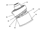
モーターシャフト24によって作動される典型的な回転ピストンポンプ22を図3に示す。モーターシャフト24は、モーターシャフトの周囲のスプライン(図示せず)と、ポンプバレル26の内面の、これに対応するスプライン(図示せず)とが結合することによってポンプバレル26を駆動する。これらのスプラインは、通常一対一で対応しているため、モーターシャフト24とポンプバレル26との間の相対回転が最小となっている。モーターシャフト24の後端部の内歯スプライン28により、モーターシャフト24とモーター自体の間の結合が得られる(図示せず)。ポンプ22は、ポンプバレル26で構成されており、ポンプバレル26は、これを通って延在する軸流シリンダ30を備える。各軸流シリンダ30の間の間隔は、ポンプバレル26の中心に対して等角である。ピストン32は、軸流シリンダ30内にあり、軸流シリンダ30内で自由に往復運動する。ピストン32は、カムプレート38によって導かれる回転プレート36に対し、シュー34によって連結される。カムプレート38は、ある角度に方向付けられており、それによって、常に、片側ではピストン32が軸流シリンダ30に完全に挿入され、反対側ではピストン32が軸流シリンダ30から引き出されるようになっている。
A typical
ポンプ22が通常に動作している間、モーターシャフト28は、モーターによって駆動され、ポンプバレル26を駆動してこれを回転させる。ポンプバレル26が回転すると、ピストン32が軸流シリンダ30内で往復運動して、流体がポンプバレル26に片側で吸入され、バレル26の反対側に吐出される。カムプレート38は固定角で図示されているが、ポンプから移送中である流体の量の制御を調節可能としてもよい。
During normal operation of the
図4は、ポンプ22の下側を見た図であり、詳しくは、ポンプバレル26の基部に取り付けられているポートプレート40を示している。ポートプレート40には、ポンプバレル26の軸流シリンダ30へのアクセスを提供する2つのポート42がある。2つのポート42は、半円形であり、ポンプバレル26内のシリンダ30の周方向の配置と同様の弧に沿って設けられている。2つのポート42を両者の間に間隔を置いて設けた目的は、ポンプの吐出側から流体が吸入されるのを妨ぐためである。2つのポート42の間の間隙は、カムプレート38上の勾配が正の勾配から負の勾配に、または負の勾配から正の勾配に変化する箇所に効果的に対応する。一方のポート42aはポンプ22への入口として機能するのに対し、他方のポート42bは出口として機能する。逆もまた同様である。
FIG. 4 is a view of the lower side of the
本開示に係る例示的な流体フロー図を図5及び6に示す。ポンプとは別のモードバルブを備えることによって減衰モードを実現するのではなく、ここでは、ポンプ106の中に内部的に組み込まれたバイパス流路123によって減衰モードが提供される。ポンプ106に動作可能に接続されているモーター104を図5に示す。ポンプ106の中には、バイパス流路123が組み込まれている。モーター104内の可動部材は、例えば、軸方向の可動部材であり、バイパス流体流路123を閉塞するように機能する。可動部材については、後の図面を参照して説明する。バイパス流路123は、ばね125によって開放される。通常動作中のポンプを図5に示す。能動モード中、モーター104が回転してポンプ106を作動させ、それによって流体が回路102に沿ってポンプ106を通じて運ばれる。モーター104は、バイパス流体流路123を物理的に閉塞するようにも機能する。太線及びこれに対応する矢印で示された流体経路を経由し、油圧アクチュエータ112のチャンバ114、116の間で流体を運ぶことができる。ラム18に接続された線形変換器144も図示されている。線形変換器14は、ラム18が使用中であるときを示すためのものである。別の線形変換器146もモーター104に接続されている。線形変換器146は、モーター内の構成要素によってバイパス流体流路123が閉塞されている/閉塞が解除されているときを示すためのものである。
Exemplary fluid flow diagrams according to the present disclosure are shown in FIGS. Rather than realizing a damped mode by providing a mode valve separate from the pump, here the damped mode is provided by a
減衰モードで作動しているポンプ106を図6に示す。減衰モードでは、モーター104は、もはや励磁されておらず、従ってポンプ106をもはや駆動していない。この減衰モードでは、ばね125が、バイパス流体流路を閉塞するモーター104の可動部材を移動させるように機能する。これにより、可動部材がバイパス流体流路123をもはや閉塞しないようにする。この減衰モードでは、油圧アクチュエータの各チャンバ114、116内の流体は、ポンプ106を通るバイパス流路123に沿って他のチャンバ114、116にまで自由に流れる。これは、典型的なピストンポンプでは不可能である。というのも、ポンプ106の一方の側のシリンダから他の側のシリンダに流体を移す手段がないためである。これは、本開示によって可能となり、以下の図面から理解することができる。
A
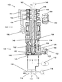
本開示の実施例に係る、モーター104、ポンプ106及び油圧アクチュエータ112を備えるEHA102を図7及び8に示す。EHA102は、図3に示したポンプ22と類似のポンプ106を備える。しかしながら、EHA102は、一部品のモーターシャフト124を利用する(すなわち、結合用スプライン28がない)。図7は、能動モード時のEHA102を示している。能動モードでは、ポンプ106は、モーターシャフト124によって回転するように駆動される。ポンプバレル126を駆動するために、モーターシャフト124は、モーター104からカムプレート138を通って通過する。モーターシャフト124は、通常、モーターシャフト124の周囲に設けられた一連のスプライン164(図9及び10に示す)、及びこれに対応する、ポンプバレル126の内部領域に設けられた一連のスプラインによってポンプバレル126を駆動する。モーターシャフト124は中空芯を備えており、これを通じて軸棒148が通される。軸棒148は、その下端に、ポンプ106に近接した下側ディスク形状部150を備える。ポンプバレル126内の軸流シリンダ130は、ポンプバレル126内の中央内部空洞に向かって通じる放射状の接続ポート152を備える。これらの接続ポート152は、これらが開いているときにバイパス流路を形成する。ばね125は、ポンプバレル126の中心部に設けられた凹部に配置される。ディスク形状部150は、ばね125と接触しており、中央空洞及び接続ポート152を閉塞するように機能する。軸棒148は、バイパス流路用のバルブとして効果的に機能する。これにより、能動モードでは、入口/出口を使って流体が軸流シリンダ130に入り、軸流シリンダ130から出ることのみが確実に可能となる。能動モードでは、流体が、ラム118を移動させる油圧アクチュエータ112の各チャンバ114、116へとポンプ106によって運ばれる。
An
図7は、モーター104の主要構成要素も示している。モーター104は、典型的なモーターと同様に作動し、3つの標準的な駆動コイル156及び永久磁石を利用して、モーターシャフト124を駆動する。通常、モーターは、ブラシレス交流モーターである。このモーターは、角度センサ及び制御電子回路を使用して電流を適切なコイルに切り替える。能動モードでは、電流がコイル156を流れ、永久磁石によって存在する磁場の中でコイル156に電流が存在するため、コイル/永久磁石に力が生じ、従って回転する。この回転によってモーターシャフト124が駆動され、回転する。軸棒148は、モーターシャフト124を通ってモーター104の主ハウジングにまで延在する。軸棒148は、モーター104内に収納された、さらなる3つの強磁性ディスク形状部154も備える。
FIG. 7 also shows the main components of the
3つの駆動コイル156と直列になっているのは、さらなる3つの「バルブ」コイル158である。3つのバルブコイル158は、モーター104のハウジングを囲んで環状に通っている。3つのバルブコイル158は、それぞれ隔てられており、軸棒148のディスク形状部154に近接してモーター104に配置されている。シャフト124の中には、3つの強磁性リング160がある。これらの環状強磁性リング160は、軸棒148を囲んで環状に通り、かつ所定位置に固定されており、各強磁性リング160は、軸棒148の対応する強磁性ディスク154に近接して配置されている。電流がバルブコイル158を流れると、電磁石が生成されて、軸棒148の強磁性ディスク形状部154に磁極を形成させる。3つの強磁性ディスク形状部154のそれぞれは、その後、それぞれに対応する強磁性リング160に引き寄せられる。これにより、各強磁性ディスク部154が対応する強磁性リング160に対して保持された状態の位置に棒148が保持される。強磁性リング160に対して保持されている強磁性ディスク154は、図7に示した拡大図から理解することができる。バルブコイル158は、モーターコイル156と直列に配線されており、モーターコイル156が励磁されたときにバルブコイル158が励磁されるようになっている。軸棒148は、モーター104が励磁されているとき、すなわちEHAが能動モードであるときには、この固定位置に保持される。
In series with the three
モーターによって作られた電磁石によって軸棒148が所定位置に保持されているとき、この位置は、接続ポート152を閉塞する位置に下側ディスク形状部150が押し込まれる「下側」位置である。この下側位置では、電磁石によって与えられた力が、ばね125によって与えられた弾性力に打ち勝つ必要がある。接続ポート152を閉塞している下側ディスク150は、ディスク部150の拡大図から理解することもできる。能動モードでは、ばね125の復元力が軸棒148を上方に押そうとする。しかしながら、軸棒148を所定位置に保持する、モーター内に作られた電磁石の強さにより、軸棒148は、軸方向に移動することができない。図7に示した実施例のEHAでは、能動モード時に、軸棒148がモーターシャフト124と共に回転する。しかしながら、いくつかの実施例では、軸棒148は、モーターシャフト124と共に回転しなくてもよく、むしろ、回転自在に固定されたままでもよいことが理解される。
When the
図7には、減衰調節ピン162も示されている。このピン162を用いて、油圧アクチュエータ112が受ける減衰量を制御することができる。ピン162により、軸棒148が移動してピン162と接触した時点で軸棒148がさらに移動しないようにする制限位置が提供される。これについては、図8に関してさらに詳しく説明する。
Also shown in FIG. 7 is an
減衰モード時のEHA102を図8に示す。このモードでは、モーターシャフト124はモーター104によって駆動されていない(すなわち、モーター104は励磁されていない)。この場合、駆動コイル156及びバルブコイル158は共に励磁されていないため、モーターシャフト124は回転せず、強磁性ディスク形状部154は電磁石に変わらない。このモードでは、ポンプ106内のバイパス流路が開いており、その結果、流体は、油圧アクチュエータ112のチャンバ114、116の間を通じて自由に流れることができる。この減衰モードでは、ばね125は、ディスク150を押し上げるように機能して、軸棒148を上方に移動させる。これにより、強磁性ディスク形状部154が強磁性リング160から離れるように移動する。これは、本図にも示した拡大図から理解することができる。下側ディスク150及び軸棒148がこのように上方へと移動することにより、バイパス流体流路が開放される。図上の矢印は、ポンプバレル126内の各軸流シリンダ130の間で流体が自由に流れることを示している。これにより、チャンバ114、116の間で流体を流すことができる。図示した実施例では、ばね125は、ある程度伸びてバイパス流路に達する。このことは減衰率に影響を与える場合があるため、他の実施例では、バイパス流路に影響を与えないようなばねの配置が可能となり得ることが理解される。
FIG. 8 shows the
図8は、軸棒148が移動して位置制限ピン162と接触する仕方も示している。ばね125が軸棒148を上方に押すように機能するとき、一番上の強磁性ディスク部154は、位置制限ピン162に対して当接する。この位置制限ピンは、軸棒148が軸方向にそれ以上移動しないようにするものであり、従って、バイパス流路を開放するためにどれだけ遠くまで下側ディスク150が移動することが可能であるかに対して影響を及ぼす。下側ディスク150のより広い部分でバイパス流路を部分的に遮断したままにさせることによって減衰率を調整することが可能であり、従って減衰率が大きくなることが理解される。図示した実施例では、位置制限ピン162を調節して、減衰率を調整することができる。ピン12は、ねじ付きであってもよく、あるいは当該位置に制御するためのその他の適切な手段を用いて提供されてもよい。調節可能な位置制限ピン162を用いることは特に有利である。というのも、減衰の度合いを製造後に調節することが可能となるためである。これは、様々なレベルの減衰を必要とする種々の用途の構成要素にEHAが使われる場合には特に有用となり得る。
FIG. 8 also shows how the
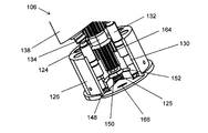
本開示に係るポンプ106の破断図を図9に示す。モーターシャフト124は、ポンプバレル126を駆動するように機能する複数の突起164を備える。この図は、能動モード時のポンプ106を示している。このモードでは、接続ポート152が閉塞されるように棒148の基部の下側ディスク部150が配置されていることが分かる。ばね125は、ポンプバレル126の中心部に配置されていることが分かる。能動モードでは、ばね125は、軸棒によって圧縮されるため、軸棒148を上方に付勢するように機能する。この能動モードでは、モーターシャフト124は、ポンプバレル126を駆動して回転させる。これにより、ピストン132がシリンダ130内で往復運動し、引き続いて流体が入口166から吸入され、出口166から吐出される。
A cutaway view of
本開示に係る減衰モード時のポンプ106の破断図を図10に示す。このモードでは、モーター104はもはや、励磁されておらず、駆動シャフト124及びモーター104の中で軸棒148を軸方向に移動させることができない。減衰モードでは、ばね125は、下側ディスク150を上方に押すことが可能であり、従ってバイパス流体流路を開放する。一旦下側ディスク150が移動して接続ポート152を開放すると、流体は、ポンプ106内に入り、シリンダ130への入口を通り、接続ポート152を通過し、異なるシリンダ130の出口から出ることが可能となる。これにより、ポンプ106を減衰モードで作動させることができる。
A cutaway view of the
いくつかの実施例では、特に、軸棒148がモーターシャフト124と共に回転することが可能である実施例では、下側ディスク150、モーターシャフト124及び接続ポート152の間のクリアランスを、バイパス流体流路によるリークの程度が能動モード時に減少するように設計する必要があることが理解される。あるいは、バイパス流路によるリークを防止するために組み込み可能な様々な別の特徴が有り得る。例えば、ゴムOリングを設けてバイパス流体流路を密封してもよい。
In some embodiments, particularly in embodiments where the
図示した実施例では、減衰モード時に、軸棒148は、ポンプバレル126内に配置されたばね125によってバイパス流体流路を強制的に開放する。1つのばね125が図示されているが、ばねを複数にしても同一の結果が得られることが理解される。軸棒126を移動させるための手段を必ずしもポンプバレル126内に配置しなくてもよいことも理解される。例えば、モーターシャフト124に沿った何処にでもばねを配置することが可能であり、当該ばねは、軸棒148を強制的に上方に移動させるために軸棒148のつまみに対して作用する。さらに、軸棒を移動させるためにばね125を図示しているが、その他の適切な手段(例えば、一連の磁石)を用いることができ、あるいは別の弾性材料を使用できることが理解される。
In the illustrated embodiment, during the damping mode, the
図示した実施例では、3つのバルブコイル158を用いて、軸棒148を固定位置に保持する。他の配置または異なる数のコイルを用いて同一の結果を実現できることが理解される。軸棒148を異なる位置に保持するために、コイルの位置取りを変えることができる。さらに、本実施例では、モーターコイル156と直列であるようにバルブコイル158を図示したが、この構成を必須としなくてもよく、例えば、コイルを並列に配置してもよいことが理解される。さらに、図示した本実施例ではバルブコイルがモーターコイル156に接続されているが、バルブコイルは、これら自体の電子制御を備えた別の回路の一部であってもよいことが理解される。
In the illustrated embodiment, three
上記で開示した実施例は、回転ピストンポンプに関する。ただし、その代わりに他の種類のポンプを用いてもよいことが理解されよう。さらに、図示した実施例ではカムプレートの角度が固定されているが、カムプレートの角度を変えることにより、ポンプによって吸入され、吐出される流体の量が変化するため、例えば、ポンプの用途に応じて流体の流量を修正するために、かかる角度を調節可能としてもよいことが理解される。 The embodiment disclosed above relates to a rotary piston pump. However, it will be appreciated that other types of pumps may be used instead. Furthermore, in the illustrated embodiment, the angle of the cam plate is fixed, but changing the angle of the cam plate changes the amount of fluid sucked and discharged by the pump. It will be appreciated that such angles may be adjustable in order to modify the fluid flow rate.
図示した実施例では、軸方向の可動部材148が、モーターシャフト124に設けられている。しかしながら、その他の適切な部材(例えば、バイパス流路を開放するために回転可能である部材)を設けてもよいことが理解される。例えば、ある角度方向で部材がバイパス流路を閉塞してもよく、別の角度方向で当該部材がバイパス流路を開いてもよい。
In the illustrated embodiment, an axially
Claims (15)
前記油圧ポンプは、作動流体の入口及び出口と、前記入口と前記出口の間に配置された能動的な流体流路と、を備え、前記油圧ポンプが前記電気モーターによって駆動されている能動動作モード時に、作動流体が能動的に前記入口から吸入されるとともに前記出口から吐出され、
前記油圧ポンプは、前記油圧ポンプの入口と出口の間に配置されたバイパス流路をさらに備え、減衰動作モード時に、作動流体が前記入口と前記出口の間を両方向に自由に流れることが可能となっており、
前記電気モーターは、該電気モーター内で移動するように配置された可動部材を備え、前記能動動作モード時において前記油圧ポンプを駆動するように前記電気モーターが励磁されているときに、前記可動部材が、前記バイパス流路を閉塞するように機能する閉塞位置となり、前記減衰動作モード時において前記電気モーターが励磁されていないときに、前記可動部材が前記電気モーター内で移動して前記バイパス流路を開放する、電気静油圧アクチュエータ。 A hydraulic pump, and an electric motor that drives the hydraulic pump to supply a working fluid to a hydraulic actuator,
The hydraulic pump includes an inlet and an outlet for a working fluid, and an active fluid flow path disposed between the inlet and the outlet, wherein the hydraulic pump is driven by the electric motor. Sometimes working fluid is actively drawn from the inlet and discharged from the outlet,
The hydraulic pump further includes a bypass channel disposed between an inlet and an outlet of the hydraulic pump, and the working fluid can freely flow in both directions between the inlet and the outlet in a damping operation mode. And
The electric motor includes a movable member arranged to move within the electric motor, and the movable member is energized when the electric motor is excited to drive the hydraulic pump in the active operation mode. Is a closed position that functions to close the bypass flow path, and the movable member moves within the electric motor when the electric motor is not excited in the damping operation mode, and the bypass flow path Open the electro-hydrostatic actuator.
能動動作モード時に、前記油圧アクチュエータに作動流体を供給するために電気モーターを励磁して油圧ポンプを駆動すること、及び
減衰動作モード時において前記油圧ポンプが前記電気モーターによって駆動されていないときに前記油圧ポンプを通るバイパス流路を開放するように、前記電気モーター内に配置された可動部材の移動を制御すること、
を含む方法。 A method for controlling and damping a hydraulic actuator,
Driving the hydraulic pump by exciting an electric motor to supply a working fluid to the hydraulic actuator during the active operation mode; and when the hydraulic pump is not driven by the electric motor during the damping operation mode. Controlling the movement of a movable member disposed in the electric motor to open a bypass flow path through the hydraulic pump;
Including methods.
Applications Claiming Priority (4)
| Application Number | Priority Date | Filing Date | Title |
|---|---|---|---|
| EP15306038.9A EP3112698B1 (en) | 2015-06-30 | 2015-06-30 | Electro hydrostatic actuators |
| EP15306038.9 | 2015-06-30 | ||
| EP15306480.3A EP3112699B1 (en) | 2015-06-30 | 2015-09-23 | Electro hydrostatic actuators |
| EP15306480.3 | 2015-09-23 |
Publications (2)
| Publication Number | Publication Date |
|---|---|
| JP2017015255A true JP2017015255A (en) | 2017-01-19 |
| JP6721424B2 JP6721424B2 (en) | 2020-07-15 |
Family
ID=53539623
Family Applications (2)
| Application Number | Title | Priority Date | Filing Date |
|---|---|---|---|
| JP2016117540A Active JP6659476B2 (en) | 2015-06-30 | 2016-06-14 | Electrohydrostatic actuator and method of controlling and damping hydraulic actuator |
| JP2016119441A Active JP6721424B2 (en) | 2015-06-30 | 2016-06-16 | Electro-hydrostatic actuator and control/damping method for hydraulic actuator |
Family Applications Before (1)
| Application Number | Title | Priority Date | Filing Date |
|---|---|---|---|
| JP2016117540A Active JP6659476B2 (en) | 2015-06-30 | 2016-06-14 | Electrohydrostatic actuator and method of controlling and damping hydraulic actuator |
Country Status (3)
| Country | Link |
|---|---|
| US (2) | US10611464B2 (en) |
| EP (2) | EP3112698B1 (en) |
| JP (2) | JP6659476B2 (en) |
Cited By (1)
| Publication number | Priority date | Publication date | Assignee | Title |
|---|---|---|---|---|
| JP2022510533A (en) * | 2018-08-02 | 2022-01-27 | ジーイーエー メカニカル イクイプメント イタリア エス.ピー.エー. | High pressure homogenizer |
Families Citing this family (14)
| Publication number | Priority date | Publication date | Assignee | Title |
|---|---|---|---|---|
| EP3112698B1 (en) | 2015-06-30 | 2019-09-04 | Goodrich Actuation Systems SAS | Electro hydrostatic actuators |
| CN107339282B (en) * | 2017-06-12 | 2019-06-04 | 南京航空航天大学 | A valveless electro-hydraulic actuator |
| EP3431758B1 (en) | 2017-07-17 | 2020-02-26 | Goodrich Actuation Systems SAS | Electro hydrostatic actuator |
| CN108019386B (en) * | 2017-12-08 | 2019-05-24 | 四川理工学院 | A kind of large size steel grasping machine efficient hydraulic swing arm energy conserving system |
| US10787247B2 (en) | 2018-01-16 | 2020-09-29 | Goodrich Corporation | Hybrid actuator |
| US11060539B2 (en) * | 2019-02-05 | 2021-07-13 | Regents Of The University Of Minnesota | Device having hybrid hydraulic-electric architecture |
| CN109899267A (en) * | 2019-03-08 | 2019-06-18 | 北京工业大学 | A kind of EHA driving plunger pump and its control method |
| US11624447B2 (en) * | 2019-05-13 | 2023-04-11 | Boston Dynamics, Inc. | Rotary valve assembly |
| DE102019121433B4 (en) * | 2019-08-08 | 2022-12-29 | SMC Deutschland GmbH | Fluid return device for a double-acting cylinder and method of operating such a cylinder |
| KR102216916B1 (en) * | 2019-08-27 | 2021-02-18 | 주식회사 케이브이엔텍 | Electro hydrostatic actuator for ship |
| DE102019131980A1 (en) * | 2019-11-26 | 2021-05-27 | Moog Gmbh | Electrohydrostatic system with pressure sensor |
| CN111219523A (en) * | 2020-01-07 | 2020-06-02 | 杭州孚罗泰自控阀门制造有限公司 | Miniature electro-hydraulic linkage actuator |
| IT202000025039A1 (en) * | 2020-10-22 | 2022-04-22 | I N A I L Istituto Naz Per L’Assicurazione Contro Gli Infortuni Sul Lavoro | PROSTHESIS FOR LIMBS OF THE HUMAN BODY AND ELECTRO-HYDROSTATIC ACTUATOR FOR THIS PROSTHESIS |
| CN114893456B (en) * | 2022-04-02 | 2023-02-17 | 北京航空航天大学 | One-way throttling load sensitive electro-hydrostatic actuator |
Family Cites Families (31)
| Publication number | Priority date | Publication date | Assignee | Title |
|---|---|---|---|---|
| US4934143A (en) | 1987-04-29 | 1990-06-19 | Vickers, Incorporated | Electrohydraulic fluid control system for variable displacement pump |
| US4859155A (en) * | 1987-10-21 | 1989-08-22 | Great Plains Industries, Inc. | Bypass valve for a displacement pump |
| US5144801A (en) | 1989-04-28 | 1992-09-08 | Parker Hannifin Corporation | Electro-hydraulic actuator system |
| FR2666787B1 (en) * | 1990-09-19 | 1992-12-18 | Aerospatiale | HYDRAULIC ACTUATOR WITH HYDROSTATIC MODE OF PREFERRED EMERGENCY OPERATION, AND FLIGHT CONTROL SYSTEM COMPRISING SAME. |
| US5338161A (en) * | 1991-06-19 | 1994-08-16 | Dana Corporation | Gear pump having internal bypass valve |
| US5097857A (en) * | 1991-08-02 | 1992-03-24 | John Mayhew | Electro-hydraulic valve-actuator system |
| US5515829A (en) * | 1994-05-20 | 1996-05-14 | Caterpillar Inc. | Variable-displacement actuating fluid pump for a HEUI fuel system |
| US5700136A (en) | 1996-07-23 | 1997-12-23 | Sturman Industries | Digital pump with bypass inlet valve |
| AU4251797A (en) * | 1996-09-12 | 1998-04-02 | Etrema Products, Inc. | Compact actuator and controller and pumping apparatus for same |
| US6575264B2 (en) * | 1999-01-29 | 2003-06-10 | Dana Corporation | Precision electro-hydraulic actuator positioning system |
| US6358018B1 (en) * | 1999-02-12 | 2002-03-19 | Parker Hannifin Ab | Hydraulic rotating axial piston engine |
| US6305919B1 (en) | 1999-08-24 | 2001-10-23 | Visteon Global Technologies, Inc. | Hydraulic pump housing with an integral dampener chamber |
| FR2811037B1 (en) | 2000-06-28 | 2002-10-18 | Aerospatiale Matra Airbus | ELECTRICALLY CONTROLLED HYDRAULIC ACTUATION SYSTEM |
| US7640736B2 (en) * | 2005-07-22 | 2010-01-05 | Ashradan Holdings Ltd. | Self-contained hydraulic actuator system |
| US7191593B1 (en) | 2005-11-28 | 2007-03-20 | Northrop Grumman Corporation | Electro-hydraulic actuator system |
| US20070157612A1 (en) * | 2006-01-10 | 2007-07-12 | Xinhua He | Compact hydraulic actuator system |
| EP1878598A1 (en) | 2006-07-13 | 2008-01-16 | Fondazione Torino Wireless | Regenerative suspension for a vehicle |
| US7434395B2 (en) * | 2006-07-25 | 2008-10-14 | Delphi Technologies, Inc. | Apparatus and method for dual mode compact hydraulic system |
| JP5214575B2 (en) * | 2009-10-20 | 2013-06-19 | カヤバ工業株式会社 | Electric hydraulic actuator |
| JP5606044B2 (en) | 2009-11-10 | 2014-10-15 | 住友精密工業株式会社 | ELECTRO-HYDRAULIC ACTUATOR EXCELLENT IN SNAVING, DRIVE DEVICE USED FOR THE SAME, AND CONTROL METHOD USED FOR THE SAME |
| US8434301B2 (en) | 2010-04-16 | 2013-05-07 | Nabtesco Corporation | Local backup hydraulic actuator for aircraft control systems |
| US8935015B2 (en) | 2011-05-09 | 2015-01-13 | Parker-Hannifin Corporation | Flight control system with alternate control path |
| JP5890987B2 (en) | 2011-09-15 | 2016-03-22 | 住友精密工業株式会社 | Electric hydraulic actuator |
| US8973864B2 (en) * | 2012-08-02 | 2015-03-10 | Bell Helicopter Textron Inc. | Independent blade control system with hydraulic cyclic control |
| WO2014074713A1 (en) | 2012-11-07 | 2014-05-15 | Parker-Hannifin Corporation | Smooth control of hydraulic actuator |
| JP6396414B2 (en) | 2013-03-15 | 2018-09-26 | クリアモーション,インコーポレイテッド | Multi-path fluid diverter valve |
| KR102154663B1 (en) | 2013-04-22 | 2020-09-11 | 파커-한니핀 코포레이션 | Method of increasing electro-hydrostatic actuator piston velocity |
| CN103722996A (en) | 2014-01-10 | 2014-04-16 | 湖南大学 | Hydraulic buffer energy recovering system based on electric energy storage element and hydraulic buffer energy recovering control method based on electric energy storage element |
| CN104196080B (en) | 2014-09-17 | 2016-02-03 | 太原理工大学 | Variable speed volume directly drives pure electric hydraulic crawler excavator and drives and energy-recuperation system |
| EP3112698B1 (en) * | 2015-06-30 | 2019-09-04 | Goodrich Actuation Systems SAS | Electro hydrostatic actuators |
| EP3257746B1 (en) | 2016-06-13 | 2020-05-13 | Goodrich Actuation Systems SAS | Electro hydrostatic actuators |
-
2015
- 2015-06-30 EP EP15306038.9A patent/EP3112698B1/en active Active
- 2015-09-23 EP EP15306480.3A patent/EP3112699B1/en active Active
-
2016
- 2016-06-14 JP JP2016117540A patent/JP6659476B2/en active Active
- 2016-06-16 JP JP2016119441A patent/JP6721424B2/en active Active
- 2016-06-30 US US15/198,001 patent/US10611464B2/en active Active
- 2016-06-30 US US15/197,975 patent/US10087962B2/en active Active
Cited By (2)
| Publication number | Priority date | Publication date | Assignee | Title |
|---|---|---|---|---|
| JP2022510533A (en) * | 2018-08-02 | 2022-01-27 | ジーイーエー メカニカル イクイプメント イタリア エス.ピー.エー. | High pressure homogenizer |
| JP7329546B2 (en) | 2018-08-02 | 2023-08-18 | ジーイーエー メカニカル イクイプメント イタリア エス.ピー.エー. | high pressure homogenizer |
Also Published As
| Publication number | Publication date |
|---|---|
| JP6659476B2 (en) | 2020-03-04 |
| US20170002845A1 (en) | 2017-01-05 |
| EP3112699A1 (en) | 2017-01-04 |
| JP6721424B2 (en) | 2020-07-15 |
| EP3112698A1 (en) | 2017-01-04 |
| JP2017015253A (en) | 2017-01-19 |
| EP3112698B1 (en) | 2019-09-04 |
| US10087962B2 (en) | 2018-10-02 |
| EP3112699B1 (en) | 2020-12-30 |
| US10611464B2 (en) | 2020-04-07 |
| US20170002844A1 (en) | 2017-01-05 |
Similar Documents
| Publication | Publication Date | Title |
|---|---|---|
| JP6721424B2 (en) | Electro-hydrostatic actuator and control/damping method for hydraulic actuator | |
| US9482365B2 (en) | Rotary valve | |
| US8678033B2 (en) | Proportional valve employing simultaneous and hybrid actuation | |
| JP5890987B2 (en) | Electric hydraulic actuator | |
| US10450061B2 (en) | Servo actuators | |
| JP2016506479A (en) | Electrohydraulic pressure reduction and release valve with fluid force control for large flow capacity | |
| EP3129660B1 (en) | Servo valve | |
| JP6075866B2 (en) | Pump control device | |
| JP6248144B2 (en) | Pump device | |
| US10539131B2 (en) | Electro hydrostatic actuator | |
| JP5645236B2 (en) | Electric oil hybrid drive unit | |
| US9915368B2 (en) | Electrohydraulic valve having dual-action right-angle pilot actuator | |
| JP2013185668A (en) | Actuator | |
| CN103821787A (en) | Hydraulic pilot-operated independent load multi-way valve adopting pressure-torsion two-dimensional spring | |
| JPH0642149Y2 (en) | Electromagnetic drive control valve | |
| JP2020143686A (en) | Actuator system | |
| US20230175534A1 (en) | Servo valve | |
| JP2018151032A (en) | Fluid pressure cylinder and fluid pressure drive unit | |
| JPH07310687A (en) | Vane type hydraulic machine | |
| JP2017065471A (en) | Suspension device | |
| JPH0571560A (en) | Hydraulic type power transmission coupling |
Legal Events
| Date | Code | Title | Description |
|---|---|---|---|
| A621 | Written request for application examination |
Free format text: JAPANESE INTERMEDIATE CODE: A621 Effective date: 20181218 |
|
| A977 | Report on retrieval |
Free format text: JAPANESE INTERMEDIATE CODE: A971007 Effective date: 20190924 |
|
| A131 | Notification of reasons for refusal |
Free format text: JAPANESE INTERMEDIATE CODE: A131 Effective date: 20191029 |
|
| A601 | Written request for extension of time |
Free format text: JAPANESE INTERMEDIATE CODE: A601 Effective date: 20200128 |
|
| A521 | Request for written amendment filed |
Free format text: JAPANESE INTERMEDIATE CODE: A523 Effective date: 20200318 |
|
| TRDD | Decision of grant or rejection written | ||
| A01 | Written decision to grant a patent or to grant a registration (utility model) |
Free format text: JAPANESE INTERMEDIATE CODE: A01 Effective date: 20200519 |
|
| A61 | First payment of annual fees (during grant procedure) |
Free format text: JAPANESE INTERMEDIATE CODE: A61 Effective date: 20200618 |
|
| R150 | Certificate of patent or registration of utility model |
Ref document number: 6721424 Country of ref document: JP Free format text: JAPANESE INTERMEDIATE CODE: R150 |
|
| R250 | Receipt of annual fees |
Free format text: JAPANESE INTERMEDIATE CODE: R250 |
|
| R250 | Receipt of annual fees |
Free format text: JAPANESE INTERMEDIATE CODE: R250 |
|
| R250 | Receipt of annual fees |
Free format text: JAPANESE INTERMEDIATE CODE: R250 |