JP2017014635A - Sock knitting machine - Google Patents
Sock knitting machine Download PDFInfo
- Publication number
- JP2017014635A JP2017014635A JP2015129662A JP2015129662A JP2017014635A JP 2017014635 A JP2017014635 A JP 2017014635A JP 2015129662 A JP2015129662 A JP 2015129662A JP 2015129662 A JP2015129662 A JP 2015129662A JP 2017014635 A JP2017014635 A JP 2017014635A
- Authority
- JP
- Japan
- Prior art keywords
- yarn
- brush
- knitting machine
- air suction
- sock knitting
- Prior art date
- Legal status (The legal status is an assumption and is not a legal conclusion. Google has not performed a legal analysis and makes no representation as to the accuracy of the status listed.)
- Granted
Links
- 238000009940 knitting Methods 0.000 title claims abstract description 72
- 238000005520 cutting process Methods 0.000 claims abstract description 30
- 238000000926 separation method Methods 0.000 claims description 5
- 230000002265 prevention Effects 0.000 abstract 1
- 239000004743 Polypropylene Substances 0.000 description 6
- 210000004177 elastic tissue Anatomy 0.000 description 6
- -1 polypropylene Polymers 0.000 description 6
- 229920001155 polypropylene Polymers 0.000 description 6
- 230000009471 action Effects 0.000 description 4
- 230000008859 change Effects 0.000 description 4
- 238000000034 method Methods 0.000 description 4
- 229920000728 polyester Polymers 0.000 description 4
- 230000008901 benefit Effects 0.000 description 2
- 230000000052 comparative effect Effects 0.000 description 2
- 238000001514 detection method Methods 0.000 description 2
- 230000007261 regionalization Effects 0.000 description 2
- 230000004044 response Effects 0.000 description 2
Images

Landscapes
- Knitting Machines (AREA)
Abstract
Description
本発明は、靴下編機に関する。 The present invention relates to a sock knitting machine.
従来から靴下編機に於ては、靴下を編成する途中で、(複数本の)糸の本数の増減や、糸の種類の変更や、模様形成のための色彩糸の変更等のために、瞬間的に糸の送りを停止し、複数本の糸を切り替えて、元の糸を切断し、次の糸に切り替えている。糸を切断する際には、糸の端部をエア吸込管にて上方へ吸引し、切断した旧の糸の引き抜けを防止している(特許文献1参照)。 Conventionally, in sock knitting machines, during the knitting of socks, in order to increase or decrease the number of (multiple) yarns, change the type of yarn, change the color yarn for pattern formation, The yarn feed is instantaneously stopped, a plurality of yarns are switched, the original yarn is cut, and the next yarn is switched. When cutting the yarn, the end of the yarn is sucked upward by an air suction pipe to prevent the old yarn from being pulled out (see Patent Document 1).
特許文献1記載の靴下編機は、図8に示すように、例えば、ポリエステルやポリプロピレンの弾性繊維を素材とする糸40を切断する際に、エア吸込管39で糸40の端部41を吸引しつつ、ブラシ42で糸40の端部41を(受け面に対して)押圧保持すべく瞬時に下降させ、このブラシ42と受け面にて、切断した(旧の)糸40の端部41を挟圧して保持する構成であった。
ところが、上記切断以前の走行中の糸40の内の一部の糸40Aが、矢印Gの方向に外側に位置ずれしてブラシ42の外側部42Bに存在する場合があって、ブラシ42が下降しても、一部の糸40Aを挟圧保持できず、弾発力で縮んで逃げて引き抜けを発生する欠点があった。
As shown in FIG. 8, the sock knitting machine described in
However, there is a case where a part of the running
そこで、本発明は、切断した糸を確実に保持して引き抜けを防止する靴下編機を提供することを目的とする。 Then, an object of this invention is to provide the sock knitting machine which hold | maintains the cut | disconnected thread | yarn reliably and prevents pulling out.
本発明に係る靴下編機は、複数本の糸を用いて靴下を編成する靴下編機に於て、切断工程にて切断した糸の端部を吸引するエア吸込管を備え、上記エア吸込管の近傍位置で糸の端部を受け面に対して上方から押さえるブラシと、糸を装置中心部側へ案内して上記ブラシと上記受け面との接触部位から糸がブラシ外側部側へ離脱するのを防ぐ離脱防止用のローラとを、備えたものである。 A sock knitting machine according to the present invention comprises an air suction pipe for sucking an end portion of a thread cut in a cutting process in the sock knitting machine for knitting socks using a plurality of yarns, and the air suction pipe A brush that presses the end of the yarn against the receiving surface from above at a position near the center, and guides the yarn toward the center of the apparatus, and the yarn is detached from the contact portion between the brush and the receiving surface toward the outer side of the brush. And a roller for preventing separation.
また、複数本の糸を用いて靴下を編成する靴下編機に於て、切断工程にて切断した糸の端部を吸引するエア吸込管を備え、上記エア吸込管の近傍位置で糸の端部を受け面に対して上方から押さえつつ糸を上記エア吸込管側に引っ張って張力を付与する糸保持手段を備えたものである。 In the sock knitting machine for knitting socks using a plurality of yarns, the sock knitting machine is provided with an air suction pipe for sucking the end of the yarn cut in the cutting process, and the end of the yarn is positioned near the air suction pipe. A thread holding means for applying tension by pulling the thread toward the air suction pipe side while pressing the portion from the upper side against the receiving surface is provided.
本発明の靴下編機によれば、ローラによって糸を装置中心部側に案内することで、糸の端部がブラシ外側部側に逃げてブラシから離脱するのを防止でき、ブラシで糸を確実に押さえて保持することができる。構造が簡素で、既存の装置にローラを容易に組込むことができ、低コストで簡単に糸の離脱を防止できる。 According to the sock knitting machine of the present invention, it is possible to prevent the end of the yarn from escaping to the outer side of the brush and detaching from the brush by guiding the yarn to the center of the apparatus by the roller, and the yarn can be surely secured by the brush. Can be held down. The structure is simple, the roller can be easily incorporated into an existing apparatus, and the yarn can be easily prevented from being detached at a low cost.
また、切断された糸に張力を付与して、糸の端部が装置外方に逃げるのを防止でき、糸を上方から押さえて確実に保持することができる。構造が簡素で、既存の装置に糸保持手段を容易に組込むことができ、低コストで簡単に糸の離脱を防止できる。 Further, tension can be applied to the cut yarn to prevent the end portion of the yarn from escaping to the outside of the apparatus, and the yarn can be held securely by pressing from above. The structure is simple, the thread holding means can be easily incorporated into an existing apparatus, and the thread can be easily prevented from being detached at low cost.
以下、実施の形態を示す図面に基づき本発明を詳説する。
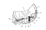
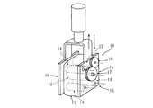
図1と図2に示すように、本発明の靴下編機は、複数本の糸Yを切り替えて使用し、糸Yを切り替える際にサーキュラカッタ7と固定刃8によって糸Yを切断する鋏台3を有している。鋏台3は、図示省略の編機シリンダの上部に設けられている。鋏台3の外側には、糸道切換装置20を有する給糸ユニットが配設されている。なお、編機シリンダと鋏台3は、公知の従来品と同様の構成である為、詳しい説明を省略する。
鋏台3上には、切断した糸Yの端部を吸引するエア吸込管9が立設され、糸Yの端部を鋏台3の上面(受け面4)に対して上方から押さえるブラシ2と、糸Yを装置中心部C側へ案内してブラシ2と受け面4との接触部位Zから糸Yがブラシ外側部2B側へ離脱するのを防ぐ離脱防止用のローラ6とを、備えている。
Hereinafter, the present invention will be described in detail with reference to the drawings illustrating embodiments.
As shown in FIGS. 1 and 2, the sock knitting machine of the present invention switches a plurality of yarns Y and uses the circular cutter 7 and the
An
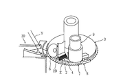
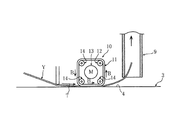
図3に示すように、ブラシ2は、エア吸込管9の近傍位置に配設され、昇降自在の保持枠体21に取着されている。即ち、ブラシ2は、保持枠体21と共に上下方向に昇降し、糸Yを切断する時に必要に応じて、糸Yを鋏台3の上面(受け面4)との間で挟圧保持するよう構成されている。
ローラ6は、ブラシ2と給糸ユニットの間に配設され、昇降自在の枢支枠体22に回転軸心L0廻りに回転自在に枢着されている。ローラ6は、ブラシ2の昇降に対応して上下動し、鋏台3の上面(受け面4)に摺接しつつ、糸Yを装置中心部C側へ案内するように構成されている。図4に示すように、ローラ6は、側端面に複数の羽根片23を有し、この羽根片23に上方からエアーを吹き付けて、矢印Rの方向に回転駆動される。
なお、ローラ6は、電気モーターによって電気的に回転駆動しても良い。そして、複数本の糸Yを糸道切換装置20にて切り替える際に、元の糸Yを上昇させ、次の糸Yを降下させるが、元の糸Yを上昇させる動きを(図示省略の)センサーにて検出して、直ちに上記電気モーターを回動させて、糸Yを装置中心部C側へ案内開始するのが望ましい。
As shown in FIG. 3, the
The
上述した本発明の靴下編機の使用方法(作用)について説明する。
図3に示すように、本発明の靴下編機は、靴下の編成途中で、ポリエステルやポリプロピレンの弾性繊維を素材とする糸(柄糸)Yを切断する場合に、切断の事前に、糸Yをブラシ2で鋏台3の上面(受け面4)に対して上方から押圧(挟圧)する。糸Yの端部は、切断と同時に、エア吸込管9によって上方へ吸引される。この際、又は、上記押圧(挟圧)の直前に、ローラ6は、矢印Rの方向に回転して、鋏台3の上面(受け面4)に摺接しつつ糸Yを装置中心部C側へ案内して、ブラシ2と受け面4との接触部位Zから糸Yがブラシ外側部2B側へ離脱するのを防止する。このようにして、鋏台3のサーキュラカッタ7と固定刃8によって糸Yを切断し、糸Yの端部は、ブラシ2とローラ6によって、ブラシ2と受け面4との接触部位Zに張力を維持しつつ保持される。
The use method (action) of the above-described sock knitting machine of the present invention will be described.
As shown in FIG. 3, when the sock knitting machine of the present invention cuts a yarn (pattern yarn) Y made of an elastic fiber of polyester or polypropylene during the sock knitting, the yarn Y is cut before cutting. Is pressed (clamped) from above with the
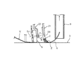
次に、本発明の他の実施形態を説明する。
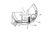
図5に示すように、複数本の糸Yを用いて靴下を編成する靴下編機に於て、切断工程にて切断した糸Yの端部を吸引するエア吸込管9を備え、エア吸込管9の近傍位置で糸Yの端部を鋏台3の上面(受け面4)に対して上方から押さえつつ糸Yをエア吸込管9側に引っ張って張力を付与する糸保持手段10を備えている。
Next, another embodiment of the present invention will be described.
As shown in FIG. 5, in a sock knitting machine for knitting socks using a plurality of yarns Y, an
図6に於て、糸保持手段10は、一対の板片部16,16を有する下方開放状のケース部15を備え、このケース部15に、電気モーター13が内装され、さらに、電気モーター13により回転駆動される駆動ローラー12と、複数個のプーリー(滑車)14とが、回転自在に枢着されている。駆動ローラー12と3個のプーリー14,14,14によって、弾性ゴム製の無端状ベルト部材11が張設されており、ベルト部材11の下端縁部は、ケース部15の下端縁から(下方へ)突出している。即ち、ベルト部材11は、軸心方向から見ると、略四角形状となるように張設されており、この構成により、糸Yとの接触面積が拡大する利点がある。なお、ベルト部材11は、駆動ローラー12と2個のプーリー14,14によって、略三角形状となるように張設されていても良い(図示省略)。
電気モーター13と駆動ローラー12は、互いに噛合する駆動ギア17,18を介して連動連結されており、電気モーター13によって駆動ローラー12を回転駆動することで、ベルト部材11が循環(回転)する。糸保持手段10は、昇降自在であって、糸Yを切断する直前に、糸Yを鋏台3の上面(受け面4)との間で挟圧するよう構成されている。ところで、糸保持手段10を下降させるために、図示省略のセンサーを付設して、このセンサーによって、糸道切換装置20による元の糸Yの上昇を検出し、その検出信号によって、下降させるのが望ましい。さらに、この下降開始と同時に電気モーター13を回動させるのが良い。
In FIG. 6, the thread holding means 10 includes a lower
The
上述した本発明の靴下編機の使用方法(作用)について説明する。
図7に示すように、本発明の靴下編機は、靴下の編成途中で、ポリプロピレン等の弾性繊維を素材とする糸(柄糸)Yを切断する場合に、切断の事前に、糸Yを糸保持手段10で鋏台3の上面(受け面4)に対して上方から押圧(挟圧)する。糸Yの端部は、切断と同時に、エア吸込管9によって上方へ吸引される。上記押圧(挟圧)の直前に、糸保持手段10は、電気モーター13によりベルト部材11を矢印Bのように回転させ、糸Yの端部を鋏台3の上面(受け面4)に対して上方から押さえつつ糸Yをエア吸込管9側に引っ張って張力Tを付与して、糸Yが離脱するのを防止する。このようにして、鋏台3のサーキュラカッタ7と固定刃8によって糸Yを切断し、糸Yの端部は、糸保持手段10によって、張力Tを維持しつつ保持される。
The use method (action) of the above-described sock knitting machine of the present invention will be described.
As shown in FIG. 7, when the sock knitting machine of the present invention cuts a yarn (pattern yarn) Y made of elastic fibers such as polypropylene during the sock knitting, the yarn Y is cut before cutting. The yarn holding means 10 presses (clamps) the upper surface (receiving surface 4) of the
なお、本発明は、設計変更可能であって、例えば、糸保持手段10は、糸Yの端部を鋏台3の上面(受け面4)に対して上方から押さえつつ糸Yをエア吸込管9側に引っ張るローラをもって構成しても良い(図示省略)。
In the present invention, the design can be changed. For example, the yarn holding means 10 presses the end of the yarn Y against the upper surface (receiving surface 4) of the
以上のように、本発明に係る靴下編機は、複数本の糸Yを用いて靴下を編成する靴下編機に於て、切断工程にて切断した糸Yの端部を吸引するエア吸込管9を備え、エア吸込管9の近傍位置で糸Yの端部を受け面4に対して上方から押さえるブラシ2と、糸Yを装置中心部C側へ案内してブラシ2と受け面4との接触部位Zから糸Yがブラシ外側部2B側へ離脱するのを防ぐ離脱防止用のローラ6とを、備えたので、ローラ6によって糸Yを装置中心部C側に案内することで、糸Yの端部がブラシ外側部2B側に逃げてブラシ2から離脱するのを防止でき、ブラシ2で糸Yを確実に押さえて保持することができる。構造が簡素で、既存の装置にローラ6を容易に組込むことができ、低コストで簡単に糸Yの離脱を防止できる。
As described above, the sock knitting machine according to the present invention is a sock knitting machine that knits socks using a plurality of yarns Y, and an air suction pipe that sucks the end of the yarn Y cut in the cutting process. 9, a
また、複数本の糸Yを用いて靴下を編成する靴下編機に於て、切断工程にて切断した糸Yの端部を吸引するエア吸込管9を備え、エア吸込管9の近傍位置で糸Yの端部を受け面4に対して上方から押さえつつ糸Yをエア吸込管9側に引っ張って張力Tを付与する糸保持手段10を備えたので、切断された糸Yに張力Tを付与して、糸Yの端部が装置外方に逃げるのを防止でき、糸Yを上方から押さえて確実に保持することができる。構造が簡素で、既存の装置に糸保持手段10を容易に組込むことができ、低コストで簡単に糸Yの離脱を防止できる。
Further, in the sock knitting machine for knitting socks using a plurality of yarns Y, the sock knitting machine is provided with an
2 ブラシ
2B ブラシ外側部
4 受け面
6 ローラ
9 エア吸込管
10 糸保持手段
Y 糸
C 装置中心部
T 張力
Z 接触部位
2
本発明は、靴下編機に関する。 The present invention relates to a sock knitting machine.
従来から靴下編機に於ては、靴下を編成する途中で、(複数本の)糸の本数の増減や、糸の種類の変更や、模様形成のための色彩糸の変更等のために、瞬間的に糸の送りを停止し、複数本の糸を切り替えて、元の糸を切断し、次の糸に切り替えている。糸を切断する際には、糸の端部をエア吸込管にて上方へ吸引し、切断した旧の糸の引き抜けを防止している(特許文献1参照)。 Conventionally, in sock knitting machines, during the knitting of socks, in order to increase or decrease the number of (multiple) yarns, change the type of yarn, change the color yarn for pattern formation, The yarn feed is instantaneously stopped, a plurality of yarns are switched, the original yarn is cut, and the next yarn is switched. When cutting the yarn, the end of the yarn is sucked upward by an air suction pipe to prevent the old yarn from being pulled out (see Patent Document 1).
特許文献1記載の靴下編機は、図8に示すように、例えば、ポリエステルやポリプロピレンの弾性繊維を素材とする糸40を切断する際に、エア吸込管39で糸40の端部41を吸引しつつ、ブラシ42で糸40の端部41を(受け面に対して)押圧保持すべく瞬時に下降させ、このブラシ42と受け面にて、切断した(旧の)糸40の端部41を挟圧して保持する構成であった。
ところが、上記切断以前の走行中の糸40の内の一部の糸40Aが、矢印Gの方向に外側に位置ずれしてブラシ42の外側部42Bに存在する場合があって、ブラシ42が下降しても、一部の糸40Aを挟圧保持できず、弾発力で縮んで逃げて引き抜けを発生する欠点があった。
As shown in FIG. 8, the sock knitting machine described in
However, there is a case where a part of the running
そこで、本発明は、切断した糸を確実に保持して引き抜けを防止する靴下編機を提供することを目的とする。 Then, an object of this invention is to provide the sock knitting machine which hold | maintains the cut | disconnected thread | yarn reliably and prevents pulling out.
本発明に係る靴下編機は、複数本の糸を用いて靴下を編成する靴下編機に於て、切断工程にて切断した糸の端部を吸引するエア吸込管を備え、上記エア吸込管の近傍位置で糸の端部を受け面に対して上方から押さえるブラシと、糸を装置中心部側へ案内して上記ブラシと上記受け面との接触部位から糸がブラシ外側部側へ離脱するのを防ぐ離脱防止用のローラとを、備えたものである。 A sock knitting machine according to the present invention comprises an air suction pipe for sucking an end portion of a thread cut in a cutting process in the sock knitting machine for knitting socks using a plurality of yarns, and the air suction pipe A brush that presses the end of the yarn against the receiving surface from above at a position near the center, and guides the yarn toward the center of the apparatus, and the yarn is detached from the contact portion between the brush and the receiving surface toward the outer side of the brush. And a roller for preventing separation .
本発明の靴下編機によれば、ローラによって糸を装置中心部側に案内することで、糸の端部がブラシ外側部側に逃げてブラシから離脱するのを防止でき、ブラシで糸を確実に押さえて保持することができる。構造が簡素で、既存の装置にローラを容易に組込むことができ、低コストで簡単に糸の離脱を防止できる。 According to the sock knitting machine of the present invention, it is possible to prevent the end of the yarn from escaping to the outer side of the brush and detaching from the brush by guiding the yarn to the center of the apparatus by the roller, and the yarn can be surely secured by the brush. Can be held down. The structure is simple, the roller can be easily incorporated into an existing apparatus, and the yarn can be easily prevented from being detached at a low cost .
以下、実施の形態を示す図面に基づき本発明を詳説する。
図1と図2に示すように、本発明の靴下編機は、複数本の糸Yを切り替えて使用し、糸Yを切り替える際にサーキュラカッタ7と固定刃8によって糸Yを切断する鋏台3を有している。鋏台3は、図示省略の編機シリンダの上部に設けられている。鋏台3の外側には、糸道切換装置20を有する給糸ユニットが配設されている。なお、編機シリンダと鋏台3は、公知の従来品と同様の構成である為、詳しい説明を省略する。
鋏台3上には、切断した糸Yの端部を吸引するエア吸込管9が立設され、糸Yの端部を鋏台3の上面(受け面4)に対して上方から押さえるブラシ2と、糸Yを装置中心部C側へ案内してブラシ2と受け面4との接触部位Zから糸Yがブラシ外側部2B側へ離脱するのを防ぐ離脱防止用のローラ6とを、備えている。
Hereinafter, the present invention will be described in detail with reference to the drawings illustrating embodiments.
As shown in FIGS. 1 and 2, the sock knitting machine of the present invention switches a plurality of yarns Y and uses the circular cutter 7 and the fixed
An
図3に示すように、ブラシ2は、エア吸込管9の近傍位置に配設され、昇降自在の保持枠体21に取着されている。即ち、ブラシ2は、保持枠体21と共に上下方向に昇降し、糸Yを切断する時に必要に応じて、糸Yを鋏台3の上面(受け面4)との間で挟圧保持するよう構成されている。
ローラ6は、ブラシ2と給糸ユニットの間に配設され、昇降自在の枢支枠体22に回転軸心L0廻りに回転自在に枢着されている。ローラ6は、ブラシ2の昇降に対応して上下動し、鋏台3の上面(受け面4)に摺接しつつ、糸Yを装置中心部C側へ案内するように構成されている。図4に示すように、ローラ6は、側端面に複数の羽根片23を有し、この羽根片23に上方からエアーを吹き付けて、矢印Rの方向に回転駆動される。
なお、ローラ6は、電気モーターによって電気的に回転駆動しても良い。そして、複数本の糸Yを糸道切換装置20にて切り替える際に、元の糸Yを上昇させ、次の糸Yを降下させるが、元の糸Yを上昇させる動きを(図示省略の)センサーにて検出して、直ちに上記電気モーターを回動させて、糸Yを装置中心部C側へ案内開始するのが望ましい。
As shown in FIG. 3, the
The
上述した本発明の靴下編機の使用方法(作用)について説明する。
図3に示すように、本発明の靴下編機は、靴下の編成途中で、ポリエステルやポリプロピレンの弾性繊維を素材とする糸(柄糸)Yを切断する場合に、切断の事前に、糸Yをブラシ2で鋏台3の上面(受け面4)に対して上方から押圧(挟圧)する。糸Yの端部は、切断と同時に、エア吸込管9によって上方へ吸引される。この際、又は、上記押圧(挟圧)の直前に、ローラ6は、矢印Rの方向に回転して、鋏台3の上面(受け面4)に摺接しつつ糸Yを装置中心部C側へ案内して、ブラシ2と受け面4との接触部位Zから糸Yがブラシ外側部2B側へ離脱するのを防止する。このようにして、鋏台3のサーキュラカッタ7と固定刃8によって糸Yを切断し、糸Yの端部は、ブラシ2とローラ6によって、ブラシ2と受け面4との接触部位Zに張力を維持しつつ保持される。
The use method (action) of the above-described sock knitting machine of the present invention will be described.
As shown in FIG. 3, when the sock knitting machine of the present invention cuts a yarn (pattern yarn) Y made of an elastic fiber of polyester or polypropylene during the sock knitting, the yarn Y is cut before cutting. Is pressed (clamped) from above with the
次に、本発明と関連のある比較例について説明する。
図5に示すように、複数本の糸Yを用いて靴下を編成する靴下編機に於て、切断工程にて切断した糸Yの端部を吸引するエア吸込管9を備え、エア吸込管9の近傍位置で糸Yの端部を鋏台3の上面(受け面4)に対して上方から押さえつつ糸Yをエア吸込管9側に引っ張って張力を付与する糸保持手段10を備えている。
Next, a comparative example related to the present invention will be described.
As shown in FIG. 5, in a sock knitting machine for knitting socks using a plurality of yarns Y, an
図6に於て、糸保持手段10は、一対の板片部16,16を有する下方開放状のケース部15を備え、このケース部15に、電気モーター13が内装され、さらに、電気モーター13により回転駆動される駆動ローラー12と、複数個のプーリー(滑車)14とが、回転自在に枢着されている。駆動ローラー12と3個のプーリー14,14,14によって、弾性ゴム製の無端状ベルト部材11が張設されており、ベルト部材11の下端縁部は、ケース部15の下端縁から(下方へ)突出している。即ち、ベルト部材11は、軸心方向から見ると、略四角形状となるように張設されており、この構成により、糸Yとの接触面積が拡大する利点がある。なお、ベルト部材11は、駆動ローラー12と2個のプーリー14,14によって、略三角形状となるように張設されていても良い(図示省略)。
電気モーター13と駆動ローラー12は、互いに噛合する駆動ギア17,18を介して連動連結されており、電気モーター13によって駆動ローラー12を回転駆動することで、ベルト部材11が循環(回転)する。糸保持手段10は、昇降自在であって、糸Yを切断する直前に、糸Yを鋏台3の上面(受け面4)との間で挟圧するよう構成されている。ところで、糸保持手段10を下降させるために、図示省略のセンサーを付設して、このセンサーによって、糸道切換装置20による元の糸Yの上昇を検出し、その検出信号によって、下降させるのが望ましい。さらに、この下降開始と同時に電気モーター13を回動させるのが良い。
In FIG. 6, the thread holding means 10 includes a lower
The
上述した本発明の靴下編機の使用方法(作用)について説明する。
図7に示すように、本発明の靴下編機は、靴下の編成途中で、ポリプロピレン等の弾性繊維を素材とする糸(柄糸)Yを切断する場合に、切断の事前に、糸Yを糸保持手段10で鋏台3の上面(受け面4)に対して上方から押圧(挟圧)する。糸Yの端部は、切断と同時に、エア吸込管9によって上方へ吸引される。上記押圧(挟圧)の直前に、糸保持手段10は、電気モーター13によりベルト部材11を矢印Bのように回転させ、糸Yの端部を鋏台3の上面(受け面4)に対して上方から押さえつつ糸Yをエア吸込管9側に引っ張って張力Tを付与して、糸Yが離脱するのを防止する。このようにして、鋏台3のサーキュラカッタ7と固定刃8によって糸Yを切断し、糸Yの端部は、糸保持手段10によって、張力Tを維持しつつ保持される。
The use method (action) of the above-described sock knitting machine of the present invention will be described.
As shown in FIG. 7, when the sock knitting machine of the present invention cuts a yarn (pattern yarn) Y made of elastic fibers such as polypropylene during the sock knitting, the yarn Y is cut before cutting. The yarn holding means 10 presses (clamps) the upper surface (receiving surface 4) of the
なお、糸保持手段10は、糸Yの端部を鋏台3の上面(受け面4)に対して上方から押さえつつ糸Yをエア吸込管9側に引っ張るローラをもって構成しても良い(図示省略)。
The yarn holding means 10 may include a roller that pulls the yarn Y toward the
以上のように、本発明に係る靴下編機は、複数本の糸Yを用いて靴下を編成する靴下編機に於て、切断工程にて切断した糸Yの端部を吸引するエア吸込管9を備え、エア吸込管9の近傍位置で糸Yの端部を受け面4に対して上方から押さえるブラシ2と、糸Yを装置中心部C側へ案内してブラシ2と受け面4との接触部位Zから糸Yがブラシ外側部2B側へ離脱するのを防ぐ離脱防止用のローラ6とを、備えたので、ローラ6によって糸Yを装置中心部C側に案内することで、糸Yの端部がブラシ外側部2B側に逃げてブラシ2から離脱するのを防止でき、ブラシ2で糸Yを確実に押さえて保持することができる。構造が簡素で、既存の装置にローラ6を容易に組込むことができ、低コストで簡単に糸Yの離脱を防止できる。
As described above, the sock knitting machine according to the present invention is a sock knitting machine that knits socks using a plurality of yarns Y, and an air suction pipe that sucks the end of the yarn Y cut in the cutting process. 9, a
また、比較例(図5〜図7参照)では、複数本の糸Yを用いて靴下を編成する靴下編機に於て、切断工程にて切断した糸Yの端部を吸引するエア吸込管9を備え、エア吸込管9の近傍位置で糸Yの端部を受け面4に対して上方から押さえつつ糸Yをエア吸込管9側に引っ張って張力Tを付与する糸保持手段10を備えたので、切断された糸Yに張力Tを付与して、糸Yの端部が装置外方に逃げるのを防止でき、糸Yを上方から押さえて確実に保持することができる。構造が簡素で、既存の装置に糸保持手段10を容易に組込むことができ、低コストで簡単に糸Yの離脱を防止できる。
In the comparative example (see FIGS. 5 to 7), in the sock knitting machine for knitting socks using a plurality of yarns Y, an air suction pipe that sucks the ends of the yarns Y cut in the cutting process. 9, and a yarn holding means 10 that applies a tension T by pulling the yarn Y toward the
2 ブラシ
2B ブラシ外側部
4 受け面
6 ローラ
9 エア吸込管
Y 糸
C 装置中心部
Z 接触部位
2
Y thread C Center of the device
Z contact area
Claims (2)
切断工程にて切断した糸(Y)の端部を吸引するエア吸込管(9)を備え、
上記エア吸込管(9)の近傍位置で糸(Y)の端部を受け面(4)に対して上方から押さえるブラシ(2)と、糸(Y)を装置中心部(C)側へ案内して上記ブラシ(2)と上記受け面(4)との接触部位(Z)から糸(Y)がブラシ外側部(2B)側へ離脱するのを防ぐ離脱防止用のローラ(6)とを、備えたことを特徴とする靴下編機。 In a sock knitting machine for knitting socks using a plurality of yarns (Y),
An air suction pipe (9) for sucking the end of the yarn (Y) cut in the cutting step;
The brush (2) that holds the end of the yarn (Y) at the position near the air suction pipe (9) against the receiving surface (4) from above and the yarn (Y) is guided to the center (C) side of the device. A separation preventing roller (6) for preventing the thread (Y) from separating from the contact portion (Z) between the brush (2) and the receiving surface (4) toward the brush outer portion (2B). A sock knitting machine characterized by comprising.
切断工程にて切断した糸(Y)の端部を吸引するエア吸込管(9)を備え、
上記エア吸込管(9)の近傍位置で糸(Y)の端部を受け面(4)に対して上方から押さえつつ糸(Y)を上記エア吸込管(9)側に引っ張って張力(T)を付与する糸保持手段(10)を備えたことを特徴とする靴下編機。 In a sock knitting machine for knitting socks using a plurality of yarns (Y),
An air suction pipe (9) for sucking the end of the yarn (Y) cut in the cutting step;
While holding the end of the yarn (Y) near the air suction pipe (9) against the receiving surface (4) from above, the yarn (Y) is pulled toward the air suction pipe (9) and tension (T A sock knitting machine characterized by comprising yarn holding means (10) for imparting).
Priority Applications (1)
| Application Number | Priority Date | Filing Date | Title |
|---|---|---|---|
| JP2015129662A JP6087396B2 (en) | 2015-06-29 | 2015-06-29 | Sock knitting machine |
Applications Claiming Priority (1)
| Application Number | Priority Date | Filing Date | Title |
|---|---|---|---|
| JP2015129662A JP6087396B2 (en) | 2015-06-29 | 2015-06-29 | Sock knitting machine |
Publications (2)
| Publication Number | Publication Date |
|---|---|
| JP2017014635A true JP2017014635A (en) | 2017-01-19 |
| JP6087396B2 JP6087396B2 (en) | 2017-03-01 |
Family
ID=57828044
Family Applications (1)
| Application Number | Title | Priority Date | Filing Date |
|---|---|---|---|
| JP2015129662A Expired - Fee Related JP6087396B2 (en) | 2015-06-29 | 2015-06-29 | Sock knitting machine |
Country Status (1)
| Country | Link |
|---|---|
| JP (1) | JP6087396B2 (en) |
Cited By (4)
| Publication number | Priority date | Publication date | Assignee | Title |
|---|---|---|---|---|
| KR101975677B1 (en) * | 2017-11-20 | 2019-05-07 | 양진석 | Fluff removal device of circular knitting machine |
| CN110863292A (en) * | 2019-11-26 | 2020-03-06 | 杭州琼网计算机网络有限公司 | Automatic computerized flat knitting machine brush device of adjusting |
| CN114481433A (en) * | 2020-10-23 | 2022-05-13 | 浙江叶晓针织机械有限公司 | Sinker cover assembly and hosiery machine |
| JP2022121543A (en) * | 2018-04-12 | 2022-08-19 | 株式会社ウェル | Yarn end processing device for knitting |
Families Citing this family (2)
| Publication number | Priority date | Publication date | Assignee | Title |
|---|---|---|---|---|
| KR102028833B1 (en) * | 2018-05-04 | 2019-10-04 | 이진석 | Device for shortly and uniformly cutting length of thread tail when knitting of sock by means of knitting machine |
| KR102020613B1 (en) * | 2018-06-11 | 2019-09-11 | 이백용 | Cutting adjuster for sock knitting machine |
Citations (5)
| Publication number | Priority date | Publication date | Assignee | Title |
|---|---|---|---|---|
| US3668899A (en) * | 1969-12-18 | 1972-06-13 | Barber Nicholls Ltd | Circular knitting machine |
| US3949571A (en) * | 1974-11-29 | 1976-04-13 | Hampshire-Designers, Inc. | Elastic yarn binder and cutter |
| JPS647281U (en) * | 1987-07-02 | 1989-01-17 | ||
| JPH0287090U (en) * | 1988-12-19 | 1990-07-10 | ||
| JPH0514183U (en) * | 1991-08-07 | 1993-02-23 | 永田精機株式会社 | Stretch yarn yarn loss prevention device |
-
2015
- 2015-06-29 JP JP2015129662A patent/JP6087396B2/en not_active Expired - Fee Related
Patent Citations (5)
| Publication number | Priority date | Publication date | Assignee | Title |
|---|---|---|---|---|
| US3668899A (en) * | 1969-12-18 | 1972-06-13 | Barber Nicholls Ltd | Circular knitting machine |
| US3949571A (en) * | 1974-11-29 | 1976-04-13 | Hampshire-Designers, Inc. | Elastic yarn binder and cutter |
| JPS647281U (en) * | 1987-07-02 | 1989-01-17 | ||
| JPH0287090U (en) * | 1988-12-19 | 1990-07-10 | ||
| JPH0514183U (en) * | 1991-08-07 | 1993-02-23 | 永田精機株式会社 | Stretch yarn yarn loss prevention device |
Cited By (5)
| Publication number | Priority date | Publication date | Assignee | Title |
|---|---|---|---|---|
| KR101975677B1 (en) * | 2017-11-20 | 2019-05-07 | 양진석 | Fluff removal device of circular knitting machine |
| JP2022121543A (en) * | 2018-04-12 | 2022-08-19 | 株式会社ウェル | Yarn end processing device for knitting |
| CN110863292A (en) * | 2019-11-26 | 2020-03-06 | 杭州琼网计算机网络有限公司 | Automatic computerized flat knitting machine brush device of adjusting |
| CN114481433A (en) * | 2020-10-23 | 2022-05-13 | 浙江叶晓针织机械有限公司 | Sinker cover assembly and hosiery machine |
| CN114481433B (en) * | 2020-10-23 | 2024-05-10 | 浙江叶晓针织机械有限公司 | Give birth to gram cover subassembly and footwear machine |
Also Published As
| Publication number | Publication date |
|---|---|
| JP6087396B2 (en) | 2017-03-01 |
Similar Documents
| Publication | Publication Date | Title |
|---|---|---|
| JP6087396B2 (en) | Sock knitting machine | |
| TW201715104A (en) | Automatic yarn threading device | |
| CN107265194B (en) | Device for catching yarn ends of bobbins | |
| TWI829982B (en) | Yarn handling device | |
| EP3184475A1 (en) | Yarn winding device, yarn threading member, and method for threading yarns in yarn winding device | |
| EP3548410B1 (en) | Method for detecting the yarn end on a bobbin in a textile machine producing or processing yarn and a device for performing the method | |
| CN110155779B (en) | Automatic rolling machine | |
| CN115626527A (en) | Anti-knotting yarn winding device | |
| CN208235213U (en) | A kind of automatic fabric cutter of electric heating | |
| KR102143601B1 (en) | Shower towel manufacturing device | |
| CN109468822B (en) | Chemical fiber fabric's cutting hemming device | |
| CN104082916B (en) | Put the lower stop machine of fixed cun of chain | |
| KR101396213B1 (en) | Sewing machine for sewing band | |
| CN105671930A (en) | Novel cloth slitting device | |
| KR100635023B1 (en) | Green Tire Belt Reinforcement Strip Feeder | |
| KR101938116B1 (en) | Air mesh quilting machine, method thereof, and air mesh mat | |
| JP6341989B2 (en) | Drawing machine for knitting machine | |
| JPH0735625B2 (en) | Method and device for separating warp thread scraps | |
| CN117867729A (en) | Automatic yarn threading equipment | |
| CN210636227U (en) | Improved cloth inspecting machine | |
| CN204982500U (en) | Fabric cutting machine | |
| CN204939971U (en) | A kind of clamping device of cloth cutting machine | |
| CN113832700A (en) | Tailoring is with cutting bed with locate function | |
| CN210236621U (en) | Automatic rolling machine | |
| CN221052126U (en) | Sewing device with stable feeding |
Legal Events
| Date | Code | Title | Description |
|---|---|---|---|
| TRDD | Decision of grant or rejection written | ||
| A01 | Written decision to grant a patent or to grant a registration (utility model) |
Free format text: JAPANESE INTERMEDIATE CODE: A01 Effective date: 20170125 |
|
| A61 | First payment of annual fees (during grant procedure) |
Free format text: JAPANESE INTERMEDIATE CODE: A61 Effective date: 20170201 |
|
| R150 | Certificate of patent or registration of utility model |
Ref document number: 6087396 Country of ref document: JP Free format text: JAPANESE INTERMEDIATE CODE: R150 |
|
| R250 | Receipt of annual fees |
Free format text: JAPANESE INTERMEDIATE CODE: R250 |
|
| R250 | Receipt of annual fees |
Free format text: JAPANESE INTERMEDIATE CODE: R250 |
|
| LAPS | Cancellation because of no payment of annual fees |