JP2017014099A - Method for producing substrate tube of quartz glass - Google Patents
Method for producing substrate tube of quartz glass Download PDFInfo
- Publication number
- JP2017014099A JP2017014099A JP2016125433A JP2016125433A JP2017014099A JP 2017014099 A JP2017014099 A JP 2017014099A JP 2016125433 A JP2016125433 A JP 2016125433A JP 2016125433 A JP2016125433 A JP 2016125433A JP 2017014099 A JP2017014099 A JP 2017014099A
- Authority
- JP
- Japan
- Prior art keywords
- hollow cylinder
- tubular
- heating
- tube
- range
- Prior art date
- Legal status (The legal status is an assumption and is not a legal conclusion. Google has not performed a legal analysis and makes no representation as to the accuracy of the status listed.)
- Granted
Links
- 239000000758 substrate Substances 0.000 title claims abstract description 27
- VYPSYNLAJGMNEJ-UHFFFAOYSA-N Silicium dioxide Chemical compound O=[Si]=O VYPSYNLAJGMNEJ-UHFFFAOYSA-N 0.000 title claims abstract description 23
- 238000004519 manufacturing process Methods 0.000 title claims abstract description 16
- 238000000034 method Methods 0.000 claims abstract description 62
- 238000010438 heat treatment Methods 0.000 claims abstract description 55
- 238000007664 blowing Methods 0.000 claims abstract description 17
- 230000003746 surface roughness Effects 0.000 claims description 7
- IJGRMHOSHXDMSA-UHFFFAOYSA-N Atomic nitrogen Chemical compound N#N IJGRMHOSHXDMSA-UHFFFAOYSA-N 0.000 description 24
- 238000000465 moulding Methods 0.000 description 12
- 229910052757 nitrogen Inorganic materials 0.000 description 12
- 238000005259 measurement Methods 0.000 description 11
- 238000011282 treatment Methods 0.000 description 8
- 239000007789 gas Substances 0.000 description 7
- 239000011521 glass Substances 0.000 description 6
- 238000007493 shaping process Methods 0.000 description 6
- 238000005530 etching Methods 0.000 description 5
- 125000002887 hydroxy group Chemical group [H]O* 0.000 description 5
- 239000012535 impurity Substances 0.000 description 5
- 239000010410 layer Substances 0.000 description 5
- 238000012545 processing Methods 0.000 description 5
- 239000004071 soot Substances 0.000 description 5
- OKTJSMMVPCPJKN-UHFFFAOYSA-N Carbon Chemical compound [C] OKTJSMMVPCPJKN-UHFFFAOYSA-N 0.000 description 4
- 229910004298 SiO 2 Inorganic materials 0.000 description 4
- 230000015572 biosynthetic process Effects 0.000 description 4
- 238000000151 deposition Methods 0.000 description 4
- 230000000694 effects Effects 0.000 description 4
- 229910002804 graphite Inorganic materials 0.000 description 4
- 239000010439 graphite Substances 0.000 description 4
- 238000000227 grinding Methods 0.000 description 4
- 208000005156 Dehydration Diseases 0.000 description 2
- KRHYYFGTRYWZRS-UHFFFAOYSA-N Fluorane Chemical compound F KRHYYFGTRYWZRS-UHFFFAOYSA-N 0.000 description 2
- 238000005452 bending Methods 0.000 description 2
- 230000000052 comparative effect Effects 0.000 description 2
- 238000001816 cooling Methods 0.000 description 2
- 230000007547 defect Effects 0.000 description 2
- 230000018044 dehydration Effects 0.000 description 2
- 238000006297 dehydration reaction Methods 0.000 description 2
- 238000001514 detection method Methods 0.000 description 2
- 238000009826 distribution Methods 0.000 description 2
- 239000013307 optical fiber Substances 0.000 description 2
- 239000002245 particle Substances 0.000 description 2
- 230000002093 peripheral effect Effects 0.000 description 2
- 238000004886 process control Methods 0.000 description 2
- 238000012360 testing method Methods 0.000 description 2
- 230000007704 transition Effects 0.000 description 2
- 238000012935 Averaging Methods 0.000 description 1
- ZAMOUSCENKQFHK-UHFFFAOYSA-N Chlorine atom Chemical compound [Cl] ZAMOUSCENKQFHK-UHFFFAOYSA-N 0.000 description 1
- 230000006978 adaptation Effects 0.000 description 1
- 238000009529 body temperature measurement Methods 0.000 description 1
- 238000004364 calculation method Methods 0.000 description 1
- 239000000460 chlorine Substances 0.000 description 1
- 229910052801 chlorine Inorganic materials 0.000 description 1
- 238000005520 cutting process Methods 0.000 description 1
- 239000005343 cylinder glass Substances 0.000 description 1
- 230000008021 deposition Effects 0.000 description 1
- 238000005137 deposition process Methods 0.000 description 1
- 238000005553 drilling Methods 0.000 description 1
- 238000001035 drying Methods 0.000 description 1
- 238000007730 finishing process Methods 0.000 description 1
- 238000009499 grossing Methods 0.000 description 1
- 230000001788 irregular Effects 0.000 description 1
- 239000000463 material Substances 0.000 description 1
- 238000010297 mechanical methods and process Methods 0.000 description 1
- 238000003701 mechanical milling Methods 0.000 description 1
- 230000005226 mechanical processes and functions Effects 0.000 description 1
- 238000002156 mixing Methods 0.000 description 1
- 238000005498 polishing Methods 0.000 description 1
- 238000007517 polishing process Methods 0.000 description 1
- 230000008092 positive effect Effects 0.000 description 1
- 235000019353 potassium silicate Nutrition 0.000 description 1
- 238000010926 purge Methods 0.000 description 1
- 239000011265 semifinished product Substances 0.000 description 1
- 239000002344 surface layer Substances 0.000 description 1
- 238000004381 surface treatment Methods 0.000 description 1
- 238000007740 vapor deposition Methods 0.000 description 1
- 238000004017 vitrification Methods 0.000 description 1
Images

Classifications
-
- C—CHEMISTRY; METALLURGY
- C03—GLASS; MINERAL OR SLAG WOOL
- C03B—MANUFACTURE, SHAPING, OR SUPPLEMENTARY PROCESSES
- C03B23/00—Re-forming shaped glass
- C03B23/04—Re-forming tubes or rods
- C03B23/047—Re-forming tubes or rods by drawing
-
- C—CHEMISTRY; METALLURGY
- C03—GLASS; MINERAL OR SLAG WOOL
- C03B—MANUFACTURE, SHAPING, OR SUPPLEMENTARY PROCESSES
- C03B37/00—Manufacture or treatment of flakes, fibres, or filaments from softened glass, minerals, or slags
- C03B37/01—Manufacture of glass fibres or filaments
- C03B37/012—Manufacture of preforms for drawing fibres or filaments
- C03B37/01205—Manufacture of preforms for drawing fibres or filaments starting from tubes, rods, fibres or filaments
- C03B37/01225—Means for changing or stabilising the shape, e.g. diameter, of tubes or rods in general, e.g. collapsing
- C03B37/0124—Means for reducing the diameter of rods or tubes by drawing, e.g. for preform draw-down
- C03B37/01242—Controlling or regulating the down-draw process
-
- C—CHEMISTRY; METALLURGY
- C03—GLASS; MINERAL OR SLAG WOOL
- C03B—MANUFACTURE, SHAPING, OR SUPPLEMENTARY PROCESSES
- C03B19/00—Other methods of shaping glass
- C03B19/14—Other methods of shaping glass by gas- or vapour- phase reaction processes
- C03B19/1469—Means for changing or stabilising the shape or form of the shaped article or deposit
-
- C—CHEMISTRY; METALLURGY
- C03—GLASS; MINERAL OR SLAG WOOL
- C03B—MANUFACTURE, SHAPING, OR SUPPLEMENTARY PROCESSES
- C03B20/00—Processes specially adapted for the production of quartz or fused silica articles, not otherwise provided for
-
- C—CHEMISTRY; METALLURGY
- C03—GLASS; MINERAL OR SLAG WOOL
- C03B—MANUFACTURE, SHAPING, OR SUPPLEMENTARY PROCESSES
- C03B37/00—Manufacture or treatment of flakes, fibres, or filaments from softened glass, minerals, or slags
- C03B37/01—Manufacture of glass fibres or filaments
- C03B37/012—Manufacture of preforms for drawing fibres or filaments
- C03B37/01205—Manufacture of preforms for drawing fibres or filaments starting from tubes, rods, fibres or filaments
- C03B37/01208—Manufacture of preforms for drawing fibres or filaments starting from tubes, rods, fibres or filaments for making preforms of microstructured, photonic crystal or holey optical fibres
-
- C—CHEMISTRY; METALLURGY
- C03—GLASS; MINERAL OR SLAG WOOL
- C03B—MANUFACTURE, SHAPING, OR SUPPLEMENTARY PROCESSES
- C03B37/00—Manufacture or treatment of flakes, fibres, or filaments from softened glass, minerals, or slags
- C03B37/01—Manufacture of glass fibres or filaments
- C03B37/012—Manufacture of preforms for drawing fibres or filaments
- C03B37/01205—Manufacture of preforms for drawing fibres or filaments starting from tubes, rods, fibres or filaments
- C03B37/01225—Means for changing or stabilising the shape, e.g. diameter, of tubes or rods in general, e.g. collapsing
- C03B37/0124—Means for reducing the diameter of rods or tubes by drawing, e.g. for preform draw-down
- C03B37/01245—Means for reducing the diameter of rods or tubes by drawing, e.g. for preform draw-down by drawing and collapsing
-
- C—CHEMISTRY; METALLURGY
- C03—GLASS; MINERAL OR SLAG WOOL
- C03B—MANUFACTURE, SHAPING, OR SUPPLEMENTARY PROCESSES
- C03B2205/00—Fibre drawing or extruding details
- C03B2205/40—Monitoring or regulating the draw tension or draw rate
-
- Y—GENERAL TAGGING OF NEW TECHNOLOGICAL DEVELOPMENTS; GENERAL TAGGING OF CROSS-SECTIONAL TECHNOLOGIES SPANNING OVER SEVERAL SECTIONS OF THE IPC; TECHNICAL SUBJECTS COVERED BY FORMER USPC CROSS-REFERENCE ART COLLECTIONS [XRACs] AND DIGESTS
- Y02—TECHNOLOGIES OR APPLICATIONS FOR MITIGATION OR ADAPTATION AGAINST CLIMATE CHANGE
- Y02P—CLIMATE CHANGE MITIGATION TECHNOLOGIES IN THE PRODUCTION OR PROCESSING OF GOODS
- Y02P40/00—Technologies relating to the processing of minerals
- Y02P40/50—Glass production, e.g. reusing waste heat during processing or shaping
Abstract
Description
本発明は、石英ガラスのサブストレート管を製造する方法であって、加熱ゾーンに、外径Ca、内径Ciおよび内部ボアを有する石英ガラスの中空円筒体を連続的に供給することと、前記加熱ゾーンにおいて前記中空円筒体をゾーン毎に軟化させることと、軟化部分から、外径Taおよび内径Tiを有する管状ストランドを引き取ることとを含む方法に関する。 The present invention is a method of manufacturing a quartz glass substrate tube, wherein a quartz glass hollow cylinder having an outer diameter C a , an inner diameter C i and an inner bore is continuously supplied to a heating zone; and thereby soften the hollow cylinder in each zone in the heating zone, the softened portion, said method comprising the fact that taking up a tubular strand having an outer diameter T a and the inner diameter T i.
所望の長さのサブストレート管は、管状ストランドをある長さに切断することによって得られる。サブストレート管は、光ファイバ用のプリフォームの製造において半完成品としての役割を果たす。ここでは、気相からサブストレート管の内壁に追加のガラス層を堆積させる。 A substrate tube of a desired length is obtained by cutting a tubular strand into a length. The substrate tube serves as a semi-finished product in the manufacture of preforms for optical fibers. Here, an additional glass layer is deposited from the gas phase onto the inner wall of the substrate tube.
サブストレート管を製造する一般的な垂直延伸法が特許文献1から知られている。合成石英ガラスの中空円筒体が、グラファイトの環状加熱要素を備えた炉に、円筒体の長手方向軸の垂直向きにおいて上方から供給される。中空円筒体は、外径Caが150mmであり、内径Ciが70mmである。したがって、直径比Cr=Ca/Ciは約2.14である。炉を約2,300℃の目標温度まで加熱した後、中空円筒体が11mm/分の低速で炉内に連続的に移動され、それにより、ゾーン毎に軟化される。同時に、引取り装置を用いて640mm/分の速度で、内径Tiが22mmであり且つ外径Taが28mmである管状ストランドが引き取られる。したがって、管状ストランドの直径比Tr=Ta/Tiは約1.27である。 A general vertical stretching method for producing a substrate tube is known from US Pat. A hollow cylinder of synthetic quartz glass is fed from above into a furnace equipped with a graphite annular heating element in a direction perpendicular to the longitudinal axis of the cylinder. The hollow cylindrical body has an outer diameter C a of 150 mm and an inner diameter C i of 70 mm. Therefore, the diameter ratio C r = C a / C i is about 2.14. After heating the furnace to a target temperature of about 2,300 ° C., the hollow cylinder is continuously moved into the furnace at a low speed of 11 mm / min, thereby softening from zone to zone. At the same time, at 640 mm / min by using a take-up device, the inner diameter T i is 22mm and outer diameter T a is taken up tubular strands is 28mm. Thus, the tubular strand diameter ratio T r = T a / T i is about 1.27.
延伸プロセス中、引き取られた管状ストランドの外径および壁厚さは、プロセス制御によって一定に維持される。中空円筒体の内部ボア内の内圧は、制御変量としての役割を果たす。中空円筒体の内部ボア内に窒素流を導入することによって、前記圧力が生成および維持される。内壁の石英ガラスにヒドロキシル基(OH基)が取り込まれるのを防止するために、使用する窒素が最初に乾燥される。窒素流量は、約150Pa(約1.5mbar)の吹込圧が得られるように構成される(約30L/分)。窒素の流れが妨げられずに流出し、結果として、ガス流によって、引き取られた石英ガラス管の内壁が冷却されるのを回避するために、引き取られた管状ストランドの下端が部分的に栓で閉鎖される。平均表面粗さRaが0.06μmであることによって特徴付けられる平滑な内壁が得られる。 During the drawing process, the outer diameter and wall thickness of the drawn tubular strands are kept constant by process control. The internal pressure in the internal bore of the hollow cylinder serves as a control variable. The pressure is generated and maintained by introducing a stream of nitrogen into the internal bore of the hollow cylinder. In order to prevent hydroxyl groups (OH groups) from being taken into the quartz glass on the inner wall, the nitrogen used is first dried. The nitrogen flow rate is configured to obtain a blow pressure of about 150 Pa (about 1.5 mbar) (about 30 L / min). The lower end of the drawn tubular strand is partially plugged in order to prevent the nitrogen flow from flowing unimpeded and, as a result, cooling the inner wall of the drawn quartz glass tube by the gas flow. Closed. A smooth inner wall characterized by an average surface roughness R a of 0.06 μm is obtained.
このようにして製造されたガラス管が好適なセグメントに切断し、MCVD法を用いて内壁にSiO2層を堆積させるためのサブストレート管として使用される。 The glass tube thus produced is cut into suitable segments and used as a substrate tube for depositing a SiO 2 layer on the inner wall using the MCVD method.
サブストレート管の内壁は、別の後に追加されるガラスとの接触面を形成し、そのガラスは、光ファイバのコアに属するか、またはファイバコアに隣接する。したがって、サブストレート管の内壁には、原則的に亀裂および不純物があってはならない。 The inner wall of the substrate tube forms a contact surface with glass that is added after another, which glass belongs to or is adjacent to the core of the optical fiber. Therefore, in principle, the inner wall of the substrate tube should be free from cracks and impurities.
特許文献1に示唆されているような窒素流の乾燥は、内壁の石英ガラスにヒドロキシル基が混入するのを制限するための有効な手段になるが、いずれにしてもコストがかかるサブストレート管の製造をより高価にする。
The drying of the nitrogen flow as suggested in
表面層の上または中に含まれる不純物を除去するために、たとえば機械的フライス加工により、またはエッチングにより、サブストレート管の内壁を最終的に除去するべきであることも示唆されている。しかしながら、これらの手順は複雑であり且つ手間取り、不純物および表面欠陥に対する追加の原因を形成する。 It has also been suggested that in order to remove impurities contained on or in the surface layer, the inner wall of the substrate tube should be finally removed, for example by mechanical milling or by etching. However, these procedures are complex and create additional causes for tedious, impurities and surface defects.
サブストレート管を製造する既知の伸長方法は、通常、いかなる工具も用いない垂直延伸法である。外壁の形成にも内壁の形成にも成形工具は使用されない。その理由は、成形工具から放出される蒸気および粒子、または機械的接触によって形成される引かれた筋が、本来、サブストレート管の円筒体外面を損なう可能性があるということである。 A known stretching method for producing a substrate tube is usually a vertical stretching method without using any tools. No forming tool is used to form the outer wall or the inner wall. The reason is that vapors and particles released from the forming tool or drawn streaks formed by mechanical contact can inherently damage the cylindrical outer surface of the substrate tube.
しかしながら、工具を用いない初期中空円筒体の成形は、管ストランドの公称半径方向寸法および回転対称性への準拠に関する問題を伴う。特に、高頻度の直径変動は、半径方向断面輪郭が楕円形であることまたは壁が一方に偏っていることとともに、すなわち、管壁厚さの半径方向に不規則な輪郭(専門家の間では「サイディング」とも呼ばれる)が留意される。これらの問題は、中空円筒体から管への成形プロセスが強力であるほど、より顕著である。その尺度は、いわゆる「伸長比」または「延伸比」である。これは、引き取られた管状ストランドおよび出発円筒体の長さの比を示す。 However, the formation of an initial hollow cylinder without the use of tools involves problems with respect to compliance with the nominal radial dimensions and rotational symmetry of the tube strands. In particular, high frequency diameter fluctuations are due to the fact that the radial cross-sectional contour is elliptical or the wall is biased to one side, i.e. the radially irregular contour of the tube wall thickness ( Note also “siding”). These problems are more pronounced the stronger the molding process from hollow cylinder to tube. The scale is the so-called “stretch ratio” or “stretch ratio”. This indicates the ratio of the length of the drawn tubular strand and the starting cylinder.
延伸比の高い伸長プロセスにおいて寸法安定性を向上させるために、多くの手段、たとえば、出発円筒体をその円筒体長手方向軸を中心に回転させること、短いかまたは長い加熱ゾーンの使用、または加熱ゾーンと中空円筒体との間の間隙幅を最適化することが提案されてきた。しかしながら、工具を使用しない伸長によるサブストレート管の製造に対する、これらの対策の再現可能な移行は困難であることが分かった。 To improve dimensional stability in stretch processes with a high stretch ratio, many means are used, such as rotating the starting cylinder around its longitudinal axis, using a short or long heating zone, or heating It has been proposed to optimize the gap width between the zone and the hollow cylinder. However, the reproducible transition of these measures to the manufacture of substrate tubes by extension without the use of tools has proved difficult.
したがって、本発明の目的は、寸法安定性および表面品質が高いサブストレート管の費用効率の高い製造のための伸長プロセスを提供することである。 Accordingly, it is an object of the present invention to provide an elongation process for cost-effective manufacturing of a substrate tube with high dimensional stability and surface quality.
上述したタイプの方法から開始して、この目的は、内部ボア内で、400〜1000Pa(4〜10mbar)の範囲で設定される吹込圧が生成され、中空円筒体および管状ストランドに対して、以下:
Ca>180mm、
Cr=Ca/CiとしてCr>3、
Tr=Ta/TiとしてTr<1.6、および
Ci/Ti<2.5
が適用可能であるという本発明によって達成される。
Starting from a method of the type described above, the aim is to generate a blowing pressure set in the range of 400 to 1000 Pa (4 to 10 mbar) in the internal bore, for hollow cylinders and tubular strands the following: :
C a > 180 mm,
C r = C a / C i as C r> 3,
T r = T a / T i as T r <1.6, and C i / T i <2.5
Is achieved by the present invention that is applicable.
最初に、以下においていくつかの用語について説明し、その後、本発明による方法の対策の効果について詳細に説明する。 First, some terms will be explained below, and then the effect of the measures of the method according to the invention will be explained in detail.
「吹込圧」は、中空円筒体の外側の主流となっている圧力と比較して中空円筒体の内部ボアにおいて主流となっている過圧を示す。内部ボアの外側で主流となっている圧力は、最も単純な場合は大気圧である。吹込圧は、窒素等の圧力ガスを中空円筒体の内部ボア内に導入することによって生成および維持される。吹込圧レベルは、引き取られた管状ストランドの壁厚さに影響を与える。 “Blowing pressure” indicates the overpressure that is mainstream in the inner bore of the hollow cylinder compared to the mainstream pressure outside the hollow cylinder. The pressure prevailing outside the internal bore is atmospheric pressure in the simplest case. The blowing pressure is generated and maintained by introducing a pressure gas such as nitrogen into the internal bore of the hollow cylinder. The blowing pressure level affects the wall thickness of the drawn tubular strand.
「延伸球状部」は、伸長プロセスにおいて、中空円筒体と、加熱ゾーンにおいて軟化した中空円筒体ガラス塊からの引き取られた管状ストランドとの間に形成される遷移領域である。延伸球状部内で、中空円筒体の内部ボアは完全につぶれず、それにより、延伸球状部は、中空円筒体と管状ストランドとの内部ボアの間の連続したチャネルをさらに備える。 The “stretched sphere” is the transition region formed between the hollow cylinder and the drawn tubular strands from the hollow cylinder glass mass softened in the heating zone in the elongation process. Within the elongated sphere, the inner bore of the hollow cylinder does not collapse completely, so that the elongated sphere further comprises a continuous channel between the inner bores of the hollow cylinder and the tubular strand.
「出発円筒体」は、伸長プロセスが施される石英ガラスの中空円筒体を示す。「内面」は、延伸球状部を含む、中空円筒体および引き取られた管の内壁の自由面であり、内壁は内部ボアを画定する。 “Starting cylinder” refers to a hollow cylinder of quartz glass that is subjected to an elongation process. The “inner surface” is the free surface of the hollow cylinder and the inner wall of the drawn tube, including the elongated sphere, and the inner wall defines the inner bore.
伸長プロセスにおいて、出発円筒体の内部ボアは、本明細書では「成形プロセス」とも呼ぶ、著しい形状の変化が施される。内部ボアは、より狭く且つより長くなる。これは、内面のサイズに対して異なる影響を与える。内部ボアの狭窄により内面が低減することになり、伸長により内面が増大することになる。本発明による方法では、最終的に新たな内壁面が常に形成される。延伸比に加えて、中空円筒体および管状ストランドの名目内面の比として表される内面の新たな形成の度合が、成形プロセス強度/程度のさらなる尺度である。 In the stretching process, the inner bore of the starting cylinder undergoes a significant shape change, also referred to herein as a “molding process”. The inner bore is narrower and longer. This has a different effect on the size of the inner surface. The narrowing of the internal bore will reduce the inner surface, and the expansion will increase the inner surface. In the method according to the invention, a new inner wall surface is always formed eventually. In addition to the draw ratio, the degree of new formation of the inner surface, expressed as the ratio of the hollow cylinder and tubular strand nominal inner surface, is a further measure of the molding process strength / degree.
引き取られた管状ストランドの内壁の品質は、成形プロセスの強度によって決まることが分かった。強力な成形プロセスは、より優れ且つより平滑な内面をもたらす傾向がある。一方で、工具なしの伸長プロセスにおける高い成形度合いでは、引き取られた管状ストランドにおいて寸法安定性および回転対称性が低下する危険がある。特にガラス塊が高温であることと組み合わさって、管状ストランドは長手方向軸に沿って曲がる傾向があることが分かった。 It has been found that the quality of the inner wall of the drawn tubular strand depends on the strength of the molding process. A strong molding process tends to result in a better and smoother inner surface. On the other hand, a high degree of forming in a toolless stretching process risks reducing dimensional stability and rotational symmetry in the drawn tubular strand. It has been found that tubular strands tend to bend along the longitudinal axis, especially in combination with the high temperature of the glass mass.
したがって、約30〜40mmの範囲のサブストレート管の典型的な外径から開始して、半径方向寸法が、可能な限り伸長プロセスにおいて両境界条件を満たす、すなわち、引き取られた管状ストランドの内面の高い寸法安定性および高品質が同時に得られるようなものである、出発円筒体を提供するように試みられてきた。吹込圧はここでは重要な役割を果たすことが分かった。吹込圧をさらに適合させることにより、請求項1において概説した技術的教示がもたらされた。
Thus, starting from the typical outer diameter of a substrate tube in the range of about 30-40 mm, the radial dimension meets both boundary conditions in the stretching process as much as possible, i.e. of the inner surface of the drawn tubular strand. Attempts have been made to provide starting cylinders that are such that high dimensional stability and high quality are obtained simultaneously. The blowing pressure has been found to play an important role here. Further adaptation of the blowing pressure resulted in the technical teaching outlined in
高い成形度合いを達成するために、出発円筒体として、外径Caが少なくとも180mmである厚壁の中空円筒体を使用する。外径(Ca)/内径(Ci)の直径比Crが3を超える(Cr>3)という点で、中空円筒体の壁厚さが大きいことが明らかである。 In order to achieve a high degree of shaping, a thick-walled hollow cylinder with an outer diameter C a of at least 180 mm is used as the starting cylinder. It is clear that the wall thickness of the hollow cylindrical body is large in that the diameter ratio C r of outer diameter (C a ) / inner diameter (C i ) exceeds 3 (C r > 3).
成形プロセスにおいて厚壁の出発円筒体から、比較的薄壁の管状ストランド、したがって薄壁のサブストレート管が得られる。外径(Ta)/内径(Ti)の直径比Trが1.6未満である(Tr<1.6)という点で、管状ストランドの壁厚さが小さいことが明らかである。 From the thick-walled starting cylinder in the molding process, a relatively thin-walled tubular strand and thus a thin-walled substrate tube is obtained. It is clear that the wall thickness of the tubular strand is small in that the outer diameter (T a ) / inner diameter (T i ) diameter ratio T r is less than 1.6 (T r <1.6).
この成形プロセスでは、大きい伸長比が必要であり、引き取られた管状ストランドにおける平滑な内面を伴う、新たな表面がもたらされる。 This molding process requires a large stretch ratio and results in a new surface with a smooth inner surface in the drawn tubular strand.
内面に対する新たな形成は、主に、出発円筒体のその長手方向軸の方向における伸張による。しかしながら、中空円筒体の内部ボアのつぶれに対するあり得る限りの著しい半径方向変形(その変形により、たわみ、歪みおよび表面欠陥が容易にもたらされる可能性がある)を回避するために、中空円筒体および管状ストランドの内部ボアの直径が、2.5倍以下だけ互いに異なる(Ci/Ti<2.5)ことが意図される。この対策により、引き取られた管状ストランドの寸法安定性および回転対称性が確保される。 The new formation on the inner surface is mainly due to the stretching of the starting cylinder in the direction of its longitudinal axis. However, in order to avoid possible significant radial deformations to the collapse of the inner bore of the hollow cylinder, which deformation can easily lead to deflection, distortion and surface defects, the hollow cylinder and It is contemplated that the inner bore diameters of the tubular strands differ from each other by no more than 2.5 times (C i / T i <2.5). This measure ensures the dimensional stability and rotational symmetry of the drawn tubular strand.
吹込圧は、400〜1000Pa(4〜10mbar)に設定される。これは、比較的高圧である。これにより、延伸球状部の領域において出発円筒体の迅速な成形がもたらされ、それにより、新たに生成された内面が高い成形温度および圧力ガスにさらされているプロセス時間が短縮する。それにより、ガラスへの不純物の導入が最小限になり、それによって、吹込圧を生成するために特別に処理された高価なガスの使用を省略することができる。これは、特に厚壁の中空円筒体の成形(成形自体が長期にわたる)において、表面品質にプラスの顕著な効果を与える。 The blowing pressure is set to 400 to 1000 Pa (4 to 10 mbar). This is a relatively high pressure. This results in rapid shaping of the starting cylinder in the region of the elongated sphere, thereby reducing the process time during which the newly produced inner surface is exposed to high molding temperatures and pressure gases. Thereby, the introduction of impurities into the glass is minimized, thereby avoiding the use of expensive gases specially treated to generate the blowing pressure. This has a significant positive effect on the surface quality, especially in the formation of thick-walled hollow cylinders (the molding itself takes a long time).
厚壁の出発円筒体を用いる本発明の伸長プロセスにより、CrおよびTr、内径比Ci/Tiおよび吹込圧に関して前記境界条件に留意することにより、寸法安定性および表面品質が高いサブストレート管の費用効率の高い製造が可能になる。 Due to the elongation process of the present invention using a thick-walled starting cylinder, the dimensional stability and surface quality are improved by paying attention to the boundary conditions with respect to C r and T r , inner diameter ratio C i / T i and blowing pressure. Enables cost-effective production of straight tubes.
出発円筒体が厚壁であり、中空円筒体と環状間隙との間の内径の差が大きいほど、成形プロセスが強力であり、延伸球状部における高温の石英ガラスの滞留時間が長くなり、したがって、軟化した石英ガラスに不純物が導入される危険が増大する。 The larger the inner diameter difference between the hollow cylinder and the annular gap is the thicker the starting cylinder, the stronger the molding process and the longer the residence time of the hot quartz glass in the stretched sphere, thus The risk of introducing impurities into the softened quartz glass increases.
したがって、好ましい手順において、吹込圧が600〜800Pa(6〜8mbar)の範囲で設定され、且つ中空円筒体に対して、以下:
Ca<300mm、および
Ci/Ti<2
が適用可能であることが意図される。
Therefore, in a preferred procedure, the blowing pressure is set in the range of 600-800 Pa (6-8 mbar) and for hollow cylinders:
C a <300 mm and C i / T i <2
Is intended to be applicable.
サブストレート管は、概して、壁厚さが比較的小さいことと少なくとも20mmである大きい内径とによって特徴付けられる。本発明による方法は、サブストレート管の製造に特に適合され、管状ストランドに対して、以下:
28<Ta<50、および
Tr<1.3
が適用可能である。
A substrate tube is generally characterized by a relatively small wall thickness and a large inner diameter that is at least 20 mm. The method according to the invention is particularly adapted for the production of substrate tubes, for tubular strands the following:
28 <T a <50, and T r <1.3
Is applicable.
高い成形速度を達成するために、外径/内径の直径比が中空円筒体から製造されるサブストレート管と比較して大きい、厚壁の中空円筒体が用いられる。すなわち、これに関して、中空円筒体および管状ストランドに対して、以下:
3.5<Cr<4.5、および
Cr>Tr+2.4
が適用可能である場合に有用であることが分かった。
In order to achieve high forming speeds, thick walled hollow cylinders are used in which the outer diameter / inner diameter ratio is large compared to a substrate tube made from hollow cylinders. That is, in this regard, for hollow cylinders and tubular strands:
3.5 <C r <4.5, and C r > T r +2.4
Is found to be useful when applicable.
機械的処理(特に、ドリル加工、ホーニング加工および研削)により、石英ガラスブランクを処理して、正確に円形断面であり寸法偏差が小さい直線状円筒体にすることができる。したがって、定義され且つ再現可能な初期状態での伸長プロセスを確保するために、中空円筒体の円筒体外面に対して、通常、機械的処理によってそれらの最終的な寸法が与えられる。機械的処理によってもたらされる表面亀裂および構造物は、研削、ホーニング加工および研磨工程によって連続的に低減させることができ、通常、それに最終的なエッチング処理が続く。処理の効果は、達成可能な表面品質を明らかにし、それは、処理された円筒体外面の表面粗さによって特徴付けられることが多い。 By virtue of mechanical processing (especially drilling, honing and grinding), the quartz glass blank can be processed into a linear cylinder with a precise circular cross section and small dimensional deviation. Thus, to ensure a defined and reproducible initial elongation process, the cylindrical outer surface of the hollow cylinder is usually given their final dimensions by mechanical processing. Surface cracks and structures resulting from mechanical processing can be continuously reduced by grinding, honing and polishing processes, usually followed by a final etching process. The effect of the treatment reveals the achievable surface quality, which is often characterized by the surface roughness of the treated cylinder outer surface.
本発明による方法において成形度合いが高いことにより、中空円筒体の内壁を平滑化する処理効果が比較的小さい場合にも、引き取られた管状ストランドに対し、十分に平滑な内面がもたらされることが分かった。したがって、特に好ましい手順では、中空円筒体が、粗さ値RZ>1μmによって定義される表面粗さを有する内壁を備えた内部ボアを有することが意図される。 It can be seen that the high degree of molding in the method according to the invention results in a sufficiently smooth inner surface for the drawn tubular strands, even when the treatment effect of smoothing the inner wall of the hollow cylinder is relatively small. It was. Thus, in a particularly preferred procedure, it is intended that the hollow cylinder has an internal bore with an inner wall having a surface roughness defined by a roughness value R Z > 1 μm.
DIN EN ISO4287による粗さパラメータRzは、「平均粗さ深度」と呼ばれる。Rzは、個々の測定区画内の最高輪郭頂部の高さと最深輪郭谷部の深さとから得られる和である。Rzは、通常、5つの個々の測定区画の結果を平均することによって得られる。したがって、研削およびホーニング加工を用いる表面処理により、1μm以上の「平均粗さ深度」Rzが達成可能である。ここでは、研磨工程は省略する。この機械的処理に続く任意選択的なエッチング処理により、通常、Rzがさらに増大することになる。したがって、Rz>1という条件は、機械的処理のみによって達成されたか、機械的処理およびエッチング処理によって達成されたかに関わらず、伸長プロセス前の中空円筒体の内面の状態を指す。
The roughness parameter R z according to DIN EN ISO 4287 is called “average roughness depth”. R z is the sum obtained from the height of the highest contour top and the depth of the deepest contour valley in each measurement section. R z is usually obtained by averaging the results of five individual measurement zones. Therefore, an “average roughness depth”
本発明による方法は、中空円筒体の内壁の比較的低い表面品質を許容し、それにより、内壁の機械的処理がそれほど複雑でないため、比較的低コストで製造することができる中空円筒体を使用し得る。 The method according to the invention uses a hollow cylinder which allows a relatively low surface quality of the inner wall of the hollow cylinder and thereby can be manufactured at a relatively low cost because the mechanical treatment of the inner wall is less complicated. Can do.
中空円筒体の外面の品質に関する要件は、さらに幾分か低い。中空円筒体には、好ましくは、粗さ値RZ>4μmによって定義される表面粗さを有する外壁が設けられる。同様に、伸長プロセス前の外面の状態に対するRz>4μmという規定は、外壁に対してこの状態が、機械的処理のみによって与えられたか、または機械的処理およびエッチング処理によって与えられたかという問題とは無関係である。 The requirements for the quality of the outer surface of the hollow cylinder are somewhat lower. The hollow cylinder is preferably provided with an outer wall having a surface roughness defined by a roughness value R Z > 4 μm. Similarly, the definition of R z > 4 μm for the condition of the outer surface before the stretching process is a question of whether this condition for the outer wall was given only by mechanical treatment or by mechanical and etching treatments. Is irrelevant.
本発明による方法では、管状ストランドの内壁の品質は、上で説明した吹込圧と、成形プロセスの度合いおよび成形速度を定義する形状パラメータとによって主に決まる。特に、成形速度に関して、加熱ゾーンの形状およびサイズはある一定の役割を果たす。これに関して、内壁によって境界が定められる円形内部空間を備える加熱ゾーンが使用され、円形内部空間が加熱空間容積VHeizを画定し、加熱空間容積VHeiz内で、中空円筒体、延伸球状部および管状ストランドが円筒体空間容積Vcを占有し、VHeiz>2.5×Vcである場合に有利であることが分かった。 In the method according to the invention, the quality of the inner wall of the tubular strand is mainly determined by the blowing pressure described above and the shape parameters that define the degree of the forming process and the forming speed. In particular, regarding the forming speed, the shape and size of the heating zone plays a certain role. In this regard, it is used the heating zone comprises a circular inner space bounded by the inner wall, defining a circular inner space heating space volume V heiz, in a heated space volume V heiz, hollow cylinder, extending the spherical portion and the tubular It has been found advantageous if the strands occupy a cylindrical space volume V c and V Heiz > 2.5 × V c .
加熱空間容積VHeizは、最大温度に関連する加熱要素の内部空間によって画定される。複数の重ねられた加熱要素を有する加熱装置では、最高温度の加熱要素は、加熱空間容積VHeizを画定する要素である。円筒体空間容積Vcは、内部ボアの容積を考慮せずに、加熱空間容積内に配置される中空円筒体、延伸球状部および場合によっては管状ストランドの空間容積部分の和として得られる。それにより、円筒体空間容積Vcは、加熱ゾーン内の中空円筒体/延伸球状部/管状ストランドの塊の周囲の外包を画定する容積に対応する。円筒体空間容積が加熱空間容積の2.5分の1以下であるため、これにより、延伸球状部に対する加熱要素における温度分布が比較的拡散して投影される。高い成形度合いであっても、管状ストランドの高い寸法安定性の準拠が容易になることが分かった。 The heating space volume V Heiz is defined by the internal space of the heating element associated with the maximum temperature. In a heating device having a plurality of superimposed heating elements, the highest temperature heating element is the element that defines the heating space volume V Heiz . The cylindrical space volume Vc is obtained as the sum of the space volume portion of the hollow cylinder, the elongated spherical portion and possibly the tubular strands arranged in the heating space volume without taking into account the volume of the internal bore. Thereby, the cylinder space volume V c corresponds to the volume defining the outerwrap around the hollow cylinder / stretching bulb / tubular strands mass in the heating zone. Since the cylindrical space volume is less than 1/2 of the heating space volume, the temperature distribution in the heating element with respect to the elongated spherical portion is thereby projected relatively diffusely. It has been found that compliance with the high dimensional stability of the tubular strand is facilitated even with a high degree of shaping.
これに関して、加熱ゾーンの内壁と中空円筒体との間に、平均間隙幅が15mm〜25mmの範囲である環状間隙が残る場合に有利であることも分かった。 In this regard, it has also been found advantageous if an annular gap with an average gap width in the range of 15 mm to 25 mm remains between the inner wall of the heating zone and the hollow cylinder.
加熱ゾーンの内壁と中空円筒体との間の間隙が狭いほど、中空円筒体上に投影される加熱要素の温度分布が正確になる。15mm未満の間隙幅では、比較的小さい延伸球状部容積である比較的小さい延伸球状部が得られる。しかしながら、本発明による方法において容積が比較的大きく変化するため、特に加熱ゾーンの長さLが150〜200mmであるとき、15mm〜25mmの範囲である前記間隙幅の結果として得られるように、より大きい延伸球状部容積が望ましい。 The narrower the gap between the inner wall of the heating zone and the hollow cylinder, the more accurate the temperature distribution of the heating element projected onto the hollow cylinder. When the gap width is less than 15 mm, a relatively small stretched spherical portion having a relatively small stretched spherical portion volume is obtained. However, since the volume varies relatively greatly in the method according to the invention, especially when the heating zone length L is 150-200 mm, more is obtained as a result of the gap width being in the range of 15-25 mm. A large stretched spherical volume is desirable.
成形度合いおよび成形速度は、スループットにおいても出発円筒体および管状ストランドの形状データに関連して明らかになる。高いスループット量は、高い成形度合いによって達成される。これに関して、管状ストランドの外径Taが28mm〜35mm以下の範囲の値に設定されるとき、スループット量が15〜25kg/hの範囲の値を示す手順が好ましい。 The forming degree and forming speed are also apparent in relation to the shape data of the starting cylinder and the tubular strand in the throughput. A high throughput amount is achieved with a high degree of molding. In this regard, when the outer diameter T a tubular strand is set to the value of the range 28Mm~35mm, steps throughput amount indicates a value in the range of 15 to 25 kg / h are preferred.
別法として、35〜50mmの範囲の管状ストランドの外径Taでは、スループット量は、好ましくは20〜30kg/hの範囲の値に設定される。 Alternatively, the outer diameter T a tubular strands ranging from 35 to 50 mm, the throughput amount is preferably set to a value in the range of 20-30 kg / h.
本発明による方法では、成形度合いは、中空円筒体から管への内面の増大によって大幅に決まる。ここで、伸長比は重要な役割を果たす。管状ストランドは、好ましくは、150未満、特に好ましくは50〜130の範囲の伸長比で引き取られる。 In the method according to the invention, the degree of shaping is largely determined by the increase in the inner surface from the hollow cylinder to the tube. Here, the elongation ratio plays an important role. The tubular strands are preferably taken up with an elongation ratio of less than 150, particularly preferably in the range of 50-130.
ここで、実施形態および図面を参照して本発明についてより詳細に説明する。 The present invention will now be described in more detail with reference to embodiments and drawings.
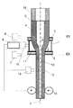
図1による装置は、工具を使用することなく中空円筒体4の伸長を可能にする。装置は、抵抗型加熱炉を備え、それは、垂直に向けられた加熱管1から本質的に構成され、加熱管1は、横断面が円形である加熱空間3を取り囲んでいる。加熱管1は、内径が240mm、外径が260mm、長さが180mmである環状要素からなる。加熱管1は、灰分の含有量が低いグラファイトからなる。グラファイトの加熱管1は、加熱ゾーンを適切に包囲している。加熱管1は、幅が55mmでありグラファイト管からなる延長部5によって、両側が拡張されている。この延長部5は、内径が250mmであり外径が280mmである。延長部5の壁の厚さが比較的大きく且つその中空円筒体の外面からの距離が比較的大きいため、中空円筒体4に作用する温度は、延長部5の領域において、加熱ゾーンの領域における最大温度より50℃超だけ低い。したがって、加熱ゾーンの内部容積Vcは約8140mm3である。
The device according to FIG. 1 enables the
上部検出面E1の高さに(上部延長部5の上縁に)、中空円筒体1の表面温度を検出する高温計6が配置されている。下部検出面E2の高さに(下部延長部5の下縁に)、伸長した管状ストランド12の表面温度を検出するさらなる高温計7が配置されている。高温計6および7の温度測定値ならびに高温計16によって測定される加熱管1の温度は、各々、コンピュータ8に送られる。
A
中空円筒体4の上端は、溶接部9を介して石英ガラス保持管10に接続されており、その石英ガラス保持管10によって、中空円筒体4は水平方向および垂直方向に移動可能である。
The upper end of the hollow
中空円筒体4は、その長手方向軸が、加熱管1の中心軸2に対して可能な限り同軸に延在するように向けられている。中空円筒体4は、上方から(その下端で開始して)加熱空間3に一定の送り速度で供給され、そこで軟化する。延伸球状部11を形成するように、軟化領域から管状ストランド12が垂直に引き取られる。ここで、管状ストランド12は、同様にコンピュータ8に接続されている壁厚さ測定装置14に沿って案内される。それにより、延伸プロセスにおいて、引き取られる管状ストランド12の壁厚さを記録し、コンピュータ8によって評価することができる。中空円筒体4および管状ストランド12の連続した内部ボアには、参照数字13が記載されている。チューブ引取り速度は、引取り装置を用いて検出され、コンピュータ8によって調整される。
The
ここで、石英ガラス管を製造する本発明の垂直延伸方法を行う実施形態について、図1の装置を参照してより詳細に説明する。 Here, an embodiment for performing the vertical stretching method of the present invention for producing a quartz glass tube will be described in more detail with reference to the apparatus of FIG.
中空円筒体の製造
標準OVD(外部蒸着)法を用いて、長手方向軸を中心に回転する支持体上で堆積バーナを往復運動させることにより、SiO2スート粒子を層毎に堆積させる。堆積プロセスが完了し支持体を取り除いた後、SiO2スートの多孔管が得られる。それに対して、製造プロセスによって導入されたヒドロキシル基を除去するための脱水処理を施す。ここで、スート管を、脱水炉内に垂直向きで導入し、最初に、塩素含有雰囲気において850℃〜約1000℃の範囲の温度で処理する。6時間の処理期間の後、スート材料で100重量ppm未満のヒドロキシル基濃度が得られる。
Production of hollow cylinders Using a standard OVD (external vapor deposition) method, SiO 2 soot particles are deposited layer by layer by reciprocating a deposition burner on a support rotating about a longitudinal axis. After the deposition process is complete and the support is removed, a porous tube of SiO 2 soot is obtained. On the other hand, a dehydration treatment is performed to remove hydroxyl groups introduced by the production process. Here, the soot tube is introduced vertically into the dehydration furnace and first treated at a temperature in the range of 850 ° C. to about 1000 ° C. in a chlorine-containing atmosphere. After a treatment period of 6 hours, hydroxyl group concentrations of less than 100 ppm by weight are obtained with the soot material.
このように処理されたスート管を、ガラス化炉において、内部ボアがつぶれることなく約1350℃の範囲の温度でガラス化する。このように製造された合成石英ガラスの管状石英ガラスブランクの2つの端部を切り取り、80番の丸砥石が備えられた外周研削盤によって、外壁を粗く研削する。それにより、所定の目標外径が主に得られる。その後、NC外周研削盤を用いて、管の外面を精密に研削する。それによって得られる管の内部ボアを、80番の砥石が備えられたホーニング機を用いて、平滑度を連続的に精密にして、全体的にホーニング加工し、最終処理を800番の砥石を用いて行う。その後、中空円筒体を、30%フッ化水素酸エッチング溶液で短時間エッチングする。そこで、平均表面粗さRzは、内壁の領域では5.5μmであり、外壁の領域では100μmである。
The soot tube thus treated is vitrified in a vitrification furnace at a temperature in the range of about 1350 ° C. without collapsing the internal bore. Two ends of the synthetic quartz glass tubular quartz glass blank produced in this way are cut out, and the outer wall is roughly ground by an outer peripheral grinding machine equipped with a
それにより、合成石英ガラスから、半径方向寸法の異なる中空円筒体を作製した。寸法を表1に列挙している。 Thereby, hollow cylindrical bodies having different radial dimensions were produced from synthetic quartz glass. The dimensions are listed in Table 1.
サブストレート管の製造
伸長プロセスを用いてサブストレート管を製造するために中空円筒体を使用し、これについて以下に例を参照して説明する。
Fabrication of substrate tube A hollow cylinder is used to fabricate a substrate tube using an elongation process, which will be described below with reference to an example.
垂直に向けられた加熱管1において、外径が200mmであり内径が50mmである石英ガラス中空円筒体4を、その長手方向軸が加熱管1の中心軸2に対して同軸に延在するように調整する。その後、加熱管1の中心軸2に配置される石英ガラスの中空円筒体4を、加熱管1内に所与の送り速度で放出し、20kg/hの質量スループットが得られるようにする。加熱ゾーンにおいて、中空円筒体4を、2,200℃を超える温度まで加熱する。発生した延伸球状部11から液性ガラスの管状ストランド12を、制御された延伸速度で、40mmの名目外径および36mmの内径(壁厚さ:2mm)になるように引き取る。中空円筒体4、延伸球状部11および管状ストランド12は、加熱空間容積VHeiz(約8,100mm3)の加熱ゾーン3内で、約2700mm3の総円筒体空間容積を占有する。
In the
延伸プロセス中、パージガスライン(図には示さず)を介して内部ボア13内に窒素流を導入する。窒素流は、内部ボア13内で700Pa(7mbar)の吹込圧が設定されるような大きさである。吹込圧を連続的に測定し、それに従って、窒素流の流量を再調整する。管状ストランド12の下端を部分的に閉鎖する栓を用いることにより、窒素流の妨げのない流出を阻止することができ、流量を約30l/分に制限することができる。これは、ガス流によって管状ストランド12の内壁が過度に冷却されることが回避され、平均粗さ値Rz=0.10μmで特徴付けられる平滑な溶融面が得られるという結果をもたらす(表1:サンプル1)。
During the drawing process, a nitrogen stream is introduced into the
プロセス制御を用いて、引き取られた管状ストランド12の外径および壁厚さを制御する。内部ボア13内の吹込圧は、壁厚さに対する制御変量としての役割を果たす。吹込圧は主に窒素流からもたらされ、それにより、寸法が変化したとき、制御ユニットを用いて窒素流の量が調整される。
Process control is used to control the outer diameter and wall thickness of the drawn
表1に述べるパラメータを用いるさらなる延伸試験を行った。それは、サンプル1を参照して上で説明した手順に類似する手順により、特に、伸長プロセス前に中空円筒体の機械的処理に対して、表1に示すパラメータを用いて行った。20kg/hのサンプル1の質量スループットとは対照的に、管状ストランドの名目外径が35mmを超えるサンプルにおいて、質量スループットを40kg/hに設定した。サンプル9では、質量スループットをさらに50kg/hに設定した。
Further stretching tests were performed using the parameters described in Table 1. It was performed by a procedure similar to that described above with reference to
管の曲げの測定
各管状ストランド12から、所望のサブストレート管長の区画を切り離す。回転軸が画定された旋盤に、管片の端部を締め付ける。回転軸を中心に回転している管片に対して、管径を越えて拡張したレーザビームを用いて、回転軸に対して垂直な方向に照明する。レーザビームの陰影が、各円周方向の位置に対して、管の外径とそれぞれの軸方向測定点(M)における(外径の半分としての)管中心点の位置とをもたらす。回転軸と軸方向測定点の管中心点との間の最大オフセット値(Max(Bow)M)を記憶する。全管片を測定するまで、軸方向測定点を管片の長手方向軸に沿って75mm刻みでシフトさせる。すべての測定点の最大オフセット値(Max(Bow)M)から最大オフセット(Bowmax)を求める。次に、以下の式:曲げ(mm/mm)=Bowmax(mm)/L(m)に基づいて、管片長(L)を考慮する管片のたわみの1メートル標準化計算を行う。
Tube Bend Measurement A section of the desired substrate tube length is cut from each
中空円筒体4から得られる管片はそれぞれのバッチを形成する。表1の最後の列に示す曲げ値は、対象バッチの中央値、すなわち、サイズに従って分類されたリストにおける中央の値を表す。
The tube pieces obtained from the
粗さパラメータRzの測定
DIN EN ISO4287に従って、個々の測定区画内の最高輪郭頂部と最深輪郭谷部の高さの差として、粗さパラメータRzを求める。Rzは、5つの測定区画の算術平均である。
Measurement of the roughness parameter R z According to DIN EN ISO 4287, the roughness parameter R z is determined as the difference in height between the highest contour top and the deepest contour valley in each measurement section. R z is the arithmetic mean of the five measurement zones.
測定結果
MCVD法を用いてまたは別のプラズマ型内部堆積法に基づいて、内壁の上にSiO2層を堆積させるためのサブストレート管として、管状ストランドセグメントを用いる。比較的安価な製造パラメータであるにも関わらず、サブストレート管は、特にたわみが小さいことにより、十分に平滑な内面および高い寸法安定性によって特徴付けられる。それは特に、石英ガラスの厚壁の出発円筒体の使用と、中空円筒体の内壁および外壁のそれほど複雑ではない機械的仕上げとによる。0.7mm/m以下の曲げと、Rz値が0.15μm以下である内面の粗さとは、許容可能であると考えられる。
Measurement results based on MCVD method or another plasma-type internal deposition method using, as a substrate tube for depositing an SiO 2 layer on the inner wall, using tubular strand segments. Despite being a relatively inexpensive manufacturing parameter, the substrate tube is characterized by a sufficiently smooth inner surface and high dimensional stability, particularly due to its low deflection. It is in particular due to the use of a quartz glass thick-walled starting cylinder and a less complex mechanical finish of the inner and outer walls of the hollow cylinder. Bending of 0.7 mm / m or less and the roughness of the inner surface with an R z value of 0.15 μm or less are considered acceptable.
プロセスパラメータおよび結果に関する詳細は表1に記載しており、そこでは、
Ca 中空円筒体の外径
Ci 中空円筒体の内径
TA 管状ストランドの名目外径
TI 管状ストランドの名目内径
CR 直径比Ca/Ci
TR 直径比Ta/Ti
A(C)=中空円筒体の内面
A(T)=管の内面
L(C)=中空円筒体の長さ
L(T)=管状ストランドの長さ
である。
Details regarding the process parameters and results are given in Table 1, where:
C a Outer diameter of hollow cylinder C i Inner diameter of hollow cylinder T Nominal outer diameter of T A tubular strand T I Nominal inner diameter of C tubular strand C R diameter ratio C a / C i
T R diameter ratio T a / T i
A (C) = inner surface of hollow cylinder A (T) = inner surface of tube L (C) = length of hollow cylinder L (T) = length of tubular strand.
国際公開第2004/083141A1号に示すように、形状および延伸パラメータ基づいて参照サンプルを製造した(表1、行1)。サンプル2、4、6、8および9は、さらなる比較サンプルを表している。本発明のものから逸脱しているパラメータは、表において灰色の背景を有している。表に示すように、出発円筒体の小さい直径比(Cr<3)は、通常、内面の比A(T)/A(C)によって表される小さい成形度合いによって達成され、すなわち、それは、延伸比(L(T)/L(C))が比較的大きい場合であっても達成される。しかしながら、参照として与えられた中空円筒体の仕上げ処理において、これにより、比較サンプル4、6および9に示すように、引き取られた管状ストランドの内面に許容できない粗さがもたらされる。対照的に、サンプル2および8は、許容可能な粗さを示すが、たわみの増大を示し、それは、中空円筒体および管状ストランドの内径の差が大きいこと、すなわち、比Ci/Tiおよび半径方向における付随する成形度合いに帰する可能性がある。
Reference samples were produced based on shape and stretch parameters as shown in WO 2004 / 083141A1 (Table 1, Row 1).
Claims (12)
Ca>180mm、
Cr=Ca/CiとしてCr>3、
Tr=Ta/TiとしてTr<1.6、および
Ci/Ti<2.5
が適用可能である、方法。 A method for producing a quartz glass substrate tube, comprising continuously supplying a hollow cylindrical body of quartz glass having an outer diameter C a , an inner diameter C i and an inner bore to the heating zone (3), includes a possible softening the hollow cylinder in each zone in the heating zone (3), the softening part, and that taking up a tubular strand (12) having an outer diameter T a and the inner diameter T i, said internal bore (13 ), A blowing pressure set in the range of 400 to 1000 Pa (4 to 10 mbar) is generated, and for hollow cylinders (4) and tubular strands (12):
C a > 180 mm,
C r = C a / C i as C r> 3,
T r = T a / T i as T r <1.6, and C i / T i <2.5
Is applicable.
Ca<300mm、および
Ci/Ti<2
が適用可能であることを特徴とする、請求項1に記載の方法。 The blowing pressure is set in the range of 600 to 800 Pa (6 to 8 mbar), and for the hollow cylindrical body:
C a <300 mm and C i / T i <2
The method according to claim 1, characterized in that is applicable.
28<Ta<50、および
Tr<1.3
が適用可能であることを特徴とする、請求項1または2に記載の方法。 For the tubular strand:
28 <T a <50, and T r <1.3
The method according to claim 1 or 2, characterized in that is applicable.
3.5<Cr<4.5、および
Cr>Tr+2.4
が適用可能であることを特徴とする、請求項1〜3のいずれか一項に記載の方法。 For hollow cylinders and tubular strands:
3.5 <C r <4.5, and C r > T r +2.4
The method according to any one of claims 1 to 3, characterized in that is applicable.
Applications Claiming Priority (2)
| Application Number | Priority Date | Filing Date | Title |
|---|---|---|---|
| EP15175343.1 | 2015-07-03 | ||
| EP15175343.1A EP3112323B1 (en) | 2015-07-03 | 2015-07-03 | Method for producing a substrate pipe made of quartz glass |
Publications (2)
| Publication Number | Publication Date |
|---|---|
| JP2017014099A true JP2017014099A (en) | 2017-01-19 |
| JP6814511B2 JP6814511B2 (en) | 2021-01-20 |
Family
ID=53510803
Family Applications (1)
| Application Number | Title | Priority Date | Filing Date |
|---|---|---|---|
| JP2016125433A Active JP6814511B2 (en) | 2015-07-03 | 2016-06-24 | How to make a quartz glass substrate tube |
Country Status (5)
| Country | Link |
|---|---|
| US (1) | US10322962B2 (en) |
| EP (1) | EP3112323B1 (en) |
| JP (1) | JP6814511B2 (en) |
| KR (1) | KR102539239B1 (en) |
| CN (1) | CN106316082B (en) |
Cited By (2)
| Publication number | Priority date | Publication date | Assignee | Title |
|---|---|---|---|---|
| JPWO2018131499A1 (en) * | 2017-01-11 | 2019-07-11 | 信越石英株式会社 | Method for producing hollow porous quartz glass base material |
| JP7453331B2 (en) | 2019-07-17 | 2024-03-19 | ヘレーウス クヴァルツグラース ゲゼルシャフト ミット ベシュレンクテル ハフツング ウント コンパニー コマンディートゲゼルシャフト | Method for manufacturing hollow core fiber and method for manufacturing preform for hollow core fiber |
Families Citing this family (4)
| Publication number | Priority date | Publication date | Assignee | Title |
|---|---|---|---|---|
| EP3636607B1 (en) * | 2018-10-09 | 2021-01-13 | Heraeus Quarzglas GmbH & Co. KG | Method for manufacturing a capillary tube |
| CN109608032B (en) * | 2018-12-26 | 2021-11-26 | 南京华信藤仓光通信有限公司 | Rod conveying device of resistance furnace for hanging round-handle rod |
| EP4067315A1 (en) * | 2021-03-29 | 2022-10-05 | Heraeus Quarzglas GmbH & Co. KG | Quartz glass tube and method of manufacturing the same |
| CN113213748B (en) * | 2021-04-28 | 2022-05-06 | 中国科学院西安光学精密机械研究所 | Preparation method of high-strength quartz optical fiber |
Family Cites Families (13)
| Publication number | Priority date | Publication date | Assignee | Title |
|---|---|---|---|---|
| DK0598349T3 (en) * | 1992-11-19 | 1999-04-26 | Shinetsu Quartz Prod | Process for producing a large quartz glass tube, as well as a preform and an optical fiber |
| JP2980501B2 (en) * | 1992-11-19 | 1999-11-22 | 信越石英株式会社 | Large quartz glass tube, large quartz glass preform, and methods for producing them |
| DE19856892C2 (en) * | 1998-12-10 | 2001-03-15 | Heraeus Quarzglas | Process for the production of a tube made of glassy material, in particular quartz glass |
| DE10393680B4 (en) * | 2003-03-21 | 2009-03-26 | Heraeus Quarzglas Gmbh & Co. Kg | Synthetic quartz glass tube for the manufacture of a preform, process for its manufacture in a vertical drawing process and use of the tube |
| DE10333059A1 (en) * | 2003-07-18 | 2005-02-17 | Heraeus Tenevo Ag | Method for producing an optical component made of quartz glass and hollow cylinder made of quartz glass for carrying out the method |
| DE10357063B3 (en) * | 2003-12-04 | 2005-04-21 | Heraeus Tenevo Ag | Vertical drawing of glass, comprises continuously supplying a glass cylinder containing a vertical heating tube to a heating zone, softening, drawing and cutting |
| DE102004050515B4 (en) * | 2004-10-15 | 2007-08-02 | Heraeus Tenevo Gmbh | Method for producing tubes of quartz glass |
| JP2006294440A (en) * | 2005-04-12 | 2006-10-26 | Shinetsu Quartz Prod Co Ltd | Deformed synthetic quartz tube for excimer uv lamp, and its manufacturing method |
| DE102005028219B3 (en) * | 2005-05-16 | 2006-10-12 | Heraeus Tenevo Gmbh | Quartz glass tube, is produced by elongating a hollow glass cylinder by continuously feeding it to a heating zone with a vertical heating tube |
| JP2007320803A (en) * | 2006-05-31 | 2007-12-13 | Sumitomo Electric Ind Ltd | Method for manufacturing glass pipe |
| DE102007003889B3 (en) * | 2007-01-19 | 2008-09-11 | Heraeus Quarzglas Gmbh & Co. Kg | Quartz glass tube as a semi-finished product for the preform and fiber production, its use and method for producing the quartz glass tube |
| DE102009014418B3 (en) * | 2009-03-26 | 2010-04-15 | Heraeus Quarzglas Gmbh & Co. Kg | Drawing method for the production of cylindrical components made of quartz glass |
| DE102011116806A1 (en) * | 2011-10-25 | 2013-04-25 | Heraeus Quarzglas Gmbh & Co. Kg | Method for producing a cylindrical glass component by elongation |
-
2015
- 2015-07-03 EP EP15175343.1A patent/EP3112323B1/en active Active
-
2016
- 2016-06-24 JP JP2016125433A patent/JP6814511B2/en active Active
- 2016-06-29 US US15/197,245 patent/US10322962B2/en active Active
- 2016-06-30 KR KR1020160082881A patent/KR102539239B1/en active IP Right Grant
- 2016-07-01 CN CN201610510309.4A patent/CN106316082B/en active Active
Cited By (2)
| Publication number | Priority date | Publication date | Assignee | Title |
|---|---|---|---|---|
| JPWO2018131499A1 (en) * | 2017-01-11 | 2019-07-11 | 信越石英株式会社 | Method for producing hollow porous quartz glass base material |
| JP7453331B2 (en) | 2019-07-17 | 2024-03-19 | ヘレーウス クヴァルツグラース ゲゼルシャフト ミット ベシュレンクテル ハフツング ウント コンパニー コマンディートゲゼルシャフト | Method for manufacturing hollow core fiber and method for manufacturing preform for hollow core fiber |
Also Published As
| Publication number | Publication date |
|---|---|
| CN106316082B (en) | 2020-01-03 |
| JP6814511B2 (en) | 2021-01-20 |
| KR20170004886A (en) | 2017-01-11 |
| CN106316082A (en) | 2017-01-11 |
| KR102539239B1 (en) | 2023-06-01 |
| EP3112323A1 (en) | 2017-01-04 |
| US10322962B2 (en) | 2019-06-18 |
| US20170001901A1 (en) | 2017-01-05 |
| EP3112323B1 (en) | 2021-09-01 |
Similar Documents
| Publication | Publication Date | Title |
|---|---|---|
| JP6814511B2 (en) | How to make a quartz glass substrate tube | |
| JP6478990B2 (en) | Manufacturing method for large quartz glass tubes | |
| JP5352231B2 (en) | Method for producing a quartz glass tube by stretching a hollow cylinder of quartz glass | |
| TWI668193B (en) | Method for producing a tube of glass | |
| CN104245610B (en) | The method being prepared cylinder shape assembly by fluorine-containing synthetic quartz glass | |
| US20060174659A1 (en) | method for production of an optical component made from quartz glass and hollow cylinder made from quartz glass for carrying out said method | |
| JP4229442B2 (en) | Method for producing a tube made of quartz glass, tubular intermediate product made of porous quartz glass, and use thereof | |
| JP5448361B2 (en) | Apparatus and method for manufacturing optical preforms | |
| US9738558B2 (en) | Processing method of glass base material for optical fiber | |
| US20070209400A1 (en) | Method For Producing An Optical Component | |
| EP1487750B1 (en) | Method for producing an optical fiber and optical fiber | |
| US7712335B2 (en) | Quartz glass cylinder for production of an optical component and method for production thereof | |
| US8544299B2 (en) | Quartz glass tube as a semifinished product for preform and fiber manufacture, and method for making the quartz glass tube | |
| US4298364A (en) | Method of making optical fibers having improved core roundness | |
| JP6459585B2 (en) | Optical fiber preform manufacturing method | |
| US20090260400A1 (en) | Method for Producing a Tubular Semifinished Product From Fluorine-Doped Quartz Glass | |
| US20040107734A1 (en) | Systems and methods for fabricating optical fiber preforms | |
| JP2013006750A (en) | Method for production of optical fiber | |
| KR100966585B1 (en) | Method of manufacturing a solid perform | |
| US20060150685A1 (en) | Method for elongating and collapsing a blank made of quartz glass | |
| JP2009161392A (en) | Production method of glass preform for optical fiber, and optical fiber | |
| WO2000078686A1 (en) | Production method for optical fiber base material | |
| WO2004101457A1 (en) | Process for producing glass parent material of optical fiber | |
| JP2003095685A (en) | Optical fiber preform and its manufacturing method | |
| JP2007008763A (en) | Manufacturing method of quartz glass tube and manufacturing unit |
Legal Events
| Date | Code | Title | Description |
|---|---|---|---|
| A621 | Written request for application examination |
Free format text: JAPANESE INTERMEDIATE CODE: A621 Effective date: 20190307 |
|
| A977 | Report on retrieval |
Free format text: JAPANESE INTERMEDIATE CODE: A971007 Effective date: 20200213 |
|
| A131 | Notification of reasons for refusal |
Free format text: JAPANESE INTERMEDIATE CODE: A131 Effective date: 20200225 |
|
| A601 | Written request for extension of time |
Free format text: JAPANESE INTERMEDIATE CODE: A601 Effective date: 20200525 |
|
| A521 | Request for written amendment filed |
Free format text: JAPANESE INTERMEDIATE CODE: A523 Effective date: 20200714 |
|
| TRDD | Decision of grant or rejection written | ||
| A01 | Written decision to grant a patent or to grant a registration (utility model) |
Free format text: JAPANESE INTERMEDIATE CODE: A01 Effective date: 20201201 |
|
| A61 | First payment of annual fees (during grant procedure) |
Free format text: JAPANESE INTERMEDIATE CODE: A61 Effective date: 20201218 |
|
| R150 | Certificate of patent or registration of utility model |
Ref document number: 6814511 Country of ref document: JP Free format text: JAPANESE INTERMEDIATE CODE: R150 |
|
| S531 | Written request for registration of change of domicile |
Free format text: JAPANESE INTERMEDIATE CODE: R313531 |
|
| R350 | Written notification of registration of transfer |
Free format text: JAPANESE INTERMEDIATE CODE: R350 |
|
| R250 | Receipt of annual fees |
Free format text: JAPANESE INTERMEDIATE CODE: R250 |