JP2017014094A - Dielectric ceramic composition and multilayer ceramic capacitor containing the same - Google Patents
Dielectric ceramic composition and multilayer ceramic capacitor containing the same Download PDFInfo
- Publication number
- JP2017014094A JP2017014094A JP2016069162A JP2016069162A JP2017014094A JP 2017014094 A JP2017014094 A JP 2017014094A JP 2016069162 A JP2016069162 A JP 2016069162A JP 2016069162 A JP2016069162 A JP 2016069162A JP 2017014094 A JP2017014094 A JP 2017014094A
- Authority
- JP
- Japan
- Prior art keywords
- dielectric
- ceramic composition
- subcomponent
- base material
- multilayer ceramic
- Prior art date
- Legal status (The legal status is an assumption and is not a legal conclusion. Google has not performed a legal analysis and makes no representation as to the accuracy of the status listed.)
- Granted
Links
- 239000000919 ceramic Substances 0.000 title claims abstract description 54
- 239000000203 mixture Substances 0.000 title claims abstract description 46
- 239000003985 ceramic capacitor Substances 0.000 title claims abstract description 40
- 239000000463 material Substances 0.000 claims abstract description 58
- 239000000843 powder Substances 0.000 claims abstract description 44
- 230000005684 electric field Effects 0.000 claims description 20
- BVKZGUZCCUSVTD-UHFFFAOYSA-L Carbonate Chemical compound [O-]C([O-])=O BVKZGUZCCUSVTD-UHFFFAOYSA-L 0.000 claims description 11
- 229910052692 Dysprosium Inorganic materials 0.000 claims description 7
- 239000011521 glass Substances 0.000 claims description 7
- 229910052727 yttrium Inorganic materials 0.000 claims description 7
- 229910052802 copper Inorganic materials 0.000 claims description 6
- 229910052759 nickel Inorganic materials 0.000 claims description 6
- 229910052684 Cerium Inorganic materials 0.000 claims description 5
- 229910052688 Gadolinium Inorganic materials 0.000 claims description 5
- 229910052689 Holmium Inorganic materials 0.000 claims description 5
- 229910052779 Neodymium Inorganic materials 0.000 claims description 5
- 229910052772 Samarium Inorganic materials 0.000 claims description 5
- 229910052746 lanthanum Inorganic materials 0.000 claims description 5
- 229910052804 chromium Inorganic materials 0.000 claims description 4
- 150000001875 compounds Chemical class 0.000 claims description 4
- 229910052742 iron Inorganic materials 0.000 claims description 4
- 229910052748 manganese Inorganic materials 0.000 claims description 4
- 229910052720 vanadium Inorganic materials 0.000 claims description 4
- 229910052725 zinc Inorganic materials 0.000 claims description 4
- 229910052691 Erbium Inorganic materials 0.000 claims description 3
- 229910052573 porcelain Inorganic materials 0.000 claims 2
- 230000008859 change Effects 0.000 description 23
- 229910004298 SiO 2 Inorganic materials 0.000 description 13
- 230000000052 comparative effect Effects 0.000 description 13
- 230000007423 decrease Effects 0.000 description 13
- 239000003990 capacitor Substances 0.000 description 12
- PXHVJJICTQNCMI-UHFFFAOYSA-N nickel Substances [Ni] PXHVJJICTQNCMI-UHFFFAOYSA-N 0.000 description 10
- 238000009413 insulation Methods 0.000 description 7
- 239000010949 copper Substances 0.000 description 6
- 238000010304 firing Methods 0.000 description 6
- 239000003989 dielectric material Substances 0.000 description 4
- KDLHZDBZIXYQEI-UHFFFAOYSA-N Palladium Chemical compound [Pd] KDLHZDBZIXYQEI-UHFFFAOYSA-N 0.000 description 3
- YXFVVABEGXRONW-UHFFFAOYSA-N Toluene Chemical compound CC1=CC=CC=C1 YXFVVABEGXRONW-UHFFFAOYSA-N 0.000 description 3
- 239000004020 conductor Substances 0.000 description 3
- 238000004519 manufacturing process Methods 0.000 description 3
- 239000002245 particle Substances 0.000 description 3
- 239000012071 phase Substances 0.000 description 3
- 238000005245 sintering Methods 0.000 description 3
- 238000012360 testing method Methods 0.000 description 3
- RYGMFSIKBFXOCR-UHFFFAOYSA-N Copper Chemical compound [Cu] RYGMFSIKBFXOCR-UHFFFAOYSA-N 0.000 description 2
- LFQSCWFLJHTTHZ-UHFFFAOYSA-N Ethanol Chemical compound CCO LFQSCWFLJHTTHZ-UHFFFAOYSA-N 0.000 description 2
- MCMNRKCIXSYSNV-UHFFFAOYSA-N Zirconium dioxide Chemical compound O=[Zr]=O MCMNRKCIXSYSNV-UHFFFAOYSA-N 0.000 description 2
- 230000005534 acoustic noise Effects 0.000 description 2
- 239000000956 alloy Substances 0.000 description 2
- 229910045601 alloy Inorganic materials 0.000 description 2
- 239000012298 atmosphere Substances 0.000 description 2
- 230000008901 benefit Effects 0.000 description 2
- 230000015556 catabolic process Effects 0.000 description 2
- 229910010293 ceramic material Inorganic materials 0.000 description 2
- 238000006731 degradation reaction Methods 0.000 description 2
- 238000013461 design Methods 0.000 description 2
- 238000002474 experimental method Methods 0.000 description 2
- 238000012986 modification Methods 0.000 description 2
- 230000004048 modification Effects 0.000 description 2
- 229910000510 noble metal Inorganic materials 0.000 description 2
- 230000009467 reduction Effects 0.000 description 2
- IJGRMHOSHXDMSA-UHFFFAOYSA-N Atomic nitrogen Chemical compound N#N IJGRMHOSHXDMSA-UHFFFAOYSA-N 0.000 description 1
- BQCADISMDOOEFD-UHFFFAOYSA-N Silver Chemical compound [Ag] BQCADISMDOOEFD-UHFFFAOYSA-N 0.000 description 1
- 229910010413 TiO 2 Inorganic materials 0.000 description 1
- 230000002411 adverse Effects 0.000 description 1
- 230000032683 aging Effects 0.000 description 1
- 229910002113 barium titanate Inorganic materials 0.000 description 1
- JRPBQTZRNDNNOP-UHFFFAOYSA-N barium titanate Chemical compound [Ba+2].[Ba+2].[O-][Ti]([O-])([O-])[O-] JRPBQTZRNDNNOP-UHFFFAOYSA-N 0.000 description 1
- 239000011230 binding agent Substances 0.000 description 1
- 230000015572 biosynthetic process Effects 0.000 description 1
- 150000004649 carbonic acid derivatives Chemical class 0.000 description 1
- 239000000470 constituent Substances 0.000 description 1
- 239000013078 crystal Substances 0.000 description 1
- 239000002270 dispersing agent Substances 0.000 description 1
- 230000000694 effects Effects 0.000 description 1
- 238000010438 heat treatment Methods 0.000 description 1
- 229910021645 metal ion Inorganic materials 0.000 description 1
- 238000000034 method Methods 0.000 description 1
- 229910052757 nitrogen Inorganic materials 0.000 description 1
- 239000012299 nitrogen atmosphere Substances 0.000 description 1
- 238000007254 oxidation reaction Methods 0.000 description 1
- 229910052763 palladium Inorganic materials 0.000 description 1
- 230000008569 process Effects 0.000 description 1
- 239000002994 raw material Substances 0.000 description 1
- 229910052709 silver Inorganic materials 0.000 description 1
- 239000004332 silver Substances 0.000 description 1
- 239000002002 slurry Substances 0.000 description 1
- 238000010532 solid phase synthesis reaction Methods 0.000 description 1
- 239000006104 solid solution Substances 0.000 description 1
- 239000007858 starting material Substances 0.000 description 1
- 239000010409 thin film Substances 0.000 description 1
Images


Classifications
-
- C—CHEMISTRY; METALLURGY
- C04—CEMENTS; CONCRETE; ARTIFICIAL STONE; CERAMICS; REFRACTORIES
- C04B—LIME, MAGNESIA; SLAG; CEMENTS; COMPOSITIONS THEREOF, e.g. MORTARS, CONCRETE OR LIKE BUILDING MATERIALS; ARTIFICIAL STONE; CERAMICS; REFRACTORIES; TREATMENT OF NATURAL STONE
- C04B35/00—Shaped ceramic products characterised by their composition; Ceramics compositions; Processing powders of inorganic compounds preparatory to the manufacturing of ceramic products
- C04B35/01—Shaped ceramic products characterised by their composition; Ceramics compositions; Processing powders of inorganic compounds preparatory to the manufacturing of ceramic products based on oxide ceramics
- C04B35/48—Shaped ceramic products characterised by their composition; Ceramics compositions; Processing powders of inorganic compounds preparatory to the manufacturing of ceramic products based on oxide ceramics based on zirconium or hafnium oxides, zirconates, zircon or hafnates
- C04B35/49—Shaped ceramic products characterised by their composition; Ceramics compositions; Processing powders of inorganic compounds preparatory to the manufacturing of ceramic products based on oxide ceramics based on zirconium or hafnium oxides, zirconates, zircon or hafnates containing also titanium oxides or titanates
-
- C—CHEMISTRY; METALLURGY
- C01—INORGANIC CHEMISTRY
- C01G—COMPOUNDS CONTAINING METALS NOT COVERED BY SUBCLASSES C01D OR C01F
- C01G25/00—Compounds of zirconium
- C01G25/006—Compounds containing, besides zirconium, two or more other elements, with the exception of oxygen or hydrogen
-
- H—ELECTRICITY
- H01—ELECTRIC ELEMENTS
- H01G—CAPACITORS; CAPACITORS, RECTIFIERS, DETECTORS, SWITCHING DEVICES OR LIGHT-SENSITIVE DEVICES, OF THE ELECTROLYTIC TYPE
- H01G4/00—Fixed capacitors; Processes of their manufacture
- H01G4/002—Details
- H01G4/018—Dielectrics
- H01G4/06—Solid dielectrics
- H01G4/08—Inorganic dielectrics
- H01G4/12—Ceramic dielectrics
- H01G4/1209—Ceramic dielectrics characterised by the ceramic dielectric material
- H01G4/1218—Ceramic dielectrics characterised by the ceramic dielectric material based on titanium oxides or titanates
- H01G4/1227—Ceramic dielectrics characterised by the ceramic dielectric material based on titanium oxides or titanates based on alkaline earth titanates
-
- H—ELECTRICITY
- H01—ELECTRIC ELEMENTS
- H01G—CAPACITORS; CAPACITORS, RECTIFIERS, DETECTORS, SWITCHING DEVICES OR LIGHT-SENSITIVE DEVICES, OF THE ELECTROLYTIC TYPE
- H01G4/00—Fixed capacitors; Processes of their manufacture
- H01G4/002—Details
- H01G4/018—Dielectrics
- H01G4/06—Solid dielectrics
- H01G4/08—Inorganic dielectrics
- H01G4/12—Ceramic dielectrics
- H01G4/1209—Ceramic dielectrics characterised by the ceramic dielectric material
- H01G4/1236—Ceramic dielectrics characterised by the ceramic dielectric material based on zirconium oxides or zirconates
- H01G4/1245—Ceramic dielectrics characterised by the ceramic dielectric material based on zirconium oxides or zirconates containing also titanates
-
- H—ELECTRICITY
- H01—ELECTRIC ELEMENTS
- H01G—CAPACITORS; CAPACITORS, RECTIFIERS, DETECTORS, SWITCHING DEVICES OR LIGHT-SENSITIVE DEVICES, OF THE ELECTROLYTIC TYPE
- H01G4/00—Fixed capacitors; Processes of their manufacture
- H01G4/30—Stacked capacitors
-
- C—CHEMISTRY; METALLURGY
- C04—CEMENTS; CONCRETE; ARTIFICIAL STONE; CERAMICS; REFRACTORIES
- C04B—LIME, MAGNESIA; SLAG; CEMENTS; COMPOSITIONS THEREOF, e.g. MORTARS, CONCRETE OR LIKE BUILDING MATERIALS; ARTIFICIAL STONE; CERAMICS; REFRACTORIES; TREATMENT OF NATURAL STONE
- C04B2235/00—Aspects relating to ceramic starting mixtures or sintered ceramic products
- C04B2235/02—Composition of constituents of the starting material or of secondary phases of the final product
- C04B2235/30—Constituents and secondary phases not being of a fibrous nature
- C04B2235/32—Metal oxides, mixed metal oxides, or oxide-forming salts thereof, e.g. carbonates, nitrates, (oxy)hydroxides, chlorides
- C04B2235/3205—Alkaline earth oxides or oxide forming salts thereof, e.g. beryllium oxide
- C04B2235/3208—Calcium oxide or oxide-forming salts thereof, e.g. lime
-
- C—CHEMISTRY; METALLURGY
- C04—CEMENTS; CONCRETE; ARTIFICIAL STONE; CERAMICS; REFRACTORIES
- C04B—LIME, MAGNESIA; SLAG; CEMENTS; COMPOSITIONS THEREOF, e.g. MORTARS, CONCRETE OR LIKE BUILDING MATERIALS; ARTIFICIAL STONE; CERAMICS; REFRACTORIES; TREATMENT OF NATURAL STONE
- C04B2235/00—Aspects relating to ceramic starting mixtures or sintered ceramic products
- C04B2235/02—Composition of constituents of the starting material or of secondary phases of the final product
- C04B2235/30—Constituents and secondary phases not being of a fibrous nature
- C04B2235/32—Metal oxides, mixed metal oxides, or oxide-forming salts thereof, e.g. carbonates, nitrates, (oxy)hydroxides, chlorides
- C04B2235/3205—Alkaline earth oxides or oxide forming salts thereof, e.g. beryllium oxide
- C04B2235/3213—Strontium oxides or oxide-forming salts thereof
-
- C—CHEMISTRY; METALLURGY
- C04—CEMENTS; CONCRETE; ARTIFICIAL STONE; CERAMICS; REFRACTORIES
- C04B—LIME, MAGNESIA; SLAG; CEMENTS; COMPOSITIONS THEREOF, e.g. MORTARS, CONCRETE OR LIKE BUILDING MATERIALS; ARTIFICIAL STONE; CERAMICS; REFRACTORIES; TREATMENT OF NATURAL STONE
- C04B2235/00—Aspects relating to ceramic starting mixtures or sintered ceramic products
- C04B2235/02—Composition of constituents of the starting material or of secondary phases of the final product
- C04B2235/30—Constituents and secondary phases not being of a fibrous nature
- C04B2235/32—Metal oxides, mixed metal oxides, or oxide-forming salts thereof, e.g. carbonates, nitrates, (oxy)hydroxides, chlorides
- C04B2235/3224—Rare earth oxide or oxide forming salts thereof, e.g. scandium oxide
- C04B2235/3225—Yttrium oxide or oxide-forming salts thereof
-
- C—CHEMISTRY; METALLURGY
- C04—CEMENTS; CONCRETE; ARTIFICIAL STONE; CERAMICS; REFRACTORIES
- C04B—LIME, MAGNESIA; SLAG; CEMENTS; COMPOSITIONS THEREOF, e.g. MORTARS, CONCRETE OR LIKE BUILDING MATERIALS; ARTIFICIAL STONE; CERAMICS; REFRACTORIES; TREATMENT OF NATURAL STONE
- C04B2235/00—Aspects relating to ceramic starting mixtures or sintered ceramic products
- C04B2235/02—Composition of constituents of the starting material or of secondary phases of the final product
- C04B2235/30—Constituents and secondary phases not being of a fibrous nature
- C04B2235/32—Metal oxides, mixed metal oxides, or oxide-forming salts thereof, e.g. carbonates, nitrates, (oxy)hydroxides, chlorides
- C04B2235/3224—Rare earth oxide or oxide forming salts thereof, e.g. scandium oxide
- C04B2235/3227—Lanthanum oxide or oxide-forming salts thereof
-
- C—CHEMISTRY; METALLURGY
- C04—CEMENTS; CONCRETE; ARTIFICIAL STONE; CERAMICS; REFRACTORIES
- C04B—LIME, MAGNESIA; SLAG; CEMENTS; COMPOSITIONS THEREOF, e.g. MORTARS, CONCRETE OR LIKE BUILDING MATERIALS; ARTIFICIAL STONE; CERAMICS; REFRACTORIES; TREATMENT OF NATURAL STONE
- C04B2235/00—Aspects relating to ceramic starting mixtures or sintered ceramic products
- C04B2235/02—Composition of constituents of the starting material or of secondary phases of the final product
- C04B2235/30—Constituents and secondary phases not being of a fibrous nature
- C04B2235/32—Metal oxides, mixed metal oxides, or oxide-forming salts thereof, e.g. carbonates, nitrates, (oxy)hydroxides, chlorides
- C04B2235/3224—Rare earth oxide or oxide forming salts thereof, e.g. scandium oxide
- C04B2235/3229—Cerium oxides or oxide-forming salts thereof
-
- C—CHEMISTRY; METALLURGY
- C04—CEMENTS; CONCRETE; ARTIFICIAL STONE; CERAMICS; REFRACTORIES
- C04B—LIME, MAGNESIA; SLAG; CEMENTS; COMPOSITIONS THEREOF, e.g. MORTARS, CONCRETE OR LIKE BUILDING MATERIALS; ARTIFICIAL STONE; CERAMICS; REFRACTORIES; TREATMENT OF NATURAL STONE
- C04B2235/00—Aspects relating to ceramic starting mixtures or sintered ceramic products
- C04B2235/02—Composition of constituents of the starting material or of secondary phases of the final product
- C04B2235/30—Constituents and secondary phases not being of a fibrous nature
- C04B2235/32—Metal oxides, mixed metal oxides, or oxide-forming salts thereof, e.g. carbonates, nitrates, (oxy)hydroxides, chlorides
- C04B2235/3231—Refractory metal oxides, their mixed metal oxides, or oxide-forming salts thereof
- C04B2235/3239—Vanadium oxides, vanadates or oxide forming salts thereof, e.g. magnesium vanadate
-
- C—CHEMISTRY; METALLURGY
- C04—CEMENTS; CONCRETE; ARTIFICIAL STONE; CERAMICS; REFRACTORIES
- C04B—LIME, MAGNESIA; SLAG; CEMENTS; COMPOSITIONS THEREOF, e.g. MORTARS, CONCRETE OR LIKE BUILDING MATERIALS; ARTIFICIAL STONE; CERAMICS; REFRACTORIES; TREATMENT OF NATURAL STONE
- C04B2235/00—Aspects relating to ceramic starting mixtures or sintered ceramic products
- C04B2235/02—Composition of constituents of the starting material or of secondary phases of the final product
- C04B2235/30—Constituents and secondary phases not being of a fibrous nature
- C04B2235/32—Metal oxides, mixed metal oxides, or oxide-forming salts thereof, e.g. carbonates, nitrates, (oxy)hydroxides, chlorides
- C04B2235/3231—Refractory metal oxides, their mixed metal oxides, or oxide-forming salts thereof
- C04B2235/3241—Chromium oxides, chromates, or oxide-forming salts thereof
-
- C—CHEMISTRY; METALLURGY
- C04—CEMENTS; CONCRETE; ARTIFICIAL STONE; CERAMICS; REFRACTORIES
- C04B—LIME, MAGNESIA; SLAG; CEMENTS; COMPOSITIONS THEREOF, e.g. MORTARS, CONCRETE OR LIKE BUILDING MATERIALS; ARTIFICIAL STONE; CERAMICS; REFRACTORIES; TREATMENT OF NATURAL STONE
- C04B2235/00—Aspects relating to ceramic starting mixtures or sintered ceramic products
- C04B2235/02—Composition of constituents of the starting material or of secondary phases of the final product
- C04B2235/30—Constituents and secondary phases not being of a fibrous nature
- C04B2235/32—Metal oxides, mixed metal oxides, or oxide-forming salts thereof, e.g. carbonates, nitrates, (oxy)hydroxides, chlorides
- C04B2235/3231—Refractory metal oxides, their mixed metal oxides, or oxide-forming salts thereof
- C04B2235/3244—Zirconium oxides, zirconates, hafnium oxides, hafnates, or oxide-forming salts thereof
- C04B2235/3248—Zirconates or hafnates, e.g. zircon
- C04B2235/3249—Zirconates or hafnates, e.g. zircon containing also titanium oxide or titanates, e.g. lead zirconate titanate (PZT)
-
- C—CHEMISTRY; METALLURGY
- C04—CEMENTS; CONCRETE; ARTIFICIAL STONE; CERAMICS; REFRACTORIES
- C04B—LIME, MAGNESIA; SLAG; CEMENTS; COMPOSITIONS THEREOF, e.g. MORTARS, CONCRETE OR LIKE BUILDING MATERIALS; ARTIFICIAL STONE; CERAMICS; REFRACTORIES; TREATMENT OF NATURAL STONE
- C04B2235/00—Aspects relating to ceramic starting mixtures or sintered ceramic products
- C04B2235/02—Composition of constituents of the starting material or of secondary phases of the final product
- C04B2235/30—Constituents and secondary phases not being of a fibrous nature
- C04B2235/32—Metal oxides, mixed metal oxides, or oxide-forming salts thereof, e.g. carbonates, nitrates, (oxy)hydroxides, chlorides
- C04B2235/3262—Manganese oxides, manganates, rhenium oxides or oxide-forming salts thereof, e.g. MnO
- C04B2235/3267—MnO2
-
- C—CHEMISTRY; METALLURGY
- C04—CEMENTS; CONCRETE; ARTIFICIAL STONE; CERAMICS; REFRACTORIES
- C04B—LIME, MAGNESIA; SLAG; CEMENTS; COMPOSITIONS THEREOF, e.g. MORTARS, CONCRETE OR LIKE BUILDING MATERIALS; ARTIFICIAL STONE; CERAMICS; REFRACTORIES; TREATMENT OF NATURAL STONE
- C04B2235/00—Aspects relating to ceramic starting mixtures or sintered ceramic products
- C04B2235/02—Composition of constituents of the starting material or of secondary phases of the final product
- C04B2235/30—Constituents and secondary phases not being of a fibrous nature
- C04B2235/32—Metal oxides, mixed metal oxides, or oxide-forming salts thereof, e.g. carbonates, nitrates, (oxy)hydroxides, chlorides
- C04B2235/327—Iron group oxides, their mixed metal oxides, or oxide-forming salts thereof
- C04B2235/3272—Iron oxides or oxide forming salts thereof, e.g. hematite, magnetite
-
- C—CHEMISTRY; METALLURGY
- C04—CEMENTS; CONCRETE; ARTIFICIAL STONE; CERAMICS; REFRACTORIES
- C04B—LIME, MAGNESIA; SLAG; CEMENTS; COMPOSITIONS THEREOF, e.g. MORTARS, CONCRETE OR LIKE BUILDING MATERIALS; ARTIFICIAL STONE; CERAMICS; REFRACTORIES; TREATMENT OF NATURAL STONE
- C04B2235/00—Aspects relating to ceramic starting mixtures or sintered ceramic products
- C04B2235/02—Composition of constituents of the starting material or of secondary phases of the final product
- C04B2235/30—Constituents and secondary phases not being of a fibrous nature
- C04B2235/32—Metal oxides, mixed metal oxides, or oxide-forming salts thereof, e.g. carbonates, nitrates, (oxy)hydroxides, chlorides
- C04B2235/327—Iron group oxides, their mixed metal oxides, or oxide-forming salts thereof
- C04B2235/3275—Cobalt oxides, cobaltates or cobaltites or oxide forming salts thereof, e.g. bismuth cobaltate, zinc cobaltite
-
- C—CHEMISTRY; METALLURGY
- C04—CEMENTS; CONCRETE; ARTIFICIAL STONE; CERAMICS; REFRACTORIES
- C04B—LIME, MAGNESIA; SLAG; CEMENTS; COMPOSITIONS THEREOF, e.g. MORTARS, CONCRETE OR LIKE BUILDING MATERIALS; ARTIFICIAL STONE; CERAMICS; REFRACTORIES; TREATMENT OF NATURAL STONE
- C04B2235/00—Aspects relating to ceramic starting mixtures or sintered ceramic products
- C04B2235/02—Composition of constituents of the starting material or of secondary phases of the final product
- C04B2235/30—Constituents and secondary phases not being of a fibrous nature
- C04B2235/32—Metal oxides, mixed metal oxides, or oxide-forming salts thereof, e.g. carbonates, nitrates, (oxy)hydroxides, chlorides
- C04B2235/327—Iron group oxides, their mixed metal oxides, or oxide-forming salts thereof
- C04B2235/3279—Nickel oxides, nickalates, or oxide-forming salts thereof
-
- C—CHEMISTRY; METALLURGY
- C04—CEMENTS; CONCRETE; ARTIFICIAL STONE; CERAMICS; REFRACTORIES
- C04B—LIME, MAGNESIA; SLAG; CEMENTS; COMPOSITIONS THEREOF, e.g. MORTARS, CONCRETE OR LIKE BUILDING MATERIALS; ARTIFICIAL STONE; CERAMICS; REFRACTORIES; TREATMENT OF NATURAL STONE
- C04B2235/00—Aspects relating to ceramic starting mixtures or sintered ceramic products
- C04B2235/02—Composition of constituents of the starting material or of secondary phases of the final product
- C04B2235/30—Constituents and secondary phases not being of a fibrous nature
- C04B2235/32—Metal oxides, mixed metal oxides, or oxide-forming salts thereof, e.g. carbonates, nitrates, (oxy)hydroxides, chlorides
- C04B2235/3281—Copper oxides, cuprates or oxide-forming salts thereof, e.g. CuO or Cu2O
-
- C—CHEMISTRY; METALLURGY
- C04—CEMENTS; CONCRETE; ARTIFICIAL STONE; CERAMICS; REFRACTORIES
- C04B—LIME, MAGNESIA; SLAG; CEMENTS; COMPOSITIONS THEREOF, e.g. MORTARS, CONCRETE OR LIKE BUILDING MATERIALS; ARTIFICIAL STONE; CERAMICS; REFRACTORIES; TREATMENT OF NATURAL STONE
- C04B2235/00—Aspects relating to ceramic starting mixtures or sintered ceramic products
- C04B2235/02—Composition of constituents of the starting material or of secondary phases of the final product
- C04B2235/30—Constituents and secondary phases not being of a fibrous nature
- C04B2235/32—Metal oxides, mixed metal oxides, or oxide-forming salts thereof, e.g. carbonates, nitrates, (oxy)hydroxides, chlorides
- C04B2235/3284—Zinc oxides, zincates, cadmium oxides, cadmiates, mercury oxides, mercurates or oxide forming salts thereof
-
- C—CHEMISTRY; METALLURGY
- C04—CEMENTS; CONCRETE; ARTIFICIAL STONE; CERAMICS; REFRACTORIES
- C04B—LIME, MAGNESIA; SLAG; CEMENTS; COMPOSITIONS THEREOF, e.g. MORTARS, CONCRETE OR LIKE BUILDING MATERIALS; ARTIFICIAL STONE; CERAMICS; REFRACTORIES; TREATMENT OF NATURAL STONE
- C04B2235/00—Aspects relating to ceramic starting mixtures or sintered ceramic products
- C04B2235/02—Composition of constituents of the starting material or of secondary phases of the final product
- C04B2235/30—Constituents and secondary phases not being of a fibrous nature
- C04B2235/34—Non-metal oxides, non-metal mixed oxides, or salts thereof that form the non-metal oxides upon heating, e.g. carbonates, nitrates, (oxy)hydroxides, chlorides
- C04B2235/3418—Silicon oxide, silicic acids, or oxide forming salts thereof, e.g. silica sol, fused silica, silica fume, cristobalite, quartz or flint
-
- C—CHEMISTRY; METALLURGY
- C04—CEMENTS; CONCRETE; ARTIFICIAL STONE; CERAMICS; REFRACTORIES
- C04B—LIME, MAGNESIA; SLAG; CEMENTS; COMPOSITIONS THEREOF, e.g. MORTARS, CONCRETE OR LIKE BUILDING MATERIALS; ARTIFICIAL STONE; CERAMICS; REFRACTORIES; TREATMENT OF NATURAL STONE
- C04B2235/00—Aspects relating to ceramic starting mixtures or sintered ceramic products
- C04B2235/02—Composition of constituents of the starting material or of secondary phases of the final product
- C04B2235/30—Constituents and secondary phases not being of a fibrous nature
- C04B2235/36—Glass starting materials for making ceramics, e.g. silica glass
-
- C—CHEMISTRY; METALLURGY
- C04—CEMENTS; CONCRETE; ARTIFICIAL STONE; CERAMICS; REFRACTORIES
- C04B—LIME, MAGNESIA; SLAG; CEMENTS; COMPOSITIONS THEREOF, e.g. MORTARS, CONCRETE OR LIKE BUILDING MATERIALS; ARTIFICIAL STONE; CERAMICS; REFRACTORIES; TREATMENT OF NATURAL STONE
- C04B2235/00—Aspects relating to ceramic starting mixtures or sintered ceramic products
- C04B2235/02—Composition of constituents of the starting material or of secondary phases of the final product
- C04B2235/30—Constituents and secondary phases not being of a fibrous nature
- C04B2235/44—Metal salt constituents or additives chosen for the nature of the anions, e.g. hydrides or acetylacetonate
- C04B2235/442—Carbonates
-
- C—CHEMISTRY; METALLURGY
- C04—CEMENTS; CONCRETE; ARTIFICIAL STONE; CERAMICS; REFRACTORIES
- C04B—LIME, MAGNESIA; SLAG; CEMENTS; COMPOSITIONS THEREOF, e.g. MORTARS, CONCRETE OR LIKE BUILDING MATERIALS; ARTIFICIAL STONE; CERAMICS; REFRACTORIES; TREATMENT OF NATURAL STONE
- C04B2235/00—Aspects relating to ceramic starting mixtures or sintered ceramic products
- C04B2235/02—Composition of constituents of the starting material or of secondary phases of the final product
- C04B2235/50—Constituents or additives of the starting mixture chosen for their shape or used because of their shape or their physical appearance
- C04B2235/54—Particle size related information
- C04B2235/5418—Particle size related information expressed by the size of the particles or aggregates thereof
- C04B2235/5445—Particle size related information expressed by the size of the particles or aggregates thereof submicron sized, i.e. from 0,1 to 1 micron
-
- C—CHEMISTRY; METALLURGY
- C04—CEMENTS; CONCRETE; ARTIFICIAL STONE; CERAMICS; REFRACTORIES
- C04B—LIME, MAGNESIA; SLAG; CEMENTS; COMPOSITIONS THEREOF, e.g. MORTARS, CONCRETE OR LIKE BUILDING MATERIALS; ARTIFICIAL STONE; CERAMICS; REFRACTORIES; TREATMENT OF NATURAL STONE
- C04B2235/00—Aspects relating to ceramic starting mixtures or sintered ceramic products
- C04B2235/60—Aspects relating to the preparation, properties or mechanical treatment of green bodies or pre-forms
- C04B2235/602—Making the green bodies or pre-forms by moulding
- C04B2235/6025—Tape casting, e.g. with a doctor blade
-
- C—CHEMISTRY; METALLURGY
- C04—CEMENTS; CONCRETE; ARTIFICIAL STONE; CERAMICS; REFRACTORIES
- C04B—LIME, MAGNESIA; SLAG; CEMENTS; COMPOSITIONS THEREOF, e.g. MORTARS, CONCRETE OR LIKE BUILDING MATERIALS; ARTIFICIAL STONE; CERAMICS; REFRACTORIES; TREATMENT OF NATURAL STONE
- C04B2235/00—Aspects relating to ceramic starting mixtures or sintered ceramic products
- C04B2235/65—Aspects relating to heat treatments of ceramic bodies such as green ceramics or pre-sintered ceramics, e.g. burning, sintering or melting processes
- C04B2235/652—Reduction treatment
-
- C—CHEMISTRY; METALLURGY
- C04—CEMENTS; CONCRETE; ARTIFICIAL STONE; CERAMICS; REFRACTORIES
- C04B—LIME, MAGNESIA; SLAG; CEMENTS; COMPOSITIONS THEREOF, e.g. MORTARS, CONCRETE OR LIKE BUILDING MATERIALS; ARTIFICIAL STONE; CERAMICS; REFRACTORIES; TREATMENT OF NATURAL STONE
- C04B2235/00—Aspects relating to ceramic starting mixtures or sintered ceramic products
- C04B2235/65—Aspects relating to heat treatments of ceramic bodies such as green ceramics or pre-sintered ceramics, e.g. burning, sintering or melting processes
- C04B2235/658—Atmosphere during thermal treatment
- C04B2235/6582—Hydrogen containing atmosphere
-
- C—CHEMISTRY; METALLURGY
- C04—CEMENTS; CONCRETE; ARTIFICIAL STONE; CERAMICS; REFRACTORIES
- C04B—LIME, MAGNESIA; SLAG; CEMENTS; COMPOSITIONS THEREOF, e.g. MORTARS, CONCRETE OR LIKE BUILDING MATERIALS; ARTIFICIAL STONE; CERAMICS; REFRACTORIES; TREATMENT OF NATURAL STONE
- C04B2235/00—Aspects relating to ceramic starting mixtures or sintered ceramic products
- C04B2235/65—Aspects relating to heat treatments of ceramic bodies such as green ceramics or pre-sintered ceramics, e.g. burning, sintering or melting processes
- C04B2235/66—Specific sintering techniques, e.g. centrifugal sintering
- C04B2235/661—Multi-step sintering
- C04B2235/662—Annealing after sintering
- C04B2235/663—Oxidative annealing
Abstract
Description
本発明は、直流(dc)電界が印加される場合に誘電率の変化のない高誘電率誘電体磁器組成物及びこれを含む積層セラミックキャパシタに関する。 The present invention relates to a high dielectric constant dielectric ceramic composition having no change in dielectric constant when a direct current (dc) electric field is applied, and a multilayer ceramic capacitor including the same.
一般に、キャパシタ、インダクタ、圧電素子、バリスタ、又はサーミスタなどのセラミック材料を用いる電子部品は、セラミック材料からなるセラミック本体、本体の内部に形成された内部電極、及び上記内部電極と接続されるようにセラミック本体の表面に設置された外部電極を備える。 Generally, an electronic component using a ceramic material such as a capacitor, an inductor, a piezoelectric element, a varistor, or a thermistor is connected to a ceramic body made of a ceramic material, an internal electrode formed inside the body, and the internal electrode. An external electrode is provided on the surface of the ceramic body.
セラミック電子部品のうち積層セラミックキャパシタは、積層された複数の誘電体層、一つの誘電体層を介して対向配置される内部電極、上記内部電極に電気的に接続された外部電極を含む。 Among the ceramic electronic components, the multilayer ceramic capacitor includes a plurality of stacked dielectric layers, internal electrodes disposed to face each other via one dielectric layer, and external electrodes electrically connected to the internal electrodes.
従来の積層セラミックキャパシタなどに用いられる誘電体材料は、チタン酸バリウム(BaTiO3)に基づく強誘電体材料であり、常温で高い誘電率を有し且つ損失率(Dissipation Factor)が比較的小さく絶縁抵抗特性に優れるという特徴がある。 A dielectric material used for a conventional multilayer ceramic capacitor is a ferroelectric material based on barium titanate (BaTiO 3 ) and has a high dielectric constant at room temperature and a relatively small loss factor (Dissipation Factor). It is characterized by excellent resistance characteristics.
しかしながら、上記誘電体材料を強誘電体(Ferroelectric)材料として用いる場合、粒子サイズが小さくなるに従って誘電率が減少し、時間の経過に伴って誘電率が減少するエージング(Aging)特性があり、温度変化による誘電率の変化が大きいことから125℃以上の高温で誘電率が急激に減少し、絶縁抵抗が低いことから150℃以上の高温で用いることが困難であるという問題がある。 However, when the dielectric material is used as a ferroelectric material, the dielectric constant decreases as the particle size decreases, and has an aging characteristic that the dielectric constant decreases with time. Since the change in the dielectric constant due to the change is large, the dielectric constant rapidly decreases at a high temperature of 125 ° C. or higher, and there is a problem that it is difficult to use at a high temperature of 150 ° C. or higher because the insulation resistance is low.
また、実際のデバイス回路において、キャパシタは大部分がdc電圧の印加された環境で用いられているため、dc電界で高い容量を具現することが重要である。 In an actual device circuit, most capacitors are used in an environment to which a dc voltage is applied. Therefore, it is important to implement a high capacitance with a dc electric field.
キャパシタの開発が行われるにつれて単位厚さ当たりに印加されるdc電界の大きさが次第に大きくなっている状況で、BaTiO3のような強誘電体材料を適用する場合は、薄層化によるキャパシタの高容量化が進行されるほど同一のdc電圧下での有効容量の減少幅も次第に大きくなるという問題がある。 When a ferroelectric material such as BaTiO 3 is applied in a situation where the magnitude of the dc electric field applied per unit thickness is gradually increased as the capacitor is developed, the capacitor is formed by thinning the capacitor. There is a problem that the amount of decrease in effective capacity under the same dc voltage gradually increases as the capacity increases.
このような問題を根本的に解決するためには、dc電界による誘電率の変化のない常誘電体(Paraelectric)材料を適用する必要がある。 In order to fundamentally solve such a problem, it is necessary to apply a paraelectric material having no change in dielectric constant due to a dc electric field.
このようにdc−bias特性に優れた誘電体材料は、ESD(Electrostatic discharge)環境でも耐久性が強いのみならずアコースティックノイズ(Acoustic noise)も小さいという長所があるため、このような特性が求められるキャパシタ製品に有用に適用されることができる。 As described above, the dielectric material having excellent dc-bias characteristics is required to have such an advantage that it has not only strong durability even in an ESD (Electrostatic Discharge) environment but also low acoustic noise (Acoustic noise). It can be usefully applied to capacitor products.
しかしながら、現在、キャパシタ産業で広く用いられているC0G系常誘電体の場合、誘電率が30程度と低すぎ、高容量MLCCを製作することが困難であるという問題がある。 However, in the case of the C0G-based paraelectric material widely used in the capacitor industry at present, there is a problem that it is difficult to manufacture a high-capacity MLCC because the dielectric constant is too low, about 30.
したがって、上記特性を具現し且つMLCCの高容量化のためには誘電率の高い常誘電体材料が必要である。 Therefore, a paraelectric material having a high dielectric constant is required to realize the above characteristics and to increase the capacity of MLCC.
本発明の目的は、直流(dc)電界が印加される場合に誘電率の変化のない高誘電率誘電体磁器組成物及びこれを含む積層セラミックキャパシタを提供することである。 An object of the present invention is to provide a high dielectric constant dielectric ceramic composition that does not change in dielectric constant when a direct current (dc) electric field is applied, and a multilayer ceramic capacitor including the same.
本発明の一実施形態によれば、(Ca1−xSrx)(Zr1−yTiy)O3で表示される母材粉末(上記xの範囲は0≦x≦1.0、yの範囲は0.3≦y≦0.8)を含む誘電体磁器組成物が提供される。 According to one embodiment of the present invention, the base material powder represented by (Ca 1-x Sr x ) (Zr 1-y Ti y ) O 3 (the range of x is 0 ≦ x ≦ 1.0, y Is provided in the range of 0.3 ≦ y ≦ 0.8).
本発明の他の実施形態によれば、誘電体層と第1及び第2の内部電極が交互に積層されたセラミック本体を含み、上記誘電体層は、(Ca1−xSrx)(Zr1−yTiy)O3で表示される母材粉末(上記xの範囲は0≦x≦1.0、yの範囲は0.3≦y≦0.8)を含む誘電体磁器組成物を含む積層セラミックキャパシタが提供される。 According to another embodiment of the present invention, the dielectric layer includes a ceramic body in which first and second internal electrodes are alternately stacked, and the dielectric layer includes (Ca 1-x Sr x ) (Zr 1-y Ti y ) O 3 A dielectric ceramic composition containing a base material powder (where x is 0 ≦ x ≦ 1.0 and y is 0.3 ≦ y ≦ 0.8) A multilayer ceramic capacitor is provided.
本発明の一実施形態による誘電体磁器組成物を用いた積層セラミックキャパシタは、DC−bias特性に優れた、即ち、直流(DC)電界が印加される場合に誘電率の変化がなく、容量の減少がないため、高容量特性を具現することができる。 The multilayer ceramic capacitor using the dielectric ceramic composition according to the embodiment of the present invention has excellent DC-bias characteristics, that is, there is no change in dielectric constant when a direct current (DC) electric field is applied, and the capacitance Since there is no decrease, high capacity characteristics can be realized.
以下では、添付の図面を参照して本発明の好ましい実施形態について説明する。しかし、本発明の実施形態は様々な他の形態に変形されることができ、本発明の範囲は以下で説明する実施形態に限定されない。また、本発明の実施形態は、当該技術分野で平均的な知識を有する者に本発明をより完全に説明するために提供されるものである。したがって、図面における要素の形状及び大きさなどはより明確な説明のために誇張されることがある。 Hereinafter, preferred embodiments of the present invention will be described with reference to the accompanying drawings. However, the embodiments of the present invention can be modified in various other forms, and the scope of the present invention is not limited to the embodiments described below. In addition, the embodiments of the present invention are provided to more fully explain the present invention to those skilled in the art. Accordingly, the shape and size of elements in the drawings may be exaggerated for a clearer description.
本発明は誘電体磁器組成物に関するものであり、誘電体磁器組成物を含む電子部品としてはキャパシタ、インダクタ、圧電体素子、バリスタ又はサーミスタなどがあり、以下では、誘電体磁器組成物及び電子部品の一例として積層セラミックキャパシタについて説明する。 The present invention relates to a dielectric ceramic composition, and electronic parts including the dielectric ceramic composition include a capacitor, an inductor, a piezoelectric element, a varistor, or a thermistor. Hereinafter, the dielectric ceramic composition and the electronic part are described below. As an example, a multilayer ceramic capacitor will be described.
本発明の一実施形態による誘電体磁器組成物は、(Ca1−xSrx)(Zr1−yTiy)O3で表示される母材粉末(上記xの範囲は0≦x≦1.0、yの範囲は0.3≦y≦0.8)を含む。 The dielectric ceramic composition according to an embodiment of the present invention includes a base material powder represented by (Ca 1−x Sr x ) (Zr 1−y Ti y ) O 3 (the range of x is 0 ≦ x ≦ 1). The range of 0.0, y includes 0.3 ≦ y ≦ 0.8).
本発明の一実施形態によれば、上記母材粉末におけるZr/Tiの比率又はy値を調節することにより、C0G系常誘電体の誘電率の約3倍である90以上の高い誘電率が得られる。 According to an embodiment of the present invention, by adjusting the Zr / Ti ratio or the y value in the base material powder, a high dielectric constant of 90 or more, which is about three times the dielectric constant of the C0G-based paraelectric, is achieved. can get.
また、X8R以上(−55℃〜175℃)での静電容量変化率(temperature coefficient of capacitance、TCC)、及びac電界及びdc電界による誘電率の変化が非常に小さい特性を具現することができる。 In addition, it is possible to realize characteristics in which the capacitance change rate (temperature CC) at X8R or higher (−55 ° C. to 175 ° C.) and the change in dielectric constant due to the ac electric field and the dc electric field are very small. .
また、後述するように、上記母材粉末にSiO2を含む焼結助剤及びMnO2及びY2O3を添加することにより、Ni内部電極の使用可能な耐還元特性、高い絶縁抵抗、及び良好な信頼性を具現することができる。 Further, as will be described later, by adding a sintering aid containing SiO 2 and MnO 2 and Y 2 O 3 to the base material powder, usable reduction resistance characteristics of Ni internal electrodes, high insulation resistance, and Good reliability can be realized.
以下、本発明の一実施形態による誘電体磁器組成物の各成分をより具体的に説明する。 Hereinafter, each component of the dielectric ceramic composition according to the embodiment of the present invention will be described more specifically.
a)母材粉末
本発明の一実施形態による誘電体磁器組成物は、(Ca1−xSrx)(Zr1−yTiy)O3で表示される母材粉末(上記xの範囲は0≦x≦1.0、yの範囲は0.3≦y≦0.8)を含む。
a) Base Material Powder A dielectric ceramic composition according to an embodiment of the present invention is a base material powder represented by (Ca 1-x Sr x ) (Zr 1-y Ti y ) O 3 (the range of x is The range of 0 ≦ x ≦ 1.0 and y includes 0.3 ≦ y ≦ 0.8).
上記式において、xは0≦x≦1.0を満たし、yは0.3≦y≦0.8を満たすことができる。 In the above formula, x can satisfy 0 ≦ x ≦ 1.0, and y can satisfy 0.3 ≦ y ≦ 0.8.
一般に、ESD(Electrostatic Discharge)保護特性を有する積層セラミックキャパシタに適用される誘電体磁器組成物は、強誘電体としてX7R特性を満たす誘電体材料又はC0G系の常誘電体材料が用いられている。 In general, a dielectric ceramic composition applied to a multilayer ceramic capacitor having ESD (Electrostatic Discharge) protection characteristics uses a dielectric material satisfying X7R characteristics or a C0G-based paraelectric material as a ferroelectric.
しかしながら、強誘電体材料を適用する場合は、高い誘電率の確保が可能であるため、誘電体の厚さを厚く設計することができるという長所があるが、ESD(Electrostatic Discharge)評価時、高電界環境下で電歪クラックの発生又はDC−bias特性による実容量の減少によって実際のチップにはより高い電圧が印加されるため、ESD特性に弱いという問題がある。 However, when a ferroelectric material is applied, it is possible to ensure a high dielectric constant. Therefore, there is an advantage that the thickness of the dielectric can be increased. However, when evaluating ESD (Electrostatic Discharge), Since a higher voltage is applied to an actual chip due to the occurrence of electrostriction cracks in an electric field environment or a decrease in actual capacity due to DC-bias characteristics, there is a problem that the ESD characteristics are weak.
また、C0G系の常誘電体材料を適用する場合は、誘電率が低いことからキャパシタの容量確保のためには誘電体の薄層化が伴われなければならず、これにより、耐電圧特性が低下するため、ESD特性を満たすことができないという問題がある。 In addition, when a C0G-based paraelectric material is applied, the dielectric constant is low, so the dielectric layer must be made thin in order to secure the capacitance of the capacitor. Therefore, there is a problem that the ESD characteristics cannot be satisfied.
また、一般にキャパシタ産業で広く用いられているC0G系常誘電体の場合は、誘電率が30程度と低すぎて高容量の積層セラミックキャパシタを製作することが困難であるという問題がある。 In addition, in the case of a C0G-based paraelectric material that is generally widely used in the capacitor industry, there is a problem in that it is difficult to manufacture a high-capacity multilayer ceramic capacitor because the dielectric constant is as low as about 30.
本発明の一実施形態によれば、上記誘電体磁器組成物は、DC−bias特性に優れた常誘電体材料を用い、且つ常温誘電率を一般的な常誘電体材料に比べて約3倍以上向上させた母材粉末を含む。 According to one embodiment of the present invention, the dielectric ceramic composition uses a paraelectric material having excellent DC-bias characteristics, and has a room temperature dielectric constant approximately three times that of a general paraelectric material. Includes improved base material powder.
即ち、本発明の一実施形態による誘電体組成物は、DC−bias特性に優れた、即ち、直流(DC)電界が印加される場合に誘電率の変化がなく、容量の減少がないため、高容量特性を具現することができる。 That is, the dielectric composition according to an embodiment of the present invention has excellent DC-bias characteristics, that is, no change in dielectric constant when a direct current (DC) electric field is applied, and no decrease in capacitance. High capacity characteristics can be realized.
上記常誘電体材料の常温誘電率を高くするために、上記材料の固溶元素のうちZr/Tiの比率を調節することにより、これを具現することができる。 In order to increase the room temperature dielectric constant of the paraelectric material, this can be realized by adjusting the ratio of Zr / Ti in the solid solution elements of the material.
即ち、本発明の一実施形態によれば、上記Zr/Tiの比率を示すyが0.3≦y≦0.8の範囲を満たすように調節することにより、一般的な常誘電体材料に比べて誘電率を3倍以上高くすることができる。 That is, according to one embodiment of the present invention, by adjusting y indicating the ratio of Zr / Ti to satisfy a range of 0.3 ≦ y ≦ 0.8, a general paraelectric material can be obtained. In comparison, the dielectric constant can be increased by 3 times or more.
具体的には、上記Zr/Tiの比率を示すyが0.3≦y≦0.8の範囲を満たすように調節することにより、既存のC0G材料に比べて誘電率が高く、dc−bias特性に優れ、絶縁抵抗と耐電圧が高く、信頼性に優れ且つX8R以上(−55℃〜175℃)の温度特性を具現することができる。 Specifically, by adjusting y indicating the ratio of Zr / Ti to satisfy the range of 0.3 ≦ y ≦ 0.8, the dielectric constant is higher than that of the existing C0G material, and dc-bias Excellent characteristics, high insulation resistance and withstand voltage, excellent reliability, and temperature characteristics of X8R or higher (−55 ° C. to 175 ° C.) can be realized.
上記yが0.3未満の場合は、誘電率が低いことから目標誘電率である90以上の誘電率が得られず、このような容量を得るために薄膜で誘電体層を形成する場合は、耐電圧特性が低下するという問題がある。 When y is less than 0.3, since the dielectric constant is low, a dielectric constant of 90 or more, which is the target dielectric constant, cannot be obtained. When a dielectric layer is formed with a thin film in order to obtain such a capacitance, There is a problem that the withstand voltage characteristic is lowered.
上記yが0.8を超える場合は、X8R以上(−55℃〜175℃)の温度特性を具現することができない。 When y exceeds 0.8, temperature characteristics of X8R or higher (−55 ° C. to 175 ° C.) cannot be realized.
特に、本発明の一実施形態によれば、上記Zr/Tiの比率を示すyが0.2≦y≦0.9の範囲を満たすように調節することにより、常温絶縁抵抗に優れることができる。 In particular, according to an embodiment of the present invention, the room temperature insulation resistance can be improved by adjusting y indicating the ratio of Zr / Ti so as to satisfy a range of 0.2 ≦ y ≦ 0.9. .
但し、上記xとyの値が同一の場合は、常温絶縁抵抗が低下する可能性があるため、本発明の一実施形態によれば、上記xとyは異なる値を有する。 However, when the values of x and y are the same, the room temperature insulation resistance may be lowered. Therefore, according to an embodiment of the present invention, x and y have different values.
即ち、本発明の一実施形態による誘電体磁器組成物の母材粉末は、DC−bias特性に優れた常誘電体材料における各成分の組成比を一定の範囲に調節することにより、常温誘電率が高く、DC−bias特性に優れることができる。 That is, the base material powder of the dielectric ceramic composition according to one embodiment of the present invention can be obtained by adjusting the composition ratio of each component in the paraelectric material excellent in DC-bias characteristics to a certain range. And the DC-bias characteristics can be excellent.
常温誘電率が従来の常誘電体材料より高いため、誘電体層の厚さをより厚く設計することができ、優れたDC−bias特性が発現されるため、ESD保護特性にも優れることができる。 Since the room temperature dielectric constant is higher than that of conventional paraelectric materials, the thickness of the dielectric layer can be designed to be thicker, and since excellent DC-bias characteristics are manifested, the ESD protection characteristics can also be improved. .
上記母材粉末の平均粒径は、特に制限されず、1000nm以下であればよい。 The average particle diameter of the base material powder is not particularly limited and may be 1000 nm or less.
b)第1の副成分
本発明の一実施形態によれば、上記誘電体磁器組成物は、第1の副成分として、Mn、V、Cr、Fe、Ni、Co、Cu及びZnのうち少なくとも一つ以上を含む酸化物又は炭酸塩をさらに含むことができる。
b) First Subcomponent According to one embodiment of the present invention, the dielectric ceramic composition includes at least one of Mn, V, Cr, Fe, Ni, Co, Cu and Zn as the first subcomponent. An oxide or carbonate containing one or more may further be included.
上記第1の副成分として、Mn、V、Cr、Fe、Ni、Co、Cu及びZnのうち少なくとも一つ以上を含む酸化物又は炭酸塩は、上記母材粉末100at%に対して0.2〜4.0at%の含量で含まれることができる。 As the first subcomponent, an oxide or carbonate containing at least one of Mn, V, Cr, Fe, Ni, Co, Cu and Zn is 0.2% with respect to 100 at% of the base material powder. It can be included in a content of ˜4.0 at%.
上記第1の副成分は、誘電体磁器組成物が適用された積層セラミックキャパシタの焼成温度を低下させ、高温耐電圧特性を向上させる役割をする。 The first subcomponent serves to lower the firing temperature of the multilayer ceramic capacitor to which the dielectric ceramic composition is applied and to improve the high temperature withstand voltage characteristics.
上記第1の副成分の含量及び後述の第2の副成分の含量は、母材粉末100at%に対して含まれる量であり、特に、各副成分が含む金属イオンの原子%で定義されることができる。 The content of the first subcomponent and the content of the second subcomponent described later are amounts contained with respect to 100 at% of the base material powder, and are defined in particular by atomic percent of metal ions contained in each subcomponent. be able to.
上記第1の副成分の含量が0.2at%未満の場合は、耐還元性及び信頼性が低下する可能性がある。 When the content of the first subcomponent is less than 0.2 at%, reduction resistance and reliability may be reduced.
上記第1の副成分の含量が4.0at%を超える場合は、焼成温度の増加及び高温耐電圧の低下などの副作用が発生する可能性がある。 When the content of the first subcomponent exceeds 4.0 at%, side effects such as an increase in the firing temperature and a decrease in the high-temperature withstand voltage may occur.
特に、本発明の一実施形態による誘電体磁器組成物は、母材粉末100at%に対して0.2〜4.0at%の含量を有する第1の副成分をさらに含むことができ、これにより、低温焼成が可能であり、高い高温耐電圧特性が得られる。 In particular, the dielectric ceramic composition according to an embodiment of the present invention may further include a first subcomponent having a content of 0.2 to 4.0 at% with respect to 100 at% of the base material powder. , Low temperature firing is possible, and high high temperature withstand voltage characteristics can be obtained.
c)第2の副成分
本発明の一実施形態によれば、上記誘電体磁器組成物は、上記母材粉末100at%に対して、Y、Dy、Ho、La、Ce、Nd、Sm、Gd及びErのうち少なくとも一つを含む酸化物又は炭酸塩である4.0at%以下の第2の副成分をさらに含むことができる。
c) Second Subcomponent According to one embodiment of the present invention, the dielectric ceramic composition comprises Y, Dy, Ho, La, Ce, Nd, Sm, Gd with respect to 100 at% of the base material powder. And 4.0 at% or less of the second subcomponent which is an oxide or carbonate containing at least one of Er.
上記第2の副成分は、上記母材粉末100at%に対して4.0at%以下で含まれることができる。 The second subcomponent may be included at 4.0 at% or less with respect to 100 at% of the base material powder.
上記第2の副成分の含量は、酸化物又は炭酸塩のような添加形態を区分せず、第2の副成分に含まれたY、Dy、Ho、La、Ce、Nd、Sm、Gd及びErのうち少なくとも一つ以上の元素の含量を基準とすることができる。 The content of the second subcomponent does not distinguish addition forms such as oxides or carbonates, and includes Y, Dy, Ho, La, Ce, Nd, Sm, Gd and the like contained in the second subcomponent. The content of at least one element of Er can be used as a reference.
例えば、上記第2の副成分に含まれたY、Dy、Ho、La、Ce、Nd、Sm、Gd及びErのうち少なくとも一つ以上の元素の含量の総和は、上記母材粉末100at%に対して4.0at%以下であればよい。 For example, the total content of at least one element of Y, Dy, Ho, La, Ce, Nd, Sm, Gd and Er contained in the second subcomponent is 100 at% of the base material powder. On the other hand, it may be 4.0 at% or less.
上記第2の副成分は、本発明の一実施形態において誘電体磁器組成物が適用された積層セラミックキャパシタの信頼性の低下を防ぐ役割を行うことができる。上記第2の副成分が上記母材粉末100at%に対して4.0at%以下で含まれる場合、高い誘電率が具現され且つ高温耐電圧特性が良好な誘電体磁器組成物を提供することができる。 The second subcomponent can prevent a decrease in reliability of the multilayer ceramic capacitor to which the dielectric ceramic composition is applied in one embodiment of the present invention. When the second subcomponent is included at 4.0 at% or less with respect to 100 at% of the base material powder, a dielectric ceramic composition that realizes a high dielectric constant and has good high-temperature withstand voltage characteristics is provided. it can.
上記第2の副成分の含量が上記母材粉末100at%に対して4.0at%を超えて含まれる場合、信頼性が低下したり、誘電体磁器組成物の誘電率が低くなり高温耐電圧特性が悪くなる問題が発生する可能性がある。 When the content of the second subcomponent is more than 4.0 at% with respect to 100 at% of the base material powder, the reliability is lowered or the dielectric constant of the dielectric ceramic composition is lowered, resulting in a high temperature withstand voltage. There is a possibility that a problem that the characteristics deteriorate will occur.
d)第3の副成分
本発明の一実施形態によれば、上記誘電体磁器組成物は、上記母材粉末100at%に対して、Siを含む酸化物又は炭酸塩或いはSiを含むガラス(Glass)化合物である0.5〜4.0at%の第3の副成分をさらに含むことができる。
d) Third Subcomponent According to one embodiment of the present invention, the dielectric ceramic composition comprises an oxide or carbonate containing Si or glass (Glass) containing Si with respect to 100 at% of the base material powder. ) The compound may further contain 0.5 to 4.0 at% of the third subcomponent.
上記Siを含む酸化物又は炭酸塩或いはSiを含むガラス(Glass)化合物の形である第3の副成分が上記誘電体磁器組成物に添加されることにより、焼結温度を低くし、焼結性を促進することができる。 The third subcomponent in the form of the oxide or carbonate containing Si or the glass compound containing Si is added to the dielectric ceramic composition, so that the sintering temperature is lowered and the sintering is performed. Sexuality can be promoted.
上記第3の副成分の含量が0.5at%未満の場合は、誘電体層の緻密度が低くなり、耐電圧特性が低下する可能性がある。 When the content of the third subcomponent is less than 0.5 at%, the density of the dielectric layer is lowered, and the withstand voltage characteristic may be lowered.
上記第3の副成分の含量が4.0at%を超える場合は、二次相の生成によって耐電圧特性が低下する可能性がある。 When the content of the third subcomponent exceeds 4.0 at%, the withstand voltage characteristic may be reduced due to the generation of the secondary phase.
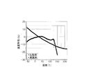
図1は、本発明の実施例及び比較例によるAC電界に対する誘電率の変化を示すグラフである。 FIG. 1 is a graph showing changes in dielectric constant with respect to an AC electric field according to examples and comparative examples of the present invention.
図1は、比較例である、強誘電体BaTiO3材料を適用したX7R(−55℃〜125℃)特性の積層セラミックキャパシタの試験片と、本発明の実施例である、誘電率130の常誘電体(Ca1−xSrx)(Zr1−yTiy)O3を適用した積層セラミックキャパシタの試験片のAC電界の大きさによる誘電率の変化を示す。 FIG. 1 shows a comparative example of a multilayer ceramic capacitor specimen having an X7R (−55 ° C. to 125 ° C.) characteristic to which a ferroelectric BaTiO 3 material is applied, and a dielectric constant of 130, which is an example of the present invention. It shows the change in dielectric constant by the dielectric (Ca 1-x Sr x) (Zr 1-y Ti y) the magnitude of AC electric field of the specimen of the multilayer ceramic capacitor according to the O 3.
図1を参照すると、BaTiO3材料を適用した比較例の場合に比べて、常誘電体(Ca1−xSrx)(Zr1−yTiy)O3を適用した実施例の場合は、AC電界の大きさによる誘電率の変化が殆どないことが確認できる。 Referring to FIG. 1, in the case of the example in which the paraelectric (Ca 1-x Sr x ) (Zr 1-y Ti y ) O 3 is applied, compared to the case of the comparative example in which the BaTiO 3 material is applied, It can be confirmed that there is almost no change in the dielectric constant due to the magnitude of the AC electric field.
図2は、本発明の実施例及び比較例によるDC電界に対する容量の変化を示すグラフである。 FIG. 2 is a graph showing a change in capacitance with respect to a DC electric field according to an example of the present invention and a comparative example.
図2は、比較例である、強誘電体BaTiO3材料を適用したX7R(−55℃〜125℃)特性の積層セラミックキャパシタの試験片と、本発明の高誘電率常誘電体(Ca1−xSrx)(Zr1−yTiy)O3を適用した積層セラミックキャパシタの試験片のDC電界の大きさによる容量の変化を示す。 FIG. 2 shows an X7R (−55 ° C. to 125 ° C.) characteristic multilayer ceramic capacitor test piece to which a ferroelectric BaTiO 3 material is applied as a comparative example, and the high dielectric constant paraelectric material (Ca 1− x Sr x) shows a change in capacitance due to (Zr 1-y Ti y) magnitude of the DC electric field of the specimen of the multilayer ceramic capacitor according to the O 3.
図2を参照すると、BaTiO3材料を適用した比較例の場合に比べて、常誘電体(Ca1−xSrx)(Zr1−yTiy)O3を適用した実施例の場合は、DC電界の大きさによる誘電率の変化が殆どなく容量の変化がないことが確認できる。 Referring to FIG. 2, in the case of the example in which the paraelectric (Ca 1−x Sr x ) (Zr 1−y Ti y ) O 3 is applied, compared to the case of the comparative example in which the BaTiO 3 material is applied, It can be confirmed that there is almost no change in the dielectric constant due to the magnitude of the DC electric field and there is no change in the capacitance.
図3は、本発明の実施例及び比較例による温度に対する誘電率の変化を示すグラフである。 FIG. 3 is a graph showing changes in dielectric constant with respect to temperature according to examples and comparative examples of the present invention.
図3は、比較例である、強誘電体BaTiO3材料を適用したX7R(−55℃〜125℃)特性の積層セラミックキャパシタの試験片と、本発明の高誘電率常誘電体(Ca1−xSrx)(Zr1−yTiy)O3を適用した積層セラミックキャパシタの試験片の温度による誘電率の変化を示す。 FIG. 3 shows an X7R (−55 ° C. to 125 ° C.) characteristic multilayer ceramic capacitor test piece to which a ferroelectric BaTiO 3 material is applied as a comparative example, and the high dielectric constant paraelectric material (Ca 1− It shows the x Sr x) (Zr 1- y Ti y) change in dielectric constant with temperature of the test piece of a laminated ceramic capacitor according to the O 3.
図3を参照すると、BaTiO3材料を適用した比較例の場合に比べて、常誘電体(Ca1−xSrx)(Zr1−yTiy)O3を適用した実施例の場合は、150℃以上の静電容量変化率(temperature coefficient of capacitance、TCC)に優れ、X8R以上(−55℃〜175℃)の特性を具現することができることが分かる。 Referring to FIG. 3, in the case of the example in which the paraelectric (Ca 1-x Sr x ) (Zr 1-y Ti y ) O 3 is applied, compared to the case of the comparative example in which the BaTiO 3 material is applied, It can be seen that it has an excellent capacitance change capacity (TCC) of 150 ° C. or higher, and can realize characteristics of X8R or higher (−55 ° C. to 175 ° C.).
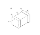
図4は、本発明の一実施形態による積層セラミックキャパシタ100を示す概略的な斜視図であり、図5は、図4のA−A'線に沿う積層セラミックキャパシタ100を示す概略的な断面図である。
4 is a schematic perspective view illustrating a multilayer
図4及び図5を参照すると、本発明の他の実施例による積層セラミックキャパシタ100は、誘電体層111と第1及び第2の内部電極121、122が交互に積層されたセラミック本体110を有する。セラミック本体110の両端部には、セラミック本体110の内部に交互に配置された第1及び第2の内部電極121、122とそれぞれ導通する第1及び第2の外部電極131、132が形成されている。
4 and 5, a multilayer
セラミック本体110は、その形状に特に制限はないが、一般に直方体状であればよい。また、その寸法にも特に制限はなく、用途に応じて適切に変更可能であり、例えば、(0.6〜5.6mm)×(0.3〜5.0mm)×(0.3〜1.9mm)であればよい。
The shape of the
誘電体層111の厚さはキャパシタの容量設計に合わせて任意に変更可能であり、本発明の一実施例において焼成後の誘電体層の厚さは1層当たり好ましくは0.1μm以上である。
The thickness of the
薄すぎる厚さの誘電体層は一層内に存在する結晶粒数が少なく、信頼性に悪影響を及ぼすため、誘電体層の厚さは0.1μm以上であればよい。 Since the dielectric layer having a thickness that is too thin has a small number of crystal grains in one layer and adversely affects reliability, the thickness of the dielectric layer may be 0.1 μm or more.
第1及び第2の内部電極121、122は、各端面がセラミック本体110の反対側の両端部の表面に交互に露出するように積層されている。
The first and second
上記第1及び第2の外部電極131、132は、セラミック本体110の両端部に形成され、交互に配置された第1及び第2の内部電極121、122の露出端面に電気的に連結されてキャパシタ回路を構成する。
The first and second
上記第1及び第2の内部電極121、122に含有される導電性材料は、特に限定されないが、本発明の一実施形態による誘電体層の構成材料が常誘電体材料を有することから貴金属を通常用いることができ、本発明の一実施形態ではニッケル(Ni)内部電極を用いることもできる。
The conductive material contained in the first and second
上記導電性材料として用いる貴金属は銀(Ag)又はパラジウム(Pd)合金であればよい。 The noble metal used as the conductive material may be a silver (Ag) or palladium (Pd) alloy.
上記第1及び第2の内部電極121、122の厚さは、用途などに応じて適切に決定可能であり、特に制限されないが、例えば、0.1〜5μm又は0.1〜2.5μmであればよい。
The thicknesses of the first and second
上記第1及び第2の外部電極131、132に含有される導電性材料としては、特に限定されないが、ニッケル(Ni)、銅(Cu)、又はこれらの合金を用いることができる。
The conductive material contained in the first and second
上記第1及び第2の外部電極131、132の厚さは、用途などに応じて適切に決定可能であり、特に制限されないが、例えば、10〜50μmであればよい。
The thicknesses of the first and second
上記セラミック本体110を構成する誘電体層111は、本発明の一実施形態による誘電体磁器組成物を含むことができる。
The
本発明の一実施形態による誘電体磁器組成物は、(Ca1−xSrx)(Zr1−yTiy)O3で表示される母材粉末(上記xの範囲は0≦x≦1.0、yの範囲は0.3≦y≦0.8)を含むことができる。 The dielectric ceramic composition according to an embodiment of the present invention includes a base material powder represented by (Ca 1−x Sr x ) (Zr 1−y Ti y ) O 3 (the range of x is 0 ≦ x ≦ 1). The range of 0.0, y can include 0.3 ≦ y ≦ 0.8).
上記誘電体磁器組成物は、上述した本発明の一実施形態による誘電体磁器組成物の特徴と同一であるため、ここではその具体的な説明を省略する。 Since the dielectric ceramic composition has the same characteristics as those of the dielectric ceramic composition according to the embodiment of the present invention described above, the detailed description thereof is omitted here.
以下、実施例及び比較例を挙げて本発明をより詳細に説明するが、これは、発明の具体的な理解のためのものであり、本発明の範囲を限定するものではない。 EXAMPLES Hereinafter, although an Example and a comparative example are given and this invention is demonstrated in detail, this is for the specific understanding of invention, and does not limit the scope of the present invention.
母材粉末である主成分(Ca1−xSrx)(Zr1−yTiy)O3粉末は、次のように固相法を適用して製造された。 The main component (Ca 1-x Sr x ) (Zr 1-y Ti y ) O 3 powder as the base material powder was produced by applying the solid phase method as follows.
出発原料はCaCO3、SrCO3、ZrO2、TiO2である。 Starting materials are CaCO 3 , SrCO 3 , ZrO 2 , TiO 2 .
まず、これらの粉末を設計比率の通りに秤量してボールミルで混合し、800〜900℃の範囲にか焼して、平均粒子サイズ300nmの(Ca1−xSrx)(Zr1−yTiy)O3粉末を準備した。 First, these powders are weighed according to the design ratio, mixed by a ball mill, calcined in the range of 800 to 900 ° C., and (Ca 1−x Sr x ) (Zr 1−y Ti) having an average particle size of 300 nm. y ) O 3 powder was prepared.
下記表1と表2の各実験例に明示された組成比に合わせて主成分(Ca1−xSrx)(Zr1−yTiy)O3粉末(母材粉末)とそれぞれの副成分MnO2、Y2O3、SiO2を秤量し、主成分と副成分が含まれた原料粉末に、ジルコニアボールを混合/分散メディアとして用いてエタノール/トルエンと分散剤及びバインダーを混合した後、20時間ボールミリングした。 The main component (Ca 1-x Sr x ) (Zr 1-y Ti y ) O 3 powder (base material powder) and the subcomponents thereof according to the composition ratio specified in each experimental example in Table 1 and Table 2 below MnO 2 , Y 2 O 3 , SiO 2 are weighed, and after mixing ethanol / toluene, a dispersing agent and a binder using zirconia balls as a mixing / dispersing medium to a raw material powder containing a main component and subcomponents, Ball milled for 20 hours.
製造されたスラリーをドクターブレード方式のコーターを用いて5.0μmと10〜13μmの厚さにして成形シートを製造した。 The produced slurry was made to have a thickness of 5.0 μm and 10 to 13 μm using a doctor blade type coater to produce a molded sheet.
成形シートにNi内部電極印刷をした。 The Ni internal electrode was printed on the molded sheet.
カバー用シート(10〜13μmの厚さ)を25層ずつ積層して上カバー及び下カバーを製作し、内部電極の印刷された21層の活性シートを加圧し積層してバー(bar)を製作した。 25 sheets of cover sheets (thickness of 10-13 μm) are laminated to produce upper and lower covers, and 21 layers of active sheets printed with internal electrodes are pressed and laminated to produce a bar. did.
この圧着バーを、切断機を用いて3216(長さ×幅×厚さ:3.2mm×1.6mm×1.6mm)サイズのチップに切断した。 This crimp bar was cut into 3216 (length × width × thickness: 3.2 mm × 1.6 mm × 1.6 mm) size chips using a cutting machine.
製作が完了したチップをか焼し、還元雰囲気(1%H2/99%N2、H2O/H2/N2雰囲気)で1230〜1270℃の温度で2時間焼成した後、1000℃で窒素(N2)雰囲気で再酸化を3時間行って熱処理した。 The chip after fabrication is calcined, fired at a temperature of 1230 to 1270 ° C. for 2 hours in a reducing atmosphere (1% H 2 /99% N 2 , H 2 O / H 2 / N 2 atmosphere), and then 1000 ° C. Then, re-oxidation was performed in a nitrogen (N 2 ) atmosphere for 3 hours to perform heat treatment.
焼成されたチップに対して銅(Cu)ペーストを用いてターミネーション工程及び電極焼成を施して外部電極を形成した。 The fired chip was subjected to a termination process and electrode firing using a copper (Cu) paste to form an external electrode.
上記のように完成されたプロトタイプの積層セラミックキャパシタ(Proto−type MLCC)の試験片に対して容量、DF、絶縁抵抗、TCC及び高温150℃での電圧step増加による抵抗劣化挙動などを評価した。 The prototype multilayer ceramic capacitor (Proto-type MLCC) completed as described above was evaluated for its capacity, DF, insulation resistance, TCC, and resistance degradation behavior due to an increase in voltage step at a high temperature of 150 ° C.
積層セラミックキャパシタ(MLCC)チップの常温静電容量及び誘電損失は、LCR−meterを用いて1kHz、AC0.5V/μmの条件で容量を測定した。 The capacitance at room temperature and the dielectric loss of the multilayer ceramic capacitor (MLCC) chip were measured under the conditions of 1 kHz, AC 0.5 V / μm using an LCR-meter.
静電容量と積層セラミックキャパシタ(MLCC)チップの誘電体の厚さ、内部電極の面積、積層数から積層セラミックキャパシタ(MLCC)チップの誘電率を計算した。 The dielectric constant of the multilayer ceramic capacitor (MLCC) chip was calculated from the capacitance, the dielectric thickness of the multilayer ceramic capacitor (MLCC) chip, the area of the internal electrode, and the number of stacked layers.
常温絶縁抵抗(IR)は、10個ずつのサンプルを取ってDC10V/μmを印加した状態で60秒経過した後に測定した。 The room temperature insulation resistance (IR) was measured after 60 seconds had elapsed with 10 samples taken and DC 10 V / μm applied.
温度による静電容量の変化は、−55℃から175℃の温度範囲で測定した。 The change in capacitance with temperature was measured in the temperature range of −55 ° C. to 175 ° C.
高温IR昇圧実験では、170℃で電圧を10V/μmずつ印加して電圧ステップを増加させながら抵抗劣化挙動を測定した。各段階の時間は10分であり、5秒間隔で抵抗値を測定した。 In the high-temperature IR boost experiment, the resistance degradation behavior was measured while increasing the voltage step by applying a voltage of 10 V / μm at 170 ° C. The time for each stage was 10 minutes, and the resistance value was measured at 5-second intervals.
高温IR昇圧実験から高温耐電圧を導出した。これは、焼成後に厚さ3.2μmの20層の誘電体層を有する3216サイズのチップに対して175℃で5V/μmのDC電圧を10分間印加し電圧ステップ(Voltage step)を継続的に増加させながら測定したときにIRが105Ω以上になる電圧を意味する。 The high temperature withstand voltage was derived from the high temperature IR boost experiment. This is because a DC voltage of 5 V / μm is applied to a 3216 size chip having 20 dielectric layers having a thickness of 3.2 μm after firing at 175 ° C. for 10 minutes, and a voltage step is continuously performed. It means a voltage at which IR becomes 10 5 Ω or more when measured while increasing.

上記表1を参照すると、実験例1〜10は、主成分(Ca1−xSrx)(Zr1−yTiy)O3粉末に対して第1の副成分MnO2及び第3の副成分SiO2の含量がそれぞれ0.5at%及び0.5at%であり、第1の主成分のSr含量x=0のときの、Ti含量yの変化例を示し、表2の1〜10は、これらの実験例によるproto−typeの積層セラミックキャパシタの特性を示す。 Referring to Table 1 above, Experimental Examples 1 to 10 are based on the first subcomponent MnO 2 and the third subcomponent with respect to the main component (Ca 1-x Sr x ) (Zr 1-y Ti y ) O 3 powder. Examples of changes in the Ti content y when the content of the component SiO 2 is 0.5 at% and 0.5 at%, respectively, and the Sr content x = 0 of the first main component, The characteristics of the proto-type multilayer ceramic capacitor according to these experimental examples are shown.
表1及び表2を参照すると、Ti含量yが増加するにつれて常温誘電率が増加し、且つ高温部175℃でのTCCであるTCC(175℃)が低下し、高温175℃での耐電圧特性が低くなることが分かる。 Referring to Table 1 and Table 2, as the Ti content y increases, the room temperature dielectric constant increases, and the TCC (175 ° C.), which is the TCC at the high temperature portion 175 ° C., decreases. Withstand voltage characteristics at the high temperature 175 ° C. It turns out that becomes low.
Ti含量yが0.3以上のときから90以上の誘電率が得られるが、0.9以上と過量の場合にはTCC(175℃)が±15%の範囲を外れるという問題が発生する。 A dielectric constant of 90 or more can be obtained when the Ti content y is 0.3 or more. However, when the Ti content is excessively 0.9 or more, there is a problem that TCC (175 ° C.) is out of the range of ± 15%.
Ti含量yが0.3≦y≦0.8の範囲で本発明の目標特性である90以上の誘電率、1000以上のRC値、X9R温度特性、及び50V/μm以上の高温(175℃)耐電圧の全ての特性を同時に具現することができるため、適正なy含量の範囲が0.3≦y≦0.8であることが分かる。 When the Ti content y is in the range of 0.3 ≦ y ≦ 0.8, the dielectric constant of 90 or more, the RC value of 1000 or more, the X9R temperature characteristic, and the high temperature (175 ° C.) of 50 V / μm or more which are the target characteristics Since all the characteristics of the withstand voltage can be realized at the same time, it can be seen that the range of the proper y content is 0.3 ≦ y ≦ 0.8.
表1の実験例11〜15は、(Ca1−xSrx)(Zr1−yTiy)O3粉末に対して第1の副成分MnO2及び第3の副成分SiO2の含量がそれぞれ0.5at%及び0.5at%であり、第1の主成分のTi含量y=0.6のときの、Sr含量xの変化例を示し、表2の11〜15は、これらの実験例によるproto−typeの積層セラミックキャパシタの特性を示す。 In Experimental Examples 11 to 15 in Table 1, the contents of the first subcomponent MnO 2 and the third subcomponent SiO 2 with respect to (Ca 1-x Sr x ) (Zr 1-y Ti y ) O 3 powder Examples of changes in the Sr content x when the Ti content of the first main component is y = 0.6 are 0.5 at% and 0.5 at%, respectively. The characteristic of the proto-type multilayer ceramic capacitor by an example is shown.
Sr含量の全範囲0≦x≦1.0において誘電率、DF、常温RC値、TCC(175℃)、及び高温(175℃)耐電圧の特性が同じような水準で具現され、本発明の目標特性を満たすことが分かる。
The characteristics of dielectric constant, DF, room temperature RC value, TCC (175 ° C.), and high temperature (175 ° C.) withstand voltage are embodied at the same level in the entire range of
したがって、適正なSr含量のx範囲が0≦x≦1.0を満たすことが分かる。 Therefore, it can be seen that the appropriate x range of the Sr content satisfies 0 ≦ x ≦ 1.0.
表3の実験例16〜22は、主成分(Ca1−xSrx)(Zr1−yTiy)O3粉末においてx=0.4、y=0.6であり、第3の副成分SiO2の含量が0.5のときの、第1の副成分Mnの含量の変化による実験例を示し、表4の16〜22は、これらの実験例によるproto−typeの積層セラミックキャパシタの特性を示す。 In Experimental Examples 16 to 22 in Table 3, x = 0.4 and y = 0.6 in the main component (Ca 1-x Sr x ) (Zr 1-y Ti y ) O 3 powder, Experimental examples by changing the content of the first subcomponent Mn when the content of the component SiO 2 is 0.5 are shown. Tables 16 to 22 in Table 4 show the prototype type multilayer ceramic capacitors of these experimental examples. Show the characteristics.
Mnの含量が0.1at%と少ない場合(実験例16)は、高温(175℃)耐電圧が35V/μmと低くなるという問題があり、Mnの含量が0.2at%以上増加する場合は、高温(175℃)耐電圧が50V/μm以上に上昇(実験例17〜21)し、Mnの含量が5at%と過量の場合(実験例22)は、二次相などが生成されて高温(175℃)耐電圧が50V/μm未満と再び低くなるという問題が発生する。 When the content of Mn is as low as 0.1 at% (Experimental Example 16), there is a problem that the withstand voltage at high temperature (175 ° C.) is as low as 35 V / μm, and when the content of Mn is increased by 0.2 at% or more. When the withstand voltage is increased to 50 V / μm or more (Experimental Examples 17 to 21) and the Mn content is excessively 5 at% (Experimental Example 22), secondary phases are generated and the temperature is high. (175 ° C.) The problem arises that the withstand voltage is lowered again to less than 50 V / μm.
したがって、第1の副成分Mnの適正含量は0.2〜4at%であることが分かる。 Therefore, it can be seen that the appropriate content of the first subcomponent Mn is 0.2 to 4 at%.
表3の実験例27〜30は、主成分(Ca1−xSrx)(Zr1−yTiy)O3粉末においてx=0.4、y=0.6であり、第1の副成分Mnの含量が2.0at%であり、第3の副成分SiO2の含量が0.5at%のときの、第2の副成分Y2O3の含量の変化による実験例を示し、表4の27〜30は、これらの実験例によるproto−typeの積層セラミックキャパシタの特性を示す。 In Experimental Examples 27 to 30 in Table 3, x = 0.4 and y = 0.6 in the main component (Ca 1-x Sr x ) (Zr 1-y Ti y ) O 3 powder, When the content of the component Mn is 2.0 at% and the content of the third subcomponent SiO 2 is 0.5 at%, an experimental example is shown according to a change in the content of the second subcomponent Y 2 O 3. Nos. 27 to 30 in FIG. 4 show the characteristics of the proto-type multilayer ceramic capacitors according to these experimental examples.
Yの含量が増加するにつれて高温(175℃)耐電圧が上昇してから再び減少し、at%を基準に6at%と過量の場合(実験例30)は、二次相などの生成によって高温(175℃)耐電圧が50V/μm未満と低くなるという問題がある。 As the Y content increases, the withstand voltage increases at a high temperature (175 ° C.) and then decreases again. In the case of an excess amount of 6 at% based on at% (Experimental Example 30), the high temperature ( 175 ° C.) There is a problem that the withstand voltage is as low as less than 50 V / μm.
したがって、第2の副成分Yの適正含量は、at%を基準に0at%より大きく4at%以下であることが分かる。 Therefore, it can be seen that the appropriate content of the second subcomponent Y is greater than 0 at% and not greater than 4 at% with reference to at%.
表3の実験例31〜34は、主成分(Ca1−xSrx)(Zr1−yTiy)O3粉末においてx=0.4、y=0.6であり、第1の副成分Mnの含量が2.0at%であり、第3の副成分SiO2の含量が0.5at%であり、且つ第2の副成分Y2O3をDy2O3に変更するか又はY2O3とDy2O3を共に添加したときの実験例を示し、表4の31〜34は、これらの実験例によるproto−typeの積層セラミックキャパシタの特性を示す。 In Experimental Examples 31 to 34 in Table 3, x = 0.4 and y = 0.6 in the main component (Ca 1-x Sr x ) (Zr 1-y Ti y ) O 3 powder, The content of the component Mn is 2.0 at%, the content of the third subcomponent SiO 2 is 0.5 at%, and the second subcomponent Y 2 O 3 is changed to Dy 2 O 3 or Y Experimental examples when both 2 O 3 and Dy 2 O 3 are added are shown, and 31 to 34 in Table 4 show the characteristics of the proto-type multilayer ceramic capacitors according to these experimental examples.
at%を基準に、第2の副成分全体の含量が同一の場合においてY又はDy単独の場合又はYとDyが共に添加された場合の特性はほぼ同一であり、第2の副成分Dyの含量が6at%と過量の場合(実験例33)は同様に高温(175℃)耐電圧が50V/μm未満と低くなることが分かる。 In the case where the content of the entire second subcomponent is the same based on at%, the characteristics of Y or Dy alone or when Y and Dy are added together are almost the same. It can be seen that when the content is excessively 6 at% (Experimental Example 33), the withstand voltage is similarly lowered to less than 50 V / μm at a high temperature (175 ° C.).
表3の実験例35〜39は、主成分(Ca1−xSrx)(Zr1−yTiy)O3粉末においてx=0.4、y=0.6であり、第1の副成分Mnの含量が2.0、第2の副成分Y2O3がat%で2.0at%のときの、第3の副成分SiO2の含量の変化による実験例を示し、表4の35〜39は、これらの実験例によるproto−typeの積層セラミックキャパシタの特性を示す。 In Experimental Examples 35 to 39 in Table 3, x = 0.4 and y = 0.6 in the main component (Ca 1-x Sr x ) (Zr 1-y Ti y ) O 3 powder, When the content of the component Mn is 2.0 and the second subcomponent Y 2 O 3 is at% and 2.0 at%, an experimental example by changing the content of the third subcomponent SiO 2 is shown. 35 to 39 show the characteristics of the proto-type multilayer ceramic capacitors according to these experimental examples.
SiO2含量が0.25at%と非常に小さい場合(実験例35)は、誘電体層の緻密度が低く、高温(175℃)耐電圧が50V/μm未満と低くなるという問題がある。 When the SiO 2 content is as very small as 0.25 at% (Experimental Example 35), there is a problem that the density of the dielectric layer is low, and the high-temperature (175 ° C.) withstand voltage is as low as less than 50 V / μm.
SiO2含量が増加するにつれて高温(175℃)耐電圧が増加してから減少することが確認できる。SiO2含量が5at%と過量の場合は、二次相の生成などによって同様に高温(175℃)耐電圧が50V/μm未満と低くなるという問題があることが分かる。 It can be confirmed that the withstand voltage increases at a high temperature (175 ° C.) as the SiO 2 content increases and then decreases. When the SiO 2 content is excessive at 5 at%, it can be seen that there is a problem that the high-temperature (175 ° C.) withstand voltage is similarly reduced to less than 50 V / μm due to the formation of the secondary phase.
SiO2含量が0.5〜4.0at%の範囲で本発明の全ての目標特性を同時に具現することができるため、第3の副成分SiO2の適正含量は0.5〜4.0at%であることが分かる。 Since all the target characteristics of the present invention can be realized at the same time when the SiO 2 content is in the range of 0.5 to 4.0 at%, the appropriate content of the third subcomponent SiO 2 is 0.5 to 4.0 at%. It turns out that it is.
以上、本発明の実施形態について詳細に説明したが、本発明の権利範囲はこれに限定されず、特許請求の範囲に記載された本発明の技術的思想から外れない範囲内で多様な修正及び変形が可能であるということは、当技術分野の通常の知識を有する者には明らかである。 Although the embodiment of the present invention has been described in detail above, the scope of the right of the present invention is not limited to this, and various modifications and modifications can be made without departing from the technical idea of the present invention described in the claims. It will be apparent to those skilled in the art that variations are possible.
100 積層セラミックキャパシタ
110 セラミック本体
111 誘電体層
121、122 第1及び第2の内部電極
131、132 第1及び第2の外部電極
DESCRIPTION OF
Claims (10)
前記誘電体層は、(Ca1−xSrx)(Zr1−yTiy)O3で表示される母材粉末(xの範囲は0≦x≦1.0、yの範囲は0.3≦y≦0.8)を含む誘電体磁器組成物を含む、積層セラミックキャパシタ。 Including a ceramic body in which dielectric layers and first and second internal electrodes are alternately stacked;
The dielectric layer is made of a base material powder represented by (Ca 1−x Sr x ) (Zr 1−y Ti y ) O 3 (the range of x is 0 ≦ x ≦ 1.0, and the range of y is 0. A multilayer ceramic capacitor comprising a dielectric ceramic composition comprising 3 ≦ y ≦ 0.8).
Applications Claiming Priority (2)
| Application Number | Priority Date | Filing Date | Title |
|---|---|---|---|
| KR10-2015-0095992 | 2015-07-06 | ||
| KR1020150095992A KR20170005646A (en) | 2015-07-06 | 2015-07-06 | Dielectric ceramic composition and multilayer ceramic capacitor comprising the same |
Publications (2)
| Publication Number | Publication Date |
|---|---|
| JP2017014094A true JP2017014094A (en) | 2017-01-19 |
| JP6870803B2 JP6870803B2 (en) | 2021-05-12 |
Family
ID=57730515
Family Applications (1)
| Application Number | Title | Priority Date | Filing Date |
|---|---|---|---|
| JP2016069162A Active JP6870803B2 (en) | 2015-07-06 | 2016-03-30 | Dielectric porcelain composition and multilayer ceramic capacitors containing it |
Country Status (3)
| Country | Link |
|---|---|
| US (1) | US20170008806A1 (en) |
| JP (1) | JP6870803B2 (en) |
| KR (1) | KR20170005646A (en) |
Cited By (2)
| Publication number | Priority date | Publication date | Assignee | Title |
|---|---|---|---|---|
| JP2020023423A (en) * | 2018-08-06 | 2020-02-13 | サムソン エレクトロ−メカニックス カンパニーリミテッド. | Dielectric composition and electronic component using the same |
| US20220076892A1 (en) * | 2020-09-10 | 2022-03-10 | Kemet Electronics Corporation | Resonant Multilayer Ceramic Capacitors |
Families Citing this family (2)
| Publication number | Priority date | Publication date | Assignee | Title |
|---|---|---|---|---|
| KR102538902B1 (en) * | 2016-02-24 | 2023-06-01 | 삼성전기주식회사 | Electronic component and manufactiuring method of the same |
| KR102409109B1 (en) * | 2018-08-06 | 2022-06-15 | 삼성전기주식회사 | Dielectric composition and electronic component using the same |
Citations (5)
| Publication number | Priority date | Publication date | Assignee | Title |
|---|---|---|---|---|
| JP2002274938A (en) * | 2000-02-09 | 2002-09-25 | Tdk Corp | Dielectric ceramic composition, electronic part and method for manufacturing the part |
| JP2004075452A (en) * | 2002-08-16 | 2004-03-11 | Taiyo Yuden Co Ltd | Dielectric ceramic composition and ceramic capacitor |
| JP4461679B2 (en) * | 2000-06-29 | 2010-05-12 | Tdk株式会社 | Dielectric porcelain composition and electronic component |
| WO2012046554A1 (en) * | 2010-10-04 | 2012-04-12 | 株式会社村田製作所 | Laminated ceramic capacitor and method for manufacturing same |
| JP2012156386A (en) * | 2011-01-27 | 2012-08-16 | Taiyo Yuden Co Ltd | Variable capacitor |
-
2015
- 2015-07-06 KR KR1020150095992A patent/KR20170005646A/en not_active IP Right Cessation
-
2016
- 2016-02-18 US US15/047,263 patent/US20170008806A1/en not_active Abandoned
- 2016-03-30 JP JP2016069162A patent/JP6870803B2/en active Active
Patent Citations (5)
| Publication number | Priority date | Publication date | Assignee | Title |
|---|---|---|---|---|
| JP2002274938A (en) * | 2000-02-09 | 2002-09-25 | Tdk Corp | Dielectric ceramic composition, electronic part and method for manufacturing the part |
| JP4461679B2 (en) * | 2000-06-29 | 2010-05-12 | Tdk株式会社 | Dielectric porcelain composition and electronic component |
| JP2004075452A (en) * | 2002-08-16 | 2004-03-11 | Taiyo Yuden Co Ltd | Dielectric ceramic composition and ceramic capacitor |
| WO2012046554A1 (en) * | 2010-10-04 | 2012-04-12 | 株式会社村田製作所 | Laminated ceramic capacitor and method for manufacturing same |
| JP2012156386A (en) * | 2011-01-27 | 2012-08-16 | Taiyo Yuden Co Ltd | Variable capacitor |
Cited By (5)
| Publication number | Priority date | Publication date | Assignee | Title |
|---|---|---|---|---|
| JP2020023423A (en) * | 2018-08-06 | 2020-02-13 | サムソン エレクトロ−メカニックス カンパニーリミテッド. | Dielectric composition and electronic component using the same |
| JP7311256B2 (en) | 2018-08-06 | 2023-07-19 | サムソン エレクトロ-メカニックス カンパニーリミテッド. | Dielectric composition and electronic component using the same |
| US20220076892A1 (en) * | 2020-09-10 | 2022-03-10 | Kemet Electronics Corporation | Resonant Multilayer Ceramic Capacitors |
| US11621126B2 (en) * | 2020-09-10 | 2023-04-04 | Kemet Electronics Corporation | Resonant multilayer ceramic capacitors |
| US20230187134A1 (en) * | 2020-09-10 | 2023-06-15 | Kemet Electronics Corporation | Resonant Multilayer Ceramic Capacitors |
Also Published As
| Publication number | Publication date |
|---|---|
| JP6870803B2 (en) | 2021-05-12 |
| KR20170005646A (en) | 2017-01-16 |
| US20170008806A1 (en) | 2017-01-12 |
Similar Documents
| Publication | Publication Date | Title |
|---|---|---|
| JP7338825B2 (en) | Dielectric porcelain composition, multi-layer ceramic capacitor containing the same, and method for manufacturing multi-layer ceramic capacitor | |
| JP6957802B2 (en) | Dielectric porcelain compositions, dielectric materials and multilayer ceramic capacitors containing them | |
| JP6332648B2 (en) | Dielectric ceramic composition and multilayer ceramic capacitor including the same | |
| JP6915222B2 (en) | Dielectric composition and multilayer ceramic capacitors containing it | |
| JP7283019B2 (en) | Dielectric porcelain composition, multi-layer ceramic capacitor containing the same, and method for manufacturing multi-layer ceramic capacitor | |
| JP6852845B2 (en) | Dielectric porcelain composition and multilayer ceramic capacitors containing it | |
| JP2016108217A (en) | Dielectric ceramic composition, and multilayer ceramic capacitor including the same | |
| JP2016113355A (en) | Dielectric ceramic composition, dielectric material and multilayer ceramic capacitor including the same | |
| JP2013079183A (en) | Dielectric composition and ceramic electronic component comprising the same | |
| JP6523930B2 (en) | Dielectric ceramic composition and multilayer ceramic capacitor including the same | |
| JP2013079182A (en) | Dielectric composition and ceramic electronic component comprising the same | |
| KR102097326B1 (en) | Dielectric ceramic composition and multilayer ceramic capacitor comprising the same | |
| JP2020055745A (en) | Dielectric ceramic composition, dielectric material and multilayer ceramic capacitor containing the same | |
| JP6870803B2 (en) | Dielectric porcelain composition and multilayer ceramic capacitors containing it | |
| US9458063B2 (en) | Dielectric ceramic composition and multilayer ceramic capacitor including the same | |
| JP2018133501A (en) | Multilayer ceramic capacitor and method for manufacturing the same | |
| JP6841479B2 (en) | Dielectric composition and multilayer ceramic capacitors containing it | |
| JP6760689B2 (en) | Dielectric porcelain compositions, dielectric materials, and multilayer ceramic capacitors containing them | |
| US20160221878A1 (en) | Dielectric composition and multilayer ceramic capacitor containing the same | |
| JP6841480B2 (en) | Dielectric composition and laminated electronic components containing it | |
| KR102184560B1 (en) | Dielectric ceramic composition and multilayer ceramic capacitor comprising the same | |
| KR102262901B1 (en) | Dielectric ceramic composition and multi-layer ceramic electronic component using the same | |
| KR20170017285A (en) | Dielectric ceramic composition and multilayer ceramic capacitor comprising the same |
Legal Events
| Date | Code | Title | Description |
|---|---|---|---|
| A621 | Written request for application examination |
Free format text: JAPANESE INTERMEDIATE CODE: A621 Effective date: 20190118 |
|
| A131 | Notification of reasons for refusal |
Free format text: JAPANESE INTERMEDIATE CODE: A131 Effective date: 20191119 |
|
| A521 | Request for written amendment filed |
Free format text: JAPANESE INTERMEDIATE CODE: A523 Effective date: 20200214 |
|
| A131 | Notification of reasons for refusal |
Free format text: JAPANESE INTERMEDIATE CODE: A131 Effective date: 20200331 |
|
| A521 | Request for written amendment filed |
Free format text: JAPANESE INTERMEDIATE CODE: A523 Effective date: 20200623 |
|
| A131 | Notification of reasons for refusal |
Free format text: JAPANESE INTERMEDIATE CODE: A131 Effective date: 20200714 |
|
| A521 | Request for written amendment filed |
Free format text: JAPANESE INTERMEDIATE CODE: A523 Effective date: 20201009 |
|
| TRDD | Decision of grant or rejection written | ||
| A01 | Written decision to grant a patent or to grant a registration (utility model) |
Free format text: JAPANESE INTERMEDIATE CODE: A01 Effective date: 20210316 |
|
| A61 | First payment of annual fees (during grant procedure) |
Free format text: JAPANESE INTERMEDIATE CODE: A61 Effective date: 20210331 |
|
| R150 | Certificate of patent or registration of utility model |
Ref document number: 6870803 Country of ref document: JP Free format text: JAPANESE INTERMEDIATE CODE: R150 |
|
| R250 | Receipt of annual fees |
Free format text: JAPANESE INTERMEDIATE CODE: R250 |