JP2017013946A - Article conveyance facility - Google Patents
Article conveyance facility Download PDFInfo
- Publication number
- JP2017013946A JP2017013946A JP2015131608A JP2015131608A JP2017013946A JP 2017013946 A JP2017013946 A JP 2017013946A JP 2015131608 A JP2015131608 A JP 2015131608A JP 2015131608 A JP2015131608 A JP 2015131608A JP 2017013946 A JP2017013946 A JP 2017013946A
- Authority
- JP
- Japan
- Prior art keywords
- guide portion
- power supply
- movement guide
- movement
- engagement
- Prior art date
- Legal status (The legal status is an assumption and is not a legal conclusion. Google has not performed a legal analysis and makes no representation as to the accuracy of the status listed.)
- Granted
Links
- 238000001514 detection method Methods 0.000 claims abstract description 29
- 238000009434 installation Methods 0.000 claims description 26
- 230000005856 abnormality Effects 0.000 claims description 19
- 238000003780 insertion Methods 0.000 claims description 14
- 230000037431 insertion Effects 0.000 claims description 14
- 238000006073 displacement reaction Methods 0.000 claims description 4
- 230000002159 abnormal effect Effects 0.000 claims 1
- 238000012544 monitoring process Methods 0.000 description 13
- 238000011144 upstream manufacturing Methods 0.000 description 13
- 238000010586 diagram Methods 0.000 description 3
- 230000005540 biological transmission Effects 0.000 description 1
- 210000000078 claw Anatomy 0.000 description 1
- 230000008878 coupling Effects 0.000 description 1
- 238000010168 coupling process Methods 0.000 description 1
- 238000005859 coupling reaction Methods 0.000 description 1
- 230000007423 decrease Effects 0.000 description 1
- 230000003247 decreasing effect Effects 0.000 description 1
- 230000005611 electricity Effects 0.000 description 1
- 230000013011 mating Effects 0.000 description 1
- 238000005192 partition Methods 0.000 description 1
- 230000000149 penetrating effect Effects 0.000 description 1
- 230000002265 prevention Effects 0.000 description 1
- 230000001105 regulatory effect Effects 0.000 description 1
- 230000000717 retained effect Effects 0.000 description 1
- 239000004065 semiconductor Substances 0.000 description 1
- 239000000758 substrate Substances 0.000 description 1
Images


Classifications
-
- B—PERFORMING OPERATIONS; TRANSPORTING
- B65—CONVEYING; PACKING; STORING; HANDLING THIN OR FILAMENTARY MATERIAL
- B65G—TRANSPORT OR STORAGE DEVICES, e.g. CONVEYORS FOR LOADING OR TIPPING, SHOP CONVEYOR SYSTEMS OR PNEUMATIC TUBE CONVEYORS
- B65G35/00—Mechanical conveyors not otherwise provided for
-
- B—PERFORMING OPERATIONS; TRANSPORTING
- B61—RAILWAYS
- B61B—RAILWAY SYSTEMS; EQUIPMENT THEREFOR NOT OTHERWISE PROVIDED FOR
- B61B3/00—Elevated railway systems with suspended vehicles
- B61B3/02—Elevated railway systems with suspended vehicles with self-propelled vehicles
-
- H—ELECTRICITY
- H01—ELECTRIC ELEMENTS
- H01L—SEMICONDUCTOR DEVICES NOT COVERED BY CLASS H10
- H01L21/00—Processes or apparatus adapted for the manufacture or treatment of semiconductor or solid state devices or of parts thereof
- H01L21/67—Apparatus specially adapted for handling semiconductor or electric solid state devices during manufacture or treatment thereof; Apparatus specially adapted for handling wafers during manufacture or treatment of semiconductor or electric solid state devices or components ; Apparatus not specifically provided for elsewhere
- H01L21/677—Apparatus specially adapted for handling semiconductor or electric solid state devices during manufacture or treatment thereof; Apparatus specially adapted for handling wafers during manufacture or treatment of semiconductor or electric solid state devices or components ; Apparatus not specifically provided for elsewhere for conveying, e.g. between different workstations
- H01L21/67703—Apparatus specially adapted for handling semiconductor or electric solid state devices during manufacture or treatment thereof; Apparatus specially adapted for handling wafers during manufacture or treatment of semiconductor or electric solid state devices or components ; Apparatus not specifically provided for elsewhere for conveying, e.g. between different workstations between different workstations
- H01L21/67724—Apparatus specially adapted for handling semiconductor or electric solid state devices during manufacture or treatment thereof; Apparatus specially adapted for handling wafers during manufacture or treatment of semiconductor or electric solid state devices or components ; Apparatus not specifically provided for elsewhere for conveying, e.g. between different workstations between different workstations by means of a cart or a vehicule
-
- B—PERFORMING OPERATIONS; TRANSPORTING
- B63—SHIPS OR OTHER WATERBORNE VESSELS; RELATED EQUIPMENT
- B63B—SHIPS OR OTHER WATERBORNE VESSELS; EQUIPMENT FOR SHIPPING
- B63B13/00—Conduits for emptying or ballasting; Self-bailing equipment; Scuppers
-
- B—PERFORMING OPERATIONS; TRANSPORTING
- B65—CONVEYING; PACKING; STORING; HANDLING THIN OR FILAMENTARY MATERIAL
- B65G—TRANSPORT OR STORAGE DEVICES, e.g. CONVEYORS FOR LOADING OR TIPPING, SHOP CONVEYOR SYSTEMS OR PNEUMATIC TUBE CONVEYORS
- B65G43/00—Control devices, e.g. for safety, warning or fault-correcting
-
- B—PERFORMING OPERATIONS; TRANSPORTING
- B65—CONVEYING; PACKING; STORING; HANDLING THIN OR FILAMENTARY MATERIAL
- B65G—TRANSPORT OR STORAGE DEVICES, e.g. CONVEYORS FOR LOADING OR TIPPING, SHOP CONVEYOR SYSTEMS OR PNEUMATIC TUBE CONVEYORS
- B65G49/00—Conveying systems characterised by their application for specified purposes not otherwise provided for
- B65G49/05—Conveying systems characterised by their application for specified purposes not otherwise provided for for fragile or damageable materials or articles
- B65G49/06—Conveying systems characterised by their application for specified purposes not otherwise provided for for fragile or damageable materials or articles for fragile sheets, e.g. glass
- B65G49/061—Lifting, gripping, or carrying means, for one or more sheets forming independent means of transport, e.g. suction cups, transport frames
-
- H—ELECTRICITY
- H01—ELECTRIC ELEMENTS
- H01L—SEMICONDUCTOR DEVICES NOT COVERED BY CLASS H10
- H01L21/00—Processes or apparatus adapted for the manufacture or treatment of semiconductor or solid state devices or of parts thereof
- H01L21/67—Apparatus specially adapted for handling semiconductor or electric solid state devices during manufacture or treatment thereof; Apparatus specially adapted for handling wafers during manufacture or treatment of semiconductor or electric solid state devices or components ; Apparatus not specifically provided for elsewhere
- H01L21/677—Apparatus specially adapted for handling semiconductor or electric solid state devices during manufacture or treatment thereof; Apparatus specially adapted for handling wafers during manufacture or treatment of semiconductor or electric solid state devices or components ; Apparatus not specifically provided for elsewhere for conveying, e.g. between different workstations
- H01L21/67703—Apparatus specially adapted for handling semiconductor or electric solid state devices during manufacture or treatment thereof; Apparatus specially adapted for handling wafers during manufacture or treatment of semiconductor or electric solid state devices or components ; Apparatus not specifically provided for elsewhere for conveying, e.g. between different workstations between different workstations
- H01L21/67706—Mechanical details, e.g. roller, belt
-
- H—ELECTRICITY
- H01—ELECTRIC ELEMENTS
- H01L—SEMICONDUCTOR DEVICES NOT COVERED BY CLASS H10
- H01L21/00—Processes or apparatus adapted for the manufacture or treatment of semiconductor or solid state devices or of parts thereof
- H01L21/67—Apparatus specially adapted for handling semiconductor or electric solid state devices during manufacture or treatment thereof; Apparatus specially adapted for handling wafers during manufacture or treatment of semiconductor or electric solid state devices or components ; Apparatus not specifically provided for elsewhere
- H01L21/677—Apparatus specially adapted for handling semiconductor or electric solid state devices during manufacture or treatment thereof; Apparatus specially adapted for handling wafers during manufacture or treatment of semiconductor or electric solid state devices or components ; Apparatus not specifically provided for elsewhere for conveying, e.g. between different workstations
- H01L21/67703—Apparatus specially adapted for handling semiconductor or electric solid state devices during manufacture or treatment thereof; Apparatus specially adapted for handling wafers during manufacture or treatment of semiconductor or electric solid state devices or components ; Apparatus not specifically provided for elsewhere for conveying, e.g. between different workstations between different workstations
- H01L21/67709—Apparatus specially adapted for handling semiconductor or electric solid state devices during manufacture or treatment thereof; Apparatus specially adapted for handling wafers during manufacture or treatment of semiconductor or electric solid state devices or components ; Apparatus not specifically provided for elsewhere for conveying, e.g. between different workstations between different workstations using magnetic elements
-
- H—ELECTRICITY
- H01—ELECTRIC ELEMENTS
- H01L—SEMICONDUCTOR DEVICES NOT COVERED BY CLASS H10
- H01L21/00—Processes or apparatus adapted for the manufacture or treatment of semiconductor or solid state devices or of parts thereof
- H01L21/67—Apparatus specially adapted for handling semiconductor or electric solid state devices during manufacture or treatment thereof; Apparatus specially adapted for handling wafers during manufacture or treatment of semiconductor or electric solid state devices or components ; Apparatus not specifically provided for elsewhere
- H01L21/677—Apparatus specially adapted for handling semiconductor or electric solid state devices during manufacture or treatment thereof; Apparatus specially adapted for handling wafers during manufacture or treatment of semiconductor or electric solid state devices or components ; Apparatus not specifically provided for elsewhere for conveying, e.g. between different workstations
- H01L21/67763—Apparatus specially adapted for handling semiconductor or electric solid state devices during manufacture or treatment thereof; Apparatus specially adapted for handling wafers during manufacture or treatment of semiconductor or electric solid state devices or components ; Apparatus not specifically provided for elsewhere for conveying, e.g. between different workstations the wafers being stored in a carrier, involving loading and unloading
- H01L21/67772—Apparatus specially adapted for handling semiconductor or electric solid state devices during manufacture or treatment thereof; Apparatus specially adapted for handling wafers during manufacture or treatment of semiconductor or electric solid state devices or components ; Apparatus not specifically provided for elsewhere for conveying, e.g. between different workstations the wafers being stored in a carrier, involving loading and unloading involving removal of lid, door, cover
-
- B—PERFORMING OPERATIONS; TRANSPORTING
- B65—CONVEYING; PACKING; STORING; HANDLING THIN OR FILAMENTARY MATERIAL
- B65G—TRANSPORT OR STORAGE DEVICES, e.g. CONVEYORS FOR LOADING OR TIPPING, SHOP CONVEYOR SYSTEMS OR PNEUMATIC TUBE CONVEYORS
- B65G2201/00—Indexing codes relating to handling devices, e.g. conveyors, characterised by the type of product or load being conveyed or handled
- B65G2201/02—Articles
- B65G2201/0297—Wafer cassette
-
- B—PERFORMING OPERATIONS; TRANSPORTING
- B65—CONVEYING; PACKING; STORING; HANDLING THIN OR FILAMENTARY MATERIAL
- B65G—TRANSPORT OR STORAGE DEVICES, e.g. CONVEYORS FOR LOADING OR TIPPING, SHOP CONVEYOR SYSTEMS OR PNEUMATIC TUBE CONVEYORS
- B65G2207/00—Indexing codes relating to constructional details, configuration and additional features of a handling device, e.g. Conveyors
- B65G2207/40—Safety features of loads, equipment or persons
-
- E—FIXED CONSTRUCTIONS
- E01—CONSTRUCTION OF ROADS, RAILWAYS, OR BRIDGES
- E01B—PERMANENT WAY; PERMANENT-WAY TOOLS; MACHINES FOR MAKING RAILWAYS OF ALL KINDS
- E01B2202/00—Characteristics of moving parts of rail systems, e.g. switches, special frogs, tongues
- E01B2202/02—Nature of the movement
-
- E—FIXED CONSTRUCTIONS
- E01—CONSTRUCTION OF ROADS, RAILWAYS, OR BRIDGES
- E01B—PERMANENT WAY; PERMANENT-WAY TOOLS; MACHINES FOR MAKING RAILWAYS OF ALL KINDS
- E01B2202/00—Characteristics of moving parts of rail systems, e.g. switches, special frogs, tongues
- E01B2202/08—Locking devices or mechanisms for inhibiting movement
-
- Y—GENERAL TAGGING OF NEW TECHNOLOGICAL DEVELOPMENTS; GENERAL TAGGING OF CROSS-SECTIONAL TECHNOLOGIES SPANNING OVER SEVERAL SECTIONS OF THE IPC; TECHNICAL SUBJECTS COVERED BY FORMER USPC CROSS-REFERENCE ART COLLECTIONS [XRACs] AND DIGESTS
- Y02—TECHNOLOGIES OR APPLICATIONS FOR MITIGATION OR ADAPTATION AGAINST CLIMATE CHANGE
- Y02T—CLIMATE CHANGE MITIGATION TECHNOLOGIES RELATED TO TRANSPORTATION
- Y02T30/00—Transportation of goods or passengers via railways, e.g. energy recovery or reducing air resistance
Abstract
Description
本発明は、壁体に形成された開口を貫通する走行経路に沿って走行する物品搬送車と、前記物品搬送車を走行経路に沿って案内する案内レールと、前記壁体の壁面に沿う移動により前記開口を閉鎖する防火扉と、を備え、前記案内レールが、経路長手方向で前記防火扉が設置される扉設置箇所に位置する移動案内部分と、前記扉設置箇所に対して経路長手方向の両側に位置する固定案内部分と、を備え、前記移動案内部分が、前記扉設置箇所に位置して前記固定案内部分と連なる状態となる案内位置と、前記扉設置箇所から退避して前記防火扉の通過を許容する状態となる退避位置と、に変位自在に構成されていると共に、前記案内位置から前記退避位置への変位が前記移動案内部分の自重により行われる物品搬送設備に関する。 The present invention relates to an article transport vehicle that travels along a travel path that penetrates an opening formed in a wall, a guide rail that guides the article transport vehicle along the travel path, and a movement along a wall surface of the wall. A fire door that closes the opening, and the guide rail is located in a door installation location where the fire door is installed in the longitudinal direction of the route, and the longitudinal direction of the route with respect to the door installation location. Fixed guide portions located on both sides of the door, and the movement guide portion is located at the door installation location and connected to the fixed guide portion; and the fire prevention by retreating from the door installation location The present invention relates to an article transport facility that is configured to be freely displaceable to a retracted position that allows passage of a door and that is displaced from the guide position to the retracted position by its own weight.
かかる物品搬送設備の従来例が、特開平7−172570号公報(特許文献1)に記載されている。特許文献1の物品搬送設備では、案内レールの移動案内部分に保持装置(電磁石)を備え、その保持装置に電力を供給して操作力を発生させることで、この保持装置の操作力により移動案内部分を案内位置に保持するように構成されている。
そして、防火扉を閉じる場合は、保持装置に対する給電を停止させることで保持装置の操作力を消失させて保持装置による移動案内部分に対する保持を解除し、移動案内部分を自重により退避位置に移動させていた。このように、電磁石への給電を停止させることで移動案内部分を案内位置から退避位置に自重により移動するように構成することで、火災が発生して防火扉を閉じるときに停電が発生していた場合でも、案内レールの移動案内部分を退避位置に変位させるように構成されている。
A conventional example of such an article conveyance facility is described in Japanese Patent Laid-Open No. 7-172570 (Patent Document 1). In the article conveying facility of Patent Document 1, a holding device (electromagnet) is provided in the movement guide portion of the guide rail, and power is supplied to the holding device to generate an operating force, whereby the movement guide is generated by the operating force of the holding device. The part is configured to be held at the guide position.
When closing the fire door, the operation force of the holding device is lost by stopping the power supply to the holding device to release the holding of the moving guide portion by the holding device, and the moving guide portion is moved to the retracted position by its own weight. It was. In this way, by stopping the power supply to the electromagnet, the moving guide part is moved from the guide position to the retracted position by its own weight, so that a power failure occurs when a fire occurs and the fire door is closed. Even in such a case, the moving guide portion of the guide rail is configured to be displaced to the retracted position.
上記した従来の物品搬送設備では、保持装置の操作力により移動案内部分を支持して移動案内部分が自重により退避位置に移動することを防止している。このように、保持装置の操作力により移動案内部分が退避位置に移動しないように保持しており、保持装置に供給する電力は、案内位置に位置する移動案内部分を案内位置から自重により落ちないように保持できる操作力を発揮できるような電力が必要である。
そして、近年では、省電力化が求められており、保持装置に対して供給される電力を抑えながら案内レールの移動案内部分を案内位置に保持できる物品搬送設備が求められる。
In the conventional article transport facility described above, the movement guide portion is supported by the operating force of the holding device, and the movement guide portion is prevented from moving to the retreat position by its own weight. In this way, the movement guide portion is held so as not to move to the retracted position by the operating force of the holding device, and the power supplied to the holding device does not drop from the guide position due to its own weight. Thus, the electric power which can demonstrate the operation force which can be held is required.
In recent years, power saving has been demanded, and there is a demand for an article transport facility that can hold the movement guide portion of the guide rail at the guide position while suppressing the power supplied to the holding device.
そこで、保持装置に対して供給する電力を抑えながら案内レールの移動案内部分を案内位置に保持できる物品搬送設備が求められる。 Accordingly, there is a need for an article transport facility that can hold the movement guide portion of the guide rail at the guide position while suppressing the power supplied to the holding device.
本発明に係る物品搬送設備の特徴構成は、壁体に形成された開口を貫通する走行経路に沿って走行する物品搬送車と、前記物品搬送車を走行経路に沿って案内する案内レールと、前記壁体の壁面に沿う移動により前記開口を閉鎖する防火扉と、を備え、前記案内レールが、経路長手方向で前記防火扉が設置される扉設置箇所に位置する移動案内部分と、前記扉設置箇所に対して経路長手方向の両側に位置する固定案内部分と、を備え、前記移動案内部分が、前記扉設置箇所に位置して前記固定案内部分と連なる状態となる案内位置と、前記扉設置箇所から退避して前記防火扉の通過を許容する状態となる退避位置と、に変位自在に構成されていると共に、前記案内位置から前記退避位置への変位が前記移動案内部分の自重により行われる物品搬送設備において、
前記案内位置にある状態の前記移動案内部分と前記固定案内部分とに係合して前記移動案内部分を前記案内位置に保持する係合位置と、前記移動案内部分と前記固定案内部分との係合のうちの少なくとも一方の係合が解除される解除位置と、に前記移動案内部分が前記案内位置から自重により移動する方向に対して交差する方向に変位自在であって、前記係合位置にある状態で前記案内部分を下方から支持する係合体と、前記係合体を前記係合位置から前記解除位置に向けて付勢する付勢体と、給電部から供給される電力により操作力を発生させて当該操作力により前記付勢体の付勢力に抗して前記係合体を前記係合位置に保持する保持装置と、前記給電部の作動を制御する給電制御部と、火災を検出する火災検出装置と、が備えられ、前記給電制御部が、前記給電部の作動を制御して、前記火災検出装置から火災の発生を示す火災情報が出力されていない間は、前記給電部から前記保持装置に電力が給電される給電状態を維持し、前記火災検出装置から前記火災情報が出力されたことを条件に、前記給電部から前記保持装置に電力が供給されない給電停止状態に切り換える点にある。
The characteristic configuration of the article transport facility according to the present invention includes an article transport vehicle that travels along a travel route that penetrates an opening formed in a wall, a guide rail that guides the article transport vehicle along the travel route, A fire door that closes the opening by movement along the wall surface of the wall, and the guide rail is located at a door installation location where the fire door is installed in the longitudinal direction of the path, and the door Fixed guide portions located on both sides in the longitudinal direction of the path with respect to the installation location, and the guide position where the moving guide portion is located at the door installation location and is connected to the fixed guide portion, and the door It is configured to be freely displaceable to a retreat position where the fire door is allowed to retreat from the installation location, and the displacement from the guide position to the retreat position is performed by the weight of the moving guide portion. Goods In transmission equipment,
An engagement position that engages the movement guide portion and the fixed guide portion in the guide position to hold the movement guide portion at the guide position, and the relationship between the movement guide portion and the fixed guide portion. And a disengagement position where at least one of the engagements is disengaged, and a direction intersecting the direction in which the movement guide portion moves by its own weight from the guide position, and is displaceable to the engagement position. An operating force is generated by an engagement body that supports the guide portion from below in a certain state, an urging body that urges the engagement body from the engagement position toward the release position, and electric power supplied from the power supply unit. A holding device that holds the engaging body in the engagement position against the biasing force of the biasing body by the operation force, a power supply control unit that controls the operation of the power feeding unit, and a fire that detects a fire A detection device, comprising: A power supply state in which power is supplied from the power supply unit to the holding device while the power control unit controls the operation of the power supply unit and fire information indicating the occurrence of a fire is not output from the fire detection device And the power supply unit switches to a power supply stop state in which power is not supplied to the holding device on condition that the fire information is output from the fire detection device.
この特徴構成によれば、火災検出装置から火災情報が出力されていない間は、給電部から保持装置に電力が供給されることで、保持装置には付勢体の付勢力より大きい操作力が発生しており、その保持装置の操作力により係合体が係合位置に保持されて、係合位置に位置する係合体にて案内レールの移動案内部分は案内位置に支持される。
そして、火災検出装置から火災情報が出力されると、給電部から保持装置に給電が供給されなくなり、保持装置の操作力は消失するため、係合体は付勢体の付勢力により係合位置から解除位置に移動する。このように係合体が解除位置に移動することで、案内レールの移動案内部分は自重により移動して退避位置に変位する。
According to this characteristic configuration, while the fire information is not output from the fire detection device, power is supplied from the power feeding unit to the holding device, so that the holding device has an operation force larger than the biasing force of the biasing body. The engaging body is held at the engaging position by the operating force of the holding device, and the moving guide portion of the guide rail is supported at the guiding position by the engaging body positioned at the engaging position.
When the fire information is output from the fire detection device, power is not supplied from the power feeding unit to the holding device, and the operating force of the holding device disappears. Therefore, the engaging body is moved from the engaging position by the biasing force of the biasing body. Move to the release position. As the engaging body moves to the release position in this way, the movement guide portion of the guide rail moves due to its own weight and is displaced to the retracted position.
案内レールの移動案内部分は、係合位置に位置する係合体にて支持されている。そして、保持装置は、係合体を係合位置から退避位置に向けて付勢する付勢体の付勢力に抗して係合体を係合位置に保持している。つまり、保持装置の操作力は、付勢体の付勢力に抗して係合体を係合位置に保持する程度でよく、物品搬送車を案内する案内レールを直接に支持して案内位置に保持する場合に比べて小さな操作力でよいため、保持装置に供給する電力を抑えることができる。このように、保持装置に対して供給される電力を抑えながら案内レールの移動案内部分を案内位置に保持することができる。 The movement guide portion of the guide rail is supported by an engagement body located at the engagement position. The holding device holds the engagement body at the engagement position against the urging force of the urging body that urges the engagement body from the engagement position toward the retracted position. In other words, the operating force of the holding device may be such that the engaging body is held at the engaging position against the urging force of the urging body, and the guide rail for guiding the article transport vehicle is directly supported and held at the guiding position. Since a smaller operating force is sufficient as compared with the case of doing so, the power supplied to the holding device can be suppressed. In this manner, the movement guide portion of the guide rail can be held at the guide position while suppressing the power supplied to the holding device.
ここで、前記給電部が、主電源部と、蓄電部と、前記主電源部の異常を検出する主電源異常検出部と、を備え、前記給電部は、前記給電状態において前記主電源部又は前記蓄電部から前記保持装置に電力を供給するように構成され、かつ、前記給電状態において前記主電源異常検出部により前記主電源部に異常が検出されると、前記蓄電部の電力を前記保持装置に供給するように構成され、かつ、前記給電停止状態において、前記主電源部及び前記蓄電部のいずれからも前記保持装置に電力を供給しないように構成されていると好適である。 Here, the power supply unit includes a main power supply unit, a power storage unit, and a main power supply abnormality detection unit that detects an abnormality of the main power supply unit, and the power supply unit is the main power supply unit or The power storage unit is configured to supply power to the holding device, and the power of the power storage unit is held when an abnormality is detected in the main power supply unit by the main power supply abnormality detection unit in the power supply state. It is preferable that the apparatus is configured to supply power to the apparatus, and that the power is not supplied to the holding apparatus from either the main power supply unit or the power storage unit in the power supply stopped state.
この構成によれば、火災検出装置から火災情報が出力されていない間に、主電源部に故障が発生する等により主電源部から保持装置に電力を供給されないような主電源部に異常が生じた場合でも、このことが主電源異常検出部により検出されることで、蓄電部の電力が保持装置に供給されるようになる。このように、主電源部に異常が生じた場合でも、蓄電部から保持装置に電力を供給することで、移動案内部分を案内位置に保持することができる。従って、火災が発生していないときに、主電源部に異常が生じた場合でも案内レールの移動案内部分が自重により案内位置から移動することを防止できる。 According to this configuration, while the fire information is not output from the fire detection device, an abnormality occurs in the main power supply unit such that power is not supplied from the main power supply unit to the holding device due to a failure of the main power supply unit. Even in this case, when this is detected by the main power supply abnormality detection unit, the power of the power storage unit is supplied to the holding device. Thus, even when an abnormality occurs in the main power supply unit, the movement guide portion can be held at the guide position by supplying power from the power storage unit to the holding device. Therefore, even when an abnormality occurs in the main power supply unit when no fire has occurred, it is possible to prevent the movement guide portion of the guide rail from moving from the guide position due to its own weight.
また、前記案内レールが、前記物品搬送車の走行輪が転動する走行面を備え、前記係合体は、前記保持装置による操作力が作用していない場合において、前記移動案内部分に前記物品搬送車の走行輪が載っていない状態では前記付勢体の付勢力で前記係合位置から前記解除位置に移動可能であり、前記移動案内部分に前記物品搬送車の走行輪が載っている状態では前記付勢体の付勢力では前記係合位置から前記解除位置に移動しないように構成されていると好適である。 In addition, the guide rail includes a traveling surface on which traveling wheels of the article transport vehicle roll, and the engagement body is configured to transport the article to the movement guide portion when an operation force by the holding device is not applied. When the traveling wheel of the vehicle is not mounted, the urging force of the urging body can move from the engagement position to the release position, and when the traveling wheel of the article transport vehicle is mounted on the movement guide portion. It is preferable that the biasing force of the biasing body is configured not to move from the engagement position to the release position.
この構成によれば、案内位置の移動案内部分に物品搬送車の走行輪が載っている状態では、係合体に対して保持装置による操作力が作用しなくなった場合でも、係合体が係合位置から解除位置に移動せずに係合体による移動案内部分の支持は維持されるため、移動案内部分は案内位置から移動しない。
そのため、火災検出装置から火災情報が出力された場合や給電部に異常が生じたために、保持装置に電力が供給されなくなったとしても、案内位置の移動案内部分に物品搬送車の走行輪が載っている状態では、移動案内部分が自重により案内位置から移動することを防止でき、物品搬送車が案内レールから脱線することを回避できる。
According to this configuration, in a state where the traveling wheel of the article transport vehicle is placed on the movement guide portion of the guide position, even when the operation force by the holding device does not act on the engagement body, the engagement body is in the engagement position. Since the support of the movement guide portion by the engaging body is maintained without moving from the release position to the release position, the movement guide portion does not move from the guide position.
For this reason, when fire information is output from the fire detection device or when an error occurs in the power supply unit, even if power is not supplied to the holding device, the traveling wheel of the article transport vehicle is placed on the movement guide portion of the guide position. In this state, it is possible to prevent the movement guide portion from moving from the guide position due to its own weight, and to avoid derailment of the article transport vehicle from the guide rail.
また、前記係合体は、前記固定案内部分と前記移動案内部分とにわたって形成された摺動路に沿って摺動して前記係合位置と前記解除位置とに変位し、前記付勢体の付勢力が、前記移動案内部分に前記物品搬送車の走行輪が載っていない状態での前記係合体と前記摺動路との摩擦力より大きく、前記移動案内部分に前記物品搬送車の走行輪が載っている状態での前記係合体と前記摺動路との摩擦力より小さく設定されていると好適である。 The engagement body slides along a slide path formed between the fixed guide portion and the movement guide portion and is displaced to the engagement position and the release position, and the biasing body is attached. The force is larger than the frictional force between the engagement body and the sliding path when the traveling wheel of the article transport vehicle is not placed on the movement guide portion, and the traveling wheel of the article transport vehicle is on the movement guide portion. It is preferable that it is set to be smaller than the frictional force between the engaging body and the sliding path in the mounted state.
この構成によれば、案内レールの移動案内部分に物品搬送車の走行輪が載っていない状態では、保持装置による操作力が作用しなくなるに伴って、付勢体の付勢力により係合体が摩擦力に抗して解除位置に移動し、移動案内部分は自重により案内位置から退避位置に移動する。
そして、案内レールの移動案内部分に物品搬送車の走行輪が載っている状態では、係合体にて物品搬送車の荷重を支持することで係合体と摺動路との摩擦力が大きくなり、当該摩擦力が付勢体の付勢力より大きくなるため、保持装置による操作力が作用しなくなった場合でも、係合体の位置を係合位置に保持され、移動案内部分は案内位置から移動しない。
このように、移動案内部分に物品搬送車の走行輪が載っている状態では、保持装置による操作力が作用しなくなった場合でも、係合体の位置を係合位置に保持できるので、案内レールの移動案内部分に物品搬送車の走行輪が載っている状態で移動案内部分が案内位置から移動することを防止でき、物品搬送車が案内レールから脱線することを回避できる。
According to this configuration, in a state where the traveling wheel of the article transport vehicle is not placed on the movement guide portion of the guide rail, the operating force by the holding device does not act, and the engaging body is rubbed by the biasing force of the biasing body. It moves to the release position against the force, and the movement guide part moves from the guide position to the retracted position by its own weight.
And in the state where the traveling wheel of the article transport vehicle is placed on the movement guide portion of the guide rail, the friction force between the engagement body and the sliding path is increased by supporting the load of the article transport vehicle by the engagement body, Since the frictional force is larger than the urging force of the urging body, even when the operation force by the holding device is not applied, the position of the engaging body is held at the engaging position, and the movement guide portion does not move from the guiding position.
In this way, in the state where the traveling wheel of the article transport vehicle is placed on the movement guide portion, the position of the engagement body can be held at the engagement position even when the operation force by the holding device is no longer applied. It is possible to prevent the movement guide portion from moving from the guide position in a state where the traveling wheel of the article transport vehicle is placed on the movement guide portion, and to avoid derailment of the article transport vehicle from the guide rail.
また、前記経路長手方向に沿う一方の向きを第1方向とし、前記経路長手方向に沿う他方の向きを第2方向とするとともに、前記経路長手方向に対して平面視で直交する方向を左右方向として、前記物品搬送車が、左右一対の走行輪を備え、左右一対の前記案内レールの夫々が、前記物品搬送車の走行輪が転動する走行面を備えるとともに、前記物品搬送車に作動用の電力を供給する給電線を前記経路長手方向に沿って備え、前記移動案内部分が、左右一対の前記案内レールの一方における第1移動案内部分と左右一対の前記案内レールの他方における第2移動案内部分とを備え、前記第1移動案内部分が、当該第1移動案内部分における前記第1方向の端部に位置する前記左右方向に沿う軸心周りに揺動自在に備えられ、前記第1移動案内部分が備える前記給電線が、前記第1移動案内部分に対して前記第1方向に連なる前記固定案内部分の前記給電線と接続され且つ前記第1移動案内部分に対して前記第2方向に連なる前記固定案内部分の前記給電線と分断されており、前記第2移動案内部分が、当該第2移動案内部分における前記第2方向の端部に位置する前記左右方向に沿う軸心周りに揺動自在に備えられ、前記第2移動案内部分が備える前記給電線が、前記第2移動案内部分に対して前記第2方向に連なる前記固定案内部分の前記給電線と接続され且つ前記第2移動案内部分に対して前記第1方向に連なる前記固定案内部分の前記給電線と分断されていると好適である。 One direction along the longitudinal direction of the path is a first direction, the other direction along the longitudinal direction of the path is a second direction, and a direction perpendicular to the longitudinal direction of the path is a left-right direction. The article transport vehicle includes a pair of left and right traveling wheels, and each of the pair of left and right guide rails includes a travel surface on which the travel wheels of the article transport vehicle roll, and is used for the article transport vehicle. A power supply line that supplies the electric power of the first side along the longitudinal direction of the path, and the movement guide part is a first movement guide part in one of the pair of left and right guide rails and a second movement in the other of the pair of left and right guide rails. A guide portion, wherein the first movement guide portion is swingably provided around an axis along the left-right direction located at an end portion of the first movement guide portion in the first direction. Travel guidance The power supply line included in a portion is connected to the power supply line of the fixed guide portion that is continuous in the first direction with respect to the first movement guide portion, and is continuous in the second direction with respect to the first movement guide portion. The second guide part is separated from the power supply line of the fixed guide part, and the second guide part swings around an axis along the left-right direction located at an end of the second guide part in the second direction. The power supply line provided freely and provided in the second movement guide part is connected to the power supply line of the fixed guide part connected to the second movement guide part in the second direction, and the second movement guide. It is preferable that the feed line of the fixed guide portion that is continuous with the first direction with respect to the portion is separated from the portion.
この構成によれば、左右一対の案内レールの一方においては、給電線が経路長手方向に分断される箇所を扉設置箇所の経路長手方向の一方側に位置させ、且つ、左右一対の案内レールの他方においては、給電線が経路長手方向に分断される箇所を扉設置箇所の経路長手方向の他方側に位置させるように、左右一対の案内レールの一方と他方とで給電線が分断される箇所を経路長手方向にずらして位置させることができる。
つまり、給電線が分断されている箇所では、給電線から物品搬送車への給電量が低下するため、その給電線が分断される箇所が左右一対の案内レールの一方と他方とで経路長手方向で同じ位置に位置する場合は、物品搬送車への給電量が一時的に大きく低下するが、給電線が分断される箇所を左右一対の案内レールの一方と他方とで経路長手方向にずらして位置させることで、物品搬送車が扉設置箇所を走行する際の物品搬送車への給電量の低下を抑えることができる。
According to this configuration, in one of the pair of left and right guide rails, the position where the power supply line is divided in the longitudinal direction of the path is positioned on one side in the longitudinal direction of the path of the door installation location, and the pair of left and right guide rails On the other hand, the location where the power supply line is divided by one and the other of the pair of left and right guide rails so that the location where the power supply line is divided in the longitudinal direction of the route is located on the other side of the longitudinal direction of the door installation location Can be shifted in the longitudinal direction of the path.
That is, at the location where the power supply line is divided, the amount of power supplied from the power supply line to the article transport vehicle decreases, so the location where the power supply line is divided is the longitudinal direction of the path between one and the other of the pair of left and right guide rails. In the case of the same position, the amount of power supplied to the article transport vehicle is temporarily greatly reduced, but the position where the power supply line is divided is shifted in the longitudinal direction of the path between one of the left and right guide rails and the other. By making it position, the fall of the electric power feeding amount to an article conveyance vehicle at the time of an article conveyance vehicle drive | working a door installation location can be suppressed.
また、前記係合体が、前記固定案内部分の係合凹部に対して挿入される挿入部を備え、前記挿入部が、挿入方向で先端側が基端側よりも細い先細り形状に形成されていると好適である。 Further, the engagement body includes an insertion portion that is inserted into the engagement concave portion of the fixed guide portion, and the insertion portion is formed in a tapered shape whose distal end side is narrower than the proximal end side in the insertion direction. Is preferred.
この構成によれば、挿入部を先細り形状に形成することで、係合体が係合位置から退避位置に向けて移動するに伴って係合体と係合凹部との間に形成される隙間が大きくなるため、挿入部が係合凹部に対して拗れが生じた場合でも挿入部が解除位置に移動し易くなる。 According to this configuration, by forming the insertion portion in a tapered shape, a gap formed between the engagement body and the engagement recess is increased as the engagement body moves from the engagement position toward the retracted position. Therefore, even when the insertion portion is bent with respect to the engagement recess, the insertion portion is easily moved to the release position.
以下、本発明にかかる物品搬送設備の実施形態を図面に基づいて説明する。
図1〜図3に示すように、物品搬送設備は、走行経路Lに沿って前進方向にのみ走行して物品を搬送する物品搬送車1と、物品搬送車1を走行経路Lに沿って案内する案内レール2と、が備えられている。
尚、走行経路Lの経路長手方向Xに沿う一方の向き(物品搬送車1の後進方向)を第1方向X1とし、経路長手方向Xに沿う他方の向き(物品搬送車1の前進方向)を第2方向X2とするとともに、物品搬送車1の後方から前方を見た状態で、左右方向を特定して説明する。
Hereinafter, an embodiment of an article conveyance facility according to the present invention will be described with reference to the drawings.
As shown in FIGS. 1 to 3, the article transport facility guides the article transport vehicle 1 along the travel route L and the article transport vehicle 1 that travels only in the forward direction along the travel route L to transport the article. A
Note that one direction along the path longitudinal direction X of the travel path L (the backward travel direction of the article transport vehicle 1) is defined as the first direction X1, and the other direction along the path longitudinal direction X (the forward travel direction of the article transport vehicle 1). A description will be given by specifying the left-right direction in the state where the second direction X2 is set and the front of the article transport vehicle 1 is viewed from the rear.
図2及び図3に示すように、物品搬送車1は、天井から吊り下げ支持された案内レール2上をその案内レール2に沿って走行する走行部4、案内レール2の下方に位置して走行部4に吊り下げ支持された車体本体部5、及び、走行部4と車体本体部5とを連結する連結部6を備えている。図3に示すように、車体本体部5には、物品を吊り下げ状態で支持する支持部7が備えられている。尚、本実施形態では、半導体基板を収容するFOUP(Front Opening Unified Pod)を物品としている。
As shown in FIG. 2 and FIG. 3, the article transport vehicle 1 is positioned below the
走行部4は、車体前後方向に並ぶ前方走行部4Fと後方走行部4Rとから構成されている。
そして、車体本体部5は、前後一対の連結部6の夫々に縦軸心周りに回転自在に連結されており、前方走行部4F及び後方走行部4Rの夫々は、連結されている連結部6と一体的に縦軸心周りに回動するように構成されている。前後一対の連結部6は、左右一対の案内レール2の間に位置している。
The traveling
The
前方走行部4Fには、電動式の駆動モータ8にて回転駆動される左右一対の走行輪9が、左右一対の案内レール2の夫々の上面にて形成される走行面を走行する状態で装備されている。また、前方走行部4Fには、車体上下方向に沿う軸心周り(上下軸心周り)で自由回転する左右一対の案内輪10が、左右一対の案内レール2における内側面に接当する状態で装備されている。尚、左右一対の案内輪10については、車体前後方向に並ぶ状態で前方走行部4Fに2組装備されている。
尚、後方走行部4Rには、前方走行部4Fと同様に、1組の左右一対の走行輪9と2組の左右一対の案内輪10とが装備されている。
このように、物品搬送車1には、左右一対の走行輪9が備えられており、左右一対の案内レール2の夫々が、物品搬送車1の走行輪9が転動する走行面を備えている。
The
The
Thus, the article transport vehicle 1 is provided with a pair of left and right traveling
車体本体部5の上面には、左右一対の案内レール2の夫々に沿って設置された給電線14から非接触で駆動用電力が供給される受電部11が備えられている。この受電部11は、車体前後方向で前後一対の連結部6の間に位置するように備えられており、左右一対の案内レール2の間に位置している。
On the upper surface of the
物品搬送車1は、前方走行部4F及び後方走行部4Rの案内輪10が左右一対の案内レール2にて案内されることによって、車体横幅方向での位置が規制されながら、前方走行部4F及び後方走行部4Rの走行輪9が回転駆動されることによって、案内レール2に沿って走行するように構成されている。
The article transport vehicle 1 is configured such that the
図3に示すように、左右一対の案内レール2は、経路長手方向視で逆U字状に形成されたレール連結部材12にて連結されるとともに、レール支持部材13を介して天井部に吊り下げ支持されている。
As shown in FIG. 3, the pair of left and
このように構成されている物品搬送設備は、図1に示すように、第1エリアA1と第2エリアA2とに亘って設置されており、第1エリアA1や第2エリアA2は、クリーンルームに設定されている。
第1エリアA1と第2エリアA2との境界部には、第1エリアA1と第2エリアA2とを仕切る壁体16、及び、壁体16に形成された開口17を開閉する防火扉18と、が備えられている。防火扉18は、壁体16に沿って上下方向に移動することで、開口17を閉鎖する閉じ位置と開口17を開放する開き位置とに移動自在に構成されている。このように、物品搬送設備には、壁体16の壁面に沿う移動により開口17を閉鎖する防火扉18が備えられている。
As shown in FIG. 1, the article transport facility configured in this way is installed across the first area A1 and the second area A2, and the first area A1 and the second area A2 are in a clean room. Is set.
At the boundary between the first area A1 and the second area A2, a
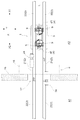
図1及び図4に示すように、左右一対の案内レール2は、開口17を貫通する状態で設置されて、第1エリアA1と第2エリアA2とに亘って配設されている。このように配設された案内レール2には、走行経路Lの経路長手方向Xで防火扉18が設置される扉設置箇所eに位置する移動案内部分21と、扉設置箇所eに対して経路長手方向Xの両側に位置する固定案内部分22と、が備えられている。
移動案内部分21は、扉設置箇所eに位置して固定案内部分22と連なる状態となる案内位置と、扉設置箇所eから退避して防火扉18の通過を許容する状態となる退避位置と、に変位自在に構成されていると共に、案内位置から退避位置への変位が移動案内部分21の自重により行われるように構成されている。
As shown in FIGS. 1 and 4, the pair of left and
The
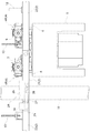
次に、左右一対の案内レール2について説明を加えるが、左右一対の案内レール2のうちの経路幅方向(左右方向)の一方側に位置する案内レール2を第1案内レール2aと称し、左右一対の案内レール2のうちの経路幅方向(左右方向)の他方側に位置する案内レール2を第2案内レール2bと称する。
また、第1案内レール2aの移動案内部分21を第1移動案内部分21aと称し、第2案内レール2bの移動案内部分21を第2移動案内部分21bと称する。更に、第1案内レール2aにおける第1移動案内部分21aに対して第1方向X1に連なる固定案内部分22を第1上流側固定案内部分22aと称し、第1案内レール2aにおける第1移動案内部分21aに対して第2方向X2に連なる固定案内部分22を第1下流側固定案内部分22bと称する。そして、第2案内レール2bにおける第2移動案内部分21bに対して第1方向X1に連なる固定案内部分22を第2上流側固定案内部分22cと称し、第2案内レール2bにおける第2移動案内部分21bに対して第2方向X2に連なる固定案内部分22を第2下流側固定案内部分22dと称する。
Next, the pair of left and
The
図4に示すように、第1移動案内部分21aは、当該第1移動案内部分21aにおける第1方向X1の端部に位置する経路幅方向に沿う揺動軸心周りに揺動自在に備えられている。第1移動案内部分21aの第2方向X2の端面は第1移動案内部分21aが案内位置に位置する状態において上方を向く傾斜面に形成され、第1下流側固定案内部分22bの第1方向X1の端面は下方を向く傾斜面に形成されている。
第1移動案内部分21aが案内位置に位置する状態では、第1移動案内部分21aの第2方向X2の端部と第1下流側固定案内部分22bの第1方向X1の端部とが上下方向視で重複しており、第1移動案内部分21aの案内位置より上方への揺動が、第1下流側固定案内部分22bに接触することで規制されている。
そして、第1移動案内部分21aは、案内位置から自重により揺動軸心周りに下方に揺動することで、案内位置から退避位置に移動するように構成されている。この退避位置は、第1移動案内部分21aの全体が扉設置箇所eに対して第1方向X1に位置する位置である。
As shown in FIG. 4, the first
In a state where the first
The first
第2移動案内部分21bは、当該第2移動案内部分21bにおける第2方向X2の端部に位置する経路幅方向に沿う軸心周りに揺動自在に備えられている。第2移動案内部分21bの第1方向X1の端面は第2移動案内部分21bが案内位置に位置する状態において上方を向く傾斜面に形成され、第2上流側固定案内部分22cの第1方向X1の端面は下方を向く傾斜面に形成されている。
第2移動案内部分21bが案内位置に位置する状態では、第2移動案内部分21bの第2方向X2の端部と第2上流側固定案内部分22cの第1方向X1の端部とが上下方向視で重複しており、第2移動案内部分21bの案内位置より上方への揺動が、第2上流側固定案内部分22cに接触することで規制されている。
そして、第2移動案内部分21bは、案内位置から自重により揺動軸心周りに下方に揺動することで、案内位置から退避位置に移動するように構成されている。この退避位置は、第2移動案内部分21bの全体が扉設置箇所eに対して第2方向X2に位置する位置である。
The second
In a state in which the second
The second
このように構成された移動案内部分21(第1移動案内部分21a及び第2移動案内部分21b)は、扉設置箇所eに位置して固定案内部分22と連なる状態となる案内位置と、扉設置箇所eから退避して防火扉18の通過を許容する状態となる退避位置と、に変位自在に構成されていると共に、案内位置から退避位置への変位が移動案内部分21の自重により行われるように構成されている。
The movement guide portion 21 (the first
第1上流側固定案内部分22aの第2方向端と第2上流側固定案内部分22cの第2方向端とが経路長手方向Xで同じ位置に位置するように、第1上流側固定案内部分22a及び第2上流側固定案内部分22cが配設されている。
また、第1下流側固定案内部分22bの第1方向端と第2下流側固定案内部分22dの第1方向端とが経路長手方向Xで同じ位置に位置するように、第1下流側固定案内部分22b及び第2下流側固定案内部分22dが配設されている。
The first upstream fixed
In addition, the first downstream side fixed guide so that the first direction end of the first downstream side fixed
図5に示すように、左右一対の案内レール2の夫々が、物品搬送車1に作動用の電力を給電する給電線14を経路長手方向Xに沿って備えている。
第1上流側固定案内部分22aが備える給電線14と、第1移動案内部分21aが備える給電線14と、第2上流側固定案内部分22cが備える給電線14とは、一連に構成されている。また、第2下流側固定案内部分22dが備える給電線14と、第2移動案内部分21bが備える給電線14と、第1下流側固定案内部分22bが備える給電線14とは、一連に構成されている。
そのため、第1移動案内部分21aが備える給電線14は、第1上流側固定案内部分22aが備える給電線14と接続され且つ第1下流側固定案内部分22bが備える給電線14と分断されている。
また、第2移動案内部分21bが備える給電線14は、第2下流側固定案内部分22dの給電線14と接続され且つ第2上流側固定案内部分22cが備える給電線14と分断されている。
As shown in FIG. 5, each of the pair of left and
The
Therefore, the
The
次に、物品搬送設備には、案内レール2の移動案内部分21を案内位置に保持する保持機構24が備えられている。次に、この保持機構24について説明する。
この保持機構24は、第1移動案内部分21a及び第2移動案内部分21bの夫々に対して備えられているが、同様に構成されているため、第1移動案内部分21aに対して備えられている保持機構24についてのみ説明する。
Next, the article transport facility is provided with a
The holding
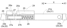
保持機構24は、第1被係合部25と、第2被係合部26と、係合体27と、スプリング28と、保持装置としての電磁石29と、を備えている。第1被係合部25は、第1移動案内部分21aの第2方向X2の端部に固定されている。第2被係合部26は、第1下流側固定案内部分22bの第1方向X1の端部に固定されている。係合体27は、係合位置において第1被係合部25及び第2被係合部26の双方に係合するように設けられている。スプリング28は、係合体27を係合位置から退避位置に向けて付勢する付勢体として設けられている。電磁石29は、係合体27の先端部27aを磁力により吸着保持して係合体27を係合位置に保持する保持装置として設けられている。
The holding
係合体27の基端部27bは、第1移動案内部分21aの長手方向に沿って摺動自在に第1被係合部25に常時係合している。係合体27は、基端部27bが第1被係合部25内を第1移動案内部分21aの長手方向に沿って摺動することで、係合体27の第1被係合部25からの突出量を増大させた係合位置と、係合体27の第1被係合部25からの突出量を減少させた解除位置とに、変位自在に構成されている。
スプリング28は、第1被係合部25に内装されており、係合体27を係合位置から解除位置に向けて付勢するように引っ張り状態で配設されている。
The
The
そして、案内レール2の第1移動案内部分21aが案内位置に位置している状態で、係合体27を経路長手方向Xに沿って移動させて、係合体27を係合位置に移動させることで、係合体27の先端部27aが第2被係合部26に係合する。そして、給電部34からの電力が電磁石29に供給されている状態では、その電磁石29にて磁力が発生しており、その磁力によりスプリング28の付勢力に抗して係合体27が係合位置に保持される。このように係合体27が第1被係合部25及び第2被係合部26の双方に係合している状態では、この係合体27にて第1移動案内部分21aが係合体27にて下方から支持される状態となり、第1移動案内部分21aは退避位置に保持される。
And in the state where the 1st movement guide
ちなみに、係合体27が係合位置に位置している状態では、係合体27の先端側が第1下流側固定案内部分22bに固定されている第2被係合部26に係合し且つ係合体27の基端側が第1移動案内部分21aに固定されている第1被係合部25に係合している。そのため、この係合位置は、案内位置にある状態の移動案内部分21と固定案内部分22とに係合して移動案内部分21を案内位置に保持する位置に相当する。
また、係合体27が解除位置に位置している状態では、係合体27の先端側が第1移動案内部分21aに固定されている第2被係合部26に係合していない。そのため、この解除位置は、移動案内部分21と固定案内部分22とのうちの一方の係合が解除される位置に相当する。
そして、係合体27は、移動案内部分21が案内位置から自重により移動する方向である鉛直下方に対して交差する水平方向(経路長手方向X)に変位自在に構成されている。
Incidentally, in a state where the engaging
Further, in a state where the
The engaging
そして、案内レール2の移動案内部分21を案内位置に位置させた状態で、係合体27を退避位置から係合位置に移動させると、図6に示すように、係合体27が第2被係合部26に係合する。このように係合体27が第2被係合部26に係合している状態では、第1移動案内部分21aが案内位置から退避位置に向けて移動することが規制されている。この係合体27の案内位置に位置する状態は、電磁石29の磁力により保持されている。
そして、このように電磁石29の磁力により係合体27が係合位置に保持されている状態において、給電部34から電磁石29への給電が遮断されると、電磁石29に発生していた磁力は消失するため、図7に示すように、係合体27はスプリング28の付勢力により係合体27が係合位置から解除位置に移動し、第1移動案内部分21aが自重により退避位置に移動するようになっている。
Then, when the
Then, in a state where the engaging
そして、係合体27は、電磁石29による磁力が作用していない場合において、第1移動案内部分21aに物品搬送車1の走行輪9が載っていない状態ではスプリング28の付勢力で係合位置から解除位置に移動可能であり、第1移動案内部分21aに物品搬送車1の走行輪9が載っている状態ではスプリング28の付勢力では係合位置から解除位置に移動しないように構成されている。
And when the magnetic force by the
説明を加えると、係合体27は円柱形状に形成されている。第2被係合部26には、係合体27の先端部27a(挿入部に相当)が挿入されて係合する係合凹部26aが備えられている。第1被係合部25には、係合体27の基端部27bが挿入されて係合している係合凹部25aが備えられている。係合体27の先端部27aは、挿入方向で先端側が基端側よりも細い先細り形状に形成されている
これら第1被係合部25の係合凹部25aと第2被係合部26の係合凹部26aとにより、固定案内部分22と移動案内部分21とに亘って形成された摺動路25a,26aが形成されている。
When the description is added, the
図2に示すように、第1移動案内部分21aに物品搬送車1の走行輪9が載っている状態では、走行輪9が載っていない状態に比べて、係合体27と摺動路25a,26aとの摩擦力が大きくなる。スプリング28の付勢力は、第1移動案内部分21aに物品搬送車1の走行輪9が載っていない状態での係合体27と摺動路25a,26aとの摩擦力より大きく、第1移動案内部分21aに物品搬送車1の走行輪9が載っている状態での係合体27と摺動路25a,26aとの摩擦力より小さく設定されている。
そのため、第1移動案内部分21aに物品搬送車1の走行輪9が載っていない状態では、スプリング28の付勢力により、係合体27と摺動路25a,26aとの摩擦力に抗して係合体27は係合位置から退避位置に移動する。また、第1移動案内部分21aに物品搬送車1の走行輪9が載っている状態では、係合体27と摺動路25a,26aとの摩擦力により、スプリング28の付勢力に抗して係合体27は係合位置に保持される。
As shown in FIG. 2, in the state where the traveling
Therefore, in a state where the traveling
次に、物品搬送設備に備えられている給電部34について説明する。
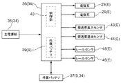
図8に示すように、給電部34には、無停電電源装置36が備えられており、無停電電源装置36は、主電源部35から電磁石29や各種センサ等の給電対象装置Eに対して電力を供給する給電経路の途中に設置されている。
この無停電電源装置36には、内装バッテリ39及び制御部40が内装されるとともに、外部バッテリ37が接続されている。外部バッテリ37と内装バッテリ39とで蓄電部Bが構成されている。制御部40は、主電源部35から供給される電力の電圧等に基づいて主電源部35の異常を判別可能に構成されており、主電源部35の異常を検出する主電源異常検出部として機能している。
このように、給電部34には、主電源部35と、蓄電部Bと、主電源部35の異常を検出する制御部40と、が備えられている。
Next, the
As shown in FIG. 8, the
The
As described above, the
そして、無停電電源装置36は、制御部40の制御により、主電源部35から電力が適正に供給されている状態では、主電源部35からの電力を給電対象装置Eに供給するとともに内装バッテリ39及び外部バッテリ37に蓄電するように構成されている。また、無停電電源装置36は、停電や給電電圧の異常等により主電源部35から電力が適正に供給されていない状態が制御部40にて検出されている状態(主電源部35に異常が検出された状態)では、蓄電部Bから給電対象装置Eに電力を供給するように構成されている。
The
図8に示すように、物品搬送設備には、無停電電源装置36の作動を外部から制御する給電制御部としての制御装置38と、火災を検出する火災検出装置42と、が備えられている。
制御装置38は、火災検出装置42から火災の発生を示す火災情報が出力された場合は、給電停止指令を無停電電源装置36に送信する。無停電電源装置36の制御部40は、制御装置38からの給電停止指令に基づいて、電磁石29に対する給電を停止し且つ電磁石29以外の給電対象装置Eに対する給電を維持するように構成されている。
As shown in FIG. 8, the article transport facility includes a
When the fire information indicating the occurrence of a fire is output from the fire detection device 42, the
このように、制御装置38は、給電部34の作動を制御して、火災検出装置42から火災の発生を示す火災情報が出力されていない間は、給電部34から電磁石29に電力が給電される給電状態を維持し、火災検出装置42から火災情報が出力されたことを条件に、給電部34から電磁石29に電力が供給されない給電停止状態に切り換えるように構成されている。
また、給電部34は、給電状態において主電源部35又は蓄電部Bから電磁石29に電力を供給するように構成され、かつ、給電状態において制御部40により主電源部35に異常が検出されると、蓄電部Bの電力を保持装置に供給するように構成され、かつ、給電停止状態において、主電源部35及び蓄電部Bのいずれからも電磁石29に電力を供給しないように構成されている。
In this way, the
The
次に、制御装置38による制御について説明を加える。
図9に示すように、物品搬送設備には、扉設置箇所eを含む監視区間に進入する物品搬送車1を検出する搬送車進入センサ43、監視区間から退出する物品搬送車1を検出する搬送車退出センサ44、案内レール2の移動案内部分21が退避位置に位置することを検出するレールセンサ45が備えられている。
Next, the control by the
As shown in FIG. 9, the article transport facility includes a transport
監視区間は、経路長手方向Xにおいて案内姿勢の移動案内部分21の全体が監視区間内に存在するように設定されており、監視区間内に物品搬送車1が進入しない限り物品搬送車1の走行輪9が移動案内部分21に載らないように設定されている。
搬送車進入センサ43は、監視区間の入口に設置され、搬送車退出センサ44は、監視区間の出口に設置されている。制御装置38は、搬送車進入センサ43の検出情報と搬送車退出センサ44の検出情報に基づいて、監視区間に物品搬送車1が存在するか否かを判別するように構成されている。
The monitoring section is set so that the entire
The transport
図10のフローチャートに基づいて制御装置38による制御について説明すると、制御装置38は、火災検出装置42からの火災情報が入力された場合において、監視区間に物品搬送車1が存在していないと判断した場合は、無停電電源装置36に給電停止指令を指令するように構成されている。ちなみに、制御装置38が無停電電源装置36に給電停止指令を指令することにより、無停電電源装置36による電磁石29に対する給電が遮断され、給電部34は給電停止状態に切り換えられる。これにより、電磁石29は磁力を消失し、係合体27がスプリング28の付勢力により係合位置から退避位置に移動して、移動案内部分21が退避位置に自重により落下する。
The control by the
また、制御装置38は、火災検出装置42からの火災情報が入力された場合において、監視区間に物品搬送車1が存在していると判断した場合は、物品搬送車1が監視区間から退出して監視区間を通過した後に、無停電電源装置36に給電停止指令を指令するように構成されている。また、制御装置38は、火災検出装置42からの火災情報が入力されてから予め設定された設定時間が経過した場合は、物品搬送車1が監視区間に存在するか否かに関わらず、無停電電源装置36に給電停止指令を指令するように構成されている。
Further, when the fire information from the fire detection device 42 is input and the
そして、制御装置38は、上述の如く無停電電源装置36に給電停止指令を指令した後、レールセンサ45にて第1移動案内部分21a及び第2移動案内部分21bの双方が退避位置に移動したことが検出されると、防火扉18を閉じ位置に移動させるべく、防火扉18の作動を制御するように構成されている。
Then, after instructing the
このように、電磁石29に電力が供給されない給電停止状態に給電部34を切り換えることで、移動案内部分21を退避位置に移動させることができるため、火災により停電が生じた場合でも、移動案内部分21を退避位置に移動させて、防火扉18を閉じることができる。
また、火災が発生していないために給電部34を給電状態に維持させて係合体27を係合位置に保持する場合でも、電磁石29の磁力は、スプリング28の付勢力に抗する力でよく、電磁石29の磁力により移動案内部分21を直接案内位置に保持する場合に比べて、電磁石29に供給する電力を抑えることができる。
Thus, since the
Further, even when the
〔別実施形態〕
(1)上記実施形態では、移動案内部分21が案内位置に位置する状態において係合体27を経路長手方向X(移動案内部分21の長手方向)に沿って摺動させることで、係合体27を係合位置と解除位置とに変位させるように構成したが、移動案内部分21が案内位置に位置する状態において係合体27を経路幅方向(移動案内部分21の幅方向)に沿って摺動させる、又は、移動案内部分21が案内位置に位置する状態で係合体27を上下方向(移動案内部分21の厚み方向)に沿う軸心周りに揺動させることで、係合体27を係合位置と解除位置とに変位させるように構成してもよい。
また、上記実施形態では、移動案内部分21の第2被係合部26に係合体27を常時係合させ、固定案内部分22の第2被係合部26に対して係合体27が係脱するように構成したが、固定案内部分22の第2被係合部26に係合体27を常時係合させ、係合体27の摺動又は揺動等の移動により、移動案内部分21の第1被係合部25に係合体27が係脱するように構成してもよい。
[Another embodiment]
(1) In the above-described embodiment, the
In the above embodiment, the
(2)上記実施形態では、第1移動案内部分21aを第1方向X1の端部に位置する軸心周りに揺動自在に備え、第2移動案内部分21bを第2方向X2の端部に位置する軸心周りに揺動自在に備えたが、第1移動案内部分21aと第2移動案内部分21bとの双方を、経路長手方向Xで同じ方向の端部に位置する軸心周りに揺動自在に備えてもよい。
また、上記実施形態では、給電線14からの給電により物品搬送車1に対して作動用の電力を供給したが、物品搬送車1にバッテリを備えて、そのバッテリからの給電により物品搬送車1に対して作動用の電力を供給するようにしてもよい。
(2) In the above-described embodiment, the first
Moreover, in the said embodiment, although the electric power for operation | movement was supplied with respect to the article conveyance vehicle 1 with the electric power feeding from the
(3)上記実施形態では、第2被係合部26に円柱形状の孔を形成して、その孔に係合体27の先端部27aを挿入する形状に形成したが、第2被係合部26における係合体27が係合する部分の形状は適宜変更してもよい。具体的には、例えば、上述の如く円柱形状の孔を形成することで、第2被係合部26の下部において下方に凹入する係合凹部26aを形成したが、第2被係合部26を、係合体27の移動方向視で角ばったU字状の溝に形成して、第2被係合部26に係合凹部26aを形成してもよい。また、第2被係合部26を平板状に形成して、その第2被係合部26上に係合体27の先端部27aが位置することで係合するように構成してもよい。
(3) In the above-described embodiment, a cylindrical hole is formed in the second engaged
(4)上記実施形態では、係合体27を、先細り形状に形成したが、係合体27を、挿入方向で太さが一定の円柱形状や四角柱状に形成する、又は、かぎ爪状に形成する等、係合体27の形状は適宜変更してもよい、
(4) In the above embodiment, the engaging
(5)上記実施形態では、物品搬送車1が案内レール2上を走行したが、物品搬送車1が床面上を走行してもよい。また、案内レール2を左右一対備えて左右一対の案内レール2にて物品搬送車1を案内したが、単一の案内レール2のみ備えて単一の案内レール2にて物品搬送車1を案内してもよい。
(5) In the above embodiment, the article transport vehicle 1 travels on the
(6)上記実施形態では、保持装置を、電磁石29にて構成して給電により発生した電磁石29の磁力により係合体27を係合位置に保持するように構成したが、保持装置としては、給電により係合体27を係合位置に保持する操作力を発生させる装置であればよく、例えば、保持装置を吸引装置にて構成して、給電により保持装置のモータを駆動させて吸引装置に吸引力を発生させ、その吸引力により係合体27を係合位置に保持するように構成してもよい。
(6) In the above embodiment, the holding device is configured by the
(7)上記実施形態では、防火扉18を、上下方向に移動することで閉じ位置と開き位置とに移動するように構成したが、防火扉18を、左右方向に移動させることで閉じ位置と開き位置とに移動するように構成してもよい。
(7) In the above embodiment, the
(8)上記実施形態では、第1移動案内部分21aと第2移動案内部分21bとの経路長手方向Xでの長さを同じ長さとしたが、第1移動案内部分21aと第2移動案内部分21bとの経路長手方向Xでの長さを異なる長さとしてもよい。また、第1移動案内部分21aと第2移動案内部分21bとを経路長手方向Xにおいて同じ位置に備えたが、第1移動案内部分21aと第2移動案内部分21bとを経路長手方向Xにおいて互いにずらした状態で備えてもよい。
(8) In the above embodiment, the first
1 物品搬送車
2 案内レール
9 走行輪
14 給電線
16 壁体
17 開口
18 防火扉
21 移動案内部分
21a 第1移動案内部分
21b 第2移動案内部分
22 固定案内部分
25a 摺動路、係合凹部
26a 摺動路、係合凹部
27 係合体
27a 先端部(挿入部)
28 スプリング(付勢体)
29 電磁石(保持装置)
34 給電部
35 主電源部
40 制御部(主電源異常検出部)
42 火災検出装置
B 蓄電部
H 制御装置(給電制御部)
L 走行経路
DESCRIPTION OF SYMBOLS 1
28 Spring (biasing body)
29 Electromagnet (holding device)
34
42 Fire detection device B Power storage unit H Control device (power supply control unit)
L Travel route
Claims (6)
前記物品搬送車を走行経路に沿って案内する案内レールと、
前記壁体の壁面に沿う移動により前記開口を閉鎖する防火扉と、を備え、
前記案内レールが、経路長手方向で前記防火扉が設置される扉設置箇所に位置する移動案内部分と、前記扉設置箇所に対して経路長手方向の両側に位置する固定案内部分と、を備え、
前記移動案内部分が、前記扉設置箇所に位置して前記固定案内部分と連なる状態となる案内位置と、前記扉設置箇所から退避して前記防火扉の通過を許容する状態となる退避位置と、に変位自在に構成されていると共に、前記案内位置から前記退避位置への変位が前記移動案内部分の自重により行われる物品搬送設備であって、
前記案内位置にある状態の前記移動案内部分と前記固定案内部分とに係合して前記移動案内部分を前記案内位置に保持する係合位置と、前記移動案内部分と前記固定案内部分との少なくとも一方の係合が解除される解除位置と、に前記移動案内部分が前記案内位置から自重により移動する方向に対して交差する方向に変位自在であって、前記係合位置にある状態で前記移動案内部分を下方から支持する係合体と、
前記係合体を前記係合位置から前記解除位置に向けて付勢する付勢体と、
給電部から供給される電力により操作力を発生させて当該操作力により前記付勢体の付勢力に抗して前記係合体を前記係合位置に保持する保持装置と、
前記給電部の作動を制御する給電制御部と、
火災を検出する火災検出装置と、が備えられ、
前記給電制御部が、前記給電部の作動を制御して、前記火災検出装置から火災の発生を示す火災情報が出力されていない間は、前記給電部から前記保持装置に電力が給電される給電状態を維持し、前記火災検出装置から前記火災情報が出力されたことを条件に、前記給電部から前記保持装置に電力が供給されない給電停止状態に切り換える物品搬送設備。 An article transport vehicle that travels along a travel route that passes through an opening formed in the wall, and
A guide rail for guiding the article transporter along a travel route;
A fire door that closes the opening by movement along the wall surface of the wall, and
The guide rail includes a moving guide portion located at a door installation location where the fire door is installed in the route longitudinal direction, and a fixed guide portion located on both sides in the route longitudinal direction with respect to the door installation location,
A guide position where the movement guide portion is located at the door installation location and connected to the fixed guide portion; a retreat position where the movement guide portion is retracted from the door installation location and allowed to pass through the fire door; And an article transport facility in which the displacement from the guide position to the retracted position is performed by the weight of the moving guide portion.
At least one of an engagement position that engages the movement guide portion and the fixed guide portion in the guide position and holds the movement guide portion at the guide position, and the movement guide portion and the fixed guide portion. The movement guide portion is displaceable in a direction intersecting with the release position where one of the engagements is released from the guide position due to its own weight, and the movement is performed when the engagement position is in the engagement position. An engagement body that supports the guide portion from below;
A biasing body that biases the engagement body from the engagement position toward the release position;
A holding device that generates an operating force by the electric power supplied from the power supply unit and holds the engaging body at the engagement position against the urging force of the urging body by the operating force;
A power supply control unit for controlling the operation of the power supply unit;
A fire detection device for detecting a fire, and
The power supply control unit controls the operation of the power supply unit, and power is supplied from the power supply unit to the holding device while fire information indicating the occurrence of a fire is not output from the fire detection device. An article transport facility that maintains a state and switches to a power supply stop state in which power is not supplied from the power supply unit to the holding device on condition that the fire information is output from the fire detection device.
前記給電部は、前記給電状態において前記主電源部又は前記蓄電部から前記保持装置に電力を供給するように構成され、かつ、前記給電状態において前記主電源異常検出部により前記主電源部に異常が検出されると、前記蓄電部の電力を前記保持装置に供給するように構成され、かつ、前記給電停止状態において、前記主電源部及び前記蓄電部のいずれからも前記保持装置に電力を供給しないように構成されている請求項1記載の物品搬送設備。 The power supply unit includes a main power supply unit, a power storage unit, and a main power supply abnormality detection unit that detects an abnormality of the main power supply unit,
The power supply unit is configured to supply power to the holding device from the main power supply unit or the power storage unit in the power supply state, and the main power supply unit is abnormal in the power supply state by the main power supply abnormality detection unit. Is detected, the power of the power storage unit is supplied to the holding device, and power is supplied to the holding device from either the main power supply unit or the power storage unit in the power supply stop state. The article conveyance facility according to claim 1, which is configured so as not to occur.
前記係合体は、前記保持装置による操作力が作用していない場合において、前記移動案内部分に前記物品搬送車の走行輪が載っていない状態では前記付勢体の付勢力で前記係合位置から前記解除位置に移動可能であり、前記移動案内部分に前記物品搬送車の走行輪が載っている状態では前記付勢体の付勢力では前記係合位置から前記解除位置に移動しないように構成されている請求項1又は2記載の物品搬送設備。 The guide rail includes a traveling surface on which traveling wheels of the article transport vehicle roll,
When the operating force by the holding device is not applied, the engagement body is moved from the engagement position by the urging force of the urging body when the traveling wheel of the article transport vehicle is not placed on the movement guide portion. It is configured to be movable to the release position, and not to move from the engagement position to the release position by the urging force of the urging body when the traveling wheel of the article transport vehicle is mounted on the movement guide portion. The article conveying facility according to claim 1 or 2.
前記付勢体の付勢力が、前記移動案内部分に前記物品搬送車の走行輪が載っていない状態での前記係合体と前記摺動路との摩擦力より大きく、前記移動案内部分に前記物品搬送車の走行輪が載っている状態での前記係合体と前記摺動路との摩擦力より小さく設定されている請求項3記載の物品搬送設備。 The engagement body slides along a slide path formed between the fixed guide portion and the movement guide portion and is displaced to the engagement position and the release position,
The urging force of the urging body is greater than the frictional force between the engagement body and the sliding path when the traveling wheel of the article transport vehicle is not placed on the movement guide portion, and the article is applied to the movement guide portion. The article conveyance facility according to claim 3, wherein the article conveyance facility is set to be smaller than a frictional force between the engagement body and the sliding path in a state where traveling wheels of the conveyance vehicle are placed.
前記物品搬送車が、左右一対の走行輪を備え、
左右一対の前記案内レールの夫々が、前記物品搬送車の走行輪が転動する走行面を備えるとともに、前記物品搬送車に作動用の電力を供給する給電線を前記経路長手方向に沿って備え、
前記移動案内部分が、左右一対の前記案内レールの一方における第1移動案内部分と左右一対の前記案内レールの他方における第2移動案内部分とを備え、
前記第1移動案内部分が、当該第1移動案内部分における前記第1方向の端部に位置する前記左右方向に沿う軸心周りに揺動自在に備えられ、前記第1移動案内部分が備える前記給電線が、前記第1移動案内部分に対して前記第1方向に連なる前記固定案内部分の前記給電線と接続され且つ前記第1移動案内部分に対して前記第2方向に連なる前記固定案内部分の前記給電線と分断されており、
前記第2移動案内部分が、当該第2移動案内部分における前記第2方向の端部に位置する前記左右方向に沿う軸心周りに揺動自在に備えられ、前記第2移動案内部分が備える前記給電線が、前記第2移動案内部分に対して前記第2方向に連なる前記固定案内部分の前記給電線と接続され且つ前記第2移動案内部分に対して前記第1方向に連なる前記固定案内部分の前記給電線と分断されている請求項1〜4のいずれか1項に記載の物品搬送設備。 One direction along the path longitudinal direction is the first direction, the other direction along the path longitudinal direction is the second direction, and the direction orthogonal to the path longitudinal direction in plan view is the left-right direction,
The article transport vehicle includes a pair of left and right traveling wheels,
Each of the pair of left and right guide rails includes a traveling surface on which traveling wheels of the article transport vehicle roll, and a power supply line that supplies operating power to the article transport vehicle along the longitudinal direction of the path. ,
The movement guide portion includes a first movement guide portion in one of the pair of left and right guide rails and a second movement guide portion in the other of the pair of left and right guide rails,
The first movement guide portion is provided so as to be swingable around an axial center along the left-right direction located at an end portion in the first direction of the first movement guide portion, and the first movement guide portion includes the first movement guide portion. The fixed guide portion connected to the feed line of the fixed guide portion connected in the first direction with respect to the first movement guide portion and connected in the second direction with respect to the first movement guide portion. Are separated from the feeder line,
The second movement guide portion is provided so as to be swingable around an axial center along the left-right direction located at an end of the second movement guide portion in the second direction, and the second movement guide portion includes the second movement guide portion. The fixed guide portion connected to the feed line of the fixed guide portion connected in the second direction with respect to the second movement guide portion and connected in the first direction with respect to the second movement guide portion. The article conveying facility according to any one of claims 1 to 4, wherein the article conveying facility is separated from the feeder line.
前記挿入部が、挿入方向で先端側が基端側よりも細い先細り形状に形成されている請求項1〜5のいずれか1項に記載の物品搬送設備。 The engagement body includes an insertion portion that is inserted into the engagement recess of the fixed guide portion,
The article insertion facility according to any one of claims 1 to 5, wherein the insertion portion is formed in a tapered shape in which the distal end side is thinner than the proximal end side in the insertion direction.
Priority Applications (6)
| Application Number | Priority Date | Filing Date | Title |
|---|---|---|---|
| JP2015131608A JP6327213B2 (en) | 2015-06-30 | 2015-06-30 | Goods transport equipment |
| TW105120325A TWI674999B (en) | 2015-06-30 | 2016-06-28 | Article transport facility |
| SG10201605312XA SG10201605312XA (en) | 2015-06-30 | 2016-06-28 | Article transport facility |
| US15/196,106 US10160464B2 (en) | 2015-06-30 | 2016-06-29 | Article transport facility |
| CN201610500853.0A CN106315145B (en) | 2015-06-30 | 2016-06-30 | Article conveying apparatus |
| KR1020160082425A KR102466809B1 (en) | 2015-06-30 | 2016-06-30 | Article transport facility |
Applications Claiming Priority (1)
| Application Number | Priority Date | Filing Date | Title |
|---|---|---|---|
| JP2015131608A JP6327213B2 (en) | 2015-06-30 | 2015-06-30 | Goods transport equipment |
Publications (2)
| Publication Number | Publication Date |
|---|---|
| JP2017013946A true JP2017013946A (en) | 2017-01-19 |
| JP6327213B2 JP6327213B2 (en) | 2018-05-23 |
Family
ID=57683862
Family Applications (1)
| Application Number | Title | Priority Date | Filing Date |
|---|---|---|---|
| JP2015131608A Active JP6327213B2 (en) | 2015-06-30 | 2015-06-30 | Goods transport equipment |
Country Status (6)
| Country | Link |
|---|---|
| US (1) | US10160464B2 (en) |
| JP (1) | JP6327213B2 (en) |
| KR (1) | KR102466809B1 (en) |
| CN (1) | CN106315145B (en) |
| SG (1) | SG10201605312XA (en) |
| TW (1) | TWI674999B (en) |
Cited By (3)
| Publication number | Priority date | Publication date | Assignee | Title |
|---|---|---|---|---|
| JP2018176950A (en) * | 2017-04-11 | 2018-11-15 | 村田機械株式会社 | Traveling vehicle system |
| JP2019059596A (en) * | 2017-09-27 | 2019-04-18 | 台湾大福高科技設備股▲分▼有限公司 | Article conveying device |
| JP2019119541A (en) * | 2017-12-28 | 2019-07-22 | 住友重機械搬送システム株式会社 | Automatic warehouse system |
Families Citing this family (10)
| Publication number | Priority date | Publication date | Assignee | Title |
|---|---|---|---|---|
| US10358147B2 (en) * | 2013-12-18 | 2019-07-23 | Luis Rodolfo Zamorano Morfín | Personalized elevated urban transport |
| JP6553639B2 (en) * | 2013-12-18 | 2019-07-31 | サモラノ モルフィン、ルイス ロドルフォ | Elevated urban transportation system for passengers |
| JP6358142B2 (en) * | 2015-03-26 | 2018-07-18 | 株式会社ダイフク | Goods transport equipment |
| JP6304122B2 (en) * | 2015-05-13 | 2018-04-04 | 株式会社ダイフク | Goods transport equipment |
| JP6870542B2 (en) * | 2017-08-31 | 2021-05-12 | 株式会社ダイフク | Goods transport equipment |
| JP6922853B2 (en) * | 2018-06-13 | 2021-08-18 | 株式会社ダイフク | Goods transport equipment |
| US10583985B2 (en) * | 2018-08-07 | 2020-03-10 | Daifuku Co., Ltd. | Article storage facility |
| CN109204383A (en) * | 2018-09-27 | 2019-01-15 | 广西曼彻彼斯自动化设备有限公司 | Logistics track double leval jib upper-turn-type broken rail device |
| CN113830530B (en) * | 2021-09-17 | 2023-05-30 | 德马科技集团股份有限公司 | Fireproof door transition device |
| CN115571544B (en) * | 2022-12-13 | 2023-03-21 | 上海速锐信息技术有限公司 | A emergent rail set for intelligent warehouse electric pallet truck |
Citations (2)
| Publication number | Priority date | Publication date | Assignee | Title |
|---|---|---|---|---|
| JPS61193105U (en) * | 1985-05-20 | 1986-12-01 | ||
| JPH061232A (en) * | 1992-06-19 | 1994-01-11 | Yamaha Motor Co Ltd | Rail interrupting mechanism of carrying device |
Family Cites Families (6)
| Publication number | Priority date | Publication date | Assignee | Title |
|---|---|---|---|---|
| DE2554272C2 (en) * | 1975-12-03 | 1978-02-02 | Mannesmann AG, 4000 Düsseldorf | Device for keeping an overhead conveyor track clear in the event of an alarm |
| JP2857308B2 (en) | 1993-12-16 | 1999-02-17 | トーヨーカネツ株式会社 | Relay unit between transfer devices |
| JP2006282140A (en) | 2005-04-05 | 2006-10-19 | Murata Mach Ltd | Transport vehicle system |
| CN101190748B (en) * | 2006-12-01 | 2011-09-07 | 台湾积体电路制造股份有限公司 | Automatization materials conveying system |
| CN201907529U (en) * | 2010-11-17 | 2011-07-27 | 上海美太医疗设备有限公司 | Rail turnover device |
| CN203173366U (en) * | 2013-02-16 | 2013-09-04 | 上海三禾服装物流设备制造有限公司 | Fireproof emergency device for conveyor line |
-
2015
- 2015-06-30 JP JP2015131608A patent/JP6327213B2/en active Active
-
2016
- 2016-06-28 TW TW105120325A patent/TWI674999B/en active
- 2016-06-28 SG SG10201605312XA patent/SG10201605312XA/en unknown
- 2016-06-29 US US15/196,106 patent/US10160464B2/en active Active
- 2016-06-30 KR KR1020160082425A patent/KR102466809B1/en active IP Right Grant
- 2016-06-30 CN CN201610500853.0A patent/CN106315145B/en active Active
Patent Citations (2)
| Publication number | Priority date | Publication date | Assignee | Title |
|---|---|---|---|---|
| JPS61193105U (en) * | 1985-05-20 | 1986-12-01 | ||
| JPH061232A (en) * | 1992-06-19 | 1994-01-11 | Yamaha Motor Co Ltd | Rail interrupting mechanism of carrying device |
Cited By (7)
| Publication number | Priority date | Publication date | Assignee | Title |
|---|---|---|---|---|
| JP2018176950A (en) * | 2017-04-11 | 2018-11-15 | 村田機械株式会社 | Traveling vehicle system |
| JP2019059596A (en) * | 2017-09-27 | 2019-04-18 | 台湾大福高科技設備股▲分▼有限公司 | Article conveying device |
| JP6990080B2 (en) | 2017-09-27 | 2022-01-12 | 台湾大福高科技設備股▲分▼有限公司 | Goods transport equipment |
| JP2019119541A (en) * | 2017-12-28 | 2019-07-22 | 住友重機械搬送システム株式会社 | Automatic warehouse system |
| JP7065601B2 (en) | 2017-12-28 | 2022-05-12 | 住友重機械搬送システム株式会社 | Automated warehouse system |
| JP2022097568A (en) * | 2017-12-28 | 2022-06-30 | 住友重機械搬送システム株式会社 | Automatic warehouse system |
| JP7342187B2 (en) | 2017-12-28 | 2023-09-11 | 住友重機械搬送システム株式会社 | automatic warehouse system |
Also Published As
| Publication number | Publication date |
|---|---|
| TW201704127A (en) | 2017-02-01 |
| CN106315145A (en) | 2017-01-11 |
| JP6327213B2 (en) | 2018-05-23 |
| CN106315145B (en) | 2020-01-14 |
| TWI674999B (en) | 2019-10-21 |
| SG10201605312XA (en) | 2017-01-27 |
| KR20170003474A (en) | 2017-01-09 |
| US10160464B2 (en) | 2018-12-25 |
| KR102466809B1 (en) | 2022-11-11 |
| US20170002523A1 (en) | 2017-01-05 |
Similar Documents
| Publication | Publication Date | Title |
|---|---|---|
| JP6327213B2 (en) | Goods transport equipment | |
| US20140069775A1 (en) | Article Transfer Device | |
| US8701864B2 (en) | Article transport facility | |
| US8448579B2 (en) | Article transport facility | |
| KR102636989B1 (en) | Article transport facility | |
| KR101464211B1 (en) | Carriage system having track | |
| US9934993B2 (en) | Article transport facility | |
| US9045147B2 (en) | Article transport facility | |
| JP7153129B2 (en) | injection molding system | |
| CN104470286B (en) | A kind of with the drawer type electric control cabinet assembly of warning device and position transducer | |
| US20190193950A1 (en) | Workpiece fixing tool, workpiece transport device, and robot system | |
| JP2019214322A (en) | Coupling device, conveyance device, and conveyance system | |
| US20160152450A1 (en) | Travel Facility | |
| US20190093290A1 (en) | Article Transport Facility | |
| JP2016081956A (en) | Component supply device | |
| JP2011132760A (en) | Rail device | |
| US20100117391A1 (en) | Transporting apparatus | |
| JP2012056664A (en) | Conveying system | |
| KR101490633B1 (en) | Looper | |
| JP6015980B2 (en) | Bar feeder and bar processing system | |
| KR101512763B1 (en) | Support structure for a ball screw | |
| JP4224792B2 (en) | Driving control device for traveling cart | |
| JP2007062888A (en) | Shelf device for physical distribution | |
| JP2007216941A (en) | Conveying device | |
| JP2007050793A (en) | Track for carriage cart |
Legal Events
| Date | Code | Title | Description |
|---|---|---|---|
| A621 | Written request for application examination |
Free format text: JAPANESE INTERMEDIATE CODE: A621 Effective date: 20170210 |
|
| A977 | Report on retrieval |
Free format text: JAPANESE INTERMEDIATE CODE: A971007 Effective date: 20171222 |
|
| A131 | Notification of reasons for refusal |
Free format text: JAPANESE INTERMEDIATE CODE: A131 Effective date: 20180109 |
|
| A521 | Request for written amendment filed |
Free format text: JAPANESE INTERMEDIATE CODE: A523 Effective date: 20180307 |
|
| TRDD | Decision of grant or rejection written | ||
| A01 | Written decision to grant a patent or to grant a registration (utility model) |
Free format text: JAPANESE INTERMEDIATE CODE: A01 Effective date: 20180320 |
|
| A61 | First payment of annual fees (during grant procedure) |
Free format text: JAPANESE INTERMEDIATE CODE: A61 Effective date: 20180402 |
|
| R150 | Certificate of patent or registration of utility model |
Ref document number: 6327213 Country of ref document: JP Free format text: JAPANESE INTERMEDIATE CODE: R150 |
|
| R250 | Receipt of annual fees |
Free format text: JAPANESE INTERMEDIATE CODE: R250 |
|
| R250 | Receipt of annual fees |
Free format text: JAPANESE INTERMEDIATE CODE: R250 |
|
| R250 | Receipt of annual fees |
Free format text: JAPANESE INTERMEDIATE CODE: R250 |
|
| R250 | Receipt of annual fees |
Free format text: JAPANESE INTERMEDIATE CODE: R250 |