JP2017013575A - Joint structure of refraction blockage rod - Google Patents
Joint structure of refraction blockage rod Download PDFInfo
- Publication number
- JP2017013575A JP2017013575A JP2015130548A JP2015130548A JP2017013575A JP 2017013575 A JP2017013575 A JP 2017013575A JP 2015130548 A JP2015130548 A JP 2015130548A JP 2015130548 A JP2015130548 A JP 2015130548A JP 2017013575 A JP2017013575 A JP 2017013575A
- Authority
- JP
- Japan
- Prior art keywords
- elastic member
- joint shaft
- blocking rod
- joint
- holder
- Prior art date
- Legal status (The legal status is an assumption and is not a legal conclusion. Google has not performed a legal analysis and makes no representation as to the accuracy of the status listed.)
- Pending
Links
Images


Landscapes
- Train Traffic Observation, Control, And Security (AREA)
Abstract
Description
本発明は、踏切遮断機に用いられる屈折形遮断桿の関節構造に関する。 The present invention relates to a joint structure of a refraction-type barrier rod used for a crossing barrier.
従来、踏切には人や自動車等の進入を制限するため、踏切遮断機が設けられている。踏切遮断機は、遮断機本体によって回動される遮断桿を水平方向に降下させて、踏切内への進入を遮断するようになっている。
そして、腕木式の踏切遮断機において、屈折形遮断桿が採用されたものが知られている(例えば、特許文献1、非特許文献1参照。)。屈折形遮断桿は、略水平な遮断位置と略鉛直な開放位置とに切り替えられる第1腕部の先端に関節部を介して第2腕部を連結した構造を有しており、第2腕部は遮断位置と開放位置の間で略水平な姿勢を維持するようになっている。
Conventionally, a railroad crossing barrier is provided at a railroad crossing to limit the entry of a person, a car, or the like. The level crossing breaker is configured to block the entry into the level crossing by lowering a blocking bar rotated by the breaker body in the horizontal direction.
In the arm-type railroad crossing barrier, a refraction-type barrier bar is adopted (see, for example,
ところで、踏切を通行する自動車が降下中の遮断桿の第2腕部と接触したり、踏切内に閉じ込められた自動車が踏切外に脱出する際に遮断桿の第2腕部と接触したりすることがある。
そのため、屈折形遮断桿の関節部には、第2腕部が自動車と接触した際の衝撃を緩和するために、屈曲変形や伸縮変形など弾性変形が可能なゴムなどの弾性部材が配設されている。
By the way, a car passing through a railroad crossing comes into contact with the second arm part of the barrier fence being lowered, or a car confined in the crossing makes contact with the second arm part of the barrier fence when it escapes outside the railroad crossing. Sometimes.
For this reason, an elastic member such as rubber that can be elastically deformed such as bending deformation and expansion / contraction deformation is disposed at the joint portion of the refraction type blocking arm in order to reduce the impact when the second arm portion comes into contact with the automobile. ing.
しかしながら、通行量が多い踏切では自動車と遮断桿が接触する頻度が高くなって、関節部の弾性部材が損傷し易いために、関節部のメンテナンスや弾性部材の交換を頻繁に行わなければならないという問題があった。 However, at a level crossing with a large amount of traffic, the frequency of contact between the car and the barrier is increased, and the elastic member of the joint part is easily damaged. There was a problem.
本発明の目的は、耐久性に優れた屈折形遮断桿の関節構造を提供することである。 An object of the present invention is to provide a joint structure of a refraction type blocking rod having excellent durability.
上記目的を達成するため、この発明は、
略水平な遮断位置と略鉛直な開放位置とに切り替えられる第1の遮断桿の先端部に第2の遮断桿を回動可能に連結する屈折形遮断桿の関節構造であって、
前記第1の遮断桿の先端部に当該第1の遮断桿の長手方向と直交する向きであって水平な姿勢をとるように設けられた関節軸と、
前記第2の遮断桿を保持するとともに、前記第2の遮断桿が前記遮断位置から前記開放位置までの間において略水平な姿勢を維持するように前記関節軸に回動可能に取り付けられるホルダーと、を備え、
前記ホルダーは、前記第2の遮断桿が取り付けられているホルダー本体と、前記ホルダー本体との間に前記関節軸を挟んで前記ホルダー本体に固定されるホルダー固定部と、を有し、
前記ホルダー固定部は、前記ホルダーの向きをずらすような方向の力が前記第2の遮断桿に作用した際に、前記関節軸に押し付けられる弾性部材と、前記関節軸に押し付けられた弾性部材の弾性変形を抑えるように前記弾性部材を挟持するカバー部材と、を備えるようにした。
In order to achieve the above object, the present invention provides:
A joint structure of a refraction-type blocking rod that pivotally connects a second blocking rod to the tip of the first blocking rod that can be switched between a substantially horizontal blocking position and a substantially vertical open position,
A joint shaft provided at a distal end portion of the first blocking rod so as to take a horizontal posture in a direction orthogonal to the longitudinal direction of the first blocking rod;
A holder that holds the second blocking rod and is rotatably attached to the joint shaft so that the second blocking rod maintains a substantially horizontal posture between the blocking position and the open position; With
The holder includes a holder main body to which the second blocking rod is attached, and a holder fixing portion that is fixed to the holder main body with the joint shaft interposed between the holder main body and the holder main body.
The holder fixing portion includes an elastic member that is pressed against the joint shaft when a force in a direction that shifts the orientation of the holder acts on the second blocking rod, and an elastic member that is pressed against the joint shaft. And a cover member for sandwiching the elastic member so as to suppress elastic deformation.
第1の遮断桿の先端部に連結されている第2の遮断桿に、例えば自動車が接触して第2の遮断桿が略水平方向に押されると、第2の遮断桿を保持しているホルダーの向きにずれが生じてホルダー固定部の弾性部材が関節軸に押し付けられる。その際、関節軸に押し付けられた弾性部材が弾性変形することで、第2の遮断桿に自動車が接触した際の衝撃を緩和することができ、ホルダーが損傷するのを低減するようになっている。
特に、関節軸に押し付けられる弾性部材には、その弾性部材の弾性変形を抑えるためのカバー部材が取り付けられているので、関節軸に押し付けられた弾性部材が押し潰れるように膨らみ過ぎる変形を抑えることができ、弾性部材に亀裂などの損傷が生じることを低減することができる。
For example, when an automobile comes into contact with the second barrier rod connected to the tip of the first barrier rod and the second barrier rod is pushed in a substantially horizontal direction, the second barrier rod is held. A deviation occurs in the direction of the holder, and the elastic member of the holder fixing portion is pressed against the joint shaft. At that time, the elastic member pressed against the joint shaft is elastically deformed, so that the impact when the automobile comes into contact with the second barrier rod can be mitigated, and the damage to the holder is reduced. Yes.
In particular, the elastic member that is pressed against the joint shaft is provided with a cover member for suppressing the elastic deformation of the elastic member, so that the elastic member that is pressed against the joint shaft is restrained from excessively bulging so as to be crushed. It is possible to reduce the occurrence of damage such as cracks in the elastic member.
ゴムなどの弾性材料からなる弾性部材は、圧縮される力に強いという特性を有しているので、弾性部材をカバー部材で挟持していても、関節軸に押し付けられた弾性部材が衝突などの衝撃を好適に吸収することができる。
このような屈折形遮断桿の関節構造であれば、第1の遮断桿の先端に連結されている第2の遮断桿に自動車などが接触した際の衝撃を緩和することは勿論のこと、弾性部材に亀裂などの損傷が生じ難くなっており、耐久性に優れた関節構造として好適に活用することができる。
An elastic member made of an elastic material such as rubber has a characteristic that it is strong against compressive force, so that even if the elastic member is sandwiched between cover members, the elastic member pressed against the joint shaft may An impact can be suitably absorbed.
With such a joint structure of the refraction type blocking rod, it is possible to reduce the impact when an automobile or the like comes into contact with the second blocking rod connected to the tip of the first blocking rod. The member is less likely to be damaged such as a crack, and can be suitably used as a joint structure having excellent durability.
また、望ましくは、
前記カバー部材は、前記関節軸に押し付けられた弾性部材がその関節軸の軸方向に広がる弾性変形を抑えるようにした。
Also, preferably
The cover member is configured to suppress elastic deformation of the elastic member pressed against the joint shaft extending in the axial direction of the joint shaft.
関節軸に押し付けられた弾性部材が、関節軸の軸方向に押し潰れて広がるように膨らむことを好適に抑えることで、弾性部材に亀裂などの損傷が生じることをより一層低減することができる。 It is possible to further reduce the occurrence of damage such as cracks in the elastic member by suitably suppressing the elastic member pressed against the joint shaft from being squeezed and expanded in the axial direction of the joint shaft.
また、望ましくは、
前記弾性部材が前記関節軸と接触する箇所には、前記関節軸の周面の形状に対応する凹面が形成されているようにした。
Also, preferably
A concave surface corresponding to the shape of the peripheral surface of the joint shaft is formed at a location where the elastic member contacts the joint shaft.
弾性部材が関節軸と接触する箇所に、関節軸の周面の形状に対応する凹面が形成されていれば、弾性部材と関節軸の接触面積を大きくすることができ、関節軸に押し付けられた弾性部材に応力集中させないようにして、弾性部材に亀裂などの損傷が生じることを抑えることができる。 If a concave surface corresponding to the shape of the peripheral surface of the joint shaft is formed at a location where the elastic member contacts the joint shaft, the contact area between the elastic member and the joint shaft can be increased and pressed against the joint shaft. It is possible to suppress the occurrence of damage such as cracks in the elastic member by not concentrating stress on the elastic member.
また、望ましくは、
前記カバー部材に挟持されている前記弾性部材は、前記カバー部材と前記弾性部材を連通する前記関節軸と平行なボルトによって固定されており、
前記ボルトを挿通させるように前記弾性部材に形成されている貫通穴は、前記第2の遮断桿の延在方向に沿う長穴であり、前記ボルトと前記関節軸の間に前記貫通穴の一部が露出するように、前記弾性部材が配設されているようにした。
Also, preferably
The elastic member sandwiched between the cover members is fixed by a bolt parallel to the joint shaft communicating the cover member and the elastic member,
A through hole formed in the elastic member so as to allow the bolt to pass therethrough is a long hole along the extending direction of the second blocking rod, and one of the through holes is provided between the bolt and the joint shaft. The elastic member is arranged so that the portion is exposed.
こうすることで、弾性部材をカバー部材に取り付けるためにボルトが挿通されている貫通穴の一部を、貫通穴に挿通させたボルトと弾性部材を離間させる空間にすることができる。そして、関節軸に押し付けられた弾性部材が相対的に関節軸に押されてボルト側に移動するように弾性変形することがあっても、その空間が干渉逃げ用の空間となり、弾性変形した弾性部材がボルトと接触することはない。
その結果、弾性部材の貫通穴が起点になる亀裂などの損傷が弾性部材に生じることを抑えることができる。
By doing so, a part of the through hole into which the bolt is inserted in order to attach the elastic member to the cover member can be made a space for separating the bolt inserted into the through hole and the elastic member. Even if the elastic member pressed against the joint shaft is relatively pressed by the joint shaft and elastically deforms so as to move to the bolt side, the space becomes a space for interference escape, and the elastically deformed elasticity The member does not contact the bolt.
As a result, it is possible to prevent the elastic member from being damaged such as a crack starting from the through hole of the elastic member.
本発明によれば、耐久性に優れた屈折形遮断桿の関節構造が得られる。 According to the present invention, it is possible to obtain a joint structure of a refraction type blocking rod excellent in durability.
以下、図面を参照して、本発明に係る屈折形遮断桿の関節構造の実施形態について詳細に説明する。但し、以下に述べる実施形態には、本発明を実施するために技術的に好ましい種々の限定が付されているが、本発明の範囲を以下の実施形態及び図示例に限定するものではない。 Hereinafter, with reference to the drawings, an embodiment of a joint structure of a refraction type blocking rod according to the present invention will be described in detail. However, the embodiments described below are given various technically preferable limitations for carrying out the present invention, but the scope of the present invention is not limited to the following embodiments and illustrated examples.
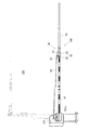
図1は、腕木式の踏切遮断機100を示す正面図である。
踏切遮断機100は、遮断機本体101と、遮断機本体101によって回動される屈折形遮断桿102とを備えて構成されている。
遮断機本体101の内部には、遮断桿を回動させる回転駆動機構が配設されている。なお、遮断機本体101の構成や動作は従来公知のものと同様であるので、ここでは詳述しない。
FIG. 1 is a front view showing a brace-type
The
Inside the
屈折形遮断桿102は、図1に示すように、遮断機本体101の腕金101aに取り付けられている第1の遮断桿としての根元遮断桿10と、根元遮断桿10の先端部に関節部30を介して連結されている第2の遮断桿としての先端遮断桿20とを備えている。また、一端が遮断機本体101の腕金101aに繋がれ、他端が屈折形遮断桿102の関節部30に繋がれているワイヤー40が所定のテンションが付与された状態で設けられている。
そして、根元遮断桿10は遮断機本体101によって水平な遮断位置と鉛直な開放位置とに切り替えられるようになっており、その根元遮断桿10に関節部30を介して回動可能に連結されている先端遮断桿20は、遮断位置と開放位置の間で水平な姿勢を維持するようになっている。
As shown in FIG. 1, the refraction
The
次に、本実施形態の屈折形遮断桿の関節構造に関し、屈折形遮断桿102の関節部30について説明する。
Next, regarding the joint structure of the refraction type blocking rod of this embodiment, the
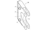
関節部30は、図1、図2に示すように、根元遮断桿10の先端部に根元遮断桿10と直交する向きに設けられ、遮断位置と開放位置の間で水平な姿勢をとる関節軸31と、先端遮断桿20を保持するとともに関節軸31に回動可能に取り付けられるホルダー32とを備えている。
As shown in FIGS. 1 and 2, the
ホルダー32は、先端遮断桿20が取り付けられているホルダー本体33と、ホルダー本体33との間に関節軸31を挟んでホルダー本体33に固定されるホルダー固定部34とを有している。また、ホルダー32には、ワイヤー40の他端が繋がれるワイヤー接続部35が設けられている。
このホルダー32は、ホルダー本体33に取り付けられた先端遮断桿20が遮断位置と開放位置の間で水平な姿勢を維持するように関節軸31に回動可能に軸支されている。
The
The
ホルダー本体33は、先端遮断桿20が取り付けられる基部33aと、関節軸31の両端にそれぞれ当接する二股部33bとを有している。
ホルダー固定部34は、ホルダー本体33の二股部33bにそれぞれボルト34aで締結されて固定されている。
このホルダー固定部34は、関節軸31に当接する弾性部材1と、弾性部材1を挟持しているカバー部材2とを備えている。カバー部材2に挟持されている弾性部材1は、カバー部材2と弾性部材1を連通するボルト3によって固定されている。このボルト3は、関節軸31と平行な向きに配設されている。
なお、対を成す二股部33bにそれぞれ固定されているホルダー固定部34はシンメトリーであるので、ホルダー固定部34の向きを変えることで左右どちらの二股部33bに固定しても使用することが可能になっている。
The holder
The
The
In addition, since the holder fixing | fixed
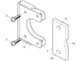
弾性部材1は、屈曲変形や伸縮変形といった弾性変形が可能なゴムなどの弾性材料からなる板状の部材である。
図3〜図5に示すように、弾性部材1は、その厚さ方向の両面が関節軸31と垂直になる向きに配設されており、弾性部材1が関節軸31と接触する箇所には、関節軸31の周面の形状に対応する凹面1aが形成されている。
また、弾性部材1には、図4、図5に示すように、ボルト3を挿通させるための貫通穴1bが形成されている。この貫通穴1bは、先端遮断桿20の延在方向に沿う長穴である。そして、図5に示すように、ボルト3と関節軸31の間(或いはボルト3とホルダー本体33の間)に貫通穴1bの一部が露出するように、弾性部材1がカバー部材2に配設されている。つまり、貫通穴1bの一部が、貫通穴1bに挿通させたボルト3と弾性部材1を離間させる空間になっている。
The
As shown in FIGS. 3 to 5, the
Further, as shown in FIGS. 4 and 5, the
カバー部材2は、図3、図4に示すように、板金加工によって形成された金属製の部材であり、弾性部材1の凹面1aが形成されている面以外の5面を囲う形状を有している。このカバー部材2は、弾性部材1の弾性変形を抑えるように弾性部材1を挟持している。
特に、カバー部材2は、弾性部材1の厚さ方向の両面であって、弾性部材1における関節軸31と垂直な2面と密接するように、弾性部材1を挟持している。
As shown in FIGS. 3 and 4, the
In particular, the
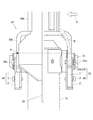
次に、屈折形遮断桿102の先端遮断桿20に自動車などが接触した際の関節部30の状態について説明する。
Next, the state of the
例えば、図6に示すように、先端遮断桿20に自動車などが接触して矢印Aの向きに先端遮断桿20が押された際、先端遮断桿20を保持しているホルダー32には、支点Pを回転中心とするように矢印Bの向きの回転トルクが作用する。
このように先端遮断桿20が略水平方向に押されてホルダー32の向きにずれが生じた際、ホルダー固定部34の弾性部材1は関節軸31に押し付けられる。そして、関節軸31に押し付けられた弾性部材1が弾性変形することで回転トルクのエネルギーを吸収し、先端遮断桿20が押された際の衝撃を緩和するようになっている。このように衝撃を緩和することでホルダー32が損傷するのを低減している。
For example, as shown in FIG. 6, when the
As described above, when the distal
特に、関節部30を構成するホルダー固定部34において、弾性部材1はカバー部材2に挟持されており、弾性部材1の厚さ方向の両面(ここでは弾性部材1における関節軸31と垂直な2面)がカバー部材2の内面と密接しているので、関節軸31に押し付けられた弾性部材1がその厚さ方向に膨らむ変形(ここでは関節軸31の軸方向に広がる変形)が抑えられるようになっている。
ゴムなどの弾性材料からなる弾性部材1は、圧縮される力に強いという特性を有しているので、弾性部材1をカバー部材2で挟持していても、関節軸31に押し付けられた弾性部材1が回転トルクのエネルギーを好適に吸収することができる。また、弾性部材1をカバー部材2が挟持していれば、弾性部材1が関節軸31に押し付けられ際に、弾性部材1が押し潰れてその厚さ方向に膨らみ過ぎる弾性変形を抑えて、弾性部材1に亀裂などの損傷が生じることを低減することができる。
In particular, in the
The
また、弾性部材1が関節軸31と接触する箇所に、関節軸31の周面の形状に対応する凹面1aを形成して、弾性部材1と関節軸31の接触面積を大きくすることによって、関節軸31に押し付けられた弾性部材1に応力集中させないようになっており、弾性部材1に亀裂などの損傷が生じることを抑えることができる。
Further, a
また、弾性部材1をカバー部材2に取り付けるためにボルト3が挿通されている貫通穴1bの一部が、貫通穴1bに挿通させたボルト3と弾性部材1を離間させる空間になっており、その空間がボルト3と関節軸31の間(或いはボルト3とホルダー本体33の間)にあるので、関節軸31に押し付けられた弾性部材1が相対的に関節軸31に押されてボルト3側に移動するように弾性変形することがあっても、その空間が干渉逃げ用の空間となり、弾性変形した弾性部材1がボルト3と接触することはない。その結果、貫通穴1bが起点になる亀裂などの損傷が弾性部材1に生じることを抑えることができる。
Moreover, in order to attach the
このように、本実施形態の屈折形遮断桿102の関節部30であれば、先端遮断桿20に自動車などが接触し、先端遮断桿20が略水平方向に押されてホルダー32の向きにずれが生じた場合、ホルダー固定部34の弾性部材1が関節軸31に押し付けられ、その弾性部材1が弾性変形することで、先端遮断桿20が押された際の衝撃を緩和することが可能になっている。
特に、ホルダー固定部34の弾性部材1をカバー部材2で挟持しているので、関節軸31に押し付けられた弾性部材1が関節軸31の軸方向に押し潰れて広がる変形を抑え、弾性部材1がその厚さ方向に膨らむ変形を抑えることができ、弾性部材1に亀裂などの損傷が生じることを低減することができる。
As described above, in the
In particular, since the
また、弾性部材1が関節軸31と接触する箇所に、関節軸31の周面の形状に対応する凹面1aを形成したことで、関節軸31に押し付けられた弾性部材1に応力集中させないようにすることができ、弾性部材1が関節軸31と接触する箇所が起点になる亀裂などの損傷が弾性部材1に生じることを抑えることができる。
また、弾性部材1をカバー部材2に取り付けるためにボルト3が挿通されている貫通穴1bの一部を、貫通穴1bに挿通させたボルト3と弾性部材1を離間させる空間にしたことで、関節軸31に押し付けられて弾性変形した弾性部材1がボルト3と接触させないようにすることができ、貫通穴1bが起点になる亀裂などの損傷が弾性部材1に生じることを抑えることができる。
Further, by forming the
In addition, by attaching a part of the through
以上のように、本実施形態の屈折形遮断桿102の関節部30に配設した弾性部材1は、先端遮断桿20に自動車などが接触した際の衝撃を緩和することは勿論のこと、亀裂などの損傷が生じ難くなっている。
従って、屈折形遮断桿102の関節部30は、耐久性に優れた屈折形遮断桿の関節構造として好適に活用することができる。
As described above, the
Therefore, the
なお、本発明の適用は上述した実施形態に限定されることなく、本発明の趣旨を逸脱しない範囲で適宜変更可能である。 The application of the present invention is not limited to the above-described embodiment, and can be appropriately changed without departing from the spirit of the present invention.
1 弾性部材
1a 凹面
1b 貫通穴
2 カバー部材
3 ボルト
10 根元遮断桿(第1の遮断桿)
20 先端遮断桿(第2の遮断桿)
30 関節部(関節構造)
31 関節軸
32 ホルダー
33 ホルダー本体
33a 基部
33b 二股部
34 ホルダー固定部
35 ワイヤー接続部
100 踏切遮断機
101 遮断機本体
101a 腕金
102 屈折形遮断桿
DESCRIPTION OF
20 Tip blocking rod (second blocking rod)
30 joints (joint structure)
31
Claims (4)
前記第1の遮断桿の先端部に当該第1の遮断桿の長手方向と直交する向きであって水平な姿勢をとるように設けられた関節軸と、
前記第2の遮断桿を保持するとともに、前記第2の遮断桿が前記遮断位置から前記開放位置までの間において略水平な姿勢を維持するように前記関節軸に回動可能に取り付けられるホルダーと、を備え、
前記ホルダーは、前記第2の遮断桿が取り付けられているホルダー本体と、前記ホルダー本体との間に前記関節軸を挟んで前記ホルダー本体に固定されるホルダー固定部と、を有し、
前記ホルダー固定部は、前記ホルダーの向きをずらすような方向の力が前記第2の遮断桿に作用した際に、前記関節軸に押し付けられる弾性部材と、前記関節軸に押し付けられた弾性部材の弾性変形を抑えるように前記弾性部材を挟持するカバー部材と、を備えたことを特徴とする屈折形遮断桿の関節構造。 A joint structure of a refraction-type blocking rod that pivotally connects a second blocking rod to the tip of the first blocking rod that can be switched between a substantially horizontal blocking position and a substantially vertical open position,
A joint shaft provided at a distal end portion of the first blocking rod so as to take a horizontal posture in a direction orthogonal to the longitudinal direction of the first blocking rod;
A holder that holds the second blocking rod and is rotatably attached to the joint shaft so that the second blocking rod maintains a substantially horizontal posture between the blocking position and the open position; With
The holder includes a holder main body to which the second blocking rod is attached, and a holder fixing portion that is fixed to the holder main body with the joint shaft interposed between the holder main body and the holder main body.
The holder fixing portion includes an elastic member that is pressed against the joint shaft when a force in a direction that shifts the orientation of the holder acts on the second blocking rod, and an elastic member that is pressed against the joint shaft. And a cover member for holding the elastic member so as to suppress elastic deformation.
前記ボルトを挿通させるように前記弾性部材に形成されている貫通穴は、前記第2の遮断桿の延在方向に沿う長穴であり、前記ボルトと前記関節軸の間に前記貫通穴の一部が露出するように、前記弾性部材が配設されていることを特徴とする請求項1〜3の何れか一項に記載の屈折形遮断桿の関節構造。 The elastic member sandwiched between the cover members is fixed by a bolt parallel to the joint shaft communicating the cover member and the elastic member,
A through hole formed in the elastic member so as to allow the bolt to pass therethrough is a long hole along the extending direction of the second blocking rod, and one of the through holes is provided between the bolt and the joint shaft. The joint structure of a refraction type blocking arm according to any one of claims 1 to 3, wherein the elastic member is disposed so that the portion is exposed.
Priority Applications (1)
| Application Number | Priority Date | Filing Date | Title |
|---|---|---|---|
| JP2015130548A JP2017013575A (en) | 2015-06-30 | 2015-06-30 | Joint structure of refraction blockage rod |
Applications Claiming Priority (1)
| Application Number | Priority Date | Filing Date | Title |
|---|---|---|---|
| JP2015130548A JP2017013575A (en) | 2015-06-30 | 2015-06-30 | Joint structure of refraction blockage rod |
Publications (1)
| Publication Number | Publication Date |
|---|---|
| JP2017013575A true JP2017013575A (en) | 2017-01-19 |
Family
ID=57827633
Family Applications (1)
| Application Number | Title | Priority Date | Filing Date |
|---|---|---|---|
| JP2015130548A Pending JP2017013575A (en) | 2015-06-30 | 2015-06-30 | Joint structure of refraction blockage rod |
Country Status (1)
| Country | Link |
|---|---|
| JP (1) | JP2017013575A (en) |
Cited By (1)
| Publication number | Priority date | Publication date | Assignee | Title |
|---|---|---|---|---|
| WO2019202826A1 (en) * | 2018-04-20 | 2019-10-24 | 株式会社音楽館 | Platform gate device |
-
2015
- 2015-06-30 JP JP2015130548A patent/JP2017013575A/en active Pending
Cited By (3)
| Publication number | Priority date | Publication date | Assignee | Title |
|---|---|---|---|---|
| WO2019202826A1 (en) * | 2018-04-20 | 2019-10-24 | 株式会社音楽館 | Platform gate device |
| JPWO2019202826A1 (en) * | 2018-04-20 | 2020-10-01 | 株式会社音楽館 | Platform gate device |
| CN111836750A (en) * | 2018-04-20 | 2020-10-27 | 株式会社音乐馆 | Gate device for platform |
Similar Documents
| Publication | Publication Date | Title |
|---|---|---|
| KR102115200B1 (en) | Dynamic damper | |
| JP5159770B2 (en) | Solar cell module device | |
| JP5650696B2 (en) | Mechanical stopper device having an elastic deformable body formed with a slit, and an articulated robot provided with the mechanical stopper device | |
| ES2650456T3 (en) | Vehicle chassis element structure with excellent impact resistance behavior | |
| JP2014523631A (en) | Battery module including an interconnection member having a vibration damping portion | |
| JP4270502B2 (en) | Engine mount | |
| JP4721722B2 (en) | Seismic control column base structure and seismic control structure using the same | |
| JP2017013575A (en) | Joint structure of refraction blockage rod | |
| KR100891473B1 (en) | Bumper reinforcement structrue for vehicle | |
| JP5961223B2 (en) | Pipe-shaped member and end sealing method thereof | |
| US10926741B2 (en) | Wiper bracket and wiper | |
| JP2016041969A (en) | Insulator | |
| JP5231934B2 (en) | Laminated rubber bearing | |
| JP2006322527A (en) | Braced viscoelastic damper | |
| JP5735027B2 (en) | Vibration isolator | |
| JP4466401B2 (en) | Laminated rubber support | |
| JP5823447B2 (en) | Double shock absorber | |
| JP6080361B2 (en) | Junction structure | |
| JP5261040B2 (en) | Damper mounting structure | |
| CN215211603U (en) | Expansion joint rigid grounding rod protection structure for concrete building structure | |
| JP2014181519A (en) | Seismic control device | |
| JP6218633B2 (en) | Vibration control device for columnar structure | |
| JP5662089B2 (en) | Gap cover device | |
| JP6092088B2 (en) | Steel bellows type damper | |
| KR101099051B1 (en) | vehicl frame mounted bush mount of torque rod mount |