JP2017013079A - Processing method of bearing device for wheel - Google Patents
Processing method of bearing device for wheel Download PDFInfo
- Publication number
- JP2017013079A JP2017013079A JP2015129434A JP2015129434A JP2017013079A JP 2017013079 A JP2017013079 A JP 2017013079A JP 2015129434 A JP2015129434 A JP 2015129434A JP 2015129434 A JP2015129434 A JP 2015129434A JP 2017013079 A JP2017013079 A JP 2017013079A
- Authority
- JP
- Japan
- Prior art keywords
- caulking
- wheel
- punch
- hub
- face spline
- Prior art date
- Legal status (The legal status is an assumption and is not a legal conclusion. Google has not performed a legal analysis and makes no representation as to the accuracy of the status listed.)
- Pending
Links
Images


Landscapes
- Mounting Of Bearings Or Others (AREA)
- Rolling Contact Bearings (AREA)
- Forging (AREA)
Abstract
Description
本発明は、自動車等の車両の車輪を回転自在に支承する車輪用軸受装置の加工方法に関し、特に、軸受部と等速自在継手とを着脱自在にユニット化した車輪用軸受装置の加工方法に関する。 The present invention relates to a processing method for a wheel bearing device that rotatably supports a wheel of a vehicle such as an automobile, and more particularly to a processing method for a wheel bearing device in which a bearing portion and a constant velocity universal joint are detachably unitized. .
自動車等の車両のエンジン動力を車輪に伝達する動力伝達装置は、エンジンから車輪へ動力を伝達すると共に、悪路走行時における車両のバウンドや車両の旋回時に生じる車輪からの径方向や軸方向変位、およびモーメント変位を許容する必要があるため、エンジン側と駆動車輪側との間に介装されるドライブシャフトの一端を摺動型の等速自在継手を介してディファレンシャルに連結し、他端を固定型の等速自在継手を含む車輪用軸受装置を介して車輪に連結している。 A power transmission device that transmits engine power of a vehicle such as an automobile to a wheel transmits power from the engine to the wheel, and also causes radial or axial displacement from the wheel that occurs when the vehicle bounces or turns when traveling on a rough road. In addition, one end of the drive shaft that is interposed between the engine side and the drive wheel side is connected to the differential via a sliding type constant velocity universal joint, and the other end is It is connected to the wheel via a wheel bearing device including a fixed type constant velocity universal joint.
近年、省資源あるいは公害等の面から燃費向上に対する要求は厳しいものがある。自動車部品において、中でも車輪用軸受装置の軽量化はこうした要求に応える要因として注目され、強く望まれて久しい。従来から軽量化を図った車輪用軸受装置に関する提案は種々のものがあるが、それと共に自動車等の組立現場あるいは補修市場において、組立・分解作業を簡略化して低コスト化を図ることも重要な要因となっている。 In recent years, demands for improving fuel efficiency have been severe from the viewpoint of resource saving or pollution. In automobile parts, weight reduction of a wheel bearing device has been noticed as a factor to meet such a demand and has been strongly desired for a long time. There are various proposals related to wheel bearing devices that have been reduced in weight, but it is also important to simplify the assembly and disassembly work and reduce the cost at the assembly site of automobiles and the repair market. It is a factor.
図6に示す車輪用軸受装置は、こうした要求を満たした代表的な一例である。この車輪用軸受装置は、ハブ輪51と複列の転がり軸受52と等速自在継手(図示せず)を着脱自在にユニット化した、所謂第3世代と称される構成を備えている。複列の転がり軸受52は、外方部材54と内方部材55と複列のボール56、56とを備えている。
The wheel bearing device shown in FIG. 6 is a typical example that satisfies these requirements. This wheel bearing device has a so-called third generation configuration in which a
外方部材54は、外周に車体(図示せず)に取り付けるための車体取付フランジ54bを一体に有し、内周には複列の外側転走面54a、54aが一体に形成されている。一方、内方部材55は、前記した外方部材54の複列の外側転走面54a、54aに対向する複列の内側転走面51a、57aが形成されている。これら複列の内側転走面51a、57aのうち一方の内側転走面51aがハブ輪51の外周に、他方の内側転走面57aが内輪57の外周にそれぞれ一体に形成されている。複列のボール56、56がこれら両転走面間にそれぞれ収容され、保持器58、58によって転動自在に保持されている。また、外方部材54と内方部材55との間に形成される環状空間の開口部にはシール61、62が装着され、軸受内部に封入された潤滑グリースの漏洩と、外部から軸受内部に雨水やダスト等が侵入するのを防止している。
The
ハブ輪51は、一端部に車輪(図示せず)を取り付けるための車輪取付フランジ59を一体に有し、外周に内側転走面51aと、この内側転走面51aから軸方向に延びる円筒状の小径段部51bが形成されている。この小径段部51bに内輪57が所定のシメシロを介して圧入されている。内輪57は、ハブ輪51の小径段部51bの端部を径方向外方に塑性変形させて形成した加締部60により、所定の軸受予圧が付与された状態でハブ輪51に対して軸方向に固定されている。
The
ここで、加締部60の端面にフェイススプライン53が形成されると共に、図示しない外側継手部材の肩部の端面に加締部60のフェイススプライン53に噛合するフェイススプラインが塑性加工によって形成されている。そして、肩部の雌ねじに螺合される固定ボルトによって対向する両フェイススプラインが圧接支持され、ハブ輪51と外側継手部材とが軸方向に分離可能に結合されている。
Here, the
ハブ輪51は、複数のノックピン63が立設された基台64上に、車輪取付フランジ59の車両外側の側面59bが当接した状態で縦型に載置され、車輪取付フランジ59に圧入されるハブボルト(図示せず)の挿入孔65にノックピン63が嵌挿されることにより支持固定されている。これにより、新たに固定手段を設けることなく基台上にハブ輪51を支持固定することができる。
The
また、塑性加工によって形成される小径段部51bの加締部60は、予め塑性加工前に円筒部66に形成されている。加締工具67は、一端面の中央部に鼻部68が突設され、この鼻部68の周縁から外周部に亙ってフェイススプライン53を塑性加工するための歯形69が形成されたパンチ70と、中心軸Aがハブ輪51の軸心Lに対して所定の傾斜角αが付与された揺動軸71とを備えている。パンチ70は、加締加工時にその位相がハブ輪51に対してずれないように、例えば、キー等の手段によって回転不可に揺動軸71に嵌着されている。ここでは、傾斜角αは4〜6°の範囲に設定されている。
Further, the
パンチ70の鼻部68は、この円筒部66の内径66aに対して所定の傾斜角βをもって円筒部66の端部に衝合するように形成されている。ここでは、傾斜角βは15〜35°の範囲に設定されている。
The
そして、加締工具67をハブ輪51の円筒部66に進入させ、パンチ70を円筒部66の端部に所定の加工力で押し当てると共に、ハブ輪51の軸心Lに一致した主軸(図示せず)を回転させることにより、加締工具67に揺動運動を発生させて塑性加工によって加締部60が形成され、同時に加締部60の端面にフェイススプライン53が形成される。
Then, the
こうした加締工具67を採用し、一体型のパンチ70によって、加締部60と、この加締部60の端面にフェイススプライン53とを同時に塑性加工によって形成するようにしたので、金型の構造が簡素化でき、金型加工やその組立および管理工数を削減して低コスト化を図ると共に、従来の加締加工のように、金型間に素材が噛み込み、バリの発生やこのバリの脱落片が滞留して作動性が低下するといった不具合を回避でき、加締部60やフェイススプライン53にバリが発生するのを防止して製品品質を向上させることができる(例えば、特許文献1参照。)。
By adopting such a
こうした車輪用軸受装置では、加締部60と同時にフェイススプライン53が揺動加締により形成されているので、作業性が向上すると共に、加工工数を削減させて低コスト化を図ることができる。然しながら、ハブ輪51は、例えば、S53C等の機械構造用炭素鋼を熱間鍛造後の状態、すなわち、未熱処理、所謂生の状態でフェイススプライン53を加工し、その歯部も熱処理しない状態で使用されるため、過大トルクが負荷された場合や、等速自在継手側のフェイススプラインとの噛合い精度が充分でない場合等、フェイススプライン53の歯部の変形や摩耗による係合部のガタが生じるといった問題があった。
In such a wheel bearing device, since the
本発明は、このような事情に鑑みてなされたもので、加締とフェイススプラインの形成工程を、歯型を形成した加締パンチで、加締加工とフェイススプラインの形成を同時に行う場合より、歯型を形成しない加締パンチで、加締部の粗成形を行った後、改めて歯型を形成した加締パンチでフェイススプラインを形成した方が、フェイススプライン歯部の加工硬化が大きいことに着目し、フェイススプライン加工を、所謂2段加締工程により形成することにより、歯部の機械的強度を向上させてクラックの発生を防止すると共に、耐摩耗を向上させて係合部のガタを防止して信頼性と寿命を向上させた車輪用軸受装置の加工方法を提供することを目的としている。 The present invention has been made in view of such circumstances, and the caulking and face spline forming process is performed by a caulking punch in which a tooth mold is formed and caulking and face spline are simultaneously formed. After rough forming of the crimped part with a crimping punch that does not form a tooth mold, face spline is formed with a crimping punch with a new tooth mold, and the work hardening of the face spline tooth part is greater. Attention is paid to form the face spline by a so-called two-step caulking process, thereby improving the mechanical strength of the tooth portion to prevent the occurrence of cracks and improving the wear resistance to reduce the backlash of the engaging portion. It aims at providing the processing method of the bearing apparatus for wheels which prevented and improved the reliability and lifetime.
係る目的を達成すべく、本発明のうち請求項1記載の発明は、内周に複列の外側転走面が一体に形成された外方部材と、一端部に車輪を取り付けるための車輪取付フランジを一体に有し、外周に軸方向に延びる円筒状の小径段部が形成されたハブ輪、およびこのハブ輪の小径段部に圧入された少なくとも一つの内輪からなり、前記複列の外側転走面に対向する複列の内側転走面が形成された内方部材と、この内方部材と前記外方部材の転走面間に転動自在に収容された複列の転動体とを備え、前記ハブ輪の小径段部を径方向外方に塑性変形させて形成した加締部により前記内輪が軸方向に固定されると共に、当該加締部の端面にトルク伝達用のフェイススプラインが形成された車輪用軸受装置の加工方法において、前記小径段部の端部が予め塑性加工前に円筒部に形成され、加締工具が、一端面の中央部に、前記円筒部の内径に対して所定の傾斜角をもって当該円筒部の端部に衝合する鼻部が突設され、この鼻部の周縁から外周部に亙って前記加締部を塑性加工するための形状に形成されたパンチと、このパンチが、加締加工時にその位相が前記ハブ輪に対してずれないように回転不可に嵌着され、中心軸が前記ハブ輪の軸心に対して所定の傾斜角が付与される揺動軸を備え、前記加締工具を前記ハブ輪に進入させ、前記パンチを前記円筒部の端部に所定の加工力で押し当てると共に、前記ハブ輪の軸心に一致した主軸を回転させることにより前記加締工具に揺動運動を発生させ、前記加締部が塑性変形により形成される第1工程と、加締工具が、前記鼻部の周縁から外周部に亙って前記フェイススプラインを塑性加工するための歯形が形成されたパンチと、このパンチが嵌着される前記揺動軸を備え、前記加締工具を前記ハブ輪に進入させ、前記パンチを前記加締部の端部に所定の加工力で押し当てると共に、前記主軸を回転させることにより前記加締工具に揺動運動を発生させ、前記フェイススプラインが塑性変形により形成される第2工程を備えている。
In order to achieve such an object, the invention according to
このように、ハブ輪の小径段部を径方向外方に塑性変形させて形成した加締部により内輪が軸方向に固定されると共に、当該加締部の端面にトルク伝達用のフェイススプラインが形成された車輪用軸受装置の加工方法において、小径段部の端部が予め塑性加工前に円筒部に形成され、加締工具が、一端面の中央部に、円筒部の内径に対して所定の傾斜角をもって当該円筒部の端部に衝合する鼻部が突設され、この鼻部の周縁から外周部に亙って加締部を塑性加工するための形状に形成されたパンチと、このパンチが、加締加工時にその位相がハブ輪に対してずれないように回転不可に嵌着され、中心軸がハブ輪の軸心に対して所定の傾斜角が付与された揺動軸を備え、加締工具をハブ輪に進入させ、パンチを円筒部の端部に所定の加工力で押し当てると共に、ハブ輪の軸心に一致した主軸を回転させることにより加締工具に揺動運動を発生させ、加締部が塑性変形により形成される第1工程と、加締工具が、鼻部の周縁から外周部に亙ってフェイススプラインを塑性加工するための歯形が形成されたパンチと、このパンチが嵌着された揺動軸を備え、加締工具をハブ輪に進入させ、パンチを加締部の端部に所定の加工力で押し当てると共に、主軸を回転させることにより加締工具に揺動運動を発生させ、フェイススプラインが塑性変形により形成される第2工程を備えているので、フェイススプラインの歯部の硬度を高めることができ、歯部の機械的強度を向上させてクラックの発生を防止すると共に、耐摩耗を向上させて係合部のガタを防止して信頼性と寿命を向上させた車輪用軸受装置の加工方法を提供することができる。また、2段階で加締部とフェイススプラインをそれぞれ形成するため、塑性変形の加工度が上がらず、歯部の成形性を高めることができるので精度を向上させることができる。 In this way, the inner ring is fixed in the axial direction by the caulking portion formed by plastically deforming the small-diameter step portion of the hub wheel radially outward, and a face spline for torque transmission is provided on the end surface of the caulking portion. In the formed wheel bearing device machining method, the end of the small-diameter stepped portion is formed in advance in the cylindrical portion before plastic working, and a crimping tool is provided at a central portion of one end surface with respect to the inner diameter of the cylindrical portion. A punch formed in a shape for plastic processing the crimping portion from the peripheral edge of the nose portion to the outer peripheral portion, with a nose portion projecting against the end portion of the cylindrical portion with an inclination angle of This punch is non-rotatably fitted so that its phase does not shift with respect to the hub wheel during caulking, and the center shaft has a swing shaft with a predetermined inclination angle with respect to the hub wheel axis. The caulking tool enters the hub wheel, and the punch is pushed to the end of the cylindrical part with a predetermined processing force. A first step in which a swiveling motion is generated in the caulking tool by rotating a main shaft that coincides with the axis of the hub wheel, and the caulking part is formed by plastic deformation; A punch having a tooth profile for plastic processing of the face spline from the peripheral edge to the outer peripheral portion thereof, and a swing shaft on which the punch is fitted, a caulking tool is inserted into the hub wheel, and the punch is Since it has a second step in which the face spline is formed by plastic deformation by pressing the end portion of the crimping portion with a predetermined processing force and generating a swinging motion in the crimping tool by rotating the spindle. , The hardness of the tooth part of the face spline can be increased, the mechanical strength of the tooth part is improved to prevent the occurrence of cracks, and the wear resistance is improved to prevent rattling of the engaging part and For wheels with improved service life It is possible to provide a processing method for receiving device. Further, since the caulking portion and the face spline are formed in two stages, the degree of plastic deformation does not increase, and the formability of the tooth portion can be improved, so that the accuracy can be improved.
好ましくは、請求項2に記載の発明は、前記フェイススプラインを成形する際、予め前記加締部が高周波誘導加熱によって150℃以下で加熱された後に加締加工されていれば、加工時に微小クラック等の発生を防止すると共に、フェイススプラインの成形性を向上させることができる。 Preferably, when the face spline is molded, if the crimping portion is preliminarily heated at 150 ° C. or less by high-frequency induction heating when forming the face spline, a microcrack is formed during the processing. And the like, and the formability of the face spline can be improved.
また、請求項3に記載の発明は、前記フェイススプラインの歯部の硬度が素材硬度よりHRCで10ポイント以上高くなるように設定されていれば、歯部の機械的強度と耐摩耗を向上させることができる。 Further, the invention according to claim 3 improves the mechanical strength and wear resistance of the tooth part if the hardness of the tooth part of the face spline is set to be 10 points or more higher than the material hardness in HRC. be able to.
また、請求項4に記載の発明は、前記フェイススプラインの歯部の硬度が32HRC以上に設定されていれば、歯部の機械的強度と耐摩耗を向上させることができ、長寿命化を図ることができる。
In the invention according to
また、請求項5に記載の発明のように、前記ハブ輪が、複数のノックピンが立設された基台上に、前記車輪取付フランジのアウター側の側面が当接した状態で縦型に載置され、前記車輪取付フランジに圧入されるハブボルトの挿入孔に前記ノックピンが嵌挿されることにより支持固定されていれば、新たに固定手段を設けることなく基台上にハブ輪を支持固定することができる。 According to a fifth aspect of the present invention, the hub wheel is mounted on the vertical type with the outer side surface of the wheel mounting flange in contact with a base on which a plurality of knock pins are erected. If the knock pin is inserted and inserted into the insertion hole of the hub bolt that is press-fitted into the wheel mounting flange, the hub ring is supported and fixed on the base without newly providing a fixing means. Can do.
また、請求項6に記載の発明のように、前記小径段部の円筒部の外周面に0.5〜1.0mmの深さで、両側に所定の曲率半径Ri、Roからなる円弧面を有する環状溝が形成され、これら円弧面のうちインナー側の円弧面の曲率半径Riがアウター側の円弧面の曲率半径Roよりも小さく、Ri≦Roに設定されると共に、当該環状溝が、前記内輪における内側転走面の大径端に対応する位置よりもインナー側から面取り部にかかり、大端面から所定の寸法だけ越えた範囲に形成されていれば、加締加工時に円筒部が変形し易くなり、加締加工による内輪の変形を抑制することができる。
Further, as in the invention described in
好ましくは、請求項7に記載の発明のように、前記内輪の面取り部が所定の曲率半径r1からなる円弧面を有し、この曲率半径r1よりも、前記環状溝におけるインナー側の円弧面の曲率半径Riが大きく、r1≦Riとなるように設定されていれば、加締加工による亀裂等の損傷を防止すると共に、内輪の変形を抑制することができる。
Preferably, as in the invention according to
本発明に係る車輪用軸受装置の加工方法は、内周に複列の外側転走面が一体に形成された外方部材と、一端部に車輪を取り付けるための車輪取付フランジを一体に有し、外周に軸方向に延びる円筒状の小径段部が形成されたハブ輪、およびこのハブ輪の小径段部に圧入された少なくとも一つの内輪からなり、前記複列の外側転走面に対向する複列の内側転走面が形成された内方部材と、この内方部材と前記外方部材の転走面間に転動自在に収容された複列の転動体とを備え、前記ハブ輪の小径段部を径方向外方に塑性変形させて形成した加締部により前記内輪が軸方向に固定されると共に、当該加締部の端面にトルク伝達用のフェイススプラインが形成された車輪用軸受装置の加工方法において、前記小径段部の端部が予め塑性加工前に円筒部に形成され、加締工具が、一端面の中央部に、前記円筒部の内径に対して所定の傾斜角をもって当該円筒部の端部に衝合する鼻部が突設され、この鼻部の周縁から外周部に亙って前記加締部を塑性加工するための形状に形成されたパンチと、このパンチが、加締加工時にその位相が前記ハブ輪に対してずれないように回転不可に嵌着され、中心軸が前記ハブ輪の軸心に対して所定の傾斜角が付与される揺動軸を備え、前記加締工具を前記ハブ輪に進入させ、前記パンチを前記円筒部の端部に所定の加工力で押し当てると共に、前記ハブ輪の軸心に一致した主軸を回転させることにより前記加締工具に揺動運動を発生させ、前記加締部が塑性変形により形成される第1工程と、加締工具が、前記鼻部の周縁から外周部に亙って前記フェイススプラインを塑性加工するための歯形が形成されたパンチと、このパンチが嵌着される前記揺動軸を備え、前記加締工具を前記ハブ輪に進入させ、前記パンチを前記加締部の端部に所定の加工力で押し当てると共に、前記主軸を回転させることにより前記加締工具に揺動運動を発生させ、前記フェイススプラインが塑性変形により形成される第2工程を備えているので、フェイススプラインの歯部の硬度を高めることができ、歯部の機械的強度を向上させてクラックの発生を防止すると共に、耐摩耗を向上させて係合部のガタを防止して信頼性と寿命を向上させた車輪用軸受装置の加工方法を提供することができる。また、2段階で加締部とフェイススプラインをそれぞれ形成するため、塑性変形の加工度が上がらず、歯部の成形性を高めることができるので精度を向上させることができる。 The processing method of the wheel bearing device according to the present invention integrally includes an outer member in which a double row outer rolling surface is integrally formed on the inner periphery, and a wheel mounting flange for mounting the wheel at one end. A hub ring having a cylindrical small-diameter step portion extending in the axial direction on the outer periphery, and at least one inner ring press-fitted into the small-diameter step portion of the hub ring, and facing the outer rolling surface of the double row An inner member formed with a double row inner rolling surface; and a double row rolling element that is slidably accommodated between the inner member and the rolling surface of the outer member. The inner ring is fixed in the axial direction by a caulking portion formed by plastically deforming a small-diameter step portion of the outer diameter in a radially outward direction, and a face spline for torque transmission is formed on an end surface of the caulking portion. In the processing method of the bearing device, the end portion of the small diameter step portion is previously cylindrical before plastic processing. The caulking tool is formed at the center of one end surface with a nose projecting into the end of the cylindrical part with a predetermined inclination angle with respect to the inner diameter of the cylindrical part. A punch formed in a shape for plastic working the caulking portion from the periphery to the outer peripheral portion, and the punch cannot be rotated so that the phase does not shift with respect to the hub wheel during caulking. A pivot shaft that is fitted and has a central axis that gives a predetermined inclination angle with respect to the axis of the hub wheel, the caulking tool is caused to enter the hub wheel, and the punch is inserted into an end of the cylindrical portion. And a pressing motion is generated on the caulking tool by rotating the main shaft that coincides with the axis of the hub wheel, and the caulking portion is formed by plastic deformation. 1 step and the caulking tool extends from the periphery of the nose part to the outer periphery part. A punch having a tooth profile for plastic processing of the line, and the swing shaft to which the punch is fitted, the caulking tool is inserted into the hub wheel, and the punch is moved to an end of the caulking portion. And a second step in which the face spline is formed by plastic deformation by causing the caulking tool to oscillate by rotating the main shaft while pressing against the part with a predetermined processing force. Can increase the hardness of the spline teeth, improve the mechanical strength of the teeth to prevent cracks, and improve wear resistance to prevent backlash of the engaging parts, thereby improving reliability and life An improved method for processing a wheel bearing device can be provided. Further, since the caulking portion and the face spline are formed in two stages, the degree of plastic deformation does not increase, and the formability of the tooth portion can be improved, so that the accuracy can be improved.
外周に懸架装置に取り付けられるための車体取付フランジを一体に有し、内周に複列の外側転走面が一体に形成された外方部材と、一端部に車輪を取り付けるための車輪取付フランジを一体に有し、外周に前記複列の外側転走面に対向する一方の内側転走面と、この内側転走面から軸方向に延びる円筒状の小径段部が形成されたハブ輪、およびこのハブ輪の小径段部に圧入され、外周に前記複列の外側転走面に対向する他方の内側転走面が形成された内輪からなる内方部材と、この内方部材と前記外方部材の転走面間に転動自在に収容された複列の転動体とを備え、前記ハブ輪の小径段部を径方向外方に塑性変形させて形成した加締部により前記内輪が軸方向に固定されると共に、当該加締部の端面にトルク伝達用のフェイススプラインが形成された車輪用軸受装置の加工方法において、前記小径段部の端部が予め塑性加工前に円筒部に形成され、加締工具が、一端面の中央部に、前記円筒部の内径に対して所定の傾斜角をもって当該円筒部の端部に衝合する鼻部が突設され、この鼻部の周縁から外周部に亙って前記加締部を塑性加工するための形状に形成されたパンチと、このパンチが、加締加工時にその位相が前記ハブ輪に対してずれないように回転不可に嵌着され、中心軸が前記ハブ輪の軸心に対して所定の傾斜角が付与される揺動軸を備え、前記加締工具を前記ハブ輪に進入させ、前記パンチを前記円筒部の端部に所定の加工力で押し当てると共に、前記ハブ輪の軸心に一致した主軸を回転させることにより前記加締工具に揺動運動を発生させ、前記加締部が塑性変形により形成される第1工程と、加締工具が、前記鼻部の周縁から外周部に亙って前記フェイススプラインを塑性加工するための歯形が形成されたパンチと、このパンチが嵌着される前記揺動軸を備え、前記加締工具を前記ハブ輪に進入させ、前記パンチを前記加締部の端部に所定の加工力で押し当てると共に、前記主軸を回転させることにより前記加締工具に揺動運動を発生させ、前記フェイススプラインが塑性変形により形成される第2工程を備え、前記フェイススプラインを成形する際、予め前記加締部が高周波誘導加熱によって150℃以下で加熱された後に加締加工されている。 An outer member integrally having a vehicle body mounting flange to be attached to the suspension device on the outer periphery, a double row outer rolling surface formed integrally on the inner periphery, and a wheel mounting flange for attaching a wheel to one end A hub wheel formed on the outer periphery with one inner rolling surface facing the outer rolling surface of the double row, and a cylindrical small diameter step portion extending in the axial direction from the inner rolling surface, An inner member comprising an inner ring that is press-fitted into a small-diameter step portion of the hub ring and has an outer ring formed on the outer periphery thereof that faces the outer rolling surface of the double row, and the inner member and the outer member. The inner ring is formed by a caulking portion formed by plastically deforming a small-diameter step portion of the hub wheel radially outward. A face spline for torque transmission is formed on the end face of the crimped part. In the wheel bearing device processing method, the end portion of the small diameter step portion is formed in advance in the cylindrical portion before plastic working, and a caulking tool is formed at the center portion of the one end surface with respect to the inner diameter of the cylindrical portion. A punch formed in a shape for plastic processing of the caulking portion from the peripheral edge of the nose portion to the outer peripheral portion with a predetermined inclination angle projecting to the end portion of the cylindrical portion. The punch is non-rotatably fitted so that its phase does not shift with respect to the hub wheel during caulking, and the central axis is given a predetermined inclination angle with respect to the axis of the hub wheel. A swing shaft is provided, the caulking tool enters the hub wheel, the punch is pressed against the end of the cylindrical portion with a predetermined processing force, and the main shaft that matches the axis of the hub wheel is rotated. As a result, a swinging motion is generated in the caulking tool, and the caulking portion is caused by plastic deformation. A first step to be formed; a punch in which a caulking tool is formed with a tooth profile for plastic working of the face spline from the periphery of the nose portion to the outer periphery; and the punch is fitted to the punch An oscillating shaft is provided, the caulking tool is advanced into the hub wheel, the punch is pressed against the end of the caulking portion with a predetermined processing force, and the main shaft is rotated to the caulking tool. A second step is provided in which the face spline is formed by plastic deformation by generating a swinging motion. When the face spline is formed, the crimping portion is heated after being heated at 150 ° C. or less by high-frequency induction heating in advance. It is tightened.
以下、本発明の実施の形態を図面に基づいて詳細に説明する。
図1は、本発明に係る車輪用軸受装置の一実施形態を示す縦断面図、図2は、図1の加締部の加工工程を示す説明図、図3(a)は、図2の要部拡大図、(b)は、(a)の要部拡大図、図4は、揺動加締の状態を示す説明図、図5は、図1のフェイススプラインの加工工程を示す説明図である。なお、以下の説明では、車両に組み付けた状態で車両の外側寄りとなる側をアウター側(図1の左側)、中央寄り側をインナー側(図1の右側)という。
Hereinafter, embodiments of the present invention will be described in detail with reference to the drawings.
FIG. 1 is a longitudinal sectional view showing an embodiment of a wheel bearing device according to the present invention, FIG. 2 is an explanatory view showing a machining process of the caulking portion of FIG. 1, and FIG. FIG. 4 is an explanatory view showing a state of swing caulking, and FIG. 5 is an explanatory view showing a processing process of the face spline in FIG. It is. In the following description, the side closer to the outer side of the vehicle when assembled to the vehicle is referred to as the outer side (left side in FIG. 1), and the side closer to the center is referred to as the inner side (right side in FIG. 1).
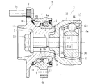
図1に示す車輪用軸受装置は、ハブ輪1と複列の転がり軸受2と等速自在継手3を着脱自在にユニット化した、所謂第3世代と称される構成を備えている。複列の転がり軸受2は、外方部材4と内方部材5と複列の転動体(ボール)6、6とを備えている。
The wheel bearing device shown in FIG. 1 has a so-called third generation configuration in which a
外方部材4はS53C等の炭素0.40〜0.80wt%を含む中高炭素鋼からなり、外周に車体(図示せず)に取り付けるための車体取付フランジ4bを一体に有し、内周には複列の外側転走面4a、4aが一体に形成されている。そして、少なくともこの複列の外側転走面4a、4aには、高周波焼入れによって表面硬さを58〜64HRCの範囲に硬化処理が施されている。
The
一方、内方部材5は、前記した外方部材4の外側転走面4a、4aに対向する複列の内側転走面1a、7aが形成されている。これら複列の内側転走面1a、7aのうち一方(アウター側)の内側転走面1aがハブ輪1の外周に、他方(インナー側)の内側転走面7aが内輪7の外周にそれぞれ一体に形成されている。この場合、内方部材5はハブ輪1と内輪7を指す。そして、複列の転動体6、6がこれら両転走面間にそれぞれ収容され、保持器8、8によって転動自在に保持されている。また、外方部材4と内方部材5との間に形成される環状空間の開口部にはシール11、12が装着され、軸受内部に封入された潤滑グリースの漏洩と、外部から軸受内部に雨水やダスト等が侵入するのを防止している。
On the other hand, the
ハブ輪1は、アウター側の端部に車輪(図示せず)を取り付けるための車輪取付フランジ9を一体に有し、外周に内側転走面1aと、この内側転走面1aから軸方向に延びる円筒状の小径段部1bが形成されている。この小径段部1bに内輪7が所定のシメシロを介して圧入されている。車輪取付フランジ9の周方向等配位置には車輪を固定するハブボルト9aが植設されている。そして、内輪7は、ハブ輪1の小径段部1bの端部を径方向外方に塑性変形させて形成した加締部10により、所定の軸受予圧が付与された状態でハブ輪1に対して軸方向に固定されている。
The
ハブ輪1はS53C等の炭素0.40〜0.80wt%を含む中高炭素鋼からなり、内側転走面1aをはじめ、アウター側のシール11が摺接するシールランド部から小径段部1bに亙る範囲に高周波焼入れによって表面硬さを58〜64HRCの範囲に所定の硬化処理が施されている。
The
内輪7はSUJ2等の高炭素クロム軸受鋼からなり、ズブ焼入れにより芯部まで58〜64HRCの範囲で硬化処理されている。また、転動体6はSUJ2等の高炭素クロム軸受鋼からなり、ズブ焼入れにより芯部まで62〜67HRCの範囲で硬化処理されている。これにより、車輪取付フランジ9の基部となるシールランド部は耐摩耗性が向上するばかりでなく、車輪取付フランジ9に負荷される回転曲げ荷重に対して充分な機械的強度を有し、ハブ輪1の耐久性が向上する。また、内輪7の嵌合面となる小径段部1bに発生するフレッティング摩耗を最小限に抑えることができる。
The
なお、ここでは、ハブ輪1の外周に内側転走面1aが直接形成された第3世代構造からなる車輪用軸受装置を例示したが、これに限らず、例えば、ハブ輪に一対の内輪が圧入された第2世代構造からなる車輪用軸受装置であっても良い。また、転動体6にボールを使用した複列のアンギュラ玉軸受を例示したが、転動体6に円錐ころを使用した複列の円錐ころ軸受であっても良い。
Here, the wheel bearing device having the third generation structure in which the inner raceway surface 1a is directly formed on the outer periphery of the
等速自在継手3は、外側継手部材13と継手内輪14とケージ15およびトルク伝達ボール16からなる。外側継手部材13は、カップ状のマウス部17と、このマウス部17の底部をなす肩部18とを有し、この肩部18の径方向中心部に雌ねじ18aが形成されている。また、マウス部17の内周および継手内輪14の外周には軸方向に延びる曲線状のトラック溝17a、14aがそれぞれ形成されている。また、外側継手部材13はS53C等の炭素0.40〜0.80wt%を含む中高炭素鋼からなり、継手内輪14はSCr420等の肌焼き鋼からなり、トラック溝17a、14aをはじめ、肩部18の外周面に高周波焼入れ、あるいは、浸炭焼入れによって表面硬さを58〜64HRCの範囲に硬化処理が施されている。
The constant velocity universal joint 3 includes an outer
本実施形態では、加締部10の端面にフェイススプライン19が形成されると共に、外側継手部材13の肩部18の端面に加締部10のフェイススプライン19に噛合するフェイススプライン20が塑性加工によって形成されている。そして、肩部18の雌ねじ18aに螺合される固定ボルト21によって対向する両フェイススプライン19、20が圧接支持され、ハブ輪1と外側継手部材13とが軸方向に分離可能に結合されている。
In the present embodiment, a
次に、図2乃至図4を用いて、図1の加締部10の加工方法を説明する。
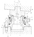
図2に示すように、複数のノックピン22が立設された基台23上に、ハブ輪1は、車輪取付フランジ9のアウター側の側面9bが当接した状態で縦型に載置され、車輪取付フランジ9に圧入されるハブボルト9aの挿入孔24にノックピン22が嵌挿されることにより支持固定されている。これにより、新たに固定手段を設けることなく基台23上にハブ輪1を支持固定することができる。
Next, the processing method of the crimping
As shown in FIG. 2, the
また、塑性加工によって形成される加締部10は、その加締部10となる部位が予め塑性加工前に円筒部30に形成されている。そして、図3に拡大して示すように、この円筒部30の外周面に深さδで、両側に曲率半径Ri、Roからなる円弧面を有する環状溝31が形成されている。これにより、加締加工時に円筒部30が変形し易くなって、内輪7に過大な応力が発生して変形するのを防止することができる。ただし、環状溝31は、内輪7における内側転走面7aの大径端に対応する位置よりもインナー側から内輪7の面取り部7cにかかり、大端面7bから寸法cだけ越えた範囲に形成されている。この環状溝31の幅は、大きくなるほどフープ応力が低下するが、余り大きくなると内輪押込み量が不足して所定の内輪固定力が得られないだけでなく、ハブ輪1の強度・剛性の低下に繋がり好ましくない。
Further, the
なお、環状溝31の深さδは0.5〜1.0mmの範囲に設定されている。この深さδが0.5mmよりも小さいとその効果が薄れ、また、深さδが1.0mmを超えると、加締部10の強度不足が懸念されるからである。また、インナー側の円弧面31aの曲率半径Riは、内輪7の面取り部7cの曲率半径r1よりも大きく、アウター側の円弧面31bの曲率半径Roよりも小さく設定され(r1≦Ri≦Ro)、Riが1〜10mmの範囲に設定されている。これにより、加締加工時に円筒部30が変形し易くなり、加締加工による内輪7の変形を抑制することができる。
The depth δ of the
なお、内輪7の面取り部7cの曲率半径r1を1.0mmよりも小さく設定すると、車両の運転中に曲げモーメント荷重が装置に負荷された時、加締部10の根元部分に応力集中が起こり、微小クラック等の損傷が発生する恐れがある。逆に、曲率半径r1が2.5mmを超えると、円筒部30を塑性変形する際、内輪7を径方向外方に押し広げることになり、内輪7の外径に過大なフープ応力が発生して好ましくない。
If the radius of curvature r1 of the chamfered
第1工程における加締工具25は、図2に示すように、一端面の中央部に鼻部26が突設されたパンチ27と、中心軸Aがハブ輪1の軸心Lに対して所定の傾斜角αが付与された揺動軸28とを備えている。パンチ27は、加締加工時にその位相がハブ輪1に対してずれないように、例えば、キー等の手段によって揺動軸28に対して回転不可に嵌着されている。ここでは、傾斜角αは4〜6°の範囲に設定されている。
As shown in FIG. 2, the
パンチ27の鼻部26は、円筒部30の内径30aに対して所定の傾斜角βをもって円筒部30の端部に衝合するように形成されている。ここでは、傾斜角βは15〜35°の範囲に設定されている。
The
ここで、図4に示すように、加締工具25をハブ輪1の円筒部30に進入させ、パンチ27を円筒部30の端部に所定の加工力で押し当てると共に、ハブ輪1の軸心Lに一致した主軸(図示せず)を回転させることにより、加締工具25に揺動運動を発生させて塑性加工によって加締部10が形成される。
Here, as shown in FIG. 4, the
加締部10となる円筒部30の素材硬度は19〜22HRCの範囲にあるのに対し、塑性加工によって形成される加締部10の表面硬度は、その加工硬化によって30〜32HRCに上昇している。
While the material hardness of the
本実施形態では、この加締加工の後、第2工程となるフェイススプライン19を形成するための2段加締が行われる。具体的には、図5に示すように、加締工具29は、一端面の中央部に鼻部26が突設され、この鼻部26の周縁から外周部に亙ってフェイススプライン19を塑性加工するための歯形32が形成されたパンチ33と、中心軸Aがハブ輪1の軸心Lに対して所定の傾斜角αが付与された揺動軸28とを備えている。
In the present embodiment, after this caulking process, two-stage caulking for forming the
そして、加締工具29をハブ輪1の加締部10に進入させ、パンチ33を加締部10の端部に所定の加工力で押し当てると共に、ハブ輪1の軸心Lに一致した主軸(図示せず)を回転させることにより、加締工具29に揺動運動を発生させて塑性加工によって加締部10の端面にフェイススプライン19が形成される。
Then, the
このフェイススプライン19を成形する際、予め加締部10を高周波誘導加熱によって
常温〜再結晶温度の範囲、具体的には、常温〜150℃の範囲に加熱した後、加締加工されている。これにより、加工時に微小クラック等の発生を防止すると共に、フェイススプライン19の成形性を向上させることができる。なお、ここでいう、「再結晶」とは、冷間加工等で塑性ひずみを受けた結晶が加熱されるとき、内部応力が減少する過程に続いて、ひずみが残っている元の結晶粒から内部ひずみのない新しい結晶の核が発生し、その数を増すと共に、各々の核は次第に成長して、元の結晶粒と置き換わっていく現象をいう。また、再結晶温度は、再結晶を起こす温度をいい、金属および合金の純度または組成、結晶内の塑性ひずみの程度、加熱の時間などによって著しい影響を受ける。したがって、加熱温度が150℃を超えると、さらに成形性を向上させることができる反面、加熱時間が長くなって作業効率が低下するだけでなく、グリースおよびシールのゴム材への熱影響や内輪の焼き戻し軟化があるため好ましくない。
When the
第1工程での塑性加工によって形成される加締部10の表面硬度が30〜32HRCに対して、第2工程の2段加締によるフェイススプライン19の表面硬度が32〜40HRCに上昇している。従来のように、加締部とフェイススプラインを同時に加締加工した場合、その表面硬度は29〜37HRCであるのに対し、本発明のようにフェイススプラインを2段加締によって形成した場合、HRC3ポイントの硬度上昇が得られる。
The surface hardness of the
こうした第1工程と第2工程からなる2段加締、すなわち、第1工程で加締部10を形成すると共に、第2工程で、この加締部10の端面にフェイススプライン19を塑性加工によって形成するようにしたので、フェイススプライン19の歯部の硬度を高めることができ、歯部の機械的強度を向上させてクラックの発生を防止すると共に、耐摩耗を向上させて係合部のガタを防止して信頼性と寿命を向上させた車輪用軸受装置の加工方法を提供することができる。また、2段階で加締部10とフェイススプライン19を形成するため、塑性変形の加工度が上がらず、歯部の成形性を高めることができるので精度を向上させることができる。
The two-step caulking composed of the first step and the second step, that is, the
以上、本発明の実施の形態について説明を行ったが、本発明はこうした実施の形態に何等限定されるものではなく、あくまで例示であって、本発明の要旨を逸脱しない範囲内において、さらに種々なる形態で実施し得ることは勿論のことであり、本発明の範囲は、特許請求の範囲の記載によって示され、さらに特許請求の範囲に記載の均等の意味、および範囲内のすべての変更を含む。 The embodiment of the present invention has been described above, but the present invention is not limited to such an embodiment, and is merely an example, and various modifications can be made without departing from the scope of the present invention. Of course, the scope of the present invention is indicated by the description of the scope of claims, and further, the equivalent meanings described in the scope of claims and all modifications within the scope of the scope of the present invention are included. Including.
本発明に係る駆動車輪用軸受装置は、ハブ輪を有する軸受部と等速自在継手とをフェイススプラインを介してトルク伝達可能に連結し、ねじ手段により両者を着脱自在にユニット化した車輪用軸受装置に適用することができる。 A bearing device for a driving wheel according to the present invention is a wheel bearing in which a bearing portion having a hub wheel and a constant velocity universal joint are connected via a face spline so that torque can be transmitted, and both are detachably unitized by screw means. It can be applied to the device.
1 ハブ輪
1a、7a 内側転走面
1b 小径段部
2 複列の転がり軸受
3 等速自在継手
4 外方部材
4a 外側転走面
4b 車体取付フランジ
5 内方部材
6 転動体
7 内輪
7b 大端面
7c 面取り部
8 保持器
9 車輪取付フランジ
9a ハブボルト
9b アウター側の側面
10 加締部
11、12 シール
13 外側継手部材
14 継手内輪
14a、17a トラック溝
15 ケージ
16 トルク伝達ボール
17 カップ部
18 肩部
18a 雌ねじ
19、20 フェイススプライン
21 固定ボルト
22 ノックピン
23 基台
24 挿入孔
25、29 加締工具
26 鼻部
27、33 パンチ
28 揺動軸
30 円筒部
30a 円筒部の内径
31 環状溝
32 歯形
51 ハブ輪
51a、57a 内側転走面
51b 小径段部
52 複列の転がり軸受
53 フェイススプライン
54 外方部材
54a 外側転走面
54b 車体取付フランジ
55 内方部材
56 ボール
57 内輪
58 保持器
59 車輪取付フランジ
59b 車輪取付フランジの側面
60 加締部
61、62 シール
63 ノックピン
64 基台
65 挿入孔
66 円筒部
66a 円筒部の内径
67 加締工具
68 鼻部
69 歯形
70 パンチ
71 揺動軸
A 揺動軸の中心軸
c 環状溝の内輪の大端面からの寸法
L ハブ輪の軸心
r1 内輪の面取り部の曲率半径
r2 環状溝の円弧面の曲率半径
Ri 環状溝におけるインナー側の円弧面の曲率半径
Ro 環状溝におけるアウター側の円弧面の曲率半径
α 揺動軸の傾斜角
β 鼻部の傾斜角
δ 環状溝の深さ
DESCRIPTION OF SYMBOLS 1 Hub wheel 1a, 7a Inner rolling surface 1b Small diameter step part 2 Double row rolling bearing 3 Constant velocity universal joint 4 Outer member 4a Outer rolling surface 4b Car body mounting flange 5 Inner member 6 Rolling body 7 Inner ring 7b Large end surface 7c Chamfered portion 8 Cage 9 Wheel mounting flange 9a Hub bolt 9b Outer side surface 10 Clamping portion 11, 12 Seal 13 Outer joint member 14 Joint inner ring 14a, 17a Track groove 15 Cage 16 Torque transmission ball 17 Cup portion 18 Shoulder portion 18a Female thread 19, 20 Face spline 21 Fixing bolt 22 Knock pin 23 Base 24 Insertion hole 25, 29 Clamping tool 26 Nose part 27, 33 Punch 28 Oscillating shaft 30 Cylindrical part 30a Cylindrical inner diameter 31 Annular groove 32 Tooth profile 51 Hub wheel 51a, 57a Inner rolling surface 51b Small diameter step 52 Double row rolling bearing 53 Face spline 54 Outer member 54a Outer rolling surface 54b Car body mounting flange 55 Inner member 56 Ball 57 Inner ring 58 Cage 59 Wheel mounting flange 59b Side surface 60 of the wheel mounting flange Clamping portion 61, 62 Seal 63 Knock pin 64 Base 65 Insertion hole 66 Cylindrical portion 66a Inner diameter 67 of cylindrical part 68 Nose part 69 Tooth shape 70 Punch 71 Oscillating axis A Center axis c of the oscillating axis L Dimension from large end surface of inner ring of annular groove L Center axis of hub ring r1 Curvature of chamfered part of inner ring Radius r2 Curvature radius Ri of the circular groove of the annular groove Radius of curvature Ro of the inner arc surface of the annular groove Ro Curvature radius of the outer circular surface of the annular groove α Inclination angle β of the oscillating shaft δ Inclination angle δ of the nose Depth of
Claims (7)
一端部に車輪を取り付けるための車輪取付フランジを一体に有し、外周に軸方向に延びる円筒状の小径段部が形成されたハブ輪、およびこのハブ輪の小径段部に圧入された少なくとも一つの内輪からなり、前記複列の外側転走面に対向する複列の内側転走面が形成された内方部材と、
この内方部材と前記外方部材の転走面間に転動自在に収容された複列の転動体とを備え、
前記ハブ輪の小径段部を径方向外方に塑性変形させて形成した加締部により前記内輪が軸方向に固定されると共に、
当該加締部の端面にトルク伝達用のフェイススプラインが形成された車輪用軸受装置の加工方法において、
前記小径段部の端部が予め塑性加工前に円筒部に形成され、
加締工具が、一端面の中央部に、前記円筒部の内径に対して所定の傾斜角をもって当該円筒部の端部に衝合する鼻部が突設され、この鼻部の周縁から外周部に亙って前記加締部を塑性加工するための形状が形成されたパンチと、
このパンチが、加締加工時にその位相が前記ハブ輪に対してずれないように回転不可に嵌着され、中心軸が前記ハブ輪の軸心に対して所定の傾斜角が付与される揺動軸を備え、
前記加締工具を前記ハブ輪に進入させ、前記パンチを前記円筒部の端部に所定の加工力で押し当てると共に、
前記ハブ輪の軸心に一致した主軸を回転させることにより前記加締工具に揺動運動を発生させ、前記加締部が塑性変形により形成される第1工程と、
加締工具が、前記鼻部の周縁から外周部に亙って前記フェイススプラインを塑性加工するための歯形が形成されたパンチと、
このパンチが嵌着される前記揺動軸を備え、
前記加締工具を前記ハブ輪に進入させ、前記パンチを前記加締部の端部に所定の加工力で押し当てると共に、
前記主軸を回転させることにより前記加締工具に揺動運動を発生させ、前記フェイススプラインが塑性変形により形成される第2工程を備えていることを特徴とする車輪用軸受装置の加工方法。 An outer member in which a double row outer rolling surface is integrally formed on the inner periphery;
A hub wheel integrally having a wheel mounting flange for mounting a wheel at one end and having a cylindrical small-diameter step portion extending in the axial direction on the outer periphery, and at least one press-fitted into the small-diameter step portion of the hub ring An inner member formed of two inner rings and formed with a double-row inner rolling surface facing the double-row outer rolling surface;
A double row rolling element housed in a freely rollable manner between the inner member and the rolling surface of the outer member,
The inner ring is fixed in the axial direction by a caulking portion formed by plastically deforming a small-diameter step portion of the hub wheel radially outward,
In the processing method of the wheel bearing device in which a face spline for torque transmission is formed on the end face of the crimped portion,
The end of the small diameter step is formed in the cylindrical portion in advance before plastic working,
A crimping tool has a nose projecting at the central portion of one end face with a predetermined angle of inclination with respect to the inner diameter of the cylindrical portion and projecting from the periphery of the nose to the outer peripheral portion. And a punch formed with a shape for plastic working the caulking portion,
This punch is non-rotatably fitted so that its phase does not shift with respect to the hub wheel during caulking, and the center axis is swung with a predetermined inclination angle with respect to the axis of the hub ring. With a shaft,
The caulking tool enters the hub wheel, the punch is pressed against the end of the cylindrical portion with a predetermined processing force,
A first step in which a swiveling motion is generated in the caulking tool by rotating a main shaft coinciding with an axis of the hub wheel, and the caulking portion is formed by plastic deformation;
A punch in which a caulking tool is formed with a tooth profile for plastic working the face spline from the periphery of the nose to the outer periphery,
The swing shaft to which this punch is fitted is provided,
The caulking tool enters the hub wheel, the punch is pressed against the end of the caulking portion with a predetermined processing force,
A processing method for a wheel bearing device, comprising: a second step in which a swinging motion is generated in the caulking tool by rotating the main shaft, and the face spline is formed by plastic deformation.
Priority Applications (1)
| Application Number | Priority Date | Filing Date | Title |
|---|---|---|---|
| JP2015129434A JP2017013079A (en) | 2015-06-29 | 2015-06-29 | Processing method of bearing device for wheel |
Applications Claiming Priority (1)
| Application Number | Priority Date | Filing Date | Title |
|---|---|---|---|
| JP2015129434A JP2017013079A (en) | 2015-06-29 | 2015-06-29 | Processing method of bearing device for wheel |
Publications (1)
| Publication Number | Publication Date |
|---|---|
| JP2017013079A true JP2017013079A (en) | 2017-01-19 |
Family
ID=57828656
Family Applications (1)
| Application Number | Title | Priority Date | Filing Date |
|---|---|---|---|
| JP2015129434A Pending JP2017013079A (en) | 2015-06-29 | 2015-06-29 | Processing method of bearing device for wheel |
Country Status (1)
| Country | Link |
|---|---|
| JP (1) | JP2017013079A (en) |
Cited By (5)
| Publication number | Priority date | Publication date | Assignee | Title |
|---|---|---|---|---|
| CN107824739A (en) * | 2017-11-08 | 2018-03-23 | 河南科技大学 | A kind of vertical knee-type milling machine Special curve bevel gear pendulum rolles over tool setting device |
| JP2020029936A (en) * | 2018-08-24 | 2020-02-27 | 日本精工株式会社 | Method and device for manufacturing bearing, method of manufacturing vehicle, and method of manufacturing machine device |
| CN110848239A (en) * | 2019-12-11 | 2020-02-28 | 苏州佳人良无纺布制品有限公司 | Bearing shaft and machining method thereof |
| WO2020208947A1 (en) * | 2019-04-10 | 2020-10-15 | 日本精工株式会社 | Method for manufacturing caulking assembly, method for manufacturing hub unit bearing, and method for manufacturing vehicle |
| JP7476850B2 (en) | 2019-04-10 | 2024-05-01 | 日本精工株式会社 | Method for manufacturing hub unit bearing and method for manufacturing vehicle |
-
2015
- 2015-06-29 JP JP2015129434A patent/JP2017013079A/en active Pending
Cited By (6)
| Publication number | Priority date | Publication date | Assignee | Title |
|---|---|---|---|---|
| CN107824739A (en) * | 2017-11-08 | 2018-03-23 | 河南科技大学 | A kind of vertical knee-type milling machine Special curve bevel gear pendulum rolles over tool setting device |
| JP2020029936A (en) * | 2018-08-24 | 2020-02-27 | 日本精工株式会社 | Method and device for manufacturing bearing, method of manufacturing vehicle, and method of manufacturing machine device |
| JP7180206B2 (en) | 2018-08-24 | 2022-11-30 | 日本精工株式会社 | Bearing manufacturing method and manufacturing device, vehicle manufacturing method, and mechanical device manufacturing method |
| WO2020208947A1 (en) * | 2019-04-10 | 2020-10-15 | 日本精工株式会社 | Method for manufacturing caulking assembly, method for manufacturing hub unit bearing, and method for manufacturing vehicle |
| JP7476850B2 (en) | 2019-04-10 | 2024-05-01 | 日本精工株式会社 | Method for manufacturing hub unit bearing and method for manufacturing vehicle |
| CN110848239A (en) * | 2019-12-11 | 2020-02-28 | 苏州佳人良无纺布制品有限公司 | Bearing shaft and machining method thereof |
Similar Documents
| Publication | Publication Date | Title |
|---|---|---|
| JP5261023B2 (en) | Processing method for wheel bearing device | |
| JP4063722B2 (en) | Wheel bearing device | |
| JP5355938B2 (en) | Drive wheel bearing device | |
| WO2014057770A1 (en) | Bearing device for wheel and manufacturing method therefor | |
| US20100239202A1 (en) | Double-row angular bearing, bearing device for wheel, method of producing outer race, and method of producing inner race | |
| JP2017013079A (en) | Processing method of bearing device for wheel | |
| JP4536086B2 (en) | Wheel bearing device and manufacturing method thereof | |
| JP2012197070A (en) | Manufacturing method for wheel rolling bearing device, and wheel rolling bearing device | |
| JP6468694B2 (en) | Wheel bearing device | |
| US7909517B2 (en) | Wheel support bearing assembly and manufacturing method thereof | |
| JP5331334B2 (en) | Drive wheel bearing device | |
| JP2007100715A (en) | Bearing device for vehicle | |
| JP2008045718A (en) | Bearing unit | |
| JP6224402B2 (en) | Method for manufacturing outer member of wheel bearing device | |
| JP2012132568A (en) | Wheel bearing | |
| JP2009162335A (en) | Bearing device for wheel | |
| JP2008057599A (en) | Bearing device for wheel | |
| JP2008207586A (en) | Wheel bearing device and its manufacturing method | |
| JP6429441B2 (en) | Wheel bearing device, intermediate body, and manufacturing method thereof | |
| JP2007315508A (en) | Bearing device for wheel | |
| JP2008057713A (en) | Wheel bearing device | |
| EP2684709A1 (en) | Shaft member for rolling bearing device for wheel | |
| JP2012184813A (en) | Shaft member of rolling bearing for wheel and method for manufacturing the same | |
| JP2014206192A (en) | Bearing device for wheel | |
| JP2008144946A (en) | Wheel bearing device |