JP2017009221A - Dehumidification intake and exhaust unit, double skin system and dehumidification intake and exhaust method - Google Patents
Dehumidification intake and exhaust unit, double skin system and dehumidification intake and exhaust method Download PDFInfo
- Publication number
- JP2017009221A JP2017009221A JP2015126592A JP2015126592A JP2017009221A JP 2017009221 A JP2017009221 A JP 2017009221A JP 2015126592 A JP2015126592 A JP 2015126592A JP 2015126592 A JP2015126592 A JP 2015126592A JP 2017009221 A JP2017009221 A JP 2017009221A
- Authority
- JP
- Japan
- Prior art keywords
- intake
- air
- exhaust
- exhaust unit
- distribution port
- Prior art date
- Legal status (The legal status is an assumption and is not a legal conclusion. Google has not performed a legal analysis and makes no representation as to the accuracy of the status listed.)
- Granted
Links
Images


Abstract
Description
本発明は、ダブルスキン構造の窓ガラスにおける中間層の空気の流れを制御する吸排気ユニット、及び中間層の内部結露を防止する除湿ユニット、並びにそれらを用いたダブルスキンシステムに関する。 The present invention relates to an intake / exhaust unit that controls the flow of air in an intermediate layer in a window glass having a double skin structure, a dehumidifying unit that prevents internal condensation in the intermediate layer, and a double skin system using them.
従来の建物においては、窓ガラスとして一枚の板ガラスが用いられていることが多く、非常に熱効率が悪い状態である。板ガラスは熱が出入りしやすいため、室内の日の当たる側は暑くなり、室内の奥の方は寒い状態である。室内において温度のバラつきがあると、冷暖房機器の効きも悪くなり、エネルギー効率も悪い。すなわち、室内を適温に維持するために熱が有効活用されていない。 In conventional buildings, a single sheet glass is often used as the window glass, which is in a very poor thermal efficiency. Since the glass sheet is easy to get heat in and out, the sunny side of the room is hot and the back of the room is cold. If the temperature varies in the room, the effectiveness of the air-conditioning equipment will be poor and the energy efficiency will be poor. That is, heat is not effectively utilized to maintain the room at an appropriate temperature.
特許文献1に記載されているように、板ガラス(外ガラス)の室内側にインナーガラス(内ガラス)を設置してダブルスキン構造にすることにより、冷房時には日射等による窓面熱負荷の低減を図り、暖房時には日射等により暖められた空気を熱回収することで暖房効率を高めることができるダブルガラススキン用のインナーガラススキン構造の発明も開示されている。特に、冬季における暖気利用は、室内からの吸気、中間層での熱交換、室内への排気の経路で実現できる省エネ手法であり、従来の手法においては簡便に構築するのは難しい。
As described in
窓ガラスをダブルスキン構造にするにあたり、まず、中間層におけるガラスのクリーニングやブラインドのメンテナンス等を、メンテナンスデッキを設けずに実施できることが必要である。なお、特許文献1に記載の発明では解決済みである。次に、外ガラスと内ガラスの間に設けた中間層における空気制御を簡便かつ確実にし、少ないメンテナンスで長期間の実用に耐える必要がある。
In order to make the window glass into a double skin structure, it is first necessary to be able to perform glass cleaning and blind maintenance in the intermediate layer without providing a maintenance deck. The invention described in
中間層で空気制御を行う場合、外ガラス側に吸排気口を上下に設け、それを手動又は自動操作で開閉させて外気吸入又は排出を行う。なお、アルミ製のカーテンウォール(取り外し可能な壁)において、横材又は縦材の中に外気導入機構を組み入れたシステムも存在する。ただし、自然吸排気であるため、風向や風速の変化等によって吸排気性能が変わり、その効果を予測することが難しい。 When air control is performed in the intermediate layer, intake and exhaust ports are provided at the top and bottom on the outer glass side, and are opened or closed manually or automatically to perform intake or exhaust of outside air. In addition, in an aluminum curtain wall (removable wall), there is a system in which an outside air introduction mechanism is incorporated in a cross member or a vertical member. However, since it is natural intake / exhaust, the intake / exhaust performance changes due to changes in wind direction and wind speed, and it is difficult to predict the effect.
外気と直接に接していない内ガラス側は、少なくとも耐震性能を有していれば良いが、中間層に外気を取り入れることから耐風圧性能も考慮する。内ガラス側の耐風圧性能は、外ガラス側の吸排気口の面積と開条件下での風速から決定されるが、安全性の見地からその数倍を想定しておく必要がある。なお、運用可能な風速は、吸排気口の面積にも依るが、毎秒10メートル程度であり、特に中間層内にブラインドが設置される場合は、それを超えると吸排気が困難となる。さらに、外気を吸入するにあたり、吸排気口にフィルターを設置することが難しく、内部メンテナンスの回数が増えてしまう。 The inner glass side that is not in direct contact with the outside air only needs to have at least a seismic performance, but since the outside air is taken into the intermediate layer, the wind pressure performance is also considered. The wind pressure resistance performance on the inner glass side is determined from the area of the intake / exhaust port on the outer glass side and the wind speed under open conditions, but it is necessary to assume several times from the viewpoint of safety. Although the operable wind speed depends on the area of the intake / exhaust port, it is about 10 meters per second. In particular, when a blind is installed in the intermediate layer, it becomes difficult to intake / exhaust. Furthermore, when inhaling outside air, it is difficult to install a filter at the intake and exhaust ports, and the number of internal maintenance increases.
自然吸排気の場合、設計風圧力に対して完全密閉又は開放を長期間確実に実現する性能も求められる。長期間使用しないと密閉材の固着や操作機構の故障もあり得るので、それを想定したメンテナンス計画も必要となる。また、強風時又は降雨時、特に暴風時における吸排気口の閉め忘れは、中間層の内圧を上げ、ブラインドや内ガラス側に影響を与える等、大きな問題を引き起こす。上記のような問題を克服しようとすると、高コストにならざるを得ないのが現状である。 In the case of natural intake / exhaust, performance is also required to ensure complete sealing or opening for a long period of time against the design wind pressure. If it is not used for a long period of time, the sealing material may be stuck or the operation mechanism may be broken, so a maintenance plan that assumes that is also necessary. Also, forgetting to close the intake and exhaust ports during strong winds or rain, especially during storms, raises the internal pressure of the intermediate layer and causes serious problems such as affecting the blinds and the inner glass side. In order to overcome the above problems, the current situation is that the cost must be high.
窓ガラスを、特許文献1に記載されているようなダブルスキン構造にしても、中間層に空気が滞留するなど熱を有効活用できなければ意味がない。また、熱を有効活用するために設備が複雑になったり、高コストになったり、効果が弱かったりしても意味がない。それらを解消することができれば、ダブルスキン構造を導入することへのハードルは低くなる。
Even if the window glass has a double skin structure as described in
また、ダブルスキン構造の窓ガラスにおいて、外ガラス(アウターガラス)の中間層側に内部結露が発生する問題もある。外気に対して窓ガラスの開口部が密閉状態の場合に、外ガラスにより隔てられた外気によって中間層が急に冷やされ、中間層内の温度が露点まで下がると、外ガラスの内側に結露が生じる。自動車のショールームその他の建物において、窓ガラスに内部結露が発生することは好ましくない。 Moreover, in the window glass of a double skin structure, there also exists a problem that an internal dew condensation generate | occur | produces in the intermediate | middle layer side of outer glass (outer glass). When the opening of the window glass is sealed against the outside air, the interlayer is suddenly cooled by the outside air separated by the outside glass, and when the temperature in the interlayer drops to the dew point, condensation forms on the inside of the outside glass. Arise. In automobile showrooms and other buildings, it is not preferable that internal condensation occurs on the window glass.
そこで、本発明は、ダブルスキン構造の窓ガラスにおける中間層の空気の流れを簡単に制御する吸排気ユニット及びそれを用いたダブルスキンシステムを提供することを目的とする。 Accordingly, an object of the present invention is to provide an intake / exhaust unit for easily controlling the air flow in the intermediate layer of a double-skin structure window glass and a double skin system using the same.
さらに、本発明は、ダブルスキン構造の窓ガラスにおいて、中間層の内部結露を防止する除湿吸排気ユニット及びそれを用いたダブルスキンシステムを提供することを別の目的とする。 Furthermore, another object of the present invention is to provide a dehumidification / exhaust / exhaust unit that prevents internal condensation in the intermediate layer and a double skin system using the same in a window glass having a double skin structure.
上記の課題を解決するために、第一の発明である除湿吸排気ユニットは、空気が出入りする第1の分配口と、前記第1の分配口とは区分けされた空気が出入りする第2の分配口と、前記第1及び2の分配口とは区分けされた空気が出入りする第3の分配口と、前記第1、2及び3の分配口とは区分けされた空気が出入りする第4の分配口と、吸引した空気を送出するファンと、前記ファンによって空気が吸引される側であって、前記第1、2、3又は4の分配口と繋がる吸気孔が空けられた負圧路と、前記ファンによって空気が排出される側であって、前記第1、2、3又は4の分配口と繋がる排気孔が空けられた正圧路と、排出された空気の湿度を調整する除湿手段と、を備え、前記第1、2、3又は4のうち何れかの分配口から空気を吸引し、前記第1、2、3又は4のうち前記吸引している以外の何れかの分配口へ空気を送出し、前記第1、2、3又は4のうち何れかの分配口から送出された場合に、空気の湿度を前記除湿手段で調整した上で送出する、ことを特徴とする。 In order to solve the above-described problems, a dehumidification / intake / exhaust unit according to a first aspect of the present invention includes a first distribution port through which air enters and exits and a second air through which the air separated from the first distribution port enters / exits. A distribution port, a third distribution port through which the separated air enters and exits the first and second distribution ports, and a fourth air through which the divided air enters and exits from the first, second, and third distribution ports. A distribution port, a fan for sending out the sucked air, and a negative pressure path in which air is sucked by the fan, and an intake hole connected to the first, second, third, or fourth distribution port is formed. A positive pressure path on the side from which air is discharged by the fan and having an exhaust hole connected to the first, second, third or fourth distribution port, and a dehumidifying means for adjusting the humidity of the discharged air And sucks air from any one of the first, second, third and fourth distribution ports. Then, air is sent to any one of the first, second, third or fourth distribution ports other than the suction port, and is sent from any one of the first, second, third or fourth distribution ports. In this case, the air humidity is adjusted by the dehumidifying means and sent out.
また、第一の発明である除湿吸排気ユニットは、太陽電池で発生させた電気を蓄積し、前記ファンに電気を供給する蓄電池を備える、ことを特徴とする。 The dehumidifying / exhaust / exhaust unit according to the first aspect of the invention includes a storage battery that accumulates electricity generated by a solar cell and supplies electricity to the fan.
また、第一の発明である除湿吸排気ユニットは、前記負圧路が、複数の吸気孔をシャッターで開口又は閉口することによって前記第1、2、3又は4の分配口と繋げられ、前記正圧路が、複数の排気孔をシャッターで開口又は閉口することによって前記第1、2、3又は4の分配口と繋げられる、ことを特徴とする。 Further, in the dehumidifying / intake / exhaust unit according to the first invention, the negative pressure path is connected to the first, second, third, or fourth distribution ports by opening or closing a plurality of intake holes with a shutter, The positive pressure path is connected to the first, second, third, or fourth distribution port by opening or closing a plurality of exhaust holes with a shutter.
第二の発明であるダブルスキンシステムは、第一の発明である除湿吸排気ユニットを、室外側に配される外ガラスと、室内側に配される内ガラスと、前記外ガラスと前記内ガラスの間の中間層とからなるダブルスキン構造の窓ガラスの上部と下部に設置し、前記吸排気ユニットが、前記前記室外側と前記室内側と前記中間層の間で空気の吸排気を行う、ことを特徴とする。 The double skin system which is the second invention includes the dehumidification / exhaust unit according to the first invention, the outer glass disposed on the outdoor side, the inner glass disposed on the indoor side, the outer glass and the inner glass. Installed in the upper and lower portions of the double-skin structure window glass composed of an intermediate layer between, the intake and exhaust unit performs air intake and exhaust between the outdoor side, the indoor side and the intermediate layer, It is characterized by that.
第三の発明である除湿吸排気方法は、第二の発明であるダブルスキンシステムにおいて、前記下部の吸排気ユニットが、前記室外側又は前記室内側から吸入した空気を前記中間層に排出し、前記上部の吸排気ユニットが、前記中間層から吸入した空気を前記室外側又は前記室内側に排出する、ことを特徴とする。 The dehumidification / intake / exhaust method according to the third invention is the double skin system according to the second invention, wherein the lower intake / exhaust unit discharges the air sucked from the outdoor side or the indoor side to the intermediate layer, The upper intake / exhaust unit discharges air sucked from the intermediate layer to the outdoor side or the indoor side.
本発明である吸排気ユニットによってダブルスキン構造の窓ガラスにおける中間層の空気の流れを制御することにより、容易に中間層で温まった空気を室内に取り入れることもできるし、室外に排気することもできる。そして、吸排気ユニットを用いたダブルスキンシステムを、建物の窓ガラスに採用することにより、簡単に建物の熱効率を向上させることができる。 By controlling the air flow of the intermediate layer in the double-skin structure window glass by the intake / exhaust unit according to the present invention, the air warmed in the intermediate layer can be easily taken into the room or exhausted outside the room. it can. And the thermal efficiency of a building can be easily improved by employ | adopting the double skin system using an intake / exhaust unit for the window glass of a building.
また、本発明である吸排気ユニットに除湿ユニットを組み合わせることにより、ダブルスキン構造の窓ガラスにおいて、中間層の内部結露を防止することができる。外気温の低下に合わせて中間層内を乾燥させることもできるし、また中間層内が乾燥している場合は湿度を上げることも可能である。 Further, by combining the dehumidifying unit with the intake / exhaust unit according to the present invention, it is possible to prevent internal condensation of the intermediate layer in the double-skin structure window glass. The inside of the intermediate layer can be dried in accordance with a decrease in the outside air temperature, and the humidity can be increased when the inside of the intermediate layer is dry.
以下に、本発明の実施形態について図面を参照して詳細に説明する。なお、同一機能を有するものは同一符号を付け、その繰り返しの説明は省略する場合がある。 Embodiments of the present invention will be described below in detail with reference to the drawings. In addition, what has the same function attaches | subjects the same code | symbol, and the repeated description may be abbreviate | omitted.
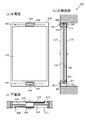
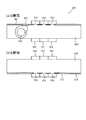
まず、本発明である吸排気ユニットを用いたダブルスキンシステムについて説明する。図1(a)はダブルスキンシステムを採用した窓ガラスの正面図であり、図1(b)はダブルスキンシステムを採用した窓ガラスの右側面図であり、図1(c)はダブルスキンシステムを採用した窓ガラスの平面図である。ダブルスキンシステム100は、建物に複数設置される窓ガラスの各々に採用される構成であり、図1(a)に示すように、少なくとも、ダブルスキン200、上側の吸排気ユニット300、及び下側の吸排気ユニット301などを備える。
First, a double skin system using the intake / exhaust unit according to the present invention will be described. FIG. 1A is a front view of a window glass employing a double skin system, FIG. 1B is a right side view of the window glass employing a double skin system, and FIG. 1C is a double skin system. It is a top view of the window glass which employ | adopted. The
ダブルスキン200は、窓ガラスの開口部であり、図1(b)に示すように、少なくとも、外ガラス210、及び内ガラス220などを備える。外ガラス210としては、既存の窓ガラスと同様の板ガラスなどを使用する。内ガラス220としては、断熱性のある複層ガラスなどを使用する。複層ガラスは、複数枚の板ガラスを重ね、その間に空気やその他の気体を封入したもの、又はその間を真空状態にしたものである。
The
外ガラス210は室外側に配置され、熱が出入りしやすいが、内ガラス220は室内側に配置され、熱が出入りしにくい。外ガラス210と内ガラス220とは、重ねる際に所定の隙間を設けて配置することで、中間層230を設ける。中間層230は、空気が出入り可能な空間である。外ガラス210を介して室外から中間層230に入った熱によって空気は暖められるが、その熱は内ガラス220を介して中間層230から室内には入りにくい。
The
また、中間層230にはブラインド240を配しても良い。ブラインド240は、横長のルーバーを縦に複数配置したもので、各ルーバーの角度を変えることにより、室外から取り込まれる光、熱、又は視野を調節する。ブラインド240の開きを小さくして日射を通り難くした場合、外ガラス210を透過した光や熱の一部はブラインド240に蓄積され、一部は乱反射して中間層230の外ガラス側の空気を暖める。ブラインド240の開きを大きくして日射を通り易くした場合、ブラインド240を通過した光や熱は、内ガラス210で止められ、中間層230の内ガラス側を暖める。
The
図1(c)に示すように、吸排気ユニット300は、ダブルスキン200の上部に設置され、室外と室内とダブルスキン200の中間層230の間で空気の流れを制御する。吸排気ユニット300と室外とは、外通気口400を介して空気を出入りさせる。吸排気ユニット300と室内とは、内通気口410を介して空気を出入りさせる。吸排気ユニット300と中間層230とは、中通気口420を介して空気を出入りさせる。
As shown in FIG. 1C, the intake /
同様に、吸排気ユニット301は、ダブルスキン200の下部に設置され、室外と室内とダブルスキン200の中間層230の間で空気の流れを制御する。吸排気ユニット301と室外とは、外通気口401を介して空気を出入りさせる。吸排気ユニット301と室内とは、内通気口411を介して空気を出入りさせる。吸排気ユニット301と中間層230とは、中通気口421を介して空気を出入りさせる。
Similarly, the intake /
吸排気ユニット300、301は、中間装置230を主要経路とする外気の自然吸排気機能と、室内吸気及び室内排気の機能を一つに集約したものである。吸排気ユニット300、301において、風量や吸排気経路の選択を電動化することにより、建物内の環境を自動的に制御することに加え、人為的にコントロールすることも可能にする。
The intake /
建物が高層ビルの場合や、風が強い場合など、室内と室外の気圧差が高い場合は、窓ガラスを開けることは少なく、気密性を高く維持する。外通気口400、401を小さく空けたとしても、自然には空気は出入りしづらい。吸排気ユニット300、301を設置することにより、強制的に空気の流れを発生させて、外通気口400、401から空気を出入りさせる。なお、外通気口400、401を、4平方センチメートル程度にすれば、風量確保が可能である。
When the pressure difference between the room and the outdoor is high, such as when the building is a high-rise building or when the wind is strong, the window glass is rarely opened and the airtightness is kept high. Even if the
吸排気ユニット300が空気の流れを制御するための電力は、太陽電池500から供給される。同様に、吸排気ユニット301が空気の流れを制御するための電力は、太陽電池501から供給される。太陽電池500、501は、光エネルギーを電力に変換する機器であり、例えば、光起電力効果を有する素子を複数配置してパネル状にしたものが用いられる。太陽電池500、501は室外側の窓枠など日が当たりやすい場所に取り付ける。なお、日射が少ない場合は、補助電源を備えても良い。
Electric power for the intake /
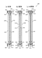
次に、吸排気ユニットを用いたダブルスキンシステムにおける吸排気制御について説明する。図2(a)は、主に冬期において実行される吸排気制御を示す側面図であり、図2(b)は、主に夏期において実行される吸排気制御を示す側面図であり、図2(c)は、主に中間期において実行される吸排気制御を示す側面図である。 Next, intake / exhaust control in the double skin system using the intake / exhaust unit will be described. 2 (a) is a side view showing intake / exhaust control executed mainly in winter, and FIG. 2 (b) is a side view showing intake / exhaust control executed mainly in summer, FIG. (C) is a side view which shows the intake / exhaust control mainly performed in an intermediate period.
図2(a)に示すように、冬期は寒いので、室外の冷たい空気は取り込まず、室内の冷たい空気を、ダブルスキン200の中間層230に送り込み、日射により中間層230で空気を暖めて、それを室内に戻すことにより、室内に温かい空気を送り込む。具体的には、まず太陽電池501によって下側の吸排気ユニット301が駆動し、太陽電池500によって上側の吸排気ユニット300も駆動しておく。
As shown in FIG. 2 (a), since it is cold in winter, the outdoor cold air is not taken in, the indoor cold air is sent to the
そして、吸排気ユニット301は内通気口411から室内の空気を取り込み、中通気口421から中間層230に空気を送り出す。日射による熱は、外ガラス210を介して室外から中間層230には入るが、内ガラス220を介して中間層230から室内には入らないので、中間層230の空気は徐々に暖められる。吸排気ユニット300は中通気口420から中間層230の空気を取り込み、内通気口410から室内に空気を送り出す。
The intake /
これにより、室内の空気を暖めることができ、暖房器具の使用を抑えることができる。すなわち、熱効率が良くなり、エネルギー効率も良くすることができる。また、既存の窓ガラスの場合、冬期であっても窓際は日射により温度が上昇し、暖房効果が加わると非常に暑くなる。しかし、温かい空気が循環すれば、窓際だけが暑くなることも防止することができる。 Thereby, indoor air can be warmed and use of a heater can be suppressed. That is, thermal efficiency can be improved and energy efficiency can be improved. Moreover, in the case of the existing window glass, even if it is winter, the temperature rises by sunlight and becomes very hot when a heating effect is added. However, if warm air circulates, it is possible to prevent only the window from becoming hot.
図2(b)に示すように、夏期は暑く、室内は冷房器具を使用しているので、室内の空気は室外に逃げないようにし、中間層230で暖められた空気は室外に排出し、中間層230には室外から別の空気を取り込む。具体的には、まず太陽電池501によって下側の吸排気ユニット301が駆動し、太陽電池500によって上側の吸排気ユニット300も駆動しておく。
As shown in FIG. 2 (b), since the summer is hot and the room uses cooling equipment, the indoor air is prevented from escaping to the outside, and the air heated by the
そして、吸排気ユニット301は外通気口401から室外の空気を取り込み、中通気口421から中間層230に空気を送り出す。日射による熱によって、中間層230の空気は徐々に暖められる。吸排気ユニット300は中通気口420から中間層230の空気を取り込み、外通気口400から室外に空気を送り出す。すなわち、中間層230の空気を循環させ、同時に熱も放出する。
The intake /
これにより、中間層230に熱が蓄積しないので、室内に熱が移行しづらく、冷房効果を維持することができる。すなわち、冷房機器の使用を抑えられるので、熱効率が良くなり、エネルギー効率も良くすることができる。また、既存の窓ガラスの場合、夏期の窓際は日射により温度が上昇し、冷房効果が弱くなる。しかし、空気が循環して熱が蓄積しなければ、窓際の温度上昇も抑えられ、冷房効果が弱くなるのを抑えることができる。
Thereby, since heat does not accumulate in the
図2(c)に示すように、春期や秋期などの中間期においては、室外の空気を室内に取り入れ、又は室内の空気を室外に送り出すなど、室内と室外の間で換気を行う。具体的には、まず太陽電池501によって下側の吸排気ユニット301が駆動し、太陽電池500によって上側の吸排気ユニット300も駆動しておく。なお、図2(c)は、室外から室内に空気を取り込む場合について、二通りの空気の流れを示している。
As shown in FIG. 2C, in the intermediate period such as spring or autumn, ventilation is performed between the room and the outside, for example, taking outdoor air into the room or sending out indoor air to the outside. Specifically, first, the lower intake /
一つ目は、中間層230を利用して、室外の空気を暖めてから室内に取り入れる場合である。吸排気ユニット301は外通気口401から室外の空気を取り込み、中通気口421から中間層230に空気を送り出す。吸排気ユニット300は中通気口420から中間層230の空気を取り込み、内通気口410から室内に空気を送り出す。
The first case is when the outdoor layer is warmed using the
二つ目は、中間層230を介さないで、室外の空気をそのまま室内に取り入れる場合である。吸排気ユニット301は外通気口401から室外の空気を取り込み、内通気口411から室内に空気を送り出す。同時に、吸排気ユニット300は外通気口400から室外の空気を取り込み、内通気口410から室内に空気を送り出す。
The second is a case where outdoor air is taken into the room as it is without passing through the
このように、ダブルスキン200において、上側の吸排気ユニット300と、下側の吸排気ユニット301を用いて、空気の流れを制御することにより、室外の環境に応じて、室内の温度を調節することができる。それにより、室内を快適な状態にするだけでなく、冷暖房器具の使用を抑えることができるので、熱効率及びエネルギー効率を向上させることができる。
In this way, in the
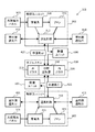
次に、吸排気ユニットを用いたダブルスキンシステムの具体的な装置構成について説明する。図3は、吸排気ユニットを用いたダブルスキンシステムの構成を示すブロック図である。ダブルスキンシステム100は、図1でも説明したように、ダブルスキン200と、上側の吸排気ユニット300と、下側の吸排気ユニット301を備える。ダブルスキン200は、外ガラス210と、内ガラス220と、その間に確保された中間層240を有し、吸排気ユニット301から排出された空気が、中間層240を上昇して、吸排気ユニット300に吸入される。
Next, a specific apparatus configuration of the double skin system using the intake / exhaust unit will be described. FIG. 3 is a block diagram showing a configuration of a double skin system using an intake / exhaust unit. As described in FIG. 1, the
図3に示すように、ダブルスキン200の上部に設置された吸排気ユニット300は、送風制御モジュール310と、ファン320と、蓄電池330とを有する。同様に、ダブルスキン200の下部に設置された吸排気ユニット301は、送風制御モジュール311と、ファン321と、蓄電池331とを有する。送風制御モジュール310、311は、風の流れを制御する機能を持つ部品であり、空気を取り込む吸気制御と、空気を送り出す排気制御の二つの機能を備える。
As shown in FIG. 3, the intake /
具体的には、送風制御モジュール311は、吸気制御として、外通気口401又は内通気口411から空気を吸入し、排気制御として、外通気口401、内通気口411、中通気口421のうち、吸入した以外のところへ排出する。中通気口421から排出された場合、空気は外ガラス210と内ガラス220の間の中間層240へ送られる。中間層240の空気は、送風制御モジュール311の排気制御、日射による温度上昇、及び送風制御モジュール310の吸気制御などによって、上方への流れが形成される。送風制御モジュール310は、吸気制御として、外通気口401、内通気口411、中通気口421のうち、いずれかから空気を吸入し、排気制御として、外通気口400又は内通気口410のうち、吸入した以外のところへ排出する。
Specifically, the
送風制御モジュール310の吸気制御及び排気制御は、ファン320を回転させることにより機能させる。同様に、送風制御モジュール311の吸気制御及び排気制御は、ファン321を回転させることにより機能させる。ファン320、321は、軸に複数の羽根を付けて、それを回転させることにより、風を発生させる送風機である。例えば、シロッコファン等があり、回転数を変えて風量を調節する。送風制御モジュール310、311において、それぞれ吸気先と排気先を指定すれば、ファン320、321を回転させることにより、吸気先から空気を取り込み、排気先へ空気を送り出す。
The air intake control and the exhaust control of the air
送風制御モジュール310及びファン320は、蓄電池330から電気を供給する。同様に、送風制御モジュール311及びファン321は、蓄電池331から電気を供給する。電動で吸排気を行うことにより、気象条件に左右されない安定した風量を得ることが可能となる。蓄電池330、331は、充電することにより繰り返し使用可能な電池である。
The air
ダブルスキン200は、主に日射の影響が大きい箇所に設置される。そのため、電気は太陽電池500で発電させるが、発電が抑制される場合もあるので、発電が可能な場合は、電気を蓄電池330に蓄積しておく。そして、送風制御モジュール310、311及びファン320、321は、消費電力も少ないことから、それらを駆動する際は、蓄電池330、331から電気を供給するようにしてもシステム構築が可能である。
The
このような構成にすることで、吸排気ユニット300、301によってダブルスキン200の窓ガラスにおける中間層240の空気の流れを制御することが可能となり、中間層240で温まった空気を室内に取り入れることや、室外に排気することができるようになる。そして、吸排気ユニット300、301を用いたダブルスキンシステム100を、建物の窓ガラスに採用することにより、建物の熱効率を向上させることができる。
With such a configuration, the air flow in the
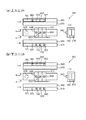
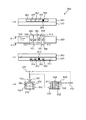
次に、本発明である吸排気ユニットについて説明する。図4は、吸排気ユニットの斜視図である。また、図5(a)は吸排気ユニットの平面図であり、図5(b)は吸排気ユニットの正面図であり、図5(c)は吸排気ユニットの左側面図である。ダブルスキン200の上部に設置する吸排気ユニット300と、下部に設置する吸排気ユニット301とは構造が同じであることから、吸排気ユニット300について説明する。
Next, the intake / exhaust unit according to the present invention will be described. FIG. 4 is a perspective view of the intake / exhaust unit. 5 (a) is a plan view of the intake / exhaust unit, FIG. 5 (b) is a front view of the intake / exhaust unit, and FIG. 5 (c) is a left side view of the intake / exhaust unit. Since the intake /
吸排気ユニット300は、図3で説明したように、送風制御モジュール310を有し、外通気口400、内通気口410、中通気口420のうち、いずれかから空気を吸入し、外通気口400、内通気口410、中通気口420のうち、吸入した以外のいずれかに空気を排出する。そのため、図4に示すように、送風制御モジュール310には、分配口340、分配口350、及び分配口360の三つの出入口が設けられる。
As described with reference to FIG. 3, the intake /
また、吸排気ユニット300は、図5(a)に示すように、ファン320を有し、風により空気の流れを発生させる。ファン320によって空気が吸引される側を、分配口340、分配口350、及び分配口360のうち、いずれかと繋ぎ、ファン320によって空気が送出される側を、分配口340、分配口350、及び分配口360のうち、吸引で繋いだ以外のいずれかと繋ぐ。
In addition, as shown in FIG. 5A, the intake /
例えば、分配口340を外通気口400と連結し、分配口350を内通気口410と連結し、分配口360を中通気口420と連結する。図5(b)に示すように、ファン320として、羽根を回転させることにより下方の空気を吸引し、遠心力を利用して側方の排気口から空気を吹き出すものを使用したとする。その場合、分配口340からファン320の下方へルートを形成し、ファン320から分配口360へルートを形成すれば、空気は外通気口400から中通気口420へ送られる。
For example, the
なお、分配口340、分配口350、及び分配口360は、直接には繋がらずに、間にファン320を介して繋がるようにする。例えば、まず、分配口340と、分配口350と、分配口360との間を区切る。その上で、図5(c)に示すように、ファン320を上側に配置したとすると、分配口340からファン320と同じ側へのルート、ファン320の下側へのルートが別々に形成されるようにする。なお、分配口350と分配口360についても同様にする。
The
分配口340、350、360の接続先である外通気口400、内通気口410、及び中通気口420が閉じた状態では、吸排気ユニット300内がほぼ密閉されたクローズ経路となるので、急な気象変化による漏水や内圧の上昇を防止することができる。すなわち、安全装置として機能する。また、吸排気ユニット300であれば、ファン320で吸排気が確保されるので、フィルターの装備も可能となる。
When the
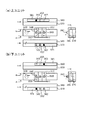
さらに、吸排気ユニット300の内部構造について説明する。図6(a)は、図5(a)に示すA線で切断した断面図であり、図6(b)は、図5(a)に示すB線で切断した断面図であり、図6(c)は、図6(a)に示すC線で切断した断面図である。また、図7(a)は、図6(b)に示すD線で切断した断面図であり、図7(b)は、図6(b)に示すE線で切断した断面図である。
Furthermore, the internal structure of the intake /
図6(a)に示すように、送風制御モジュール310内において、分配口340、分配口350、及び分配口360は、間に仕切りを設けるなどして、区分路341、区分路351、及び区分路361に区切られる。また、図6(b)に示すように、ファン320に空気が吸引されて圧力が低くなっている下段側の負圧路370と、ファン320から空気が送出されて圧力が高くなっている上段側の正圧路380とが、ファン320を境界として区切られる。
As shown in FIG. 6A, in the air
そして、図6(a)に示すように、区分路341、区分路351、及び区分路361と、負圧路370を繋ぐ手段として、吸気孔342、吸気孔352、及び吸気孔362が設けられる。図6(b)に示すように、区分路341、区分路351、及び区分路361と、正圧路380を繋ぐ手段として、排気孔343、排気孔353、及び排気孔363が設けられる。
Then, as shown in FIG. 6A, an
なお、図6(c)に示すように、区分路341、351、361は、分配口340、350、360から前面側へ回る経路と、分配口340、350、360の後面側へ回る経路とが形成される。そのため、吸気孔342、吸気孔352、及び吸気孔362は、図6(a)に示すように、区分路341、区分路351、及び区分路361の前面側であって、負圧路370と繋がる下段側に設ける。そして、排気孔343、排気孔353、及び排気孔363は、図6(b)に示すように、区分路341、区分路351、及び区分路361の後面側であって、正圧路380と繋がる上段側に設ける。
In addition, as shown in FIG.6 (c), the division paths 341,351,361 have the path | route which turns to the front side from distribution port 340,350,360, and the path | route which turns to the rear surface side of distribution port 340,350,360. Is formed. Therefore, as shown in FIG. 6A, the intake holes 342, the intake holes 352, and the intake holes 362 are on the front side of the
負圧路370の前面側には、図7(a)に示すように、シャッター371を設ける。シャッター371は、スライド可能な板材であり、開口部372が空けられる。シャッター371を横方向に移動させることで、吸気孔342、吸気孔352、吸気孔362の全てを閉口して塞ぐか、吸気孔342、吸気孔352、吸気孔362のいずれかと開口部372の位置を合わせて開口させることが可能である。
As shown in FIG. 7A, a
同様に、正圧路380の後面側には、図7(b)に示すように、シャッター381を設ける。シャッター381は、スライド可能な板材であり、開口部382が空けられる。シャッター381を横方向に移動させることで、排気孔343、排気孔353、排気孔363の全てを閉口して塞ぐか、排気孔343、排気孔353、排気孔363のいずれかと開口部382の位置を合わせて開口させることが可能である。
Similarly, a
例えば、負圧路370において、シャッター371の開口部372を吸気孔342の位置に合わせ、正圧路380において、シャッター381の開口部382を排気孔363の位置に合わせたとする。この場合、分配口340、区分路341の前面側、吸気孔342、負圧路370、ファン320、正圧路380、排気孔363、区分路361の後面側、分配口360の順に、空気の流れが形成される。
For example, assume that the
吸排気ユニット300は、その他に蓄電池330を内蔵する。蓄電池330は、太陽電池500で発生させた電気を蓄積しておき、必要に応じて、ファン320やシャッター371、381を駆動させるために電気を供給する。また、送風制御モジュール310には、シャッター371、381をスライド移動させる駆動手段や、シャッター371、381が移動する位置を登録しておく記憶手段や、シャッター371、381の移動をコントロールする制御手段なども含まれる。
In addition, the intake /
ダブルスキン構造の窓ガラスに吸排気ユニット300を設置することにより、室外と、室内と、ダブルスキン200の中間層240との間で、空気の流れを制御することができる。すなわち、室外から室内、室外から中間層240、室内から室外、室内から中間層240、中間層240から室外、中間層240から室内のいずれかに空気が流れるようにすることができる。
By installing the intake /
吸排気ユニット300は、モジュール化しているので、分配口340、350、360と、外通気口400、内通気口410、及び中通気口420とを接続する手段(例えば配管など)の連結を遮断することで、吸排気ユニット300自体を容易に取り外すことが可能である。そして、取り外した吸排気ユニット300を修理又は交換することによりメンテナンスすることができる。すなわち、吸排気ユニット300を汎用的な部品として規格化し、量産することが可能である。そのため、吸排気ユニット300の製造コストを大幅に下げることができる。
Since the intake /
次に、本発明である吸排気ユニットを用いて空気の流れを変更する方法について説明する。建物にダブルスキンシステム100が採用されている場合に、各ダブルスキン200の設定条件を選択変更するために各ダブルスキン200に変更用スイッチを設けても良いし、各部屋全部のダブルスキン200の設定条件を選択変更するために変更用リモコンを設けても良い。また、各階や建物全体のダブルスキン200の設定条件を選択変更するための変更用ボックスなどを設けても良い。
Next, a method for changing the air flow using the intake / exhaust unit according to the present invention will be described. When the
設定条件が変更されると、吸排気ユニット300、301の蓄電池330、331から送風制御モジュール310、311に電気が供給されて、負圧路370のシャッター371と、正圧路380のシャッター381とが、予め設定された位置にスライド移動し、空気を流す場合はファン320も駆動する。上側の吸排気ユニット300の設定と、下側の吸排気ユニット301の設定の組み合わせにより、ダブルスキン200における空気の流れが作られる。設定を動作モードとして登録しておくことにより、簡単な操作で自在に素早く吸排気制御を変更することが可能となる。
When the setting condition is changed, electricity is supplied from the
図8〜図13は、吸排気ユニットの動作を示す図である。なお、(a)は、上側の吸排気ユニットの動作であり、(b)は、下側の吸排気ユニットの動作である。また、各図において、中段に示す図は吸排気ユニット平面図であり、下段に示す図は平面図のA線で切断した断面図であり、上段に示す図は平面図のB線で切断した断面図であり、右側に示す図は平面図のC線で切断した断面図である。 8-13 is a figure which shows operation | movement of an intake / exhaust unit. (A) shows the operation of the upper intake / exhaust unit, and (b) shows the operation of the lower intake / exhaust unit. Moreover, in each figure, the figure shown in the middle is a plan view of the intake / exhaust unit, the figure shown in the lower is a cross-sectional view cut along line A in the plan view, and the figure shown in the upper stage is cut along line B in the plan view. It is sectional drawing and the figure shown on the right side is sectional drawing cut | disconnected by C line | wire of the top view.
図8の例は、空気の流れを制御しない設定であり、冬期の日射がない場合などに選択される。吸排気ユニット300については、負圧路370における吸気孔342、352、362のいずれもが塞がれた状態となり、正圧路380における排気孔343、353、363のいずれもが塞がれた状態となる。ファン320も駆動せず、分配口340、350、360のいずれにおいても空気の吸排気は行われない。
The example of FIG. 8 is a setting that does not control the air flow, and is selected when there is no solar radiation in winter. In the intake /
また、吸排気ユニット301については、負圧路370における吸気孔342、352、362のいずれもが塞がれた状態となり、正圧路380における排気孔343、353、363のいずれもが塞がれた状態となる。ファン320も駆動せず、分配口340、350、360のいずれにおいても空気の吸排気は行われない。
For the intake /
図9の例は、室内の空気を中間層240で暖めて室内に戻す設定であり、冬期の日射がある場合などに選択される。吸排気ユニット300については、負圧路370において吸気孔362(c)が開口し、正圧路380において排気孔353(y)が開口する。ファン320が駆動することで、分配口360(3)で吸気が行われ、分配口350(2)で排気が行われる。また、吸排気ユニット301については、負圧路370において吸気孔352(b)が開口し、正圧路380において排気孔353(y)が開口する。ファン320が駆動することで、分配口350(2)で吸気が行われ、分配口360(3)で排気が行われる。
The example of FIG. 9 is a setting in which room air is warmed by the
吸排気ユニット300、301のいずれについても、分配口340(1)は室外、分配口350(2)は室内、分配口360(3)は中間層230に繋げたとする。まず、下側の吸排気ユニット301において、室内、分配口350(2)、吸気孔352(b)、負圧路370、ファン320、正圧路380、排気孔363(z)、分配口360(3)、中間層230の順に、空気が流れる。次に、上側の吸排気ユニット300において、中間層230、分配口360(3)、吸気孔362(c)、負圧路370、ファン320、正圧路380、排気孔353(y)、分配口350(2)、室内の順に、空気が流れる。
In each of the intake /
図10の例は、中間層240で温まった空気を室外に排出して別の空気を室外から中間層240に取り入れる設定であり、夏期の日射がある場合などに選択される。吸排気ユニット300については、負圧路370において吸気孔362(c)が開口し、正圧路380において排気孔343(x)が開口する。ファン320が駆動することで、分配口360(3)で吸気が行われ、分配口354(1)で排気が行われる。また、吸排気ユニット301については、負圧路370において吸気孔342(a)が開口し、正圧路380において排気孔363(z)が開口する。ファン320が駆動することで、分配口340(1)で吸気が行われ、分配口360(3)で排気が行われる。
The example of FIG. 10 is a setting in which air warmed in the
まず、下側の吸排気ユニット301において、室外、分配口340(1)、吸気孔342(a)、負圧路370、ファン320、正圧路380、排気孔363(z)、分配口360(3)、中間層230の順に、空気が流れる。次に、上側の吸排気ユニット300において、中間層230、分配口360(3)、吸気孔362(c)、負圧路370、ファン320、正圧路380、排気孔343(x)、分配口340(1)、室外の順に、空気が流れる。
First, in the lower intake /
図11の例は、中間層240で温まった空気を室外に排出して別の空気を室内から中間層240に取り入れる設定であり、これも夏期の日射がある場合などに選択される。吸排気ユニット300については、負圧路370において吸気孔362(c)が開口し、正圧路380において排気孔343(x)が開口する。ファン320が駆動することで、分配口360(3)で吸気が行われ、分配口340(1)で排気が行われる。また、吸排気ユニット301については、負圧路370において吸気孔352(b)が開口し、正圧路380において排気孔363(z)が開口する。ファン320が駆動することで、分配口350(2)で吸気が行われ、分配口360(3)で排気が行われる。
The example of FIG. 11 is a setting in which air warmed in the
まず、下側の吸排気ユニット301において、室内、分配口350(2)、吸気孔352(b)、負圧路370、ファン320、正圧路380、排気孔363(z)、分配口360(3)、中間層230の順に、空気が流れる。次に、上側の吸排気ユニット300において、中間層230、分配口360(3)、吸気孔362(c)、負圧路370、ファン320、正圧路380、排気孔343(x)、分配口340(1)、室外の順に、空気が流れる。
First, in the lower intake /
図12の例は、室外の空気を中間層240で暖めて室内に取り入れる設定であり、中間期に換気する場合などに選択される。吸排気ユニット300については、負圧路370において吸気孔362(c)が開口し、正圧路380において排気孔353(y)が開口する。ファン320が駆動することで、分配口360(3)で吸気が行われ、分配口350(2)で排気が行われる。また、吸排気ユニット301については、負圧路370において吸気孔342(a)が開口し、正圧路380において排気孔363(z)が開口する。ファン320が駆動することで、分配口340(1)で吸気が行われ、分配口360(3)で排気が行われる。
The example of FIG. 12 is a setting in which outdoor air is warmed by the
まず、下側の吸排気ユニット301において、室外、分配口340(1)、吸気孔342(a)、負圧路370、ファン320、正圧路380、排気孔363(z)、分配口360(3)、中間層230の順に、空気が流れる。次に、上側の吸排気ユニット300において、中間層230、分配口360(3)、吸気孔362(c)、負圧路370、ファン320、正圧路380、排気孔353(y)、分配口350(2)、室内の順に、空気が流れる。
First, in the lower intake /
図13の例は、室外の空気をそのまま室内に取り入れる設定であり、これも中間期に換気する場合などに選択される。吸排気ユニット300については、負圧路370において吸気孔342(a)が開口し、正圧路380において排気孔353(y)が開口する。ファン320が駆動することで、分配口340(1)で吸気が行われ、分配口350(2)で排気が行われる。また、吸排気ユニット301については、負圧路370において吸気孔342(a)が開口し、正圧路380において排気孔353(y)が開口する。ファン320が駆動することで、分配口340(1)で吸気が行われ、分配口350(2)で排気が行われる。
The example of FIG. 13 is a setting for taking outdoor air into the room as it is, and this is also selected when ventilation is performed in an intermediate period. As for the intake /
まず、下側の吸排気ユニット301において、室外、分配口340(1)、吸気孔342(a)、負圧路370、ファン320、正圧路380、排気孔353(y)、分配口350(2)、室内の順に、空気が流れる。また、上側の吸排気ユニット300において、室外、分配口340(1)、吸気孔342(a)、負圧路370、ファン320、正圧路380、排気孔353(y)、分配口350(2)、室内の順に、空気が流れる。
First, in the lower intake /
吸排気ユニット300、301の動作パターンを予め複数設定しておき、それを選択変更することにより、ダブルスキン構造の窓ガラスを採用した建物において、熱効率及びエネルギー効率が良い状態を作り出すことができる。また、温度や湿度などをセンサーで検知し、自動的に最適な設定条件に変更することにより、常に建物内の環境を快適に維持することができる。
By setting a plurality of operation patterns of the intake /
吸排気ユニット300、301は、単純な構造で空気の流れを制御することができる。吸排気ユニット300、301を利用することで、ダブルスキン構造のカーテンウォールを簡単に構築することができる。吸排気ユニット300、301を汎用部品とすることで、設置コストも抑えることができ、メンテナンスも容易となり、熱やエネルギーを有効利用することができる等、得られる効果も大きいものとなる。
The intake /
次に、本発明である除湿吸排気ユニットを用いたダブルスキンシステムについて説明する。なお、吸排気ユニットと除湿ユニットを組み合わせたものを除湿吸排気ユニットとする。図14(a)はダブルスキンシステムを採用した窓ガラスの正面図であり、図14(b)はダブルスキンシステムを採用した窓ガラスの右側面図であり、図14(c)はダブルスキンシステムを採用した窓ガラスの平面図である。 Next, a double skin system using the dehumidifying intake / exhaust unit according to the present invention will be described. A combination of the intake / exhaust unit and the dehumidification unit is referred to as a dehumidification / exhaust unit. FIG. 14 (a) is a front view of a window glass employing a double skin system, FIG. 14 (b) is a right side view of the window glass employing a double skin system, and FIG. 14 (c) is a double skin system. It is a top view of the window glass which employ | adopted.
ダブルスキンシステム101は、建物に複数設置される窓ガラスの各々に採用される構成であり、図14(a)に示すように、少なくとも、ダブルスキン200、上側の吸排気ユニット302、及び除湿ユニット600、並びに下側の吸排気ユニット303、及び除湿ユニット601などを備える。なお、ダブルスキンシステム100と同じ構成については、説明を省略する。
The
図14に示すように、吸排気ユニット302、303は、室外と室内と中間層230の間で空気の流れを制御することに加え、中間層230と除湿ユニット600、601の間で空気の流れを制御する。吸排気ユニット302は、ダブルスキン200の上部に設置され、吸排気ユニット303は、ダブルスキン200の下部に設置されるが、吸排気ユニット302と吸排気ユニット303を連動させても良いし、それぞれ単独で動作させても良い。
As shown in FIG. 14, the intake /
除湿ユニット600、601は、吸気した空気の湿度を調整して排気する。すなわち、湿気のある空気を乾燥させたり、逆に乾燥した空気に湿気を与えたりする。除湿ユニット600、601は、吸排気ユニット302、303と組み合わせて使用する。具体的には、吸排気ユニット302、303が中間層230から空気を吸入し、除湿ユニット600、601に送出する。除湿ユニット600、601は、吸排気ユニット302、303から送られた空気の湿度を調整して中間層230に戻す。なお、除湿ユニット600、601を、除湿手段として吸排気ユニット302、303に組み込んでも良い。
The
次に、除湿吸排気ユニットを用いたダブルスキンシステムの具体的な装置構成について説明する。図15は、吸排気ユニット及び除湿ユニットを用いたダブルスキンシステムの構成を示すブロック図である。 Next, a specific apparatus configuration of a double skin system using a dehumidifying / exhausting unit will be described. FIG. 15 is a block diagram showing a configuration of a double skin system using an intake / exhaust unit and a dehumidifying unit.
図15に示すように、ダブルスキン200の上部又は下部に設置された吸排気ユニット302、303は、送風制御モジュール312、313と、ファン320、321と、蓄電池330、331とを有する。送風制御モジュール312、313は、風の流れを制御する機能を持つ部品であり、空気を取り込む吸気制御と、空気を送り出す排気制御の二つの機能を備える。
As shown in FIG. 15, the intake /
具体的には、送風制御モジュール312、313は、吸気制御として、外通気口400、401又は内通気口410、411又は中通気口420、421から空気を吸入し、排気制御として、外通気口400、401又は内通気口410、411又は中通気口420、421のうち、吸入した以外のところへ排出する。さらに、送風制御モジュール312、313は、吸気制御として、中通気口420、421から中間層240内の空気を吸入し、排気制御として、除湿ユニット600、601に空気を排出する。除湿ユニット600、601は、吸入した空気の湿度を調整して中間層240に排出する。
Specifically, the air
次に、本発明である除湿吸排気ユニットについて説明する。図16(a)は、吸排気ユニットの斜視図であり、図16(b)は、除湿ユニットの斜視図である。ダブルスキン200の上部に設置する吸排気ユニット302及び除湿ユニット600と、下部に設置する吸排気ユニット303及び除湿ユニット601とは構造が同じであることから、吸排気ユニット302及び除湿ユニット600について説明する。
Next, the dehumidification / intake / exhaust unit according to the present invention will be described. FIG. 16A is a perspective view of the intake / exhaust unit, and FIG. 16B is a perspective view of the dehumidifying unit. Since the intake /
吸排気ユニット302は、送風制御モジュール312を有し、外通気口400、内通気口410、中通気口420、除湿ユニット600のうち、いずれかから空気を吸入し、外通気口400、内通気口410、中通気口420、除湿ユニット600のうち、吸入した以外のいずれかに空気を排出する。そのため、図16(a)に示すように、送風制御モジュール312には、分配口340、分配口350、分配口360及び分配口390の四つの出入口が設けられる。
The intake /
例えば、分配口360を外通気口400と連結し、分配口350を内通気口410と連結し、分配口360を中通気口420と連結し、分配口390を除湿ユニット600と連結する。そして、分配口360からファン320の下方へルートを形成し、ファン320から分配口390へルートを形成すれば、空気は中通気口420から除湿ユニット600へ送られる。
For example, the
また、図16(b)に示すように、除湿ユニット600は、投入口610、吸気孔620、及び排気孔630等を有する。投入口610は、除湿ユニット600に除湿剤611を出し入れするための開口部である。吸気孔620は、除湿ユニット600に空気を取り込む入口であり、例えば、送風制御モジュール312の分配口390と連結する。排気孔630は、除湿ユニット600から空気を送り出す出口であり、例えば、中間層240に繋ぐ。なお、中通気孔420を介して中間層240に繋いでも良い。
Further, as shown in FIG. 16B, the
次に、本発明である除湿吸排気ユニットを用いて結露を防止する方法について説明する。建物にダブルスキンシステム101が採用されている場合に、各ダブルスキン200の設定条件を選択変更するために各ダブルスキン200に変更用スイッチを設けても良いし、各部屋全部のダブルスキン200の設定条件を選択変更するために変更用リモコンを設けても良い。また、各階や建物全体のダブルスキン200の設定条件を選択変更するための変更用ボックスなどを設けても良い。
Next, a method for preventing dew condensation using the dehumidifying and aspirating unit according to the present invention will be described. When the
設定条件が変更されると、吸排気ユニット302、303の蓄電池330、331から送風制御モジュール312、313に電気が供給されて、負圧路370のシャッター371と、正圧路380のシャッター381とが、予め設定された位置にスライド移動し、空気を流す場合はファン320も駆動する。上側の吸排気ユニット302及び除湿ユニット600の設定と、下側の吸排気ユニット303及び除湿ユニット601の設定の組み合わせにより、ダブルスキン200における除湿用の空気の流れが作られる。設定を動作モードとして登録しておくことにより、簡単な操作で自在に素早く除湿制御を変更することが可能となる。
When the setting condition is changed, electricity is supplied from the
図17は、除湿吸排気ユニットの動作を示す図である。なお、二段目に示す図は吸排気ユニット平面図であり、三段目に示す図は平面図のA線で切断した断面図であり、一段目に示す図は平面図のB線で切断した断面図であり、四段目左に示す図は平面図のC線で切断した断面図であり、四段目右に示す図は除湿ユニットの断面図である。なお、吸排気ユニット302及び除湿ユニット600と、吸排気ユニット303及び除湿ユニット601とは構造が同じであることから、吸排気ユニット302及び除湿ユニット600について説明する。また、結露を防止する場合と、除湿剤を乾燥させる場合とは、動作が同じであることから、説明が重複する部分については省略する。
FIG. 17 is a diagram illustrating the operation of the dehumidification / exhaust unit. The figure shown in the second stage is a plan view of the intake / exhaust unit, the figure shown in the third stage is a sectional view cut along the line A in the plan view, and the figure shown in the first stage is cut along the line B in the plan view. The figure shown on the left of the fourth stage is a cross-sectional view cut along line C of the plan view, and the figure shown on the right of the fourth stage is a cross-sectional view of the dehumidifying unit. Since the intake /
図17の例は、中間層240の空気の湿度を調整して結露を防止等する設定である。冬季において、中間層240の空気が外気により、湿度の高い状態で温度が下がった場合に、空気を乾燥させて結露を防止する。このとき、除湿ユニット600内の乾燥剤611は湿気を吸収する。また、中間層240の空気が日射などにより、乾燥した状態で温度が上がった場合に、空気に湿気を与える。このとき、除湿ユニット600内の乾燥剤611は湿気を奪われて乾燥する。
The example in FIG. 17 is a setting that prevents condensation by adjusting the humidity of the air in the
乾燥剤611としては、例えば、シリカゲルなどの多孔質構造で水分を吸着しやすい材料が用いられる。乾燥剤611は、水分を吸着させた状態で、熱を与えると逆に水分を放出することで、繰り返し使用することが可能なものも存在する。なお、乾燥剤611は、除湿ユニット600の投入口610から、除湿ユニット600内の網状で通気性の良いメッシュ612の中に収容される。吸気孔610から入った空気はメッシュ612内の乾燥剤611を通過して排気孔620から出ていく。
As the
吸排気ユニット302については、負圧路370において吸気孔362(c)が開口し、正圧路380において排気孔393(z)が開口する。ファン320が駆動することで、分配口360(3)で吸気が行われ、分配口390(4)で排気が行われる。吸排気ユニット302において、分配口340(1)は室外、分配口350(2)は室内、分配口360(3)は中間層230、分配口390(4)は除湿ユニット600に繋げたとする。
As for the intake /
吸排気ユニット302において、中間層230、分配口360(3)、区分路361、吸気孔362(c)、負圧路370、ファン320、正圧路380、排気孔393(z)、区分路391、分配口390(4)、除湿ユニット600の順に空気が流れる。また、除湿ユニット600において、吸気孔620、除湿剤611、排気孔630、中間層230の順に空気が流れる。なお、負圧路370において吸気孔392(d)を開口させ、正圧路380において排気孔363(y)が開口させることにより、中間層230、除湿ユニット600、吸排気ユニット302、中間層230の順に空気が流れるようにしても良い。
In the intake /
次に、本発明である除湿吸排気ユニットを用いたダブルスキンシステムの効果について説明する。まず、ダブルスキンシステム101を採用した店舗(ショールーム等)の例を示す。ダブルスキンシステム101は、内ガラス220に広告などを掲載し、必要に応じて内ガラス220を収納できる構造とする。内ガラス220は、高断熱遮熱性能を持つ複層ガラスユニットとし、外ガラス210は、一般的な単板ガラスとする。
Next, the effect of the double skin system using the dehumidification / exhaust unit according to the present invention will be described. First, an example of a store (showroom or the like) employing the
冬季において、内ガラス220を収納し、外ガラス210のみで使用する。店舗内は、暖房空調(例えば、設定温度20度、湿度40%)で運転する。内ガラス220を外ガラス210の内側に配置し、ダブルスキン構造にする。内ガラス220と外ガラス210の間の中間層230には、温度と湿度を持った空気が密閉される。ここで、外気温が低下したとする。中間層230の外ガラス側の温度は、外気温の低下に伴い低下していき、露点温度(例えば、6度)に達した時点で結露が発生する。
In winter, the
除湿ユニット600については、幅1.5メートル、高さ3.5メートル、奥行き0.3メートルの1.575立方メートルの容積とする。想定する中間層230内の空気の温度は20度、相対湿度は100%とする。除湿剤611として使用するシリカゲルは、粒の大きさが0.5〜0.9ミリメートルであり、重さが1リットルあたり740グラム、重量の20%まで水分を吸収できるものとする。すなわち、除湿剤611を100グラム使用したとき、水分を20グラム吸収することができる。
The
温度が20度で相対湿度が100%の空気が持つ水蒸気量は、1立方メートルあたり17.23グラムであるので、中間層230内の空気が持つ水蒸気量は、1.575×17.23=27.14グラムとなる。シリカゲルの必要重量は、27.14/0.2=135.7グラムとなり、シリカゲルの必要体積は、135.7/740=0.183リットルとなる。
Since the amount of water vapor in air having a temperature of 20 degrees and a relative humidity of 100% is 17.23 grams per cubic meter, the amount of water vapor in the air in the
また、シリカゲルのうち、B型シリカゲルを使用した場合、相対温度に対して吸湿率が変化する。低湿度環境下では吸湿量は少なく、高湿度環境下では吸湿率が高くなる。シリカゲルが吸湿し、中間層230内の湿度が低下し、シリカゲルの吸湿力が低下していくと、シリカゲルの吸湿量が相対湿度に対するシリカゲルの吸湿力に近い状態になる。除湿ユニット600の使用後は、この湿度で均衡することになる。
Moreover, when B type silica gel is used among silica gels, a moisture absorption rate changes with respect to relative temperature. The amount of moisture absorption is small in a low humidity environment, and the moisture absorption rate is high in a high humidity environment. When the silica gel absorbs moisture, the humidity in the
除湿ユニット600を使用していない初期状態においては、中間層230の温度を20度、湿度を50%、水分量を13.6グラムとすると、露点温度は9.3度であった。除湿剤611として100gのシリカゲルを使用した場合、湿度が32%に下がって、水分量が8.7グラム、シリカゲルの吸湿量が4.9グラムとなり、露点が2.8度に下がった。除湿剤611として200gのシリカゲルを使用した場合、湿度が28%に下がって、水分量が7.6グラム、シリカゲルの吸湿量が6.0グラムとなり、露点が1.0度に下がった。除湿剤611として300gのシリカゲルを使用した場合、湿度が20.3%に下がって、水分量が5.5グラム、シリカゲルの吸湿量が9.1グラムとなり、露点が−3.6度に下がった。
In an initial state where the
これらの結果を基に、中間層230内の温度が、そのときの中間層230の湿度における露点温度以下とならないように制御することにより、結露を効果的に防止することができる。除湿ユニット600などに温度及び湿度を検出するセンサー等を設けることにより、警告により操作を促しても良いし、自動的に制御することも可能となる。
(変形例)
Based on these results, it is possible to effectively prevent dew condensation by controlling the temperature in the
(Modification)
以上、本発明の実施例を述べたが、これらに限定されるものではない。例えば、ダブルスキン200に吸排気ユニット300、301を備えたダブルスキンシステム100の窓ガラスを建物に設置するだけでなく、既存の一枚の板ガラスからなる窓ガラスの室内側に内ガラスを設置する、又は室外側に外ガラスを設置することにより、ダブルスキン構造にし、吸排気ユニット300、301を設置してダブルスキンシステム100を構築しても良い。
As mentioned above, although the Example of this invention was described, it is not limited to these. For example, not only the window glass of the
また、ダブルスキン200は、外ガラス210を板ガラス、内ガラス220を複層ガラスの組み合わせだけでなく、外ガラス210と内ガラス220を同じ板ガラスにしても良いし、外ガラス210と内ガラス220を同じ複層ガラスにしても良いし、外ガラス210を複層ガラス、内ガラス220を板ガラスの組み合わせにしても良い。
In addition, the
さらに、吸排気ユニット300、301は、空気を吸排気することができれば、上側の吸排気ユニット300だけにしても良いし、下側の吸排気ユニット301だけにしても良い。また、図3においては、吸排気ユニット301、中間層230、吸排気ユニット300の空気の流れだけでなく、吸排気ユニット300、中間層230、吸排気ユニット301の逆の流れで制御しても良い。なお、吸排気ユニット300と吸排気ユニット301とは、同じ装置にしなければならない訳ではなく、吸排気ユニット300と吸排気ユニット301とで同様の機能を発揮できれば別の装置であっても良い。
Further, the intake /
吸排気ユニット300の分配口340、350、360は、いずれか一つが吸入側、吸入側になった以外のいずれか一つが排出側に接続されるが、残った一つについても吸入側又は排出側に接続されるように設計しても良い。なお、シャッター371の開口部372の数、又はシャッター381の開口部382の数を増やすことにより、空気の流れを分散させれば良い。
Any one of the
ダブルスキン200において、吸排気ユニット300、301をサッシ枠内に設置して、ダブルスキン200と交換可能な吸排気ユニット300、301とをまとめて扱うようにしても良いが、吸排気ユニット300、301を天井や床下に設置して、ダブルスキン200と交換可能な吸排気ユニット300、301とを別々に扱えるようにしても良い。ダブルスキン200とシングルスキンとを容易に変更することも可能となる。
In the
100,101:ダブルスキンシステム
200:ダブルスキン
210:外ガラス
220:内ガラス
230:中間層
240:ブラインド
300,301,302,303:吸排気ユニット
310,311,312,313:送風制御モジュール
320,321:ファン
330,331:蓄電池
340,350,360,390:分配口
341,351,361,391:区分路
342,352,362,392:吸気孔
343,353,363,393:排気孔
370:負圧路
371:シャッター
372:開口部
380:正圧路
381:シャッター
382:開口部
400,401:外通気口
410,411:内通気口
420,421:中通気口
500,501:太陽電池
600,601:除湿ユニット
610:投入口
611:除湿剤
612:メッシュ
620:吸気孔
630:排気孔
100, 101: Double skin system 200: Double skin 210: Outer glass 220: Inner glass 230: Intermediate layer 240:
Claims (5)
前記第1の分配口とは区分けされた空気が出入りする第2の分配口と、
前記第1及び2の分配口とは区分けされた空気が出入りする第3の分配口と、
前記第1、2及び3の分配口とは区分けされた空気が出入りする第4の分配口と、
吸引した空気を送出するファンと、
前記ファンによって空気が吸引される側であって、前記第1、2、3又は4の分配口と繋がる吸気孔が空けられた負圧路と、
前記ファンによって空気が排出される側であって、前記第1、2、3又は4の分配口と繋がる排気孔が空けられた正圧路と、
排出された空気の湿度を調整する除湿手段と、を備え、
前記第1、2、3又は4のうち何れかの分配口から空気を吸引し、前記第1、2、3又は4のうち前記吸引している以外の何れかの分配口へ空気を送出し、
前記第1、2、3又は4のうち何れかの分配口から送出された場合に、空気の湿度を前記除湿手段で調整した上で送出する、
ことを特徴とする除湿吸排気ユニット。 A first distribution port through which air enters and exits;
A second distribution port through which air separated from the first distribution port enters and exits;
A third distribution port through which air separated from the first and second distribution ports enters and exits;
A fourth distribution port through which air separated from the first, second, and third distribution ports enters and exits;
A fan that sends out the sucked air;
A negative pressure path on the side where air is sucked by the fan and having an intake hole connected to the first, second, third, or fourth distribution port;
A positive pressure path on the side from which air is discharged by the fan and having an exhaust hole connected to the first, second, third or fourth distribution port;
Dehumidifying means for adjusting the humidity of the discharged air,
Air is sucked from one of the first, second, third and fourth distribution ports, and air is sent to one of the first, second, third and fourth distribution ports other than the suction port. ,
When it is sent out from any one of the first, second, third, or fourth distribution ports, it is sent out after adjusting the humidity of the air with the dehumidifying means.
A dehumidifying intake / exhaust unit characterized by that.
ことを特徴とする請求項1に記載の除湿吸排気ユニット。 A battery for accumulating electricity generated by a solar cell and supplying electricity to the fan;
The dehumidification / exhaust unit according to claim 1.
前記正圧路は、複数の排気孔をシャッターで開口又は閉口することによって前記第1、2、3又は4の分配口と繋げられる、
ことを特徴とする請求項1又は2に記載の除湿吸排気ユニット。 The negative pressure path is connected to the first, second, third, or fourth distribution port by opening or closing a plurality of intake holes with a shutter,
The positive pressure path is connected to the first, second, third or fourth distribution port by opening or closing a plurality of exhaust holes with a shutter.
The dehumidification intake / exhaust unit according to claim 1 or 2.
室外側に配される外ガラスと、室内側に配される内ガラスと、前記外ガラスと前記内ガラスの間の中間層とからなるダブルスキン構造の窓ガラスの上部と下部に設置し、
前記吸排気ユニットが、前記前記室外側と前記室内側と前記中間層の間で空気の吸排気を行う、
ことを特徴とするダブルスキンシステム。 The dehumidifying intake / exhaust unit according to any one of claims 1 to 3,
Installed on the upper and lower parts of the double-skin window glass consisting of an outer glass arranged on the outdoor side, an inner glass arranged on the indoor side, and an intermediate layer between the outer glass and the inner glass,
The intake / exhaust unit performs air intake / exhaust between the outdoor side, the indoor side, and the intermediate layer;
This is a double skin system.
前記下部の吸排気ユニットが、前記室外側又は前記室内側から吸入した空気を前記中間層に排出し、
前記上部の吸排気ユニットが、前記中間層から吸入した空気を前記室外側又は前記室内側に排出する、
ことを特徴とする除湿吸排気方法。 The double skin system according to claim 4,
The lower intake / exhaust unit discharges the air sucked from the outdoor side or the indoor side to the intermediate layer,
The upper intake / exhaust unit discharges the air sucked from the intermediate layer to the outdoor side or the indoor side,
A dehumidifying / exhausting method characterized by that.
Priority Applications (1)
| Application Number | Priority Date | Filing Date | Title |
|---|---|---|---|
| JP2015126592A JP6414781B2 (en) | 2015-06-24 | 2015-06-24 | Dehumidification intake / exhaust unit, double skin system, and dehumidification intake / exhaust method |
Applications Claiming Priority (1)
| Application Number | Priority Date | Filing Date | Title |
|---|---|---|---|
| JP2015126592A JP6414781B2 (en) | 2015-06-24 | 2015-06-24 | Dehumidification intake / exhaust unit, double skin system, and dehumidification intake / exhaust method |
Publications (2)
| Publication Number | Publication Date |
|---|---|
| JP2017009221A true JP2017009221A (en) | 2017-01-12 |
| JP6414781B2 JP6414781B2 (en) | 2018-10-31 |
Family
ID=57763185
Family Applications (1)
| Application Number | Title | Priority Date | Filing Date |
|---|---|---|---|
| JP2015126592A Active JP6414781B2 (en) | 2015-06-24 | 2015-06-24 | Dehumidification intake / exhaust unit, double skin system, and dehumidification intake / exhaust method |
Country Status (1)
| Country | Link |
|---|---|
| JP (1) | JP6414781B2 (en) |
Cited By (1)
| Publication number | Priority date | Publication date | Assignee | Title |
|---|---|---|---|---|
| CN108193994A (en) * | 2017-12-27 | 2018-06-22 | 山东大学 | A kind of multi-functional double-layer glass vent window |
Citations (9)
| Publication number | Priority date | Publication date | Assignee | Title |
|---|---|---|---|---|
| JPS59173644A (en) * | 1983-03-22 | 1984-10-01 | Nippon Light Metal Co Ltd | Air exhauster employed on window for reducing air conditioning energy consumption |
| JPS63251591A (en) * | 1987-04-07 | 1988-10-19 | 西武電機工業株式会社 | Sash building in ventilating device |
| JP2000088309A (en) * | 1998-09-14 | 2000-03-31 | Kajima Corp | Ventilating equipment used for both air supply and exhaust |
| JP2005240278A (en) * | 2004-02-24 | 2005-09-08 | Oiles Eco Corp | Ventilating direction control device, ventilating mechanism equipped with the same, and building |
| JP2007100437A (en) * | 2005-10-06 | 2007-04-19 | Ohbayashi Corp | Double window ventilation system |
| JP2013221277A (en) * | 2012-04-13 | 2013-10-28 | Takenaka Komuten Co Ltd | Natural ventilation system using double skin |
| JP2014142118A (en) * | 2013-01-23 | 2014-08-07 | Taisei Corp | Dehumidification air conditioning system |
| WO2014121801A2 (en) * | 2013-02-08 | 2014-08-14 | Climawin Techniq Aps | Window comprising a modular drum valve |
| JP2016180533A (en) * | 2015-03-24 | 2016-10-13 | 株式会社デバイス | Intake/exhaust unit and double skin system using the same |
-
2015
- 2015-06-24 JP JP2015126592A patent/JP6414781B2/en active Active
Patent Citations (9)
| Publication number | Priority date | Publication date | Assignee | Title |
|---|---|---|---|---|
| JPS59173644A (en) * | 1983-03-22 | 1984-10-01 | Nippon Light Metal Co Ltd | Air exhauster employed on window for reducing air conditioning energy consumption |
| JPS63251591A (en) * | 1987-04-07 | 1988-10-19 | 西武電機工業株式会社 | Sash building in ventilating device |
| JP2000088309A (en) * | 1998-09-14 | 2000-03-31 | Kajima Corp | Ventilating equipment used for both air supply and exhaust |
| JP2005240278A (en) * | 2004-02-24 | 2005-09-08 | Oiles Eco Corp | Ventilating direction control device, ventilating mechanism equipped with the same, and building |
| JP2007100437A (en) * | 2005-10-06 | 2007-04-19 | Ohbayashi Corp | Double window ventilation system |
| JP2013221277A (en) * | 2012-04-13 | 2013-10-28 | Takenaka Komuten Co Ltd | Natural ventilation system using double skin |
| JP2014142118A (en) * | 2013-01-23 | 2014-08-07 | Taisei Corp | Dehumidification air conditioning system |
| WO2014121801A2 (en) * | 2013-02-08 | 2014-08-14 | Climawin Techniq Aps | Window comprising a modular drum valve |
| JP2016180533A (en) * | 2015-03-24 | 2016-10-13 | 株式会社デバイス | Intake/exhaust unit and double skin system using the same |
Cited By (1)
| Publication number | Priority date | Publication date | Assignee | Title |
|---|---|---|---|---|
| CN108193994A (en) * | 2017-12-27 | 2018-06-22 | 山东大学 | A kind of multi-functional double-layer glass vent window |
Also Published As
| Publication number | Publication date |
|---|---|
| JP6414781B2 (en) | 2018-10-31 |
Similar Documents
| Publication | Publication Date | Title |
|---|---|---|
| JP5842194B1 (en) | Intake / exhaust unit and double skin system using the same | |
| JP5870450B2 (en) | Double skin curtain wall and air conditioning system | |
| CN104181950B (en) | Electric power outdoor cabinet temperature control system and its control method | |
| JP2014508872A (en) | Window shutter unit for external building | |
| KR101672838B1 (en) | Energy Saving Building Circulation System | |
| JP2007100437A (en) | Double window ventilation system | |
| JP6414781B2 (en) | Dehumidification intake / exhaust unit, double skin system, and dehumidification intake / exhaust method | |
| JP4853127B2 (en) | Heat exchange ventilator | |
| JP5757260B2 (en) | Double skin structure | |
| JP3944181B2 (en) | Building air conditioning system | |
| JP2018123999A (en) | Wind passage selector damper, fan coil unit and air conditioning system | |
| WO2023109102A1 (en) | Intelligent environment control machine | |
| CN204753916U (en) | Energy -conserving curtain of double -deck type of respiration of inner loop | |
| KR20190007139A (en) | Prefabricated Ventilation Apparatus Conducting dual Duct | |
| CN104374006B (en) | A kind of air regulator | |
| JP2020070965A (en) | Heat exchange type ventilating device | |
| JP7018862B2 (en) | Double skin structure, air conditioning system and how to operate the air conditioning system | |
| KR20120137984A (en) | Green ventilation system | |
| KR20060025617A (en) | A windows and doors have the faculty of automatic ventilation | |
| KR100577208B1 (en) | ventilating system | |
| CN104963435A (en) | Internal-circulation double-layer respiration type energy-saving curtain wall | |
| JP6486290B2 (en) | Ventilation system | |
| KR20190108744A (en) | Indoor ventilation apparatus for building | |
| CN215710954U (en) | Novel elevator machine room ventilation system | |
| JP4541372B2 (en) | Pneumatic solar collector ventilation system |
Legal Events
| Date | Code | Title | Description |
|---|---|---|---|
| A621 | Written request for application examination |
Free format text: JAPANESE INTERMEDIATE CODE: A621 Effective date: 20170906 |
|
| A521 | Request for written amendment filed |
Free format text: JAPANESE INTERMEDIATE CODE: A821 Effective date: 20170906 |
|
| A977 | Report on retrieval |
Free format text: JAPANESE INTERMEDIATE CODE: A971007 Effective date: 20180620 |
|
| A131 | Notification of reasons for refusal |
Free format text: JAPANESE INTERMEDIATE CODE: A131 Effective date: 20180626 |
|
| A521 | Request for written amendment filed |
Free format text: JAPANESE INTERMEDIATE CODE: A523 Effective date: 20180730 |
|
| TRDD | Decision of grant or rejection written | ||
| A01 | Written decision to grant a patent or to grant a registration (utility model) |
Free format text: JAPANESE INTERMEDIATE CODE: A01 Effective date: 20180904 |
|
| A61 | First payment of annual fees (during grant procedure) |
Free format text: JAPANESE INTERMEDIATE CODE: A61 Effective date: 20180921 |
|
| R150 | Certificate of patent or registration of utility model |
Ref document number: 6414781 Country of ref document: JP Free format text: JAPANESE INTERMEDIATE CODE: R150 |
|
| R250 | Receipt of annual fees |
Free format text: JAPANESE INTERMEDIATE CODE: R250 |
|
| R250 | Receipt of annual fees |
Free format text: JAPANESE INTERMEDIATE CODE: R250 |