JP2017008808A - Blow-by gas recirculation device - Google Patents
Blow-by gas recirculation device Download PDFInfo
- Publication number
- JP2017008808A JP2017008808A JP2015124996A JP2015124996A JP2017008808A JP 2017008808 A JP2017008808 A JP 2017008808A JP 2015124996 A JP2015124996 A JP 2015124996A JP 2015124996 A JP2015124996 A JP 2015124996A JP 2017008808 A JP2017008808 A JP 2017008808A
- Authority
- JP
- Japan
- Prior art keywords
- blow
- gas
- gas pipe
- pipe
- scraper
- Prior art date
- Legal status (The legal status is an assumption and is not a legal conclusion. Google has not performed a legal analysis and makes no representation as to the accuracy of the status listed.)
- Pending
Links
Images


Abstract
Description
本発明は、内燃機関のクランクケース内に漏出したブローバイガスを通流させて同内燃機関の吸気通路に還流させるブローバイガス還流装置に関する。 The present invention relates to a blow-by gas recirculation device that causes a blow-by gas leaked into a crankcase of an internal combustion engine to flow and recirculate to the intake passage of the internal combustion engine.
従来から、内燃機関のクランクケース内に漏出するブローバイガスを吸気系統(吸気通路)に還流させるためのブローバイガス還流装置が普及している。ブローバイガスは、未燃燃料(HC)に加えて多量の水分を含んでいる。そのため、内燃機関が低温環境下(例えば、−20℃程度以下)において使用される場合、吸気通路近傍領域のブローバイガス管においてその水分が凍結しブローバイガス管の内壁面に霜及び/又は氷として付着することが知られている。霜及び/又は氷がブローバイガス管の内壁面に付着し続けると、ブローバイガス管の通流が妨げられブローバイガス管が閉塞し、その結果、ブローバイガスを適正に還流できない虞がある。 Conventionally, blow-by gas recirculation devices for recirculating blow-by gas leaking into a crankcase of an internal combustion engine to an intake system (intake passage) have become widespread. Blow-by gas contains a large amount of moisture in addition to unburned fuel (HC). Therefore, when the internal combustion engine is used in a low-temperature environment (for example, about −20 ° C. or less), the moisture is frozen in the blow-by gas pipe in the vicinity of the intake passage, and is formed as frost and / or ice on the inner wall surface of the blow-by gas pipe. It is known to adhere. If frost and / or ice continue to adhere to the inner wall surface of the blow-by gas pipe, the flow of the blow-by gas pipe is hindered and the blow-by gas pipe is blocked, and as a result, the blow-by gas may not be properly circulated.
そこで、従来のブローバイガス還流装置の一つ(以下、「従来装置」と称呼する。)は、ブローバイガス管の途中にサーミスタを有する銅板を備える。サーミスタは銅板の温度を計測する。銅板にはブローバイガスの通流が可能となるように貫通部が設けられている。従来装置は、銅板の温度(サーミスタの温度)が規定の温度を下回ると銅板を加熱するための加熱電流を流すようになっている。よって、従来装置は、ブローバイガス管を通流するブローバイガスを銅板によって加熱することにより、銅板の下流における結露又は凍結を防止するようになっている(例えば、特許文献1を参照。)。 Therefore, one of the conventional blow-by gas recirculation devices (hereinafter referred to as “conventional device”) includes a copper plate having a thermistor in the middle of the blow-by gas pipe. The thermistor measures the temperature of the copper plate. The copper plate is provided with a through portion so that blow-by gas can flow. In the conventional apparatus, when the temperature of the copper plate (the temperature of the thermistor) falls below a specified temperature, a heating current for heating the copper plate is passed. Therefore, the conventional apparatus prevents the condensation or freezing downstream of the copper plate by heating the blow-by gas flowing through the blow-by gas pipe with the copper plate (see, for example, Patent Document 1).
しかしながら、従来装置は、銅板をヒータとして使用しているので電力を消費する。特に、使用環境が低温であるほど電力の消費量が大きくなるという問題がある。 However, the conventional apparatus consumes electric power because the copper plate is used as a heater. In particular, there is a problem that power consumption increases as the usage environment is lower.
本発明は上記問題に対処するために為されたものである。即ち、本発明の目的の一つは、電力を消費することなく、ブローバイガス通路の内壁面に付着した霜及び/又は氷を取り除くことができる装置を提供することにある。 The present invention has been made to address the above problems. That is, one of the objects of the present invention is to provide an apparatus capable of removing frost and / or ice attached to the inner wall surface of a blow-by gas passage without consuming electric power.
本発明のブローバイガス還流装置(以下、「本発明装置」と称呼する。)は、ブローバイガス管と、バネ部材と、スクレイパと、を備える。 The blow-by gas recirculation device of the present invention (hereinafter referred to as “the device of the present invention”) includes a blow-by gas pipe, a spring member, and a scraper.
前記ブローバイガス管は、内燃機関のクランクケース内に漏出したブローバイガスを通流させて同内燃機関の吸気通路に還流させるように同吸気通路を構成する部材に接続される。 The blow-by gas pipe is connected to a member constituting the intake passage so that the blow-by gas leaked into the crankcase of the internal combustion engine flows and is returned to the intake passage of the internal combustion engine.
前記バネ部材は、前記ブローバイガス管の内部において前記ブローバイガスの通流方向に沿って伸縮可能となるように、その一部が前記ブローバイガス管に支持される。 A part of the spring member is supported by the blow-by gas pipe so that the spring member can expand and contract in the flow direction of the blow-by gas inside the blow-by gas pipe.
前記スクレイパは、前記バネ部材の他部に支持され、且つ、前記ブローバイガス管の振動によって前記バネ部材が伸縮したときに同ブローバイガス管の内部において往復移動することにより、前記ブローバイガス管と前記吸気通路を構成する部材との接続部の近傍領域内の前記ブローバイガスが通流する通路の内壁面に付着した霜及び/又は氷を掻き落とす。 The scraper is supported by the other part of the spring member, and reciprocates inside the blow-by gas pipe when the spring member expands and contracts due to vibration of the blow-by gas pipe, so that the blow-by gas pipe and the scraper The frost and / or ice adhering to the inner wall surface of the passage through which the blow-by gas flows in the vicinity of the connection portion with the member constituting the intake passage is scraped off.
ブローバイガス管(例えば、PCV(Positive Crankcase Ventilation)ホース)は、内燃機関の運転時に発生する振動によって、或いは同機関を搭載する車両の走行時の振動によって振動する。更に、ブローバイガス管の振動に伴い、ブローバイガス管にその一部が支持されたバネ部材がブローバイガス管の内部において伸縮する。結果として、バネ部材の他部に支持されたスクレイパがブローバイガス管内を移動(往復移動)する。 A blow-by gas pipe (for example, PCV (Positive Crankcase Ventilation) hose) vibrates due to vibration generated during operation of the internal combustion engine or vibration during travel of a vehicle equipped with the engine. Further, as the blow-by gas pipe is vibrated, the spring member partially supported by the blow-by gas pipe expands and contracts inside the blow-by gas pipe. As a result, the scraper supported by the other part of the spring member moves (reciprocates) in the blow-by gas pipe.
このとき、スクレイパはこの霜及び/又は氷を掻き落とす。従って、本発明装置によれば、加熱装置を用いることなく(即ち、電力を消費することなく)、ブローバイガスが通流する通路の内壁面に発生する霜及び/又は氷を除去することができる。 At this time, the scraper scrapes off the frost and / or ice. Therefore, according to the apparatus of the present invention, it is possible to remove frost and / or ice generated on the inner wall surface of the passage through which blow-by gas flows without using a heating device (that is, without consuming electric power). .
以下、図面を参照しながら本発明の実施形態に係るブローバイガス還流装置(以下、「本還流装置」と称呼する。)について説明する。 Hereinafter, a blowby gas recirculation apparatus (hereinafter referred to as “the present recirculation apparatus”) according to an embodiment of the present invention will be described with reference to the drawings.
(構成)
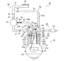
本還流装置は、図1に示した内燃機関10に適用される。機関10は、火花点火式の4サイクル・ピストン往復動型・直列4気筒・ガソリン内燃機関である。機関10は、機関本体部20、吸気系統30及び排気系統40を含んでいる。
(Constitution)
The present reflux device is applied to the
機関本体部20は、クランクケース21、クランクシャフト22、シリンダブロック23、ピストン23c、コネクティングロッド23e、シリンダヘッド24、吸気弁25、排気弁26、燃料噴射弁27及び点火装置28を含んでいる。
The
クランクケース21は、クランクシャフト22を回転可能に支持している。以下、クランクケース21は、オイルパンOPとともに、クランクケース室21aを構成している。
The
シリンダブロック23は、クランクケース21の上方においてクランクケース21に固定されている。シリンダブロック23は、アルミニウム製であって、中空円筒状のシリンダ(シリンダボア)23aを複数個(4気筒分、即ち4つ)備えている。シリンダ23aの内周には鋳鉄製のシリンダライナ23bが嵌入されている。
The
シリンダ23aにはピストン23cが収容されている。ピストン23cは略円筒形であり、側面に複数のピストンリング23dを備えている。ピストン23cは、コネクティングロッド23eによってクランクシャフト22に連結されている。ピストン23cの上面(頂面)はシリンダライナ23bの内壁面及びシリンダヘッド24の下面とともに燃焼室CCを形成している。
A
シリンダヘッド24は、シリンダブロック23の上方においてシリンダブロック23に固定されている。シリンダヘッド24には、燃焼室CCに連通する吸気ポートIP及び燃焼室CCに連通する排気ポートEPが形成されている。吸気ポートIPは吸気弁25により開閉される。排気ポートEPは排気弁26により開閉される。シリンダヘッド24はシリンダヘッドカバー24cにより覆われている。シリンダヘッド24内には、燃料噴射弁27及び点火装置28が備えられている。
The
機関10の吸気行程において、吸気弁25が開弁すると、燃料噴射弁27から噴射された燃料と吸気との混合気が吸気ポートIPから燃焼室CCに導入される。その後、圧縮行程にて点火装置28により混合気が点火され混合気が爆発したとき、ピストンリング23dとシリンダライナ23bとの間に間隙があると、未燃燃料を含む燃焼ガスがその間隙からクランクケース室21aに漏出する。この漏出ガスは「ブローバイガス」と称呼されている。ブローバイガスには、未燃燃料の他に多量の水分が含まれている。
When the
吸気系統30は、吸気管31、エアフィルタ32、スロットルバルブ33及びサージタンク34を含んでいる。
The intake system 30 includes an
吸気管31は、吸気ポートIPと接続されている。従って、吸気管31、サージタンク34及び吸気ポートIPは吸気通路を構成している。吸気管31は、「吸気通路を構成する部材」である。スロットルバルブ33は、機関10へ供給される吸気の量を調整するために設けられている。吸気は図1の矢印A1の向きに通流する。
The
サージタンク34は、吸気管31の途中に設けられている。サージタンク34は、「吸気通路を構成する部材」である。スロットルバルブ33の開度が比較的低いとき(例えば、車両の減速時及びアイドリング時)、サージタンク34内の圧力はスロットルバルブ33よりも上流側の吸気管31における圧力よりも低くなる。このような状態は「吸気負圧」状態と称呼される。
The
排気系統40は、排気管41及び触媒装置42を含んでいる。排気管41は排気ポートEPと接続されている。従って、排気管41及び排気ポートEPは排気通路を構成している。
The
ブローバイガス還流装置50は、第1ガス通路部51、第2ガス通路部52、第3ガス通路部53、PCVバルブ54、第4ガス通路部55、コイルバネ(バネ部材)56及びスクレイパ57を含む。
The blow-by
第1ガス通路部51は、機関10本体の外部に設けられたガス管51aによって構成されている。第1ガス通路部51の一端はシリンダヘッドカバー24cに接続されている。第1ガス通路部51の他端はスロットルバルブ33よりも吸気上流側の吸気管31に接続されている。
The first
第2ガス通路部52はシリンダヘッド24内に形成されている。従って、第2ガス通路部52は、第1ガス通路部51を通して吸気管31のスロットルバルブ33よりも吸気上流側と連通されている。更に、第2ガス通路部52は、シリンダヘッド24内の所定の経路を通り、PCVバルブ54に接続されている。
The second
第3ガス通路部53はシリンダブロック23内に形成されている。第3ガス通路部53はシリンダヘッド24内の第2ガス通路部52とクランクケース室21aとを連通している。
The third
PCVバルブ54は、逆止弁型のバルブであり、シリンダヘッド24の開口部に取り付けられている。PCVバルブ54は、シリンダヘッド24内(クランクケース室21a)の圧力がサージタンク34内の圧力よりも高いときに開弁する。PCVバルブ54は、シリンダヘッド24内の圧力とサージタンク34内の圧力の差が過度に大きい場合にはその開度を小さくし、PCVバルブ54を通過するブローバイガスの量を制限することができるようになっている。
The
第4ガス通路部55は、機関10本体の外部に設けられたブローバイガス管55aにより構成されている。ブローバイガス管55aは、「PCVホース」とも称呼される。第4ガス通路部55の一端はPCVバルブ54の吐出部に接続され、他端はスロットルバルブ33よりも吸気下流側のサージタンク34に接続されている。ブローバイガス管(PCVホース)55aのサージタンク34との接続部CN近傍の内壁面には、スクレイパ57を備えたコイルバネ56の一端が支持されている。以下、スクレイパ57を備えたコイルバネ56を「霜掻き取り部」とも称呼する。
The fourth
なお、第1ガス通路部51及び/又は第4ガス通路部55には、ブローバイガスに含まれるオイルミスト及び煤等を分離除去するオイルキャッチタンクが設けられてもよい。
The
以上の構成において、サージタンク34内に吸気負圧(以下、単に「負圧」とも称呼する。)が発生している場合には、シリンダヘッド24内の圧力は、サージタンク34内の圧力より高くなっている。よって、この場合、PCVバルブ54が開弁する。このとき、燃焼室CCからクランクケース室21aに漏出したブローバイガスは、図1の矢印A2の向きに従って第2ガス通路部52、第3ガス通路部53、PCVバルブ54及び第4ガス通路部55を通ってサージタンク34(吸気系統30)へと還流(流入)させられる。これと同時に、クランクケース室21aには、図1の矢印A3に示したように、第1ガス通路部51、第2ガス通路部52及び第3ガス通路部53を通って吸気が流れ込む。
In the above configuration, when intake negative pressure (hereinafter also simply referred to as “negative pressure”) is generated in the
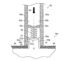
次に、図2を参照しながら、第4ガス通路部55の「霜掻き取り部」の構造を説明する。図2には、第4ガス通路部55を構成するブローバイガス管55aと、サージタンク34と、の接続部CN及びその近傍の断面図が示される。
Next, the structure of the “frost scraping portion” of the fourth
ブローバイガス管55aは、サージタンク34の壁に嵌挿された円筒状の接続用管材(所謂「ユニオン」)35を介してサージタンク34に接続される。具体的には、接続用管材35の外壁面35aにブローバイガス管55aの内壁面55bが当接するように接続用管材35がブローバイガス管55aに挿入されている。ブローバイガス管55aの内壁面55bの一部にはブローバイガス管55aの内周に沿って環状の突起部55cが設けられている。
The blow-
コイルバネ56は、ブローバイガス管55aの内部においてブローバイガスの通流方向に沿って伸縮可能となるように、その一端が突起部55c(ブローバイガス管55a)に支持される。即ち、コイルバネ56は、コイルバネ56の軸線方向Cとブローバイガスの通流方向が平行となるように支持される。コイルバネ56の外径は、突起部55cの内径と略等しい。
One end of the
コイルバネ56の他端(即ち、突起部55cに固定されていない側の端部)にはスクレイパ57が固定されている。スクレイパ57は、略円板状の形状を有している。スクレイパ57は樹脂でできている。スクレイパ57の外径は、接続用管材35の内径よりも小さい。スクレイパ57の外周部57aの厚さはスクレイパ57の中心から径方向外方へ向かうほど小さくなっており、スクレイパ57の外周部57aは、その最外周部分が尖った「ブレード形状」を有している。スクレイパ57の中心部には、ブローバイガスの通流を妨げないように貫通孔57bが設けられている。後で詳述するように、スクレイパ57は、ブローバイガス管55aの振動によってコイルバネ56が伸縮したときにブローバイガス管55aの内部において往復移動する。
A
図2において、ブローバイガスの通流方向は矢印A2にて示されるように、紙面の上から下に向かう方向である。 In FIG. 2, the flow direction of blow-by gas is the direction from the top to the bottom of the page, as indicated by arrow A2.
(霜及び/又は氷の付着)
以上のように構成された第4ガス通路部55における「霜掻き取り部」の作用について説明する前に、図1及び図5(「霜掻き取り部」がない場合)を参照しながら第4ガス通路部55及び接続用管材35において霜及び/又は氷が付着する様子について説明する。
(Frost and / or ice adhesion)
Before describing the operation of the “frost scraping portion” in the fourth
サージタンク34内の圧力がクランクケース室21aの圧力よりも低い場合、図1に示したPCVバルブ54が開弁する。PCVバルブ54を通った未燃成分及び水分を含むブローバイガスは、第4ガス通路部55を通り、第4ガス通路部55とサージタンク34との接続部CN(接続用管材35)において、サージタンク34を通流する吸気と合流する。
When the pressure in the
サージタンク34内の吸気ガスの温度は機関10を搭載した車両の外気温と同等である。よって、クランクケース室21aから排出された比較的高温のブローバイガスは接続部CNにおいて吸気ガスによって冷却される。特に、低温下(例えば、−20℃程度以下)においてブローバイガスが低温の吸気によって冷却されると、ブローバイガスに含まれる水分(水蒸気)は急激に冷却されて凍結し霜及び/又は氷となる。以下、「霜及び/又は氷」は単に「霜」とも称呼される。図5に示したように霜FRは第4ガス通路部55の内壁面55b、接続用管材35の内壁面35bに付着する。
The temperature of the intake gas in the
(作用)
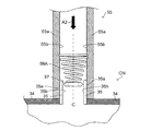
次に、図3を参照しながら「霜掻き取り部」の「霜掻き取り」の作用について説明する。
(Function)
Next, the operation of “frost scraping” of the “frost scraper” will be described with reference to FIG.
機関10はその運転中にクランクシャフト21aの回転運動及びピストン23dの往復運動等により機械的に振動している。よって、機関10(のシリンダヘッド24)と接続している第4ガス通路部55も機関10とともに振動する。例えば、機関10の回転速度NEが700〜6000rpmの間で変化する場合、上記機械的振動の固有振動周波数は11.7〜100Hzの間で変化する。
During operation, the
コイルバネ56の一端は、第4ガス通路部55の突起部55cに固定されている。よって、機関10が振動するとコイルバネ56の一端が機関10の振動の変位(第4ガス通路部55の変位)に応じて変位する。コイルバネ56の他端(スクレイパ57が固定されている側)は、コイルバネ56の一端と同様の変位を受けるとともに、コイルバネ56及びスクレイパ57の重量と加速度との積による力とコイルバネ56の伸縮の程度に応じた力とが作用する。スクレイパ57はコイルバネ56により拘束されているので、スクレイパ57は、コイルバネ56の「復元しようとする力」によって第4ガス通路部55に対しブローバイガスの通流方向に相対的に変位(単振動)する。
One end of the
以上のように、スクレイパ57は機関10の振動等により第4ガス通路部55内を往復動し、機関10の振動周波数と「霜掻き取り部」の振動周波数とが一致するときには、スクレイパ57は大きく変位する。この際、図3に示したように、スクレイパ57は第4ガス通路部55の内壁面55b又は接続用管材35の内壁面35bに付着した霜FRをブレード部57aによって掻き取りながら往復動する。従って、本還流装置は、第4ガス通路部55及び接続用管材35内が霜FRによって閉塞されることを防ぐことができる。
As described above, the
本発明は上記実施形態に限定されることはなく、本発明の範囲内において種々の変形例を採用することができる。 The present invention is not limited to the above embodiment, and various modifications can be employed within the scope of the present invention.
(変形例)
コイルバネの形状は、図4に示したように円錐型であってもよい。この場合、突起部55cを設ける必要がないか、或いは、突起部の高さ55cの高さ(第4ガス通路部55の半径方向における突起部の長さ)を低くすることができる。従って、この場合、ブローバイガスの通流の妨げとなる要素を減少させることができる。
(Modification)
The shape of the coil spring may be conical as shown in FIG. In this case, it is not necessary to provide the
なお、本還流装置が適用される機関は、他の形式の機関(例えば、ディーゼル機関)であってもよい。 It should be noted that the engine to which the present reflux device is applied may be another type of engine (for example, a diesel engine).
説明したスクレイパ57は樹脂製であるが、スクレイパは金属及び硬質のゴムであってもよい。スクレイパの形状は図2に示す形状に限ることはなく、第4ガス通路部55の内壁面55bに付着した霜を掻き落とすことが可能な形状、例えば、単なる円板形状であってもよい。更に、スクレイパは、その外周にブラシ毛を備えたものであってもよい。
The
10…内燃機関(機関)、21…クランクケース、30…吸気系統、31…吸気管、33…スロットルバルブ、34…サージタンク、35…接続用管材、35b…接続用管材内壁面、54…PCVバルブ、55…第4ガス通路部、55a…ブローバイガス管、55b…ブローバイガス管内壁面、55c…突起部、56…コイルバネ、57…スクレイパ。
DESCRIPTION OF
Claims (1)
前記ブローバイガス管の内部において前記ブローバイガスの通流方向に沿って伸縮可能となるように、その一部が前記ブローバイガス管に支持されるバネ部材と、
前記バネ部材の他部に支持され、且つ、前記ブローバイガス管の振動によって前記バネ部材が伸縮したときに同ブローバイガス管の内部において往復移動することにより、前記ブローバイガス管と前記吸気通路を構成する部材との接続部の近傍領域内の前記ブローバイガスが通流する通路の内壁面に付着した霜及び/又は氷を掻き落とすスクレイパと、
を備えるブローバイガス還流装置。
In a blow-by gas recirculation device comprising a blow-by gas pipe connected to a member constituting the intake passage so that the blow-by gas leaked into the crankcase of the internal combustion engine flows and recirculates to the intake passage of the internal combustion engine.
A spring member partially supported by the blow-by gas pipe so as to be able to expand and contract along the flow direction of the blow-by gas inside the blow-by gas pipe;
The blow-by gas pipe and the intake passage are configured by reciprocating in the blow-by gas pipe when the spring member is supported by the other part of the spring member and the spring member expands and contracts due to vibration of the blow-by gas pipe. A scraper that scrapes off frost and / or ice adhering to the inner wall surface of the passage through which the blow-by gas flows in a region in the vicinity of the connection portion with the member to be
A blow-by gas recirculation apparatus comprising:
Priority Applications (1)
| Application Number | Priority Date | Filing Date | Title |
|---|---|---|---|
| JP2015124996A JP2017008808A (en) | 2015-06-22 | 2015-06-22 | Blow-by gas recirculation device |
Applications Claiming Priority (1)
| Application Number | Priority Date | Filing Date | Title |
|---|---|---|---|
| JP2015124996A JP2017008808A (en) | 2015-06-22 | 2015-06-22 | Blow-by gas recirculation device |
Publications (1)
| Publication Number | Publication Date |
|---|---|
| JP2017008808A true JP2017008808A (en) | 2017-01-12 |
Family
ID=57761844
Family Applications (1)
| Application Number | Title | Priority Date | Filing Date |
|---|---|---|---|
| JP2015124996A Pending JP2017008808A (en) | 2015-06-22 | 2015-06-22 | Blow-by gas recirculation device |
Country Status (1)
| Country | Link |
|---|---|
| JP (1) | JP2017008808A (en) |
Cited By (4)
| Publication number | Priority date | Publication date | Assignee | Title |
|---|---|---|---|---|
| CN107461132A (en) * | 2017-08-30 | 2017-12-12 | 贵州省智能崛起科技有限公司 | A kind of defroster and Defrost method for rolling screen door |
| US10399316B2 (en) | 2006-05-19 | 2019-09-03 | Massachusetts Institute Of Technology | Nanostructure-reinforced composite articles and methods |
| JP2020006850A (en) * | 2018-07-10 | 2020-01-16 | 株式会社Subaru | Steam discharge device |
| WO2024069672A1 (en) * | 2022-09-26 | 2024-04-04 | 株式会社Subaru | Blowby gas processing device |
-
2015
- 2015-06-22 JP JP2015124996A patent/JP2017008808A/en active Pending
Cited By (6)
| Publication number | Priority date | Publication date | Assignee | Title |
|---|---|---|---|---|
| US10399316B2 (en) | 2006-05-19 | 2019-09-03 | Massachusetts Institute Of Technology | Nanostructure-reinforced composite articles and methods |
| CN107461132A (en) * | 2017-08-30 | 2017-12-12 | 贵州省智能崛起科技有限公司 | A kind of defroster and Defrost method for rolling screen door |
| CN107461132B (en) * | 2017-08-30 | 2019-03-05 | 贵州省智能崛起科技有限公司 | A kind of defroster and Defrost method for rolling screen door |
| JP2020006850A (en) * | 2018-07-10 | 2020-01-16 | 株式会社Subaru | Steam discharge device |
| JP7132674B2 (en) | 2018-07-10 | 2022-09-07 | 株式会社Subaru | steam exhaust |
| WO2024069672A1 (en) * | 2022-09-26 | 2024-04-04 | 株式会社Subaru | Blowby gas processing device |
Similar Documents
| Publication | Publication Date | Title |
|---|---|---|
| JP2017008808A (en) | Blow-by gas recirculation device | |
| JP5974886B2 (en) | Turbocharger | |
| DK178468B1 (en) | A top piston ring for a large two-stroke turbo-charged uniflow-scavenged internal combustion engine with crossheads | |
| JP5983350B2 (en) | PCV valve mounting structure | |
| JP2010511124A5 (en) | ||
| JP4946856B2 (en) | Oil separator | |
| RU2528227C1 (en) | Ice design | |
| JP2008038839A (en) | Dry sump engine | |
| KR100551288B1 (en) | Crankcase having blowby gas passage and oil drain passage | |
| JP6875871B2 (en) | Blow-by gas device | |
| JP6526523B2 (en) | Cylinder block | |
| JP2007297975A (en) | Piston unit for internal combustion engine and ring groove structure for piston | |
| JP6015843B2 (en) | Cooling device for a supercharger of an internal combustion engine equipped with a blow-by gas recirculation device | |
| KR102507235B1 (en) | Device for ice protecting blow-by gas | |
| US11236670B2 (en) | Internal combustion engine with two working spaces of a cylinder | |
| JP2013133717A (en) | Ignition plug cooling structure of auxiliary-chamber type spark-ignition internal combustion engine | |
| US20170350286A1 (en) | Integrated pcv oil separator and oil fill tube | |
| JP5161138B2 (en) | Internal combustion engine with breather device | |
| JP6006175B2 (en) | Blowby gas recirculation system | |
| JP5704091B2 (en) | Variable compression ratio internal combustion engine | |
| JP2010037993A (en) | Internal combustion engine | |
| JP2014020303A (en) | Piston and piston ring for internal combustion engine | |
| JP2021156198A (en) | Blow-by gas recirculation device | |
| JP2020051371A (en) | Structure of oil dropping passage of internal combustion engine | |
| JP2011241879A (en) | Piston ring |