JP2017008501A - Work machine - Google Patents

Work machine Download PDF

Info

Publication number
JP2017008501A
JP2017008501A JP2015122306A JP2015122306A JP2017008501A JP 2017008501 A JP2017008501 A JP 2017008501A JP 2015122306 A JP2015122306 A JP 2015122306A JP 2015122306 A JP2015122306 A JP 2015122306A JP 2017008501 A JP2017008501 A JP 2017008501A
Authority
JP
Japan
Prior art keywords
pressure
valve
unit
stop
pilot pressure
Prior art date
Legal status (The legal status is an assumption and is not a legal conclusion. Google has not performed a legal analysis and makes no representation as to the accuracy of the status listed.)
Granted
Application number
JP2015122306A
Other languages
Japanese (ja)
Other versions
JP2017008501A5 (en
JP6619163B2 (en
Inventor
麻里子 水落
Mariko Mizuochi
麻里子 水落
啓範 石井
Keihan Ishii
啓範 石井
和吉 花川
Wakichi Hanakawa
和吉 花川
Current Assignee (The listed assignees may be inaccurate. Google has not performed a legal analysis and makes no representation or warranty as to the accuracy of the list.)
Hitachi Construction Machinery Co Ltd
Original Assignee
Hitachi Construction Machinery Co Ltd
Priority date (The priority date is an assumption and is not a legal conclusion. Google has not performed a legal analysis and makes no representation as to the accuracy of the date listed.)
Filing date
Publication date
Application filed by Hitachi Construction Machinery Co Ltd filed Critical Hitachi Construction Machinery Co Ltd
Priority to JP2015122306A priority Critical patent/JP6619163B2/en
Priority to CN201610101989.4A priority patent/CN106256966B/en
Priority to KR1020160021711A priority patent/KR101814657B1/en
Priority to US15/183,132 priority patent/US10024032B2/en
Priority to EP16174832.2A priority patent/EP3106572B1/en
Publication of JP2017008501A publication Critical patent/JP2017008501A/en
Publication of JP2017008501A5 publication Critical patent/JP2017008501A5/ja
Application granted granted Critical
Publication of JP6619163B2 publication Critical patent/JP6619163B2/en
Active legal-status Critical Current
Anticipated expiration legal-status Critical

Links

Images

Classifications

    • EFIXED CONSTRUCTIONS
    • E02HYDRAULIC ENGINEERING; FOUNDATIONS; SOIL SHIFTING
    • E02FDREDGING; SOIL-SHIFTING
    • E02F3/00Dredgers; Soil-shifting machines
    • E02F3/04Dredgers; Soil-shifting machines mechanically-driven
    • E02F3/28Dredgers; Soil-shifting machines mechanically-driven with digging tools mounted on a dipper- or bucket-arm, i.e. there is either one arm or a pair of arms, e.g. dippers, buckets
    • E02F3/36Component parts
    • E02F3/42Drives for dippers, buckets, dipper-arms or bucket-arms
    • EFIXED CONSTRUCTIONS
    • E02HYDRAULIC ENGINEERING; FOUNDATIONS; SOIL SHIFTING
    • E02FDREDGING; SOIL-SHIFTING
    • E02F9/00Component parts of dredgers or soil-shifting machines, not restricted to one of the kinds covered by groups E02F3/00 - E02F7/00
    • E02F9/20Drives; Control devices
    • E02F9/22Hydraulic or pneumatic drives
    • E02F9/2221Control of flow rate; Load sensing arrangements
    • E02F9/2225Control of flow rate; Load sensing arrangements using pressure-compensating valves
    • E02F9/2228Control of flow rate; Load sensing arrangements using pressure-compensating valves including an electronic controller
    • EFIXED CONSTRUCTIONS
    • E02HYDRAULIC ENGINEERING; FOUNDATIONS; SOIL SHIFTING
    • E02FDREDGING; SOIL-SHIFTING
    • E02F3/00Dredgers; Soil-shifting machines
    • E02F3/04Dredgers; Soil-shifting machines mechanically-driven
    • E02F3/28Dredgers; Soil-shifting machines mechanically-driven with digging tools mounted on a dipper- or bucket-arm, i.e. there is either one arm or a pair of arms, e.g. dippers, buckets
    • E02F3/30Dredgers; Soil-shifting machines mechanically-driven with digging tools mounted on a dipper- or bucket-arm, i.e. there is either one arm or a pair of arms, e.g. dippers, buckets with a dipper-arm pivoted on a cantilever beam, i.e. boom
    • E02F3/32Dredgers; Soil-shifting machines mechanically-driven with digging tools mounted on a dipper- or bucket-arm, i.e. there is either one arm or a pair of arms, e.g. dippers, buckets with a dipper-arm pivoted on a cantilever beam, i.e. boom working downwardly and towards the machine, e.g. with backhoes
    • EFIXED CONSTRUCTIONS
    • E02HYDRAULIC ENGINEERING; FOUNDATIONS; SOIL SHIFTING
    • E02FDREDGING; SOIL-SHIFTING
    • E02F9/00Component parts of dredgers or soil-shifting machines, not restricted to one of the kinds covered by groups E02F3/00 - E02F7/00
    • E02F9/20Drives; Control devices
    • E02F9/22Hydraulic or pneumatic drives
    • E02F9/2203Arrangements for controlling the attitude of actuators, e.g. speed, floating function
    • E02F9/2207Arrangements for controlling the attitude of actuators, e.g. speed, floating function for reducing or compensating oscillations
    • EFIXED CONSTRUCTIONS
    • E02HYDRAULIC ENGINEERING; FOUNDATIONS; SOIL SHIFTING
    • E02FDREDGING; SOIL-SHIFTING
    • E02F9/00Component parts of dredgers or soil-shifting machines, not restricted to one of the kinds covered by groups E02F3/00 - E02F7/00
    • E02F9/20Drives; Control devices
    • E02F9/22Hydraulic or pneumatic drives
    • E02F9/2253Controlling the travelling speed of vehicles, e.g. adjusting travelling speed according to implement loads, control of hydrostatic transmission
    • EFIXED CONSTRUCTIONS
    • E02HYDRAULIC ENGINEERING; FOUNDATIONS; SOIL SHIFTING
    • E02FDREDGING; SOIL-SHIFTING
    • E02F9/00Component parts of dredgers or soil-shifting machines, not restricted to one of the kinds covered by groups E02F3/00 - E02F7/00
    • E02F9/20Drives; Control devices
    • E02F9/22Hydraulic or pneumatic drives
    • E02F9/2264Arrangements or adaptations of elements for hydraulic drives
    • E02F9/2267Valves or distributors
    • EFIXED CONSTRUCTIONS
    • E02HYDRAULIC ENGINEERING; FOUNDATIONS; SOIL SHIFTING
    • E02FDREDGING; SOIL-SHIFTING
    • E02F9/00Component parts of dredgers or soil-shifting machines, not restricted to one of the kinds covered by groups E02F3/00 - E02F7/00
    • E02F9/20Drives; Control devices
    • E02F9/22Hydraulic or pneumatic drives
    • E02F9/2264Arrangements or adaptations of elements for hydraulic drives
    • E02F9/2271Actuators and supports therefor and protection therefor
    • EFIXED CONSTRUCTIONS
    • E02HYDRAULIC ENGINEERING; FOUNDATIONS; SOIL SHIFTING
    • E02FDREDGING; SOIL-SHIFTING
    • E02F9/00Component parts of dredgers or soil-shifting machines, not restricted to one of the kinds covered by groups E02F3/00 - E02F7/00
    • E02F9/20Drives; Control devices
    • E02F9/22Hydraulic or pneumatic drives
    • E02F9/2278Hydraulic circuits
    • E02F9/2285Pilot-operated systems
    • EFIXED CONSTRUCTIONS
    • E02HYDRAULIC ENGINEERING; FOUNDATIONS; SOIL SHIFTING
    • E02FDREDGING; SOIL-SHIFTING
    • E02F9/00Component parts of dredgers or soil-shifting machines, not restricted to one of the kinds covered by groups E02F3/00 - E02F7/00
    • E02F9/26Indicating devices
    • E02F9/267Diagnosing or detecting failure of vehicles
    • E02F9/268Diagnosing or detecting failure of vehicles with failure correction follow-up actions
    • FMECHANICAL ENGINEERING; LIGHTING; HEATING; WEAPONS; BLASTING
    • F15FLUID-PRESSURE ACTUATORS; HYDRAULICS OR PNEUMATICS IN GENERAL
    • F15BSYSTEMS ACTING BY MEANS OF FLUIDS IN GENERAL; FLUID-PRESSURE ACTUATORS, e.g. SERVOMOTORS; DETAILS OF FLUID-PRESSURE SYSTEMS, NOT OTHERWISE PROVIDED FOR
    • F15B11/00Servomotor systems without provision for follow-up action; Circuits therefor
    • F15B11/16Servomotor systems without provision for follow-up action; Circuits therefor with two or more servomotors
    • FMECHANICAL ENGINEERING; LIGHTING; HEATING; WEAPONS; BLASTING
    • F15FLUID-PRESSURE ACTUATORS; HYDRAULICS OR PNEUMATICS IN GENERAL
    • F15BSYSTEMS ACTING BY MEANS OF FLUIDS IN GENERAL; FLUID-PRESSURE ACTUATORS, e.g. SERVOMOTORS; DETAILS OF FLUID-PRESSURE SYSTEMS, NOT OTHERWISE PROVIDED FOR
    • F15B13/00Details of servomotor systems ; Valves for servomotor systems
    • F15B13/02Fluid distribution or supply devices characterised by their adaptation to the control of servomotors
    • F15B13/06Fluid distribution or supply devices characterised by their adaptation to the control of servomotors for use with two or more servomotors
    • EFIXED CONSTRUCTIONS
    • E02HYDRAULIC ENGINEERING; FOUNDATIONS; SOIL SHIFTING
    • E02FDREDGING; SOIL-SHIFTING
    • E02F3/00Dredgers; Soil-shifting machines
    • E02F3/04Dredgers; Soil-shifting machines mechanically-driven
    • E02F3/96Dredgers; Soil-shifting machines mechanically-driven with arrangements for alternate or simultaneous use of different digging elements
    • E02F3/963Arrangements on backhoes for alternate use of different tools
    • E02F3/964Arrangements on backhoes for alternate use of different tools of several tools mounted on one machine
    • FMECHANICAL ENGINEERING; LIGHTING; HEATING; WEAPONS; BLASTING
    • F15FLUID-PRESSURE ACTUATORS; HYDRAULICS OR PNEUMATICS IN GENERAL
    • F15BSYSTEMS ACTING BY MEANS OF FLUIDS IN GENERAL; FLUID-PRESSURE ACTUATORS, e.g. SERVOMOTORS; DETAILS OF FLUID-PRESSURE SYSTEMS, NOT OTHERWISE PROVIDED FOR
    • F15B2211/00Circuits for servomotor systems
    • F15B2211/50Pressure control
    • F15B2211/575Pilot pressure control

Abstract

PROBLEM TO BE SOLVED: To provide a work machine having improved operationality and stability by actualizing operation restriction required for keeping the work machine stable in such a configuration as to maintain conventional operationality.SOLUTION: The work machine includes: a stabilizing control computing part 60a for computing and outputting a gentle stop command to gently stop a driving actuator according to the stable condition of the work machine and a working speed restriction command to restrict an upper limit working speed; a stop characteristic changing part 210 for correcting a pilot pressure so as to gently stop the driving actuator during stopping operation of an operation lever; and a working speed restricting part 240 for correcting the pilot pressure so as to restrict the working speed of the driving actuator. When the gentle stop command and the working speed restriction command are input from the stabilizing control computing part 60a, the pilot pressure to be output from a proportional pressure reducing valve is corrected, and when the gentle stop command and the working speed restriction command are not input, the pilot pressure to be output from the proportional pressure reducing valve is supplied to a flow control valve without being corrected.SELECTED DRAWING: Figure 3

Description

本発明は、構造物解体工事、廃棄物処理、スクラップ処理、道路工事、建設工事、土木工事等に使用される作業機械に関する。   The present invention relates to a work machine used for structure dismantling work, waste processing, scrap processing, road construction, construction work, civil engineering work, and the like.

構造物解体工事、廃棄物処理、スクラップ処理、道路工事、建設工事、土木工事等に使用される作業機械として、動力系により走行する走行体の上部に旋回体を旋回自在に取り付けると共に、旋回体に多関節型の作業フロントを上下方向に揺動自在に取り付け、作業フロントを構成する各フロント部材をアクチュエータにて駆動する作業機械が知られている。このような作業機械の一例として、油圧ショベルをベースとし、一端が旋回体に揺動自在に連結されたブームと、一端がブームの先端に揺動自在に連結されたアームと、アームの先端に装着されたグラップル、バケット、ブレーカ、クラッシャ等のアタッチメントを備え、所望の作業を行えるようにした作業機械がある。   As a work machine used for structure demolition work, waste disposal, scrap processing, road construction, construction work, civil engineering work, etc., a revolving body is attached to the upper part of a traveling body that is driven by a power system, and the revolving body There is known a work machine in which an articulated work front is attached so as to be swingable in the vertical direction and each front member constituting the work front is driven by an actuator. As an example of such a working machine, a hydraulic excavator is used as a base, one end of the boom is swingably connected to the swing body, one end of the boom is swingably connected to the tip of the boom, and the arm has a tip. There is a work machine provided with attachments such as attached grapples, buckets, breakers, and crushers so that a desired work can be performed.

この種の作業機械は、作業フロントを構成するブーム、アームおよびアタッチメントを旋回体の外方に突き出した状態で種々姿勢を変えながら作業を行う。このため、過度の作業負荷をかける、過負荷かつフロントを伸ばした状態で急動作を行う等の無理な操作を行った場合に作業機械がバランスを崩すことがある。したがって、この種の作業機械については、従来種々の転倒防止技術が提案されている。   This type of work machine performs work while changing various postures in a state where a boom, an arm, and an attachment constituting the work front are projected outward from the revolving structure. For this reason, when an unreasonable operation such as applying an excessive work load or performing an abrupt operation with an overload and the front extended, the work machine may lose its balance. Therefore, various fall prevention techniques have been proposed for this type of work machine.

例えば、特許文献1には、作業機械のブームおよびアームにそれぞれ角度センサを設け、これら各角度センサの検出信号を制御装置に入力し、制御装置が、前記検出信号に基づいて作業機械全体の重心位置と、走行体の接地面における安定支点の支持力を演算し、その演算結果に基づく安定支点における支持力値を表示装置に表示すると共に、後方安定支点における支持力が安全作業確保上の限界値以下になったときには警報を発するようにした技術が開示されている。   For example, in Patent Document 1, angle sensors are provided for the boom and the arm of the work machine, and detection signals from these angle sensors are input to the control device. The position and the supporting force of the stable fulcrum on the ground contact surface of the traveling body are calculated, the supporting force value at the stable fulcrum based on the calculation result is displayed on the display device, and the supporting force at the rear stable fulcrum is the limit for ensuring safety work. A technique is disclosed in which an alarm is issued when the value falls below the value.

一方、前述の解体作業機械のような作業機械は、大質量の走行体、旋回体および作業フロントを駆動することにより作業を行うので、何らかの理由により操作者が動作中の走行体、旋回体又は作業フロントの駆動を急停止させる操作を行った場合、作業機械に大きな慣性力が作用し、安定性に大きな影響を与える。特に、搭載された警報装置から転倒の可能性を通知する警報が発せられた場合に、操作者が慌てて動作中の走行体、旋回体又は作業フロントの駆動を停止させる操作を行うと、転倒方向に大きな慣性力が重畳されて、却って転倒の可能性が高まる虞がある。   On the other hand, a work machine such as the above-described dismantling work machine performs work by driving a mass traveling body, a revolving body, and a work front. When an operation for suddenly stopping the driving of the work front is performed, a large inertial force acts on the work machine, greatly affecting the stability. In particular, when an alarm is issued from the installed alarm device to notify the possibility of a fall, if the operator rushes and stops driving the running body, turning body or work front, There is a possibility that a large inertial force is superimposed on the direction, and the possibility of falling is increased.

このような課題に対しては、特許文献2において、作業フロントを含む本体および走行体の各可動部の位置情報と急停止モデルとを用いて、操作レバーが操作状態から瞬時に停止指令状態に戻された場合の作業機械が完全に停止に至るまでの安定性変化を予測し、停止に至るまでのいずれの時刻においても不安定にならないように駆動アクチュエータの動作制限を行う制御技術が開示されている。   For such a problem, in Patent Document 2, using the position information of each movable part of the main body and the traveling body including the work front and the sudden stop model, the operation lever is instantaneously changed from the operation state to the stop command state. Disclosed is a control technology that predicts the stability change until the work machine is completely stopped when it is returned, and restricts the operation of the drive actuator so that it does not become unstable at any time until it stops. ing.

特許第2871105号公報Japanese Patent No. 2871105 国際公開第2012/169531号International Publication No. 2012/169531

作業機械に対して特許文献2に示される技術を適用することによって、無理な操作や操作ミスにより急に動作を停止させる場合であっても、作業機械が転倒することを未然に回避し、安定に作業を継続させることができる。特許文献2に示される技術は、制御演算結果に基づいて、作業機械の駆動アクチュエータの動作を制限する技術である。   By applying the technique disclosed in Patent Document 2 to the work machine, even if the operation is suddenly stopped due to an unreasonable operation or an operation error, the work machine can be prevented from tipping over and stable. The work can be continued. The technique disclosed in Patent Document 2 is a technique that restricts the operation of a drive actuator of a work machine based on a control calculation result.

一般に、作業機械の駆動アクチュエータは、駆動アクチュエータへの圧油の供給を制御するパイロット式流量制御弁と操作レバーの操作に基づいて流量制御弁にパイロット圧油を出力する比例減圧弁とを備えて構成される油圧パイロット式駆動油圧回路によって駆動制御される。   Generally, a drive actuator of a work machine includes a pilot-type flow control valve that controls supply of pressure oil to the drive actuator and a proportional pressure-reduction valve that outputs pilot pressure oil to the flow control valve based on operation of an operation lever. The drive is controlled by a hydraulic pilot drive hydraulic circuit that is configured.

このような作業機械に特許文献2に示される技術を適用し、駆動アクチュエータに対して動作制限を行うためには、制御演算結果に応じてアクチュエータへの圧油の供給を変更する制御手段を駆動油圧回路に組み込む必要がある。しかしながら、従来例では、油圧パイロット式駆動油圧回路を備えた作業機械において、動作制限を実現するための構成が示されていない。また、駆動油圧回路に制御手段を組み込む際に、駆動油圧回路の構成を大幅に変更すると、応答性等が変化し、従来の操作性が損なわれる恐れがある。   In order to apply the technique disclosed in Patent Document 2 to such a work machine and restrict the operation of the drive actuator, the control means that changes the supply of pressure oil to the actuator according to the control calculation result is driven. Must be built into the hydraulic circuit. However, in the conventional example, a configuration for realizing operation restriction is not shown in a work machine including a hydraulic pilot drive hydraulic circuit. In addition, when the control means is incorporated in the drive hydraulic circuit, if the configuration of the drive hydraulic circuit is significantly changed, the responsiveness and the like may change, and the conventional operability may be impaired.

本発明は、上記の課題を解決するためになされたものであり、作業機械を安定に保つために必要な動作制限を従来の操作性を維持可能な構成で実現し、操作性および安定性の高い作業機械を提供することを目的とする。   The present invention has been made in order to solve the above-described problems, and realizes the operation restriction necessary for keeping the work machine stable with a configuration capable of maintaining the conventional operability. The purpose is to provide a high working machine.

上記課題を解決するために、例えば特許請求の範囲に記載の構成を採用する。
本発明は、上記課題を解決する手段を複数含んでいるが、その一例を挙げるならば、作業機械本体と、この作業機械本体に対して上下方向に揺動自在に取り付けられ複数の可動部を有する作業フロントと、この作業フロントの各可動部を駆動する駆動アクチュエータと、この駆動アクチュエータの駆動を制御する制御演算を行う演算装置と、前記駆動アクチュエータへの圧油の供給を制御する流量制御弁および操作レバーの操作に基づいて前記流量制御弁に供給するパイロット圧油を出力する比例減圧弁を有するアクチュエータ駆動油圧回路とを備えた作業機械において、前記演算装置は、作業機械の速度を推定する速度推定部と、前記速度推定部によって推定された速度と作業機械の姿勢に基づき、作業機械が急停止すると仮定した場合の作業機械の挙動を予測する急停止時挙動予測部と、前記急停止時挙動予測部によって予測された挙動に基づき前記作業機械の安定性を判定する安定性判定部と、前記安定性判定部の判定結果に基づき前記駆動アクチュエータの減速度を制限して前記駆動アクチュエータを緩やかに停止させる緩停止指令および前記駆動アクチュエータの上限動作速度を制限する動作速度制限指令を演算し、出力する動作制限決定部とを有し、前記アクチュエータ駆動油圧回路は、前記動作制限決定部からの前記緩停止指令および前記動作速度制限指令に応じて前記比例減圧弁から出力されるパイロット圧を補正するパイロット圧補正部を有し、このパイロット圧補正部は、前記操作レバーの停止操作時に前記駆動アクチュエータを緩やかに停止させるようにパイロット圧を補正する停止特性変更部と、前記駆動アクチュエータの動作速度を制限するようにパイロット圧を補正する動作速度制限部とから構成され、前記停止特性変更部および前記動作速度制限部は、前記動作制限決定部からの前記緩停止指令および前記動作速度制限指令によってそれぞれ駆動され、前記動作制限決定部から前記緩停止指令および前記動作速度制限指令が入力された場合は前記比例減圧弁から出力されるパイロット圧を補正し、前記動作制限決定部から前記緩停止指令および前記動作速度制限指令が入力されない場合には、前記比例減圧弁から出力されるパイロット圧を補正することなく前記流量制御弁に供給することを特徴とする。
In order to solve the above problems, for example, the configuration described in the claims is adopted.
The present invention includes a plurality of means for solving the above-described problems. For example, a work machine main body and a plurality of movable parts attached to the work machine main body so as to be swingable in the vertical direction are provided. A work front, a drive actuator for driving each movable part of the work front, an arithmetic device for performing a control operation for controlling the drive of the drive actuator, and a flow rate control valve for controlling the supply of pressure oil to the drive actuator And an actuator drive hydraulic circuit having a proportional pressure reducing valve that outputs pilot pressure oil supplied to the flow rate control valve based on operation of the operation lever, wherein the arithmetic unit estimates the speed of the work machine Based on the speed estimation unit and the speed estimated by the speed estimation unit and the posture of the work machine, it is assumed that the work machine is suddenly stopped An emergency stop behavior prediction unit that predicts the behavior of the industrial machine, a stability determination unit that determines the stability of the work machine based on the behavior predicted by the sudden stop behavior prediction unit, and the stability determination unit An operation restriction determination unit that calculates and outputs a slow stop command for restricting the deceleration of the drive actuator based on the determination result to gently stop the drive actuator and an operation speed restriction command for restricting the upper limit operation speed of the drive actuator. The actuator drive hydraulic circuit includes a pilot pressure correction unit that corrects a pilot pressure output from the proportional pressure reducing valve in response to the slow stop command and the operation speed limit command from the operation limit determination unit. And the pilot pressure correction unit is configured to stop the drive actuator gently when the operation lever is stopped. The stop characteristic changing unit for correcting the lot pressure, and the operation speed limiting unit for correcting the pilot pressure so as to limit the operation speed of the drive actuator, the stop characteristic changing unit and the operation speed limiting unit, Driven by the slow stop command and the operation speed limit command from the operation limit determination unit, respectively, and when the slow stop command and the operation speed limit command are input from the operation limit determination unit, are output from the proportional pressure reducing valve. When the slow stop command and the operation speed limit command are not input from the operation limit determination unit, the flow control valve is corrected without correcting the pilot pressure output from the proportional pressure reducing valve. It is characterized by supplying.

本発明によれば、作業機械の安定状態に応じた動作制限が従来のアクチュエータ駆動回路を生かした構成で行われ、操作性を損なうことなく動作制限を行うことができ、作業機械を安定に保つことができる。   According to the present invention, the operation restriction according to the stable state of the work machine is performed with the configuration utilizing the conventional actuator drive circuit, the operation restriction can be performed without impairing the operability, and the work machine is kept stable. be able to.

第1の実施形態に係る作業機械の側面図である。It is a side view of the working machine which concerns on 1st Embodiment. 一般的な作業機械の駆動アクチュエータの駆動油圧回路の概念図である。It is a conceptual diagram of the drive hydraulic circuit of the drive actuator of a general working machine. 一般的な作業機械のブームシリンダの駆動油圧回路の概略構成図である。It is a schematic block diagram of the drive hydraulic circuit of the boom cylinder of a general working machine. 第1の実施形態に係る安定化制御装置の概略構成図である。It is a schematic block diagram of the stabilization control apparatus which concerns on 1st Embodiment. 第1の実施形態に係るパイロット圧補正部における緩停止を行うためのパイロット圧補正例を示す図である。It is a figure which shows the pilot pressure correction example for performing the slow stop in the pilot pressure correction part which concerns on 1st Embodiment. 第1の実施形態に係るパイロット圧補正部における動作速度制限を行うためのパイロット圧補正例を示す図である。It is a figure which shows the example of a pilot pressure correction | amendment for performing the operating speed restriction | limiting in the pilot pressure correction | amendment part which concerns on 1st Embodiment. 第1の実施形態に係る作業機械の駆動アクチュエータの駆動油圧回路の概念図である。It is a conceptual diagram of the drive hydraulic circuit of the drive actuator of the working machine which concerns on 1st Embodiment. 第1の実施形態に係る作業機械のブームシリンダの駆動油圧回路の概略構成図である。It is a schematic block diagram of the drive hydraulic circuit of the boom cylinder of the working machine which concerns on 1st Embodiment. 第1の実施形態に係る安定性評価方法の説明図である。It is explanatory drawing of the stability evaluation method which concerns on 1st Embodiment. 第1の実施形態に係る動作制限決定部における演算手順を示すフローチャートである。It is a flowchart which shows the calculation procedure in the operation | movement restriction | limiting determination part which concerns on 1st Embodiment. 第1の実施形態に係るパイロット圧補正部への駆動指令のうち、指令信号と電磁弁設定圧との関係の一例を示す図である。It is a figure which shows an example of the relationship between a command signal and a solenoid valve setting pressure among the drive commands to the pilot pressure correction | amendment part which concerns on 1st Embodiment. 第1の実施形態に係るパイロット圧補正部における緩停止及び動作速度制限を行うためのパイロット圧補正の例を示す図である。It is a figure which shows the example of the pilot pressure correction for performing the slow stop in the pilot pressure correction part which concerns on 1st Embodiment, and an operating speed restriction | limiting. 第1の実施形態に係る緩停止用電磁比例弁への駆動指令値と時間との関係の一例を示す図である。It is a figure which shows an example of the relationship between the drive command value to the electromagnetic proportional valve for slow stops which concerns on 1st Embodiment, and time. 第1の実施形態に係る速度制限用電磁比例弁への駆動指令値と時間との関係の一例を示す図である。It is a figure which shows an example of the relationship between the drive command value to the electromagnetic proportional valve for speed limiting which concerns on 1st Embodiment, and time. 第1の実施形態に係るパイロット圧補正部の変更例の概略構成図である。It is a schematic block diagram of the example of a change of the pilot pressure correction | amendment part which concerns on 1st Embodiment. 第1の実施形態に係るパイロット圧補正部の変更例の概略構成図である。It is a schematic block diagram of the example of a change of the pilot pressure correction | amendment part which concerns on 1st Embodiment. 第2の実施形態に係るパイロット圧補正部の概略構成図である。It is a schematic block diagram of the pilot pressure correction | amendment part which concerns on 2nd Embodiment. 第3の実施形態に係るパイロット圧補正部の概略構成図である。It is a schematic block diagram of the pilot pressure correction | amendment part which concerns on 3rd Embodiment.

以下に本発明の作業機械の実施形態を、図面を用いて説明する。   Embodiments of a work machine according to the present invention will be described below with reference to the drawings.

<第1の実施形態>
本発明の作業機械の第1の実施形態を、図1乃至図9Bを用いて説明する。
<First Embodiment>
A first embodiment of the work machine of the present invention will be described with reference to FIGS. 1 to 9B.

<対象装置>
図1に示すように、本実施形態に係る作業機械1は、走行体2と、走行体2の上部に旋回可能に取り付けられた旋回体3と、一端が旋回体3に連結された多関節型のリンク機構よりなる作業フロント6とを備えている。
<Target device>
As shown in FIG. 1, a work machine 1 according to this embodiment includes a traveling body 2, a revolving body 3 that is pivotably attached to an upper portion of the traveling body 2, and a multi-joint that has one end connected to the revolving body 3. And a work front 6 comprising a mold link mechanism.

旋回体3は旋回モータ7によって中心軸3cを中心に旋回駆動される。旋回体3上には運転室4およびカウンタウエイト8が設置されている。また、この旋回体3上の所要の部分には、動力系を構成するエンジン5と、駆動アクチュエータ(後述)の駆動油圧回路100等から構成され、作業機械1の起動停止および動作全般を制御する運転制御装置9が備えられている。   The swivel body 3 is swiveled around a center axis 3c by a swivel motor 7. A cab 4 and a counterweight 8 are installed on the revolving structure 3. In addition, a required part on the swing body 3 includes an engine 5 constituting a power system, a drive hydraulic circuit 100 of a drive actuator (described later), and the like, and controls the start / stop and overall operation of the work machine 1. An operation control device 9 is provided.

なお、図中の符号29は地表面を示している。   In addition, the code | symbol 29 in a figure has shown the ground surface.

作業フロント6は、一端が旋回体3に連結されたブーム10(可動部)と、一端がブーム10の他端に連結されたアーム12(可動部)と、一端がアーム12の他端に連結されたアタッチメント23(可動部)とを有しており、これらの各部材は、それぞれ上下方向に回動するように構成されている。   The work front 6 has a boom 10 (movable part) whose one end is connected to the swing body 3, an arm 12 (movable part) whose one end is connected to the other end of the boom 10, and one end connected to the other end of the arm 12. The attachment 23 (movable part) is provided, and each of these members is configured to rotate in the vertical direction.

ブームシリンダ11は、ブーム10を支点40の回りに回動する駆動アクチュエータであり、旋回体3とブーム10とに連結されている。アームシリンダ13は、アーム12を支点41の回りに回動する駆動アクチュエータであり、ブーム10とアーム12とに連結されている。アタッチメントシリンダ15はアタッチメント23を支点42の回りに回動する駆動アクチュエータであり、リンク16を介してアタッチメント23と連結され、リンク17を介してアーム12に連結されている。アタッチメント23は、マグネット、グラップル、カッタ、ブレーカ、バケット等の図示しない作業具に任意に交換可能である。旋回モータ7は、旋回体3を駆動する駆動アクチュエータである。   The boom cylinder 11 is a drive actuator that rotates the boom 10 around the fulcrum 40, and is connected to the swing body 3 and the boom 10. The arm cylinder 13 is a drive actuator that rotates the arm 12 around a fulcrum 41, and is connected to the boom 10 and the arm 12. The attachment cylinder 15 is a drive actuator that rotates the attachment 23 around the fulcrum 42, and is connected to the attachment 23 via the link 16 and is connected to the arm 12 via the link 17. The attachment 23 can be arbitrarily replaced with a work tool (not shown) such as a magnet, grapple, cutter, breaker, and bucket. The turning motor 7 is a drive actuator that drives the turning body 3.

運転室4内には、オペレータが各駆動アクチュエータに対する動きの指示を入力するための複数の操作レバー50が備えられている。   In the cab 4, a plurality of operation levers 50 are provided for an operator to input movement instructions for the respective drive actuators.

<駆動アクチュエータの駆動油圧回路>
図2Aに油圧パイロット式操作装置を有する一般的な作業機械における駆動アクチュエータの駆動油圧回路の概念図を示す。
<Drive hydraulic circuit of drive actuator>
FIG. 2A shows a conceptual diagram of a drive hydraulic circuit of a drive actuator in a general work machine having a hydraulic pilot type operating device.

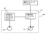
図2Aにおいて、作業機械1の各駆動アクチュエータ7,11,13,15はメインポンプ101から供給される圧油によって駆動される。駆動油圧回路100Aは、各駆動アクチュエータ7,11,13,15に圧油を供給するための回路であり、主に、エンジン5によって駆動されるメインポンプ101およびパイロットポンプ102と、メインポンプ101と接続され、駆動アクチュエータへの供給流量を制御するパイロット式流量制御弁群110と、パイロットポンプ102と接続され、操作レバー50の操作に応じて流量制御弁群110に供給するパイロット圧油を生成する比例減圧弁群120とから構成される。   In FIG. 2A, the drive actuators 7, 11, 13, and 15 of the work machine 1 are driven by pressure oil supplied from the main pump 101. The drive hydraulic circuit 100A is a circuit for supplying pressure oil to each of the drive actuators 7, 11, 13, 15 and mainly includes a main pump 101 and a pilot pump 102 driven by the engine 5, a main pump 101, A pilot-type flow control valve group 110 connected to control the flow rate supplied to the drive actuator and a pilot pump 102 are connected to generate pilot pressure oil to be supplied to the flow control valve group 110 according to the operation of the operation lever 50. And a proportional pressure reducing valve group 120.

流量制御弁群110は、ブーム流量制御弁111、アーム流量制御弁113、アタッチメント流量制御弁115、旋回流量制御弁117から構成される。比例減圧弁群120は、ブーム伸長比例減圧弁121、ブーム縮小比例減圧弁122、アーム伸長比例減圧弁123、アーム縮小比例減圧弁124、アタッチメント伸長比例減圧弁125、アタッチメント縮小比例減圧弁126、右旋回比例減圧弁127、左旋回比例減圧弁128から構成される。   The flow control valve group 110 includes a boom flow control valve 111, an arm flow control valve 113, an attachment flow control valve 115, and a turning flow control valve 117. The proportional pressure reducing valve group 120 includes a boom extension proportional pressure reducing valve 121, a boom reduction proportional pressure reducing valve 122, an arm extension proportional pressure reducing valve 123, an arm reduction proportional pressure reducing valve 124, an attachment extension proportional pressure reducing valve 125, an attachment reduction proportional pressure reducing valve 126, a right side. The turning proportional pressure reducing valve 127 and the left turning proportional pressure reducing valve 128 are configured.

なお、駆動アクチュエータの駆動方法はいずれの駆動アクチュエータでも同様であるため、以下では、ブームシリンダ11を例にとって説明する。   In addition, since the drive method of a drive actuator is the same also in any drive actuator, below, it demonstrates taking the boom cylinder 11 as an example.

図2Bに油圧パイロット式操作装置を有する一般的な作業機械におけるブームシリンダ11の駆動油圧回路100Aの概略構成図を示す。   FIG. 2B shows a schematic configuration diagram of a drive hydraulic circuit 100A of the boom cylinder 11 in a general work machine having a hydraulic pilot type operating device.

図2Bにおいて、ブーム比例減圧弁は、ブーム伸長比例減圧弁121と、ブーム縮小比例減圧弁122とから構成される。これらの比例減圧弁121,122は、ブーム操作レバー50bを伸長側あるいは縮小側に操作することにより駆動され、パイロットポンプ102の吐出する圧油からブーム操作レバー50bの操作量に対応する圧力のパイロット圧油を生成する。   In FIG. 2B, the boom proportional pressure reducing valve includes a boom extension proportional pressure reducing valve 121 and a boom reduction proportional pressure reducing valve 122. These proportional pressure reducing valves 121 and 122 are driven by operating the boom operation lever 50b to the expansion side or the contraction side, and pilots having a pressure corresponding to the operation amount of the boom operation lever 50b from the pressure oil discharged from the pilot pump 102. Generate pressure oil.

ブーム伸長比例減圧弁121は、第一ポート121a、第二ポート121b、および第三ポート121cを備えており、第一ポート121aは作動油タンク103と、第二ポート121bはパイロットポンプ102と、第三ポート121cは後述するブーム流量制御弁111のブーム伸長側パイロットポート111eと接続される。ブーム操作レバー50bを伸長側に操作していない場合には、第一ポート121aと第三ポート121cとを連通する弁路が全開、第二ポート121bが全閉となり、パイロットポンプ102からの圧油は第三ポート121cへ供給されない。ブーム操作レバー50bが伸長側に操作されると、その操作によって、第二ポート121bと第三ポート121cとを連通する弁路が開くように駆動され、パイロットポンプ102から第三ポート121cへパイロット圧油が供給され、レバー操作量に応じた圧力の圧油が第三ポート121cから出力される。ブーム操作レバー50bを操作状態から非操作状態に戻す方向に操作すると、ブーム伸長比例減圧弁121は、第二ポート121bと第三ポート121cとを連通する弁路を閉じ、第一ポート121aと第三ポート121cとを連通する弁路を開く方向に駆動され、非操作状態まで戻されると、第一ポート121aと第三ポート121cとを連通する弁路が全開となる。この時、第三ポート121cに接続されるパイロット油路の圧油は、第一ポート121aと第三ポート121cとを連通する弁路を流通して作動油タンク103に排出される。   The boom extension proportional pressure reducing valve 121 includes a first port 121a, a second port 121b, and a third port 121c. The first port 121a is a hydraulic oil tank 103, the second port 121b is a pilot pump 102, The three port 121c is connected to a boom extension side pilot port 111e of a boom flow rate control valve 111 described later. When the boom operation lever 50b is not operated to the extended side, the valve path communicating the first port 121a and the third port 121c is fully opened, the second port 121b is fully closed, and the pressure oil from the pilot pump 102 is Is not supplied to the third port 121c. When the boom operation lever 50b is operated to the extension side, the operation is driven so that the valve path communicating the second port 121b and the third port 121c is opened, and the pilot pressure is supplied from the pilot pump 102 to the third port 121c. Oil is supplied and pressure oil having a pressure corresponding to the lever operation amount is output from the third port 121c. When the boom operating lever 50b is operated in a direction to return from the operating state to the non-operating state, the boom extension proportional pressure reducing valve 121 closes the valve path that connects the second port 121b and the third port 121c, and the first port 121a and the first port When it is driven in the direction to open the valve path communicating with the three ports 121c and returned to the non-operating state, the valve path communicating with the first port 121a and the third port 121c is fully opened. At this time, the pressure oil in the pilot oil passage connected to the third port 121c flows through the valve passage communicating the first port 121a and the third port 121c, and is discharged to the hydraulic oil tank 103.

ブーム縮小比例減圧弁122はブーム伸長比例減圧弁121と同様の構成を有している。ブーム操作レバー50bが縮小側に操作された場合には、ブーム伸長比例減圧弁121の代わりにブーム縮小比例減圧弁122が駆動され、レバー操作量に応じた圧力の圧油がブーム縮小比例減圧弁122の第三ポート122cから出力される。また、ブーム操作レバー50bを縮小側に操作した状態から非操作状態に戻す方向に操作すると、ブーム縮小比例減圧弁122の第三ポート122cに接続されるパイロット油路の圧油は、第一ポート122aと第三ポート122cとを連通する弁路を流通して作動油タンク103に排出される。   The boom reduction proportional pressure reducing valve 122 has the same configuration as the boom extension proportional pressure reducing valve 121. When the boom operation lever 50b is operated to the reduction side, the boom reduction proportional pressure reducing valve 122 is driven instead of the boom extension proportional pressure reducing valve 121, and the pressure oil corresponding to the lever operation amount is supplied to the boom reduction proportional pressure reducing valve. 122 from the third port 122c. Further, when the boom operation lever 50b is operated in a direction to return from the state where the boom operation lever 50b is operated to the reduction side to the non-operation state, the pressure oil in the pilot oil passage connected to the third port 122c of the boom reduction proportional pressure reducing valve 122 is The fluid flows through a valve path that connects 122 a and the third port 122 c and is discharged to the hydraulic oil tank 103.

ブーム流量制御弁111は、ブーム伸長側パイロットポート111eとブーム縮小側パイロットポート111sを有するパイロット式の3位置切換弁である。ブーム伸長側パイロットポート111eには、ブーム伸長比例減圧弁121がブーム伸長側パイロット油路を介して接続され、ブーム縮小側パイロットポート111sには、ブーム縮小比例減圧弁122がブーム縮小側パイロット油路を介して接続される。また、ブーム流量制御弁111のアクチュエータ側ポート111a,111bは、それぞれブーム伸長側メイン油路およびブーム縮小側メイン油路を介してブームシリンダ11のボトム側油室11bおよびロッド側油室11rに接続される。ブーム流量制御弁111のポンプポート111pはメインポンプ101と、タンクポート111tは作動油タンク103とそれぞれ接続されている。   The boom flow rate control valve 111 is a pilot-type three-position switching valve having a boom extension side pilot port 111e and a boom reduction side pilot port 111s. A boom extension proportional pressure reducing valve 121 is connected to the boom extension side pilot port 111e via a boom extension side pilot oil passage, and a boom reduction proportional pressure reducing valve 122 is connected to the boom reduction side pilot port 111s. Connected through. The actuator side ports 111a and 111b of the boom flow control valve 111 are connected to the bottom side oil chamber 11b and the rod side oil chamber 11r of the boom cylinder 11 via the boom extension side main oil passage and the boom reduction side main oil passage, respectively. Is done. The pump port 111p of the boom flow control valve 111 is connected to the main pump 101, and the tank port 111t is connected to the hydraulic oil tank 103, respectively.

ブーム流量制御弁111のブーム伸長側パイロットポート111eとブーム縮小側パイロットポート111sとのいずれにもパイロット圧油が供給されていない場合には、ブーム流量制御弁111は中立位置となり、ブームシリンダ11への圧油の供給およびブームシリンダ11からの圧油の排出は行われない。ブーム操作レバー50bが伸長側に操作され、ブーム伸長側パイロットポート111eにパイロット圧油が供給されると、ブーム流量制御弁111は伸長駆動位置に切り換わり、メインポンプ101からの圧油がブームシリンダ11のボトム側油室11bに供給される。これにより、ブームシリンダ11は伸長駆動される。一方、ブーム操作レバー50bが縮小側に操作された場合には、ブーム縮小側パイロットポート111sにパイロット圧油が供給され、ブーム流量制御弁111が縮小駆動位置に切り換わり、メインポンプ101からの圧油がブームシリンダ11のロッド側油室11rに供給される。これにより、ブームシリンダ11は縮小駆動される。この時、ブーム流量制御弁111の開口面積は、各パイロットポート111e,111sに供給されるパイロット圧油の圧力によって決定され、ブームシリンダ11はパイロット圧油の圧力に応じた速度で伸縮駆動される。   When pilot pressure oil is not supplied to either the boom extension side pilot port 111 e or the boom reduction side pilot port 111 s of the boom flow rate control valve 111, the boom flow rate control valve 111 is in the neutral position, and to the boom cylinder 11. No pressure oil is supplied and no pressure oil is discharged from the boom cylinder 11. When the boom operation lever 50b is operated to the extension side and the pilot pressure oil is supplied to the boom extension side pilot port 111e, the boom flow control valve 111 is switched to the extension drive position, and the pressure oil from the main pump 101 is supplied to the boom cylinder. 11 is supplied to the bottom oil chamber 11b. Thereby, the boom cylinder 11 is driven to extend. On the other hand, when the boom operation lever 50b is operated to the reduction side, the pilot pressure oil is supplied to the boom reduction side pilot port 111s, the boom flow control valve 111 is switched to the reduction drive position, and the pressure from the main pump 101 is changed. Oil is supplied to the rod side oil chamber 11 r of the boom cylinder 11. Thereby, the boom cylinder 11 is driven to reduce. At this time, the opening area of the boom flow control valve 111 is determined by the pressure of the pilot pressure oil supplied to the pilot ports 111e and 111s, and the boom cylinder 11 is driven to extend and contract at a speed corresponding to the pressure of the pilot pressure oil. .

≪安定化制御≫
本実施形態に係る作業機械1には、作業中の不安定化を防ぐ安定化制御装置190が搭載されている。作業機械1では、オペレータが操作レバー50を操作することにより、種々の作業が行われるが、作業フロント6を伸ばした姿勢で作業を行う場合やアタッチメント23に加わる負荷が大きい場合には安定性が低下する。また、急操作を行った場合には、急激な速度変化に伴って大きな慣性力が作用し、その影響により、作業機械1の安定性が大きく変化する。特に、操作レバー50を操作状態から瞬時に停止指令状態に戻すような急停止操作時には、転倒方向に大きな慣性力が働き、作業機械1が不安定になりやすい。
≪Stabilization control≫
The work machine 1 according to the present embodiment is equipped with a stabilization control device 190 that prevents instability during work. In the work machine 1, various operations are performed by the operator operating the operation lever 50. However, when the work is performed with the work front 6 extended, or when the load applied to the attachment 23 is large, the stability is improved. descend. In addition, when an abrupt operation is performed, a large inertial force acts with a rapid speed change, and the stability of the work machine 1 greatly changes due to the influence. In particular, during a sudden stop operation in which the operation lever 50 is instantaneously returned from the operation state to the stop command state, a large inertia force acts in the direction of overturning, and the work machine 1 tends to become unstable.

本実施形態の安定化制御装置190は、無理な操作や誤った操作を行った場合であっても作業機械1が不安定にならないよう、安定性評価に基づいて駆動アクチュエータの動作を制限する装置である。また、本実施形態の安定化制御装置190は、急停止操作により安定性が大幅に低下することを考慮し、作業機械1を安定に保つための動作制限として、緩停止と動作速度制限を行う。   The stabilization control device 190 of the present embodiment is a device that restricts the operation of the drive actuator based on the stability evaluation so that the work machine 1 does not become unstable even when an unreasonable operation or an erroneous operation is performed. It is. In addition, the stabilization control device 190 according to the present embodiment performs a slow stop and a speed limit as an operation limit for keeping the work machine 1 stable in consideration of the fact that the stability is greatly reduced by the sudden stop operation. .

ここで、緩停止とは停止操作時の可動部の減速加速度を制限し、可動部を緩やかに停止させる作用であり、動作速度制限とは駆動アクチュエータの最大速度を制限する作用である。緩停止を導入することにより、急停止操作時に発生する慣性力を抑制することができ、急停止に伴って発生する大きな慣性力によって作業機械1が不安定になることを防ぐことができる。一方、緩停止を行うと、制動距離が増大するため、あらかじめ許容制動距離を定め、許容制動距離内で停止できるように停止特性を設定する必要がある。そこで、本実施形態の安定化制御装置190は、あらかじめ定められた許容制動距離の範囲内で必要に応じて緩停止を行い、また、いかなる動作状態においても許容制動距離内で安定に作業できるように動作速度を制限する。   Here, the slow stop is an action of limiting the deceleration acceleration of the movable part at the time of the stop operation and gently stopping the movable part, and the operation speed limit is an action of limiting the maximum speed of the drive actuator. By introducing the slow stop, the inertia force generated during the sudden stop operation can be suppressed, and the work machine 1 can be prevented from becoming unstable due to the large inertia force generated by the sudden stop. On the other hand, if a gentle stop is performed, the braking distance increases. Therefore, it is necessary to set an allowable braking distance in advance and set a stop characteristic so that the vehicle can stop within the allowable braking distance. Therefore, the stabilization control device 190 according to the present embodiment performs a gentle stop as necessary within a predetermined allowable braking distance, and can stably work within the allowable braking distance in any operating state. Limit the operating speed.

安定化制御装置190は、作業機械1に備えられた全ての駆動アクチュエータに対して動作制限を行うように構成されている。しかし、以下では、作業機械1の安定性に特に大きな影響を与えるブームシリンダ11とアームシリンダ13に対してのみ、動作制限を適用するように構成した場合を例にとって説明する。   The stabilization control device 190 is configured to limit the operation of all the drive actuators provided in the work machine 1. However, in the following, a case will be described as an example in which the operation restriction is applied only to the boom cylinder 11 and the arm cylinder 13 that have a particularly great influence on the stability of the work machine 1.

図3に本実施形態の安定化制御装置190の概略構成図を示す。   FIG. 3 shows a schematic configuration diagram of the stabilization control device 190 of the present embodiment.

図3において、安定化制御装置190は、主に、状態量検出部30と、演算装置60と、パイロット圧補正部200とから構成される。   In FIG. 3, the stabilization control device 190 mainly includes a state quantity detection unit 30, a calculation device 60, and a pilot pressure correction unit 200.

状態量検出部30は、作業機械1の状態量を検出するために作業機械1の各所に取り付けられたセンサである。   The state quantity detection unit 30 is a sensor attached to each part of the work machine 1 in order to detect the state quantity of the work machine 1.

演算装置60は、図示しないCPU(Central Processng Unt)、記憶装置等から構成され、状態量検出部30の検出信号に基づいて、安定化制御演算を行い、作業機械1を安定に保つために必要なブームシリンダ11およびアームシリンダ13の動作制限を算出し、パイロット圧補正部200への駆動指令を出力する。   The arithmetic device 60 is composed of a CPU (Central Process Unt), a storage device, etc. (not shown), and is necessary for performing a stabilization control calculation based on the detection signal of the state quantity detection unit 30 and keeping the work machine 1 stable. The operation limits of the boom cylinder 11 and the arm cylinder 13 are calculated, and a drive command to the pilot pressure correction unit 200 is output.

パイロット圧補正部200は、オペレータからのレバー操作によって生成されるパイロット圧油の圧力を、演算装置60において算出された動作制限を満たすように補正する油圧装置であり、流量制御弁群110と比例減圧弁群120とを接続するパイロット油路に設けられている。   The pilot pressure correction unit 200 is a hydraulic device that corrects the pressure of the pilot pressure oil generated by the lever operation from the operator so as to satisfy the operation restriction calculated by the calculation device 60, and is proportional to the flow control valve group 110. A pilot oil passage that connects the pressure reducing valve group 120 is provided.

以下、各部の詳細を説明する。   Details of each part will be described below.

<状態量検出部>
作業機械1の主要部分には、状態量検出部30として、機械の状態量を検出するセンサが備えられる。以下、本実施形態に係る作業機械1に備えられる状態量検出部30の詳細について、図1および図3を参照して説明する。
<State quantity detection unit>
A main part of the work machine 1 is provided with a sensor that detects a state quantity of the machine as the state quantity detection unit 30. Hereinafter, the details of the state quantity detection unit 30 provided in the work machine 1 according to the present embodiment will be described with reference to FIGS. 1 and 3.

本実施形態の状態量検出部30は、作業機械1の姿勢を検出する姿勢検出部49と、各駆動アクチュエータに対するオペレータからの動作指令量を検出するレバー操作量検出部50aとから構成される。   The state quantity detection unit 30 of the present embodiment includes an attitude detection unit 49 that detects the attitude of the work machine 1 and a lever operation amount detection unit 50a that detects an operation command amount from an operator for each drive actuator.

姿勢検出部49は、作業機械1の姿勢を検出する機能ブロックであり、姿勢センサ3b、各角度センサ3s,40a,41a,42aから構成される。旋回体3には、作業機械1の傾きを検出するための姿勢センサ3bが設けられる。また、旋回体3の中心軸3c上には、走行体2と旋回体3の旋回角度を検出するための旋回角度センサ3sが設けられる。旋回体3とブーム10の支点40には、ブーム10の回動角度を計測するためのブーム角度センサ40aが設けられる。ブーム10とアーム12の支点41には、アーム12の回動角度を計測するためのアーム角度センサ41aが設けられる。アーム12とアタッチメント23の支点42には、アタッチメント角度センサ42aが設けられる。   The posture detection unit 49 is a functional block that detects the posture of the work machine 1 and includes a posture sensor 3b and angle sensors 3s, 40a, 41a, and 42a. The swing body 3 is provided with a posture sensor 3b for detecting the tilt of the work machine 1. A turning angle sensor 3 s for detecting the turning angle between the traveling body 2 and the turning body 3 is provided on the central axis 3 c of the turning body 3. A boom angle sensor 40 a for measuring the rotation angle of the boom 10 is provided at the fulcrum 40 of the revolving structure 3 and the boom 10. An arm angle sensor 41 a for measuring the rotation angle of the arm 12 is provided at the fulcrum 41 of the boom 10 and the arm 12. An attachment angle sensor 42 a is provided at the fulcrum 42 of the arm 12 and the attachment 23.

レバー操作量検出部50aは、作業機械1の各駆動アクチュエータに対するオペレータからの動作指令量を検出する機能ブロックであり、操作レバー50の操作量を検出するレバー操作量センサが設けられる。前述の油圧パイロット式操作装置では、操作レバー50を操作すると比例減圧弁群120のうちの対応する比例減圧弁が駆動され、レバー操作量に応じた圧力のパイロット圧油が出力される。したがって、各比例減圧弁の出力する圧油の圧力を検出する圧力センサを設けることにより、オペレータからの動作指令量を検出することができる。   The lever operation amount detection unit 50 a is a functional block that detects an operation command amount from an operator for each drive actuator of the work machine 1, and is provided with a lever operation amount sensor that detects an operation amount of the operation lever 50. In the hydraulic pilot type operating device described above, when the operation lever 50 is operated, the corresponding proportional pressure reducing valve in the proportional pressure reducing valve group 120 is driven, and pilot pressure oil having a pressure corresponding to the lever operation amount is output. Therefore, by providing a pressure sensor that detects the pressure of the pressure oil output from each proportional pressure reducing valve, the operation command amount from the operator can be detected.

より具体的には、ブーム伸長比例減圧弁121の出力する圧油の圧力を検出するブーム伸長操作量センサ51と、ブーム縮小比例減圧弁122の出力する圧油の圧力を検出するブーム縮小操作量センサ52と、アーム伸長比例減圧弁123の出力する圧油の圧力を検出するアーム伸長操作量センサ53と、アーム縮小比例減圧弁の124出力する圧油の圧力を検出するアーム縮小操作量センサ54と、アタッチメント伸長比例減圧弁125の出力する圧油の圧力を検出するアタッチメント伸長操作量センサ55と、アタッチメント縮小比例減圧弁126の出力する圧油の圧力を検出するアタッチメント縮小操作量センサ56と、右旋回比例減圧弁127の出力する圧油の圧力を検出する右旋回操作量センサ57と、左旋回比例減圧弁128の出力する圧油の圧力を検出する左旋回操作量センサ58とが設けられる。   More specifically, a boom extension operation amount sensor 51 that detects the pressure oil pressure output from the boom extension proportional pressure reducing valve 121 and a boom reduction operation amount that detects the pressure oil pressure output from the boom reduction proportional pressure reducing valve 122. The sensor 52, the arm extension operation amount sensor 53 that detects the pressure oil pressure output from the arm extension proportional pressure reducing valve 123, and the arm reduction operation amount sensor 54 that detects the pressure oil pressure output from the arm reduction proportional pressure reducing valve 124. An attachment extension operation amount sensor 55 for detecting the pressure oil pressure output from the attachment extension proportional pressure reducing valve 125; an attachment reduction operation amount sensor 56 for detecting the pressure oil pressure output from the attachment reduction proportional pressure reducing valve 126; A right turn operation amount sensor 57 for detecting the pressure of the pressure oil output from the right turn proportional pressure reducing valve 127, and a left turn proportional pressure reducing valve 128. A left rotation operation amount sensor 58 for detecting a pressure force to the pressure oil is provided.

<パイロット圧補正部>
パイロット圧補正部200は、オペレータのレバー操作に応じて比例減圧弁群から出力されるパイロット圧油の圧力を、後述する演算装置60内の安定化制御演算部60aから指令される動作制限を満たす圧力に補正する機能ブロックである。本実施形態の安定化制御装置190では、安定化のための動作制限として、停止特性を変更して緩やかに停止させる緩停止と、動作速度に上限を設ける動作速度制限を行う。パイロット圧補正部200は、この2種類の動作制限を行うために、停止特性変更部210と動作速度制限部240とを備えている。
<Pilot pressure correction unit>
The pilot pressure correction unit 200 satisfies the operation restriction instructed by the stabilization control calculation unit 60a in the calculation device 60 described later, with respect to the pressure of the pilot pressure oil output from the proportional pressure reducing valve group in accordance with the lever operation of the operator. This is a functional block for correcting pressure. In the stabilization control device 190 of the present embodiment, as an operation restriction for stabilization, a slow stop that changes a stop characteristic and stops gently, and an operation speed restriction that sets an upper limit on the operation speed are performed. The pilot pressure correction unit 200 includes a stop characteristic changing unit 210 and an operation speed limiting unit 240 in order to perform these two types of operation limitation.

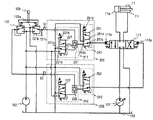
図5Aに、本実施形態の安定化制御装置190におけるパイロット圧補正部200を備えた駆動アクチュエータの駆動油圧回路の概念図を示す。   FIG. 5A is a conceptual diagram of a drive hydraulic circuit of a drive actuator provided with a pilot pressure correction unit 200 in the stabilization control device 190 of the present embodiment.

安定化制御演算に基づく動作制限をブームシリンダ11およびアームシリンダ13に対して適用する場合、作業機械1はパイロット圧補正部200として、図5Aに示すようにブーム伸長パイロット圧補正部201、ブーム縮小パイロット圧補正部202、アーム伸長パイロット圧補正部203、アーム縮小パイロット圧補正部204が設けられる。   When the operation restriction based on the stabilization control calculation is applied to the boom cylinder 11 and the arm cylinder 13, the work machine 1 serves as a pilot pressure correction unit 200, as shown in FIG. 5A, a boom extension pilot pressure correction unit 201, a boom reduction A pilot pressure correction unit 202, an arm extension pilot pressure correction unit 203, and an arm reduction pilot pressure correction unit 204 are provided.

ブーム伸長パイロット圧補正部201はブーム伸長停止特性変更部211とブーム伸長動作速度制限部241を、ブーム縮小パイロット圧補正部202はブーム縮小停止特性変更部212とブーム縮小動作速度制限部242を、アーム伸長パイロット圧補正部203はアーム伸長停止特性変更部213とアーム伸長動作速度制限部243を、アーム縮小パイロット圧補正部204はアーム縮小停止特性変更部214とアーム縮小動作速度制限部244をそれぞれ備えている。各パイロット圧補正部201,202,203,204の構成はいずれについても同様であるため、以下では、ブーム伸長パイロット圧油の補正を例にとり、図5Bを参照してブーム伸長パイロット圧補正部201の詳細を説明する。   The boom extension pilot pressure correction unit 201 includes a boom extension stop characteristic change unit 211 and a boom extension operation speed limit unit 241, and the boom reduction pilot pressure correction unit 202 includes a boom reduction stop characteristic change unit 212 and a boom reduction operation speed limit unit 242. The arm extension pilot pressure correcting unit 203 includes an arm extension / stop characteristic changing unit 213 and an arm extension operation speed limiting unit 243, and the arm reduction pilot pressure correcting unit 204 includes an arm reduction / stop characteristic changing unit 214 and an arm reduction operation speed limiting unit 244, respectively. I have. Since the configurations of the pilot pressure correction units 201, 202, 203, and 204 are the same, hereinafter, the boom extension pilot pressure correction unit 201 will be described with reference to FIG. Details will be described.

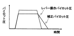
前述のように、ブームシリンダ11の動作は、ブーム流量制御弁111の各パイロットポート111e,111sに供給されるパイロット圧油の圧力によって決定される。したがって、何らかの制御を導入し、制御演算結果に基づいてブームシリンダ11を伸長駆動するためには、ブーム流量制御弁111のブーム伸長側パイロットポート111eにパイロット圧油を供給するパイロット油路に、レバー操作に応じて比例減圧弁121から出力されるパイロット圧油の圧力を補正し、制御演算結果を満たす圧力の圧油を生成するパイロット圧補正部201を設ければ良い。以下では、レバー操作に応じて比例減圧弁121から出力されるパイロット圧油をレバー操作パイロット圧油、レバー操作パイロット圧油の圧力をレバー操作パイロット圧と呼び、パイロット圧補正部201によって補正されたパイロット圧油を補正パイロット圧油、補正パイロット圧油の圧力を補正パイロット圧と呼ぶ。   As described above, the operation of the boom cylinder 11 is determined by the pressure of the pilot pressure oil supplied to the pilot ports 111e and 111s of the boom flow control valve 111. Therefore, in order to introduce some control and drive the boom cylinder 11 to extend based on the control calculation result, a lever is provided in the pilot oil passage that supplies the pilot pressure oil to the boom extension side pilot port 111e of the boom flow control valve 111. A pilot pressure correction unit 201 that corrects the pressure of the pilot pressure oil output from the proportional pressure reducing valve 121 according to the operation and generates pressure oil having a pressure that satisfies the control calculation result may be provided. Hereinafter, the pilot pressure oil output from the proportional pressure reducing valve 121 in response to the lever operation is referred to as a lever operation pilot pressure oil, and the pressure of the lever operation pilot pressure oil is referred to as a lever operation pilot pressure, and is corrected by the pilot pressure correction unit 201. The pilot pressure oil is called a corrected pilot pressure oil, and the pressure of the corrected pilot pressure oil is called a corrected pilot pressure.

制御演算結果に基づく所望のパイロット圧を生成する方法としては、パイロットポンプ102とブーム流量制御弁111とを接続するパイロット油路に電気指令に基づいてパイロットポンプ102が吐出する圧油を減圧して出力する電磁比例弁を設ける構成が考えられる。電磁比例弁を制御演算結果に基づいて駆動し、電磁比例弁から出力されるパイロット圧油を例えば比例減圧弁121から出力されるパイロット圧油の代わりにブーム流量制御弁111に供給する構成とすることによって、所望の圧力のパイロット圧油をブーム流量制御弁111に供給できる。このような構成とした場合には、レバー操作パイロット圧油に対する補正の要否にかかわらず、追加した電磁比例弁からの圧油がブーム流量制御弁111へ供給される。   As a method of generating a desired pilot pressure based on the control calculation result, the pressure oil discharged from the pilot pump 102 is reduced in the pilot oil passage connecting the pilot pump 102 and the boom flow rate control valve 111 based on the electrical command. A configuration in which an electromagnetic proportional valve for output is provided is conceivable. The electromagnetic proportional valve is driven based on the control calculation result, and the pilot pressure oil output from the electromagnetic proportional valve is supplied to the boom flow control valve 111 instead of the pilot pressure oil output from the proportional pressure reducing valve 121, for example. Thus, pilot pressure oil having a desired pressure can be supplied to the boom flow rate control valve 111. In such a configuration, the pressure oil from the added electromagnetic proportional valve is supplied to the boom flow rate control valve 111 regardless of the necessity of correction for the lever operation pilot pressure oil.

一方、パイロット圧補正部201を設けるにあたっては、従来の操作性を損なわないように構成する必要がある。前述のように電磁比例弁を設ける構成では、常に従来とは異なる構成でブーム流量制御弁111へパイロット圧油を供給するため、応答性等が変化し、操作の違和感を生む恐れがある。従来の操作性を維持するためには、補正の必要のない場合には、パイロット圧補正部201を設けない場合と同様に、例えば比例減圧弁121から出力されるレバー操作パイロット圧油をブーム流量制御弁111のパイロットポート111eに供給し、補正が必要な場合のみ、レバー操作パイロット圧を補正する構成とすることが望ましい。そこで、本実施形態では、比例減圧弁121を用いた従来のパイロット圧油供給回路を生かしつつ、安定化制御演算によって動作制限が必要と判断された場合のみ、レバー操作パイロット圧に対して補正を行うようにパイロット圧補正部201を構成する。   On the other hand, in providing the pilot pressure correction unit 201, it is necessary to configure so as not to impair the conventional operability. In the configuration in which the electromagnetic proportional valve is provided as described above, the pilot pressure oil is always supplied to the boom flow rate control valve 111 with a configuration different from the conventional one. In order to maintain the conventional operability, when no correction is required, the lever operation pilot pressure oil output from, for example, the proportional pressure reducing valve 121 is used as the boom flow rate as in the case where the pilot pressure correction unit 201 is not provided. It is desirable that the lever operation pilot pressure is corrected only when it is supplied to the pilot port 111e of the control valve 111 and correction is necessary. Therefore, in the present embodiment, the lever operation pilot pressure is corrected only when it is determined that the operation restriction is necessary by the stabilization control calculation while utilizing the conventional pilot pressure oil supply circuit using the proportional pressure reducing valve 121. The pilot pressure correction unit 201 is configured to perform this.

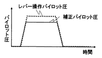
本実施形態の安定化制御装置190において行われる動作制限は、停止特性を変更して緩やかに停止させる緩停止と、動作速度に上限を設ける動作速度制限である。緩停止を行うためには、レバー操作パイロット圧が急激に低下する場合に、圧力の低下が緩やかになるように補正する必要がある。一方、動作速度制限を行うためには、レバー操作パイロット圧に対して上限圧を設定する必要がある。緩停止を行うための補正例を図4Aに、動作速度制限を行うための補正例を図4Bに示した。   The operation restriction performed in the stabilization control device 190 of the present embodiment is a slow stop in which the stop characteristic is changed to stop gently, and an operation speed restriction in which an upper limit is set for the operation speed. In order to perform the slow stop, it is necessary to correct so that the pressure drop becomes gentle when the lever operation pilot pressure suddenly drops. On the other hand, in order to limit the operation speed, it is necessary to set an upper limit pressure for the lever operation pilot pressure. A correction example for performing a slow stop is shown in FIG. 4A, and a correction example for limiting the operation speed is shown in FIG. 4B.

本実施形態のパイロット圧補正部201は、前述の2種類の動作制限(緩停止と動作速度制限)を行うために、停止特性変更部211と動作速度制限部241とを備えている。比例減圧弁121から出力されたレバー操作パイロット圧油は、まず、停止特性変更部211に入力され、演算装置60内で行われる安定化制御演算により指令された緩停止の停止特性を満たすように補正される。この停止特性変更部211によって補正されたパイロット圧油は動作速度制限部241に入力され、演算装置60内で行われる安定化制御演算により指令された動作速度制限を満たすように補正される。この動作速度制限部241によって補正されたパイロット圧油は、対応するブーム流量制御弁111のブーム伸長側パイロットポート111eに入力される。   The pilot pressure correction unit 201 of the present embodiment includes a stop characteristic changing unit 211 and an operation speed limiting unit 241 in order to perform the above-described two types of operation limitation (slow stop and operation speed limitation). The lever operation pilot pressure oil output from the proportional pressure reducing valve 121 is first input to the stop characteristic changing unit 211 so as to satisfy the stop characteristic of slow stop commanded by the stabilization control calculation performed in the arithmetic unit 60. It is corrected. The pilot pressure oil corrected by the stop characteristic changing unit 211 is input to the operating speed limiting unit 241 and corrected so as to satisfy the operating speed limit commanded by the stabilization control calculation performed in the calculation device 60. The pilot pressure oil corrected by the operation speed limiter 241 is input to the boom extension side pilot port 111e of the corresponding boom flow rate control valve 111.

本実施形態のパイロット圧補正部201において、停止特性変更部211は、緩停止用電磁比例弁221と緩停止用高圧選択部231とから構成され、動作速度制限部241は速度制限用電磁比例弁251から構成される。緩停止用電磁比例弁221および速度制限用電磁比例弁251は後述する演算装置60から出力される指令信号により駆動される。   In the pilot pressure correcting unit 201 of the present embodiment, the stop characteristic changing unit 211 includes a slow stop electromagnetic proportional valve 221 and a slow stop high pressure selecting unit 231, and the operating speed limiting unit 241 is a speed limiting electromagnetic proportional valve. 251. The slow stop electromagnetic proportional valve 221 and the speed limiting electromagnetic proportional valve 251 are driven by a command signal output from the arithmetic unit 60 described later.

・停止特性変更部
本実施形態のブーム伸長停止特性変更部211は、上述したように緩停止用電磁比例弁221と緩停止用高圧選択部231とから構成される。
-Stop characteristic change part The boom extension stop characteristic change part 211 of this embodiment is comprised from the electromagnetic proportional valve 221 for slow stops, and the high pressure selection part 231 for slow stops as mentioned above.

緩停止用電磁比例弁221は、演算装置60からの指令により駆動され、パイロットポンプ102から吐出される圧油から演算装置60内の安定化制御演算部60aにより指令された緩停止を行うためのパイロット圧油(緩停止パイロット圧油)を生成する弁である。また、緩停止用高圧選択部231は、レバー操作パイロット圧油と、緩停止パイロット圧油とのうち高圧側の圧油を選択して出力するブロックである。   The slow stop electromagnetic proportional valve 221 is driven by a command from the calculation device 60, and performs a slow stop commanded by the stabilization control calculation unit 60a in the calculation device 60 from the pressure oil discharged from the pilot pump 102. A valve that generates pilot pressure oil (slow stop pilot pressure oil). The slow stop high pressure selector 231 is a block that selects and outputs the pressure oil on the high pressure side of the lever operation pilot pressure oil and the slow stop pilot pressure oil.

緩停止用電磁比例弁221は、第一ポート221a、第二ポート221b、第三ポート221c、およびソレノイド221dを備えている。第一ポート221aには作動油タンク103が、第二ポート221bにはパイロットポンプ102がそれぞれ接続される。演算装置60からの指令信号によってソレノイド221dが励磁されると、指令信号に応じた圧力の緩停止パイロット圧油が第三ポート221cに出力される。緩停止用電磁比例弁221はソレノイド221dが励磁されていない時に、第一ポート221aと第三ポート221cとを連通する弁路が全開、第二ポート221bが全閉となり、パイロットポンプ102からの圧油の供給が遮断される常時閉式の特性を持つ。したがって、ソレノイド221dが非励磁状態の場合には、第三ポート221c側の圧力はタンク圧となる。演算装置60からの指令信号によってソレノイド221dが励磁されると、第二ポート221bと第三ポート221cが連通する弁路が開く方向に駆動され、パイロットポンプ102からの圧油が第三ポート221cに出力される。緩停止用電磁比例弁221は、ソレノイド221dに与えられる指令信号が大きくなるにつれて、第三ポート221cから出力される圧油の圧力が高くなるような特性を持つ。したがって、第三ポート221cから出力される圧油の圧力を安定化制御演算部60aによって指令された緩停止の停止特性を満たす圧力とするように、演算装置60からソレノイド221dに対して駆動指令を行えば良い。   The slow stop electromagnetic proportional valve 221 includes a first port 221a, a second port 221b, a third port 221c, and a solenoid 221d. The hydraulic oil tank 103 is connected to the first port 221a, and the pilot pump 102 is connected to the second port 221b. When the solenoid 221d is excited by a command signal from the arithmetic device 60, a slowly stopped pilot pressure oil having a pressure corresponding to the command signal is output to the third port 221c. When the solenoid 221d is not energized, the slow stop electromagnetic proportional valve 221 is fully opened, the second port 221b is fully closed, and the pressure from the pilot pump 102 is fully closed. It has a normally closed type that shuts off the oil supply. Therefore, when the solenoid 221d is in a non-excited state, the pressure on the third port 221c side is the tank pressure. When the solenoid 221d is excited by a command signal from the arithmetic unit 60, it is driven in a direction to open the valve path connecting the second port 221b and the third port 221c, and the pressure oil from the pilot pump 102 enters the third port 221c. Is output. The slow stop electromagnetic proportional valve 221 has a characteristic that the pressure of the pressure oil output from the third port 221c increases as the command signal applied to the solenoid 221d increases. Accordingly, a drive command is issued from the computing device 60 to the solenoid 221d so that the pressure of the pressure oil output from the third port 221c is a pressure that satisfies the stop characteristics of the slow stop commanded by the stabilization control computing unit 60a. Just do it.

緩停止用高圧選択部231は、例えばシャトル弁であって、比例減圧弁121から出力されるレバー操作パイロット圧油と緩停止用電磁比例弁から出力される緩停止パイロット圧油とが入力される。緩停止用高圧選択部231は、入力されたレバー操作パイロット圧油と緩停止パイロット圧油とのうち高圧側の圧油を選択して、停止特性変更部211の出力とする。   The slow stop high pressure selector 231 is, for example, a shuttle valve, and is input with the lever operation pilot pressure oil output from the proportional pressure reducing valve 121 and the slow stop pilot pressure oil output from the slow stop electromagnetic proportional valve. . The slow stop high pressure selection unit 231 selects the high pressure side pressure oil from the input lever operation pilot pressure oil and slow stop pilot pressure oil, and outputs it as the output of the stop characteristic changing unit 211.

レバー操作パイロット圧が安定化制御演算部60aにより指令された緩停止の停止特性よりも急激に低下する場合には、緩停止パイロット圧がレバー操作パイロット圧よりも高くなり、緩停止用高圧選択部231により緩停止用パイロット圧油が選択され、指令された停止特性の緩停止が実現される。一方、安定化制御演算部60aによって指令された停止特性よりも緩やかに停止するような操作が行われた場合には、レバー操作パイロット圧が緩停止パイロット圧よりも緩やかに低下するため、緩停止パイロット圧に対してレバー操作パイロット圧が高く、緩停止用高圧選択部231においてレバー操作パイロット圧油が選択される。したがって、この場合には、停止特性変更部211においてレバー操作パイロット圧油は補正されることなく出力される。また、停止特性変更部211におけるパイロット圧油の圧力の補正は、急激に動作速度が低下するような操作が行われた場合を対象としており、それ以外の定常的な動作指令操作時や増速操作時等には緩停止用電磁比例弁221は駆動されない。したがって、このような操作時にも、緩停止用高圧選択部231においてレバー操作パイロット圧油が選択され、レバー操作パイロット圧油は補正されることなく出力される。   When the lever operation pilot pressure suddenly drops below the stop characteristic of the slow stop commanded by the stabilization control calculation unit 60a, the slow stop pilot pressure becomes higher than the lever operation pilot pressure, and the slow stop high pressure selection unit The pilot pressure oil for slow stop is selected by H.231, and the slow stop with the commanded stop characteristic is realized. On the other hand, when an operation is performed to stop more slowly than the stop characteristic commanded by the stabilization control calculation unit 60a, the lever operation pilot pressure gradually decreases below the slow stop pilot pressure, so that the slow stop is performed. The lever operation pilot pressure is higher than the pilot pressure, and the lever operation pilot pressure oil is selected in the slow stop high pressure selection unit 231. Therefore, in this case, the lever operation pilot pressure oil is output without being corrected by the stop characteristic changing unit 211. Moreover, the correction of the pressure of the pilot pressure oil in the stop characteristic changing unit 211 is intended for an operation in which the operation speed is suddenly reduced, and during other steady operation command operations or accelerations. During operation or the like, the slow stop electromagnetic proportional valve 221 is not driven. Accordingly, even during such an operation, the lever operation pilot pressure oil is selected by the slow stop high pressure selection unit 231 and the lever operation pilot pressure oil is output without being corrected.

・動作速度制限部
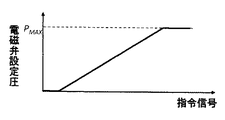
本実施形態では、上述したように、ブーム伸長動作速度制限部241として速度制限用電磁比例弁251を備えている。速度制限用電磁比例弁251は、ブーム流量制御弁111に供給されるパイロット圧油に対し、演算装置60内の安定化制御演算部60aによって指令された動作速度制限を満たすように上限圧を設定する。
Operation Speed Limiting Unit In this embodiment, as described above, the boom extension operation speed limiting unit 241 includes the speed limiting electromagnetic proportional valve 251. The speed limiting electromagnetic proportional valve 251 sets an upper limit pressure so that the pilot pressure oil supplied to the boom flow rate control valve 111 satisfies the operating speed limit commanded by the stabilization control calculation unit 60a in the calculation device 60. To do.

図5Bに示すように、速度制限用電磁比例弁251は、第一ポート251a、第二ポート251b、第三ポート251c、およびソレノイド251dを備えている。第一ポート251aには作動油タンク103が、第二ポート251bには緩停止用高圧選択部231の出力ポートが、第三ポート251cにはブーム流量制御弁111のブーム伸長側パイロットポート111eがそれぞれ接続される。第三ポート251cから出力される圧油が、パイロット圧補正部201による補正パイロット圧油である。   As shown in FIG. 5B, the speed limiting electromagnetic proportional valve 251 includes a first port 251a, a second port 251b, a third port 251c, and a solenoid 251d. The first port 251a has the hydraulic oil tank 103, the second port 251b has the output port of the high pressure selector 231 for slow stop, and the third port 251c has the boom extension side pilot port 111e of the boom flow control valve 111, respectively. Connected. The pressure oil output from the third port 251c is the corrected pilot pressure oil by the pilot pressure correction unit 201.

速度制限用電磁比例弁251は、緩停止用電磁比例弁221と同様、ソレノイド251dが励磁されていない場合には、速度制限用電磁比例弁251の第一ポート251aと第三ポート251cを連通する弁路が全開、第二ポート251bが全閉となる常時閉式の特性を有している。したがって、ソレノイド251dが励磁されていない場合には、ブーム流量制御弁111のブーム伸長側パイロットポート111eは作動油タンク103と連通され、補正パイロット圧はタンク圧となる。一方、演算装置60からの指令信号によってソレノイド251dが励磁されると、第二ポート251bと第三ポート251cとを連通する弁路が開く方向に駆動され、停止特性変更部211から第二ポート251bに供給されるパイロット圧油が、第三ポート251cに出力される。第二ポート251bと第三ポート251cとを連通する弁路を流通する圧油の圧力は、ソレノイド251dに与えられる指令信号の大きさによって決定される。ここで、指令信号によって決定されるのは流通する圧油の上限圧であり、補正パイロット圧は、第二ポート251bに供給される圧油の圧力と、ソレノイド251dに与えられる指令信号によって決定される上限圧との低い方となる。また、ソレノイド251dに対して最大の指令信号を与えた場合には、第二ポート251bに供給される圧油の圧力によらず、第二ポート251bと第三ポート251cとを連通する弁路が全開となり、補正パイロット圧は停止特性変更部211の出力圧と等しくなる。停止特性変更部211の出力圧が安定化制御演算部60aによって指令された動作速度制限を満たす上限圧よりも高い場合には、パイロット圧油は速度制限用電磁比例弁251によって減圧され、指令された動作速度制限が実現される。一方、停止特性変更部211の出力圧が上限圧よりも低い場合には、パイロット圧油は速度制限用電磁比例弁251によって補正されず、停止特性変更部211の出力するパイロット圧油がブーム流量制御弁111のブーム伸長側パイロットポート111eに供給される。また、安定化制御演算部60aにおいて動作速度制限指令が行われない場合も、パイロット圧油は速度制限用電磁比例弁251によって補正されない。   Like the slow stop electromagnetic proportional valve 221, the speed limiting electromagnetic proportional valve 251 communicates the first port 251a and the third port 251c of the speed limiting electromagnetic proportional valve 251 when the solenoid 251d is not excited. It has a normally closed characteristic in which the valve path is fully open and the second port 251b is fully closed. Therefore, when the solenoid 251d is not excited, the boom extension side pilot port 111e of the boom flow control valve 111 is communicated with the hydraulic oil tank 103, and the corrected pilot pressure becomes the tank pressure. On the other hand, when the solenoid 251d is excited by a command signal from the arithmetic device 60, the valve path that connects the second port 251b and the third port 251c is driven to open, and the stop characteristic changing unit 211 supplies the second port 251b. Is supplied to the third port 251c. The pressure of the pressure oil flowing through the valve path communicating with the second port 251b and the third port 251c is determined by the magnitude of the command signal given to the solenoid 251d. Here, what is determined by the command signal is the upper limit pressure of the circulating pressure oil, and the corrected pilot pressure is determined by the pressure oil pressure supplied to the second port 251b and the command signal applied to the solenoid 251d. The lower one with the upper limit pressure. In addition, when the maximum command signal is given to the solenoid 251d, a valve path that communicates the second port 251b and the third port 251c is established regardless of the pressure of the pressure oil supplied to the second port 251b. It becomes fully open, and the corrected pilot pressure becomes equal to the output pressure of the stop characteristic changing unit 211. If the output pressure of the stop characteristic changing unit 211 is higher than the upper limit pressure that satisfies the operating speed limit commanded by the stabilization control calculating unit 60a, the pilot pressure oil is reduced by the speed limiting electromagnetic proportional valve 251 and commanded. Operating speed limitation is realized. On the other hand, when the output pressure of the stop characteristic changing unit 211 is lower than the upper limit pressure, the pilot pressure oil is not corrected by the speed limiting electromagnetic proportional valve 251, and the pilot pressure oil output from the stop characteristic changing unit 211 is the boom flow rate. It is supplied to the boom extension side pilot port 111e of the control valve 111. Even when the operation speed limit command is not issued in the stabilization control calculation unit 60a, the pilot pressure oil is not corrected by the speed limiting electromagnetic proportional valve 251.

以上で説明したように、本実施形態の停止特性変更部211は指令された緩停止を行うために、レバー操作パイロット圧油の補正が必要な場合のみ、緩停止用電磁比例弁221により緩停止パイロット圧油を出力し、補正の必要がない場合には、従来のパイロット圧油供給回路と同様、比例減圧弁121から出力されるレバー操作パイロット圧油を出力する。   As described above, the stop characteristic changing unit 211 of the present embodiment performs the slow stop commanded so that the slow stop electromagnetic proportional valve 221 makes a slow stop only when the lever operation pilot pressure oil needs to be corrected. When pilot pressure oil is output and correction is not necessary, the lever operation pilot pressure oil output from the proportional pressure reducing valve 121 is output as in the conventional pilot pressure oil supply circuit.

本実施形態の動作速度制限部241は、指令された動作速度制限を行うために停止特性変更部211から供給されるパイロット圧油を補正する必要がある場合のみ、速度制限用電磁比例弁251によりパイロット圧油を減圧し、補正の必要のない場合には、停止特性変更部211から供給されるパイロット圧油をそのまま出力する。つまり、緩停止指令および動作速度制限指令のいずれの指令も行われない場合や、レバー操作パイロット圧が緩停止指令および動作速度制限指令を満たしている場合には、停止特性変更部211および動作速度制限部241において、レバー操作パイロット圧は補正されず、従来のパイロット圧油供給回路と同様、比例減圧弁121から出力されるレバー操作パイロット圧油がブーム流量制御弁111のブーム伸長側パイロットポート111eに供給される。このように、従来のパイロット圧油供給回路を生かした構成とすることによって、従来の操作性に影響を与えることなく、動作制限を行うことができる。   The operation speed limiting unit 241 of the present embodiment uses the speed limiting electromagnetic proportional valve 251 only when it is necessary to correct the pilot pressure oil supplied from the stop characteristic changing unit 211 in order to perform the commanded operation speed limit. When the pilot pressure oil is reduced and correction is not necessary, the pilot pressure oil supplied from the stop characteristic changing unit 211 is output as it is. That is, when neither the slow stop command nor the operation speed limit command is issued, or when the lever operation pilot pressure satisfies the slow stop command and the operation speed limit command, the stop characteristic changing unit 211 and the operation speed In the restricting unit 241, the lever operation pilot pressure is not corrected, and the lever operation pilot pressure oil output from the proportional pressure reducing valve 121 is transmitted to the boom extension side pilot port 111e of the boom flow control valve 111, as in the conventional pilot pressure oil supply circuit. To be supplied. In this way, by using the configuration utilizing the conventional pilot pressure oil supply circuit, it is possible to limit the operation without affecting the conventional operability.

<演算装置>
演算装置60は図示しないCPU、ROM(Read Only Memory)、RAM(Random Access Memory)、およびフラッシュメモリ等からなる記憶部、およびこれらを備えているマイクロコンビュータ並びに図示しない周辺回路などから構成され、例えばROMに格納されるプログラムにしたがって作動する。
<Calculation device>
The arithmetic device 60 is composed of a CPU (not shown), a ROM (Read Only Memory), a RAM (Random Access Memory), a storage unit such as a flash memory, a microcomputer including these, and a peripheral circuit (not shown). Operates according to a program stored in ROM.

演算装置60は、作業機械1の各部に取り付けられた各センサからの信号が入力される入力部60x、入力部60xに入力される信号を受けて所定の演算を行う演算部60z、演算部60zからの出力信号を受けてパイロット圧補正部200への駆動指令を出力する出力部60yを備えている。   The arithmetic device 60 includes an input unit 60x to which signals from sensors attached to the respective units of the work machine 1 are input, an arithmetic unit 60z that receives a signal input to the input unit 60x, and performs a predetermined calculation, and an arithmetic unit 60z. Is provided with an output unit 60y that receives an output signal from the pilot pressure correction unit 200 and outputs a drive command to the pilot pressure correction unit 200.

<演算部>
以下、図3を参照して演算部60zの詳細を説明する。
<Calculation unit>
Hereinafter, the details of the calculation unit 60z will be described with reference to FIG.

演算部60zは、状態量検出部30から取り込まれる信号に応じて作業機械1を安定に保つために必要な動作制限を算出する安定化制御演算部60aと、安定化制御演算部60aからの出力に基づいてパイロット圧補正部200への駆動指令を算出する指令値生成部60iとから構成される。   The calculation unit 60z calculates the operation restriction necessary to keep the work machine 1 stable in accordance with the signal received from the state quantity detection unit 30, and the output from the stabilization control calculation unit 60a. And a command value generation unit 60i that calculates a drive command to the pilot pressure correction unit 200 based on the above.

<安定化制御演算部>
前述のように、本実施形態の安定化制御装置190では、作業機械1を安定に保つための動作制限として、緩停止と動作速度制限を行う。安定化制御演算部60aは、状態量検出部30の検出結果に基づいて作業機械1の安定性を評価し、この安定性評価結果に基づいて動作制限の要否を判定し、動作制限が必要な場合には緩停止指令値および動作速度制限値を出力する。
<Stabilization control calculation unit>
As described above, in the stabilization control device 190 of the present embodiment, the slow stop and the operation speed limitation are performed as the operation limitation for keeping the work machine 1 stable. The stabilization control calculation unit 60a evaluates the stability of the work machine 1 based on the detection result of the state quantity detection unit 30, determines the necessity of operation restriction based on the stability evaluation result, and requires operation restriction. In such a case, a slow stop command value and an operation speed limit value are output.

作業機械1の安定性の評価方法および動作制限の決定方法は、種々の方法が考えられるが、本実施形態では、安定性評価指標としてZMP(Zero Moment Point)を用い、急停止時の挙動予測に基づいて動作制限を算出する方法を適用する場合を例にとって説明する。   Various methods can be considered as a method for evaluating the stability of the work machine 1 and a method for determining an operation restriction. In this embodiment, ZMP (Zero Moment Point) is used as a stability evaluation index, and behavior prediction at a sudden stop is performed. A case where a method for calculating an operation restriction based on the above is applied will be described as an example.

前述のように、操作レバー50を操作状態から瞬時に停止指令状態に戻すような急停止操作時には、転倒方向に大きな慣性力が働き、作業機械1が不安定になりやすい。そのため、本実施形態の安定化制御演算部60aでは、急停止操作が行われると仮定した場合の作業機械1の挙動を予測し、急停止操作時にも安定状態が保たれるように動作制限を決定する。   As described above, at the time of a sudden stop operation in which the operation lever 50 is instantaneously returned from the operation state to the stop command state, a large inertia force acts in the overturning direction, and the work machine 1 tends to become unstable. Therefore, the stabilization control calculation unit 60a of the present embodiment predicts the behavior of the work machine 1 when it is assumed that a sudden stop operation is performed, and restricts the operation so that the stable state is maintained even during the sudden stop operation. decide.

作業機械1を安定に保つための動作制限を算出する方法は、安定条件からの逆演算による方法と、適用する動作制限を変えて挙動予測および安定性評価を複数回繰り返す順演算による方法とがある。前者は一度の演算で最適な動作制限を算出できるが、複雑な演算式を導出する必要がある。一方、後者は、複数回の試行が必要であるが、比較的簡易な演算式を用いることができる。以下では、後者の手法を例にとって説明する。   The method of calculating the operation restriction for keeping the work machine 1 stable includes a method based on an inverse operation from a stability condition and a method based on a sequential operation in which behavior prediction and stability evaluation are repeated a plurality of times while changing the operation restriction to be applied. is there. The former can calculate the optimum operation limit by a single calculation, but it is necessary to derive a complicated calculation expression. On the other hand, the latter requires a plurality of trials, but a relatively simple arithmetic expression can be used. Hereinafter, the latter method will be described as an example.

図3に示すように、安定化制御演算部60aは、速度推定部60bと、急停止時挙動予測部60cと、安定性判定部60dと、動作制限決定部60hの各機能ブロックから構成される。速度推定部60bでは、状態量検出部30の検出結果から各駆動アクチュエータの動作速度を推定する。急停止時挙動予測部60cでは、急停止操作が行われると仮定し、作業機械1が完全に停止するまでの作業機械1の挙動を予測する。安定性判定部60dでは、急停止時挙動予測部60cの予測結果に基づき、急停止過程のZMP軌跡を算出し、安定性を判定する。そして、動作制限決定部60hでは、安定性判定部60dの判断結果に基づいて、動作制限の要否を判断し、緩停止指令および動作速度制限指令を出力する。   As shown in FIG. 3, the stabilization control calculation unit 60a includes functional blocks of a speed estimation unit 60b, a sudden stop behavior prediction unit 60c, a stability determination unit 60d, and an operation restriction determination unit 60h. . The speed estimation unit 60 b estimates the operation speed of each drive actuator from the detection result of the state quantity detection unit 30. The sudden stop behavior prediction unit 60c assumes that a sudden stop operation is performed, and predicts the behavior of the work machine 1 until the work machine 1 is completely stopped. The stability determination unit 60d calculates the ZMP trajectory of the sudden stop process based on the prediction result of the sudden stop behavior prediction unit 60c, and determines the stability. Then, the operation restriction determination unit 60h determines whether or not the operation restriction is necessary based on the determination result of the stability determination unit 60d, and outputs a slow stop instruction and an operation speed restriction instruction.

・ZMPに基づく安定性評価
安定化制御演算部60aの各機能ブロックの詳細を説明する前に、本実施形態において作業機械1の安定性の評価に用いるZMPと、ZMPを用いた安定性判定方法(ZMP安定判別規範)について説明する。なお、ZMPの概念ならびにZMP安定判別規範については「LEGGED LOCOMOTION ROBOTS:Miomir Vukobratovic著(「歩行ロボットと人工の足:加藤一郎訳,日刊工業新聞社」)により詳しく記載されている。
-Stability evaluation based on ZMP Before describing the details of each functional block of the stabilization control calculation unit 60a, ZMP used for evaluating the stability of the work machine 1 in this embodiment, and a stability determination method using ZMP (ZMP stability criterion) will be described. The concept of ZMP and the ZMP stability criterion are described in detail by “LEGGED LOCATION ROBOTS: Miomir Vukobratovic” (“Walking Robot and Artificial Foot: Translated by Ichiro Kato, Nikkan Kogyo Shimbun”).

ZMPは、対象物に加わるモーメントがゼ口になる路面上の点を意味する。作業機械1から地表面29には重力、慣性力、外力およびこれらのモーメントが作用するが、ダランベールの原理によればこれらは地表面29から作業機械1への反作用としての床反力および床反力モーメントとつりあう。したがって、作業機械1が地表面29に安定に接地している場合、作業機械1と地表面29との接地点を凹にならないように結んだ支持多角形の辺上あるいはその内側にピッチ軸およびロール軸方向のモーメントがゼロになる点が存在する。この点をZMPと呼ぶ。逆に言えば、ZMPが支持多角形内に存在し、作業機械1から地表面29に作用する力が地表面29を押す向きであれば作業機械1は安定に接地しているといえる。   ZMP means a point on the road surface at which the moment applied to the object becomes the opening. Gravity, inertial force, external force and these moments act on the ground surface 29 from the work machine 1, and according to the Durambert principle, these are the floor reaction force and floor reaction as a reaction from the ground surface 29 to the work machine 1. Balance with force moment. Therefore, when the work machine 1 is stably grounded on the ground surface 29, the pitch axis and the side of the support polygon connected so that the grounding point between the work machine 1 and the ground surface 29 is not concaved or on the inside thereof. There is a point where the moment in the roll axis direction becomes zero. This point is called ZMP. In other words, if the ZMP exists in the support polygon and the force acting on the ground surface 29 from the work machine 1 is in a direction pushing the ground surface 29, it can be said that the work machine 1 is stably grounded.

ZMPが支持多角形の中心に近いほど安定性は高く、支持多角形の内側にあれば作業機械1は安定状態を保ち、転倒することなく作業を行うことができる。一方、ZMPが支持多角形上に存在する場合には作業機械1は転倒を開始する。したがって、ZMPと作業機械1と地表面29とが形成する支持多角形とを比較することによって安定性を判定することができる。   The closer the ZMP is to the center of the support polygon, the higher the stability is. If the ZMP is inside the support polygon, the work machine 1 can maintain a stable state and perform work without falling. On the other hand, when the ZMP exists on the support polygon, the work machine 1 starts toppling. Therefore, the stability can be determined by comparing the support polygon formed by the ZMP, the work machine 1, and the ground surface 29.

ZMPは、重力、慣性力、外力によって発生するモーメントの釣り合いから導出される以下の方程式の式(1)を用いて算出される。   ZMP is calculated using equation (1) of the following equation derived from the balance of moments generated by gravity, inertial force, and external force.

Figure 2017008501
Figure 2017008501

zmp:ZMP位置ベクトル
:i番目の質点の質量
:i番目の質点の位置ベクトル
r”:i番目の質点に加わる加速度ベクトル(重力加速度含む)
:j番目の外力モーメント
:k番目の外力作用点位置ベクトル
:k番目の外力ベクトル
なお、各ベクトルはX成分、Y成分、Z成分で構成される3次元ベクトルである。
r zmp : ZMP position vector m i : mass of the i-th mass point r i : position vector of the i-th mass point r ″ i : acceleration vector (including gravitational acceleration) applied to the i-th mass point
M j : j-th external force moment s k : k-th external force action point position vector F k : k-th external force vector Each vector is a three-dimensional vector composed of an X component, a Y component, and a Z component.

作業機械1が静止状態にあり、作業機械1に対して重力のみが働く場合のZMPは、作業機械1の重心(質量中心)の地表面29への投影点と一致する。したがって、ZMPは動的状態と静的状態との両方を考慮した重心の地表面29への投影点として扱うことが可能であり、ZMPを指標として用いることによって、作業機械1が静止している場合と動作を行っている場合との両方を統一的に扱うことができる。   The ZMP when the work machine 1 is stationary and only gravity acts on the work machine 1 coincides with the projection point on the ground surface 29 of the center of gravity (mass center) of the work machine 1. Therefore, ZMP can be treated as a projection point of the center of gravity on the ground surface 29 in consideration of both a dynamic state and a static state, and the work machine 1 is stationary by using ZMP as an index. Both the case and the case where the operation is performed can be handled in a unified manner.

<速度推定部>
速度推定部60bでは、状態量検出部30の検出結果をもとに、現在のレバー操作によって生じる各駆動アクチュエータの動作速度を推定する。一般に、作業機械1の各駆動アクチュエータの動作速度は、作業状況や負荷状態によって変化するものの、対応する操作レバー50の操作量、すなわちレバー操作パイロット圧に概ね比例して変化する。操作レバー50の操作と動作速度との間には油圧および機構による遅れが存在するため、レバー操作情報を用いることによって近未来の動作速度を予測することができる。そこで、速度推定部60bでは、過去のレバー操作パイロット圧と現在のレバー操作パイロット圧と現在の動作速度を用いて近未来の動作速度を予測する。
<Speed estimation part>
The speed estimation unit 60b estimates the operation speed of each drive actuator generated by the current lever operation based on the detection result of the state quantity detection unit 30. In general, although the operating speed of each drive actuator of the work machine 1 changes depending on the work situation and the load state, it changes in proportion to the operation amount of the corresponding operation lever 50, that is, the lever operation pilot pressure. Since there is a delay due to the hydraulic pressure and the mechanism between the operation of the operation lever 50 and the operation speed, the near-future operation speed can be predicted by using the lever operation information. Therefore, the speed estimation unit 60b predicts the near-future operation speed using the past lever operation pilot pressure, the current lever operation pilot pressure, and the current operation speed.

具体的には、速度推定部60bでは、まず、過去のレバー操作パイロット圧と現在の動作速度から速度算出モデルを同定する。次に、同定された速度算出モデルに現在のレバー操作パイロット圧を入力することにより、近未来の動作速度を予測する。速度算出モデルはエンジン回転数、負荷の大きさ、姿勢、油温等によって時々刻々と変化することが予想されるが、微小な時刻間では作業状況の変化が小さいため、モデルの変化も小さいものと考えてよい。速度推定部60bのより簡易な実現部として、操作レバー50を操作してから駆動アクチュエータが動き始めるまでのむだ時間Tと、レバー操作パイロット圧と動作速度との比例係数αとを用いる方法がある。ここで、むだ時間Tは変化しないものと仮定し、あらかじめ求めておく。T秒後の速度は、以下の手順で算出する。 Specifically, the speed estimation unit 60b first identifies a speed calculation model from the past lever operation pilot pressure and the current operation speed. Next, the current lever operation pilot pressure is input to the identified speed calculation model to predict a near future operation speed. The speed calculation model is expected to change from moment to moment depending on the engine speed, load size, posture, oil temperature, etc., but since the change in the work situation is small between minute times, the change in the model is also small You may think. As a simpler realization unit of the speed estimation unit 60b, a method using a dead time TL from when the operation lever 50 is operated until the drive actuator starts to move, and a proportional coefficient α v between the lever operation pilot pressure and the operation speed There is. Here, it is assumed that the dead time TL does not change and is obtained in advance. The speed after TL seconds is calculated according to the following procedure.

(ステップ1)
秒前のレバー操作パイロット圧Plev(t−T)と現在の速度V(t)より以下の式(2)を用いて比例係数αを算出する。
(Step 1)
From the lever operation pilot pressure P lev (t−T L ) T L seconds ago and the current speed V (t), the proportionality coefficient α v is calculated using the following equation (2).

Figure 2017008501
Figure 2017008501

(ステップ2)
算出した比例係数αと現在のレバー操作パイロット圧Plev(t)より以下の式(3)を用いてT秒後の速度の推定値v(t+T)を算出する。
(Step 2)
Based on the calculated proportionality coefficient α v and the current lever operation pilot pressure P lev (t), an estimated value v (t + T L ) after TL seconds is calculated using the following equation (3).

Figure 2017008501
Figure 2017008501

・急停止時挙動予測部
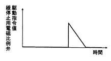
急停止時挙動予測部60cでは、急停止指令が行われると仮定し、急停止指令時の作業機械1の挙動を予測する。現在の姿勢情報と速度推定部60bの速度推定結果と急停止モデルとから、急停止指令が行われてから駆動アクチュエータが完全に停止するまでの位置軌跡、速度軌跡、加速度軌跡を算出する。急停止モデルとしては、例えば、急停止時の速度軌跡をモデル化し、その速度軌跡から位置軌跡および加速度軌跡を算出する方法が考えられる。あらかじめ急停止指令時の速度軌跡をモデル化し、時刻tにおいて急停止指令が行われたときの時刻(操作レバー開放時刻)からt秒後のシリンダ速度をVstop(t,t)として与えたとき、t秒後のシリンダ長lstop(t,t)とシリンダ加速度astop(t,t)は、急停止開始時のシリンダ、長lstop(t,0)を用いて以下の式(4)で算出できる。
Sudden stop behavior prediction unit The sudden stop behavior prediction unit 60c assumes that a sudden stop command is issued, and predicts the behavior of the work machine 1 at the time of the sudden stop command. Based on the current posture information, the speed estimation result of the speed estimation unit 60b, and the sudden stop model, the position locus, speed locus, and acceleration locus from when the sudden stop command is issued until the drive actuator completely stops are calculated. As the sudden stop model, for example, a method of modeling a speed trajectory at the time of sudden stop and calculating a position trajectory and an acceleration trajectory from the speed trajectory can be considered. Previously modeled abrupt stop command when the speed trajectory, given cylinder speed of t e seconds after the time (operation lever open time) at which the abrupt stop command is performed V stop (t, t e) as at time t Then, the cylinder length l stop (t, t e ) and cylinder acceleration a stop (t, t e ) after te seconds are expressed as follows using the cylinder at the start of sudden stop, the length l stop (t, 0): (4).

Figure 2017008501
Figure 2017008501

実時間で急停止時挙動予測を行うためには、急停止時の速度軌跡を簡易なモデルでモデル化すると良い。急停止時の速度軌跡の簡易モデルとしては、1次遅れ系や多次遅れ系や多項式関数が考えられる。本実施形態の安定化制御では緩停止を行うため、急停止指令に加え、緩停止指令時の挙動についても同様のモデル化を行う。   In order to predict the sudden stop behavior in real time, it is better to model the speed trajectory during the sudden stop with a simple model. As a simple model of the speed trajectory at the time of sudden stop, a first-order lag system, a multi-order lag system, or a polynomial function can be considered. In the stabilization control of the present embodiment, since a slow stop is performed, the same modeling is performed for the behavior at the time of the slow stop command in addition to the sudden stop command.

安定性判定部60dは、この急停止時挙動予測部60cにおいて算出された急停止時軌跡を用いて、急停止過程におけるZMP軌跡を算出し、安定性を判定する。   The stability determination unit 60d calculates the ZMP locus in the sudden stop process using the sudden stop locus calculated by the sudden stop behavior prediction unit 60c, and determines the stability.

具体的には、安定性判定部60dでは、まず、急停止時挙動予測部60cの予測結果を用いて、作業機械1の主要構成部材の重心の位置ベクトル軌跡と加速度ベクトル軌跡を算出する。そして、式(1)から導出される以下の式(5)および式(6)を用いてZMP軌跡を算出する。   Specifically, the stability determination unit 60d first calculates the position vector locus and acceleration vector locus of the center of gravity of the main components of the work machine 1 using the prediction result of the sudden stop behavior prediction unit 60c. Then, the ZMP trajectory is calculated using the following equations (5) and (6) derived from the equation (1).

Figure 2017008501
Figure 2017008501

Figure 2017008501
Figure 2017008501

上式のrに各主要構成部材の重心の急停止時位置ベクトル軌跡を、r”に急停止時加速度ベクトル軌跡を代入することにより、急停止時のZMP軌跡を算出することができる。   By substituting the position vector locus of the center of gravity of each main component at the sudden stop and the acceleration vector locus at the time of sudden stop into r ″, the ZMP locus at the time of sudden stop can be calculated.

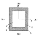
次に、算出された急停止時のZMP軌跡を用いて急停止時の安定性を判定する。前述のようにZMPが作業機械1と地表面29とで形成する支持多角形Lの十分内側の領域に存在する場合には、作業機械1は不安定になる可能性はほとんどなく、安定に作業を行うことができる。走行体2が地表面29に成立している場合、支持多角形Lは、走行体2の平面形状と等しい。したがって、走行体2の平面形状が矩形の場合、支持多角形Lは図6に示すように矩形となる。より具体的には、走行体2としてクローラを有している場合の支持多角形Lは左右のスプロケットの中心点を結んだ線を前方境界線、左右のアイドラの中心点を結んだ線を後方境界線、左右それぞれのトラックリンク外側端を左右の境界線とした四角形である。なお、前方および後方の境界は、最も前方の下部ローラおよび最も後方の下部ローラを接地点としても良い。   Next, the stability at the time of sudden stop is determined using the calculated ZMP locus at the time of sudden stop. As described above, when the ZMP exists in a region sufficiently inside the support polygon L formed by the work machine 1 and the ground surface 29, the work machine 1 is hardly likely to become unstable and can be operated stably. It can be performed. When the traveling body 2 is formed on the ground surface 29, the support polygon L is equal to the planar shape of the traveling body 2. Therefore, when the planar shape of the traveling body 2 is rectangular, the support polygon L is rectangular as shown in FIG. More specifically, the support polygon L in the case of having a crawler as the traveling body 2 is a front boundary line connecting the center points of the left and right sprockets, and a rear line connecting the center points of the left and right idlers. The boundary line is a quadrangle with the left and right track link outer ends as the left and right boundary lines. Note that the front and rear boundaries may use the frontmost lower roller and the rearmost lower roller as a ground point.

安定性判定部60dでは、支持多角形Lを作業機械1が不安定となる可能性が十分に低い通常領域Jと不安定となる可能性の高い安定警告領域Nとに分け、ZMPがいずれの領域にあるかを判定することによって安定性を判定する。通常、領域Jと安定警告領域Nとの境界Kは、安全率に従って決定される比率に応じて支持多角形Lを中心点側に縮小した多角形、あるいは、安全率に従って決定される長さだけ支持多角形Lを内側に移動した多角形に設定される。安定性判定部60dでは、急停止時のZMP軌跡上の全ての点が通常領域Jにある場合に、安定性判定結果を「安定」として出力する。一方、急停止時のZMP軌跡が安定警告領域Nに侵入する場合、すなわち、急停止過程のいずれかの時点でZMPが安定警告領域Nに侵入する場合には、判定結果を「不安定」として出力する。   In the stability determination unit 60d, the support polygon L is divided into a normal region J where the possibility that the work machine 1 becomes unstable is sufficiently low and a stability warning region N where the possibility that the work machine 1 becomes unstable is high. Stability is determined by determining if it is in the region. Normally, the boundary K between the region J and the stability warning region N is a polygon obtained by reducing the support polygon L toward the center point according to the ratio determined according to the safety factor, or the length determined according to the safety factor. The support polygon L is set to a polygon moved inward. The stability determination unit 60d outputs the stability determination result as “stable” when all the points on the ZMP locus at the time of sudden stop are in the normal region J. On the other hand, if the ZMP trajectory at the time of sudden stop enters the stable warning region N, that is, if ZMP enters the stable warning region N at any point in the sudden stop process, the determination result is “unstable” Output.

・動作制限決定部
動作制限決定部60hでは、安定性判定部60dの判定結果を元に動作制限の要否を判定し、動作制限指令を算出する。本実施形態の安定化制御装置190では、作業機械1を安定に保つために緩停止と動作速度制限を行う。したがって、動作制限決定部60hは、動作制限指令として緩停止指令と動作速度制限指令を算出し、指令値生成部60iに出力する。
Operation Restriction Determination Unit The operation restriction determination unit 60h determines whether or not operation restriction is necessary based on the determination result of the stability determination unit 60d, and calculates an operation restriction command. In the stabilization control apparatus 190 of this embodiment, in order to keep the work machine 1 stable, a slow stop and an operation speed limit are performed. Therefore, the operation restriction determination unit 60h calculates a slow stop command and an operation speed restriction command as the operation restriction command, and outputs them to the command value generation unit 60i.

前述のように、本実施形態の安定化制御演算部60aでは、挙動予測および安定性評価を必要に応じて複数回繰り返すことにより、安定化に必要な動作制限を算出する。動作制限および繰り返し演算の要否判定方法について、図7を用いて説明する。   As described above, the stabilization control calculation unit 60a according to the present embodiment calculates an operation restriction necessary for stabilization by repeating behavior prediction and stability evaluation a plurality of times as necessary. A method for determining the necessity of operation restriction and repetitive calculation will be described with reference to FIG.

図7において、第一回目の試行においては、速度推定部60bの推定結果および急停止モデルを用いる設定とし(ステップS71)、挙動予測(ステップS72)および安定性の判定を行う(ステップS73)。   In FIG. 7, in the first trial, the estimation result of the speed estimation unit 60b and the sudden stop model are set (step S71), behavior prediction (step S72), and stability determination are performed (step S73).

ステップS73における判定結果が「安定」であった場合には、動作制限を行わない(ステップS73のOK)。この場合には、「緩停止なし」、「動作速度制限ゲイン=1」を出力する(ステップS710)。   If the determination result in step S73 is “stable”, the operation is not limited (OK in step S73). In this case, “no slow stop” and “operation speed limit gain = 1” are output (step S710).

一方、安定性判定部60dの判定結果が「不安定」であった場合(ステップS73のNG)は、急停止モデルに代えて緩停止モデルを用いる設定とし(ステップS74)、設定変更後での挙動予測(ステップS75)および安定性判定を行う(ステップS76)。   On the other hand, when the determination result of the stability determination unit 60d is “unstable” (NG in step S73), the setting is to use the slow stop model instead of the sudden stop model (step S74). Behavior prediction (step S75) and stability determination are performed (step S76).

ステップS76における安定性判定部60dの判定結果が「安定」であった場合(ステップS76のOK)は、動作速度制限ゲインを1とし、緩停止のみを行うように動作制限指令を行う(ステップS711)。   When the determination result of the stability determination unit 60d in step S76 is “stable” (OK in step S76), the operation speed limit gain is set to 1 and an operation limit command is issued so that only a slow stop is performed (step S711). ).

一方、安定性判定部60dの判定結果が「不安定」であった場合(ステップS76のNG)は、速度推定値に動作速度制限ゲインα(<1)を乗じたものと、緩停止モデルとを用いる設定とし(ステップS77)、設定変更後での挙動予測(ステップS78)および安定性判定(ステップS79)を行う。   On the other hand, when the determination result of the stability determination unit 60d is “unstable” (NG in step S76), the speed estimated value is multiplied by the operating speed limit gain α (<1), the slow stop model, (Step S77), behavior prediction after changing the setting (step S78) and stability determination (step S79) are performed.

安定性判定部60dの判定結果が「安定」であった場合(ステップS79のOK)は、緩停止指令および動作速度制限ゲインαの動作速度制限を行うように動作制限指令を行う(ステップS712)。   When the determination result of the stability determination unit 60d is “stable” (OK in step S79), an operation restriction command is issued so as to perform a slow stop command and an operation speed limit of the operation speed limit gain α (step S712). .

一方、安定性判定部60dの判定結果が「不安定」であった場合(ステップS79のNG)は、動作速度制限ゲインαを徐々に小さくし、安定性判定部60dの判定結果が「安定」となるまで、挙動予測(ステップS78)と安定性判定(ステップS79)を繰り返す。   On the other hand, when the determination result of the stability determination unit 60d is “unstable” (NG in step S79), the operation speed limit gain α is gradually decreased, and the determination result of the stability determination unit 60d is “stable”. Until it becomes, behavior prediction (step S78) and stability determination (step S79) are repeated.

なお、上記では、緩停止指令時に選択される停止特性が一通りである場合を例にとって説明したが、複数の停止特性を設定し、安定状態に応じて緩停止の程度を変更するように構成しでも良い。緩停止の程度を表す指標としては、停止に要する時間(停止時間)、停止に要する距離(制動距離)、減速加速度、単位時間当たりのパイロット圧の低下量(パイロット圧変化率)等が例として挙げられ、複数の設定を設ける場合には、あらかじめそれぞれの設定のおいて満たすべき停止特性を定める。また、動作制限決定部60hでは、全ての緩停止設定において安定性判定結果が不安定となった場合に初めて動作速度を制限するように動作制限指令を算出する。   In the above description, the case where there is one stop characteristic selected at the time of the slow stop command has been described as an example, but a configuration in which a plurality of stop characteristics are set and the degree of slow stop is changed in accordance with the stable state. You can do it. Examples of indices indicating the degree of slow stop include time required for stop (stop time), distance required for stop (braking distance), deceleration acceleration, pilot pressure decrease per unit time (pilot pressure change rate), etc. For example, when a plurality of settings are provided, stop characteristics to be satisfied in each setting are determined in advance. In addition, the operation restriction determination unit 60h calculates an operation restriction command so as to restrict the operation speed only when the stability determination result becomes unstable in all the slow stop settings.

<指令値生成部>
指令値生成部60iは、安定化制御演算部60aから出力された緩停止指令および動作速度制限指令に基づいて、パイロット圧補正部200の駆動指令値を生成し、演算装置60の出力部60yに出力する。
<Command value generator>
The command value generation unit 60i generates a drive command value for the pilot pressure correction unit 200 based on the slow stop command and the operation speed limit command output from the stabilization control calculation unit 60a, and outputs the drive command value to the output unit 60y of the calculation device 60. Output.

より具体的には、指令値生成部60iは、緩停止指令値から停止特性変更部210の駆動指令値を、動作速度制限ゲインから動作速度制限部240の駆動指令値を算出する。本実施形態の安定化制御装置190では、図5Aに示したように、ブーム伸長、ブーム縮小、アーム伸長、アーム縮小のそれぞれのパイロット油路に、各停止特性変更部211,212,213,214および各動作速度制限部241,242,243,244が設けられており、指令値生成部60iは、各停止特性変更部211,212,213,214および各動作速度制限部241,242,243,244に対して駆動指令値を算出する。以下では、ブーム伸長パイロット圧油の補正を例にとって、ブーム伸長停止特性変更部211およびブーム伸長動作速度制限部241の駆動指令値の算出方法を説明する。まず、ブーム伸長停止特性変更部211の駆動指令値の算出方法について説明する。   More specifically, the command value generation unit 60i calculates the drive command value of the stop characteristic changing unit 210 from the slow stop command value, and the drive command value of the operation speed limit unit 240 from the operation speed limit gain. In the stabilization control device 190 of the present embodiment, as shown in FIG. 5A, each stop characteristic changing unit 211, 212, 213, 214 is provided in each of the pilot oil passages of boom extension, boom reduction, arm extension, and arm reduction. And operation speed limiting units 241, 242, 243, and 244 are provided, and the command value generating unit 60i includes each stop characteristic changing unit 211, 212, 213, 214 and each operation speed limiting unit 241, 242, 243. A drive command value is calculated for 244. Hereinafter, a method for calculating the drive command values of the boom extension stop characteristic changing unit 211 and the boom extension operation speed limiting unit 241 will be described using the correction of the boom extension pilot pressure oil as an example. First, a method for calculating the drive command value of the boom extension / stop characteristic changing unit 211 will be described.

図5Bを用いて説明したように、本実施形態の停止特性変更部211は、緩停止用電磁比例弁221と緩停止用高圧選択部231とから構成されている。停止特性変更部211では、急減速操作あるいは停止操作が行われた場合に、動作制限決定部60hから出力された緩停止指令を満たすパイロット圧油を生成するように緩停止用電磁比例弁221を駆動することにより、駆動アクチュエータを緩やかに停止させる。同様に、停止特性変更部212は、緩停止用電磁比例弁222と緩停止用高圧選択部232とから構成され、動作速度制限部242は速度制限用電磁比例弁252から構成される。緩停止用電磁比例弁222および速度制限用電磁比例弁252は後述する演算装置60から出力される指令信号により駆動される。   As described with reference to FIG. 5B, the stop characteristic changing unit 211 of the present embodiment includes the slow stop electromagnetic proportional valve 221 and the slow stop high pressure selection unit 231. The stop characteristic changing unit 211 sets the slow stop electromagnetic proportional valve 221 so as to generate pilot pressure oil that satisfies the slow stop command output from the operation limit determining unit 60h when a sudden deceleration operation or a stop operation is performed. By driving, the drive actuator is gently stopped. Similarly, the stop characteristic changing unit 212 includes a slow stop electromagnetic proportional valve 222 and a slow stop high pressure selection unit 232, and the operation speed limit unit 242 includes a speed limit electromagnetic proportional valve 252. The slow stop electromagnetic proportional valve 222 and the speed limiting electromagnetic proportional valve 252 are driven by a command signal output from the arithmetic unit 60 described later.

緩停止を行うための駆動指令の算出方法は、緩停止時の停止特性の設定方法により種々考えられるが、以下では、停止特性としてブーム流量制御弁111に供給するパイロット圧油の圧力の変化率を指令し、レバー操作パイロット圧を図4Aに示す補正曲線を用いて補正する場合を例にとって説明する。   Various methods for calculating the drive command for performing the slow stop are conceivable depending on the method for setting the stop characteristic at the time of the slow stop. Will be described as an example in which the lever operation pilot pressure is corrected using the correction curve shown in FIG. 4A.

前述のように、ブーム流量制御弁111に供給するパイロット圧油の圧力と駆動アクチュエータの動作速度は比例の関係にある。このため、減速および停止操作時のレバー操作パイロット圧の変化率が指令値よりも大きい場合は指令された停止特性よりも速やかに減速し、指令値よりも小さい場合は、指令された停止特性よりも緩やかに減速する。本実施形態の安定化制御装置190において動作制限を行う必要があるのは、指令された停止特性よりも速やかに停止する場合である。   As described above, the pressure of the pilot pressure oil supplied to the boom flow rate control valve 111 and the operation speed of the drive actuator are in a proportional relationship. Therefore, if the rate of change of the lever operation pilot pressure during deceleration and stop operation is greater than the command value, the speed will decelerate more quickly than the commanded stop characteristic. Also slow down slowly. In the stabilization control device 190 of the present embodiment, it is necessary to limit the operation when stopping more quickly than the commanded stop characteristic.

このために、指令値生成部60iでは、まず、レバー操作パイロット圧の変化率と変化率指令値を比較する。そして、レバー操作パイロット圧の変化率が変化率指令値よりも大きい場合には、図4Aに示す補正曲線を用いて、パイロット圧が変化率指令値を満たす単調減少となるように補正する。つまり、停止特性変更部211の出力するパイロット圧油の圧力を以下の式(7)のようにする。   For this purpose, the command value generation unit 60i first compares the change rate of the lever operation pilot pressure with the change rate command value. When the change rate of the lever operation pilot pressure is larger than the change rate command value, correction is performed using the correction curve shown in FIG. 4A so that the pilot pressure decreases monotonously to satisfy the change rate command value. That is, the pressure of the pilot pressure oil output from the stop characteristic changing unit 211 is expressed by the following equation (7).

Figure 2017008501
Figure 2017008501

ここで、Plev(t)は時刻tにおけるレバー操作パイロット圧、P211(t)は時刻tにおいて停止特性変更部211の出力するパイロット圧油の圧力、kはパイロット圧変化率指令値である。停止特性変更部211においてレバー操作パイロット圧油を補正せずに出力する場合には、緩停止用電磁比例弁221を駆動する必要はなく、レバー操作パイロット圧の変化率が変化率指令値よりも大きい場合のみ、式(7)で算出される圧力の緩停止パイロット圧油を生成するように緩停止用電磁比例弁221を駆動すれば良い。したがって、緩停止用電磁比例弁221の指令圧は以下の式(8)のように算出する。 Here, P lev (t) is the lever operation pilot pressure at time t, P 211 (t) is the pressure of the pilot pressure oil output from the stop characteristic changing unit 211 at time t, and k is the pilot pressure change rate command value. . When the stop characteristic changing unit 211 outputs the lever operation pilot pressure oil without correcting it, it is not necessary to drive the slow stop electromagnetic proportional valve 221, and the change rate of the lever operation pilot pressure is higher than the change rate command value. Only when it is large, the slow stop electromagnetic proportional valve 221 may be driven so as to generate the slow stop pilot pressure oil having the pressure calculated by the equation (7). Accordingly, the command pressure of the slow stop electromagnetic proportional valve 221 is calculated as in the following equation (8).

Figure 2017008501
Figure 2017008501

ここで、P221c(t)は時刻tにおける緩停止用電磁比例弁221の指令圧である。 Here, P 221c (t) is a command pressure of the slow stop electromagnetic proportional valve 221 at time t.

緩停止用電磁比例弁221の出力する圧油の圧力は指令信号の大きさによって決定され、指令信号と圧力との関係は、弁の出力特性として、例えば、図8Aのように与えられる。緩停止用電磁比例弁221への駆動指令値は、式(8)で算出される指令圧と緩停止用電磁比例弁221の出力特性を用いて決定する。例えば、図8Bに示した補正を行う場合の緩停止用電磁比例弁221への駆動指令値は図8Cのように算出される。   The pressure of the pressure oil output from the slow stop electromagnetic proportional valve 221 is determined by the magnitude of the command signal, and the relationship between the command signal and the pressure is given, for example, as shown in FIG. The drive command value for the slow stop electromagnetic proportional valve 221 is determined using the command pressure calculated by the equation (8) and the output characteristics of the slow stop electromagnetic proportional valve 221. For example, the drive command value to the slow stop electromagnetic proportional valve 221 when the correction shown in FIG. 8B is performed is calculated as shown in FIG. 8C.

本実施形態の安定化制御装置190では、ブームシリンダ11およびアームシリンダ13に対して動作制限を行うため、ブーム伸長緩停止用電磁比例弁221、ブーム縮小緩停止用電磁比例弁222、アーム伸長緩停止用電磁比例弁、アーム縮小緩停止用電磁比例弁の4つの緩停止用電磁比例弁が備えられている。指令値生成部60iは、それぞれの緩停止用電磁比例弁に対して、それぞれの対応するレバー操作パイロット圧を用いて駆動指令値を算出する。   In the stabilization control device 190 of the present embodiment, the boom cylinder 11 and the arm cylinder 13 are limited in operation. Therefore, the boom expansion / slow stop electromagnetic proportional valve 221, the boom reduction / slow stop electromagnetic proportional valve 222, and the arm extension / slow Four proportional solenoid valves for slow stop are provided: a solenoid proportional valve for stop and an electromagnetic proportional valve for arm reduction slow stop. The command value generation unit 60i calculates a drive command value for each slow stop electromagnetic proportional valve using the corresponding lever operation pilot pressure.

次に、ブーム伸長動作速度制限部241の駆動指令値の算出方法について説明する。前述のように、本実施形態では動作速度制限部241として速度制限用電磁比例弁251を備えており、速度制限用電磁比例弁251への駆動指令値によって、ブーム流量制御弁111のパイロットポートに供給されるパイロット圧油の上限圧が決定される。駆動アクチュエータの動作速度はパイロット圧に概ね比例するため、動作制限決定部60hから出力された動作速度制限ゲインに基づいて速度制限用電磁比例弁251の駆動指令値を算出すればよい。   Next, a method for calculating the drive command value of the boom extension operation speed limiter 241 will be described. As described above, in the present embodiment, the speed limiting electromagnetic proportional valve 251 is provided as the operation speed limiting unit 241, and the boom flow control valve 111 is connected to the pilot port according to the drive command value to the speed limiting electromagnetic proportional valve 251. An upper limit pressure of the supplied pilot pressure oil is determined. Since the operation speed of the drive actuator is approximately proportional to the pilot pressure, the drive command value for the speed limiting electromagnetic proportional valve 251 may be calculated based on the operation speed limit gain output from the operation limit determination unit 60h.

具体的には、速度制限用電磁比例弁251に対して最大の駆動指令を与えた場合には、停止特性変更部211から速度制限用電磁比例弁251に入力されるパイロット圧油の圧力によらず、入力された圧油が補正されることなく出力される。したがって、動作速度制限ゲインが1である場合は、速度制限用電磁比例弁251に対し、最大の駆動指令を行う。   Specifically, when the maximum drive command is given to the speed limiting electromagnetic proportional valve 251, it depends on the pressure of the pilot pressure oil input to the speed limiting electromagnetic proportional valve 251 from the stop characteristic changing unit 211. Instead, the input pressure oil is output without being corrected. Therefore, when the operation speed limit gain is 1, the maximum drive command is issued to the speed limiting electromagnetic proportional valve 251.

一方、動作速度制限ゲインが1未満の場合は、レバー操作パイロット圧を減ずる必要があるため、動作速度制限ゲインに応じて、レバー操作パイロット圧を減圧するように駆動指令を行う。ここで、動作速度制限ゲインは、レバー操作によって指令された動作速度からの必要な減速率を表しており、レバー操作パイロット圧に対して行うべき減圧率と考えて良い。つまり、速度制限用電磁比例弁251から出力される補正パイロット圧油の圧力を、レバー操作パイロット圧に動作速度制限ゲインを乗じた圧力以下とするように、速度制限用電磁比例弁251を駆動すれば良い。したがって、速度制限用電磁比例弁251の指令圧は以下のように算出される。   On the other hand, when the operating speed limit gain is less than 1, it is necessary to reduce the lever operation pilot pressure. Therefore, a drive command is issued to reduce the lever operation pilot pressure according to the operating speed limit gain. Here, the operation speed limit gain represents a necessary deceleration rate from the operation speed commanded by the lever operation, and may be considered as a pressure reduction rate to be performed with respect to the lever operation pilot pressure. In other words, the speed limiting electromagnetic proportional valve 251 is driven so that the pressure of the corrected pilot pressure oil output from the speed limiting electromagnetic proportional valve 251 is equal to or lower than the pressure obtained by multiplying the lever operation pilot pressure by the operating speed limiting gain. It ’s fine. Therefore, the command pressure of the speed limiting electromagnetic proportional valve 251 is calculated as follows.

Figure 2017008501
Figure 2017008501

ここで、P251c(t)は時刻tにおける速度制限用電磁比例弁251の指令圧であり、PMAXは速度制限用電磁比例弁251の定格圧力である。 Here, P 251c (t) is the command pressure of the speed limiting electromagnetic proportional valve 251 at time t, and P MAX is the rated pressure of the speed limiting electromagnetic proportional valve 251.

緩停止用電磁比例弁221の場合と同様、速度制限用電磁比例弁251の出力する圧油の圧力は指令信号の大きさによって決定され、指令信号と圧力との関係は、弁の出力特性として、例えば、図8Aのように与えられる。速度制限用電磁比例弁251への駆動指令値は、式(9)で算出される指令圧と速度制限用電磁比例弁251の出力特性を用いて決定する。例えば、図8Bに示した補正を行う場合の速度制限用電磁比例弁251への駆動指令値は図8Dのように算出される。   As in the case of the slow stop electromagnetic proportional valve 221, the pressure of the pressure oil output from the speed limiting electromagnetic proportional valve 251 is determined by the magnitude of the command signal, and the relationship between the command signal and the pressure is expressed as the output characteristics of the valve. For example, as shown in FIG. 8A. The drive command value to the speed limiting electromagnetic proportional valve 251 is determined using the command pressure calculated by the equation (9) and the output characteristic of the speed limiting electromagnetic proportional valve 251. For example, the drive command value to the speed limiting electromagnetic proportional valve 251 when the correction shown in FIG. 8B is performed is calculated as shown in FIG. 8D.

本実施形態の安定化制御装置190では、ブームシリンダ11およびアームシリンダ13に対して動作制限を行うため、ブーム伸長速度制限用電磁比例弁251、ブーム縮小速度制限用電磁比例弁252、アーム伸長速度制限用電磁比例弁(図示せず)、アーム縮小速度制限用電磁比例弁(図示せず)の4つの速度制限用電磁比例弁が備えられており、指令値生成部60iは、それぞれの電磁比例弁に対して駆動指令値を算出する。駆動指令値は、それぞれ対応するレバー操作パイロット圧から式(9)を用いて算出する。このようにレバー操作パイロット圧に基づいて駆動指令を算出することによって、作業状態によってパイロット圧と動作速度との関係が変化する場合であっても、速度制限用電磁比例弁251によって、安定化制御演算部60aから指令された動作速度制限を確実に実現することができる。   In the stabilization control device 190 of the present embodiment, the boom cylinder 11 and the arm cylinder 13 are limited in operation, so that the boom extension speed limiting electromagnetic proportional valve 251, the boom reduction speed limiting electromagnetic proportional valve 252, and the arm extension speed are limited. Four speed limiting electromagnetic proportional valves, a limiting electromagnetic proportional valve (not shown) and an arm reduction speed limiting electromagnetic proportional valve (not shown), are provided. A drive command value is calculated for the valve. The drive command value is calculated using Equation (9) from the corresponding lever operation pilot pressure. By calculating the drive command based on the lever operation pilot pressure in this way, even if the relationship between the pilot pressure and the operating speed changes depending on the work state, the speed limiting electromagnetic proportional valve 251 can be used for stabilization control. It is possible to reliably realize the operation speed limit commanded from the calculation unit 60a.

<作用>
以上で説明したように、本実施形態によれば、作業機械1に対して無理な操作や誤った操作を行った場合にも、作業機械1を安定に保つために必要な動作制限が行われ、安定性を損なうことなく、作業を継続させることができる。また、本実施形態では、動作制限が必要な場合のみ、パイロット圧補正部200における補正を行い、動作制限の必要のない場合には従来と同様に比例減圧弁群から出力されるパイロット圧油を用いて駆動アクチュエータを駆動する構成を有しており、従来の操作性を損なうことなく、動作制限を行うことができる。したがって、本実施形態の安定化制御装置190により、操作性および安定性の高い作業機械を提供することができる。
<Action>
As described above, according to the present embodiment, even when an unreasonable operation or an erroneous operation is performed on the work machine 1, the operation restriction necessary for keeping the work machine 1 stable is performed. The work can be continued without losing stability. Further, in the present embodiment, the pilot pressure correction unit 200 performs correction only when the operation restriction is necessary, and when the operation restriction is not necessary, the pilot pressure oil output from the proportional pressure reducing valve group is used as in the conventional case. The drive actuator is configured to be used, and the operation can be limited without impairing the conventional operability. Therefore, the stabilization control device 190 of the present embodiment can provide a work machine with high operability and stability.

<第1の実施形態の変更例>
<センサ構成>
上記の実施形態では、姿勢検出部49として作業機械1の傾きを検出するための姿勢センサ3bを設ける例を示したが、作業中に作業機械1の傾きが変化しない場合には、作業機械1の傾きを一定値とし、姿勢センサ3bを設けない構成としても良い。
<Modified example of the first embodiment>
<Sensor configuration>
In the above-described embodiment, an example in which the posture sensor 3b for detecting the tilt of the work machine 1 is provided as the posture detection unit 49 has been described. However, when the tilt of the work machine 1 does not change during the work, the work machine 1 The inclination may be a constant value and the posture sensor 3b may not be provided.

また、上記の実施形態では、レバー操作量検出部50aとして、ブーム伸長操作量センサ51と、ブーム縮小操作量センサ52と、アーム伸長操作量センサ53と、アーム縮小操作量センサ54と、アタッチメント伸長操作量センサ55と、アタッチメント縮小操作量センサ56と、右旋回操作量センサ57と、左旋回操作量センサ58とを設ける例を示したが、動作制限を適用する駆動アクチュエータへのレバー操作にコいてのみセンサを設ける構成としても良い。例えば、ブームシリンダ11およびアームシリンダ13に対して動作制限を行う場合には、アタッチメント伸長操作量センサ55と、アタッチメント縮小操作量センサ56と、右旋回操作量センサ57と、左旋回操作量センサ58を省略する構成としても良い。   In the above embodiment, as the lever operation amount detection unit 50a, the boom extension operation amount sensor 51, the boom reduction operation amount sensor 52, the arm extension operation amount sensor 53, the arm reduction operation amount sensor 54, and the attachment extension are provided. Although an example in which the operation amount sensor 55, the attachment reduction operation amount sensor 56, the right turn operation amount sensor 57, and the left turn operation amount sensor 58 are provided is shown, the lever operation to the drive actuator to which the operation restriction is applied is shown. It is good also as a structure which provides a sensor only in the direction. For example, when the operation is restricted for the boom cylinder 11 and the arm cylinder 13, an attachment extension operation amount sensor 55, an attachment reduction operation amount sensor 56, a right turn operation amount sensor 57, and a left turn operation amount sensor 58 may be omitted.

<対象とする駆動アクチュエータ>
上記の実施形態では、ブームシリンダ11、およびアームシリンダ13に対して動作制限を行う場合を例にとって説明したが、ブームシリンダ11、アームシリンダ13に加えて、旋回モータ7やアタッチメントシリンダ、15に対して動作制限を行うように構成しても良い。
<Target drive actuator>
In the above embodiment, the case where the operation is restricted with respect to the boom cylinder 11 and the arm cylinder 13 has been described as an example. However, in addition to the boom cylinder 11 and the arm cylinder 13, the swing motor 7 and the attachment cylinder 15 The operation may be limited.

この場合には、ブーム伸長、ブーム縮小アーム伸長、アーム縮小の各パイロット油路に加え、右旋回、左旋回、アタッチメント伸長、アタッチメント縮小の各パイロット油路に各パイロット圧補正部を設けて、指令値生成部60iにおいて、ブーム伸長、ブーム縮小、アーム伸長、アーム縮小の各パイロット圧補正部201,202,203,204への駆動指令に加えて、右旋回、左旋回、アタッチメント伸長、アタッチメント縮小の各パイロット圧補正部への駆動指令を生成するように構成すればよい。   In this case, in addition to the pilot oil passages for boom extension, boom reduction arm extension, and arm reduction, each pilot pressure correction unit is provided in each pilot oil passage for right turn, left turn, attachment extension, and attachment reduction, In the command value generation unit 60i, in addition to the drive commands to the pilot pressure correction units 201, 202, 203, and 204 for boom extension, boom reduction, arm extension, and arm reduction, right turn, left turn, attachment extension, and attachment What is necessary is just to comprise so that the drive command to each pilot pressure correction | amendment part of reduction | decrease may be produced | generated.

<動作速度制限部の変更例>
以下では、パイロット圧補正部の変更例について、ブーム伸長パイロット圧油の補正を例にとって説明する。
<Example of changing the operating speed limiter>
Below, the example of a change of a pilot pressure correction | amendment part is demonstrated taking the correction | amendment of boom extension pilot pressure oil as an example.

上記の実施形態では、ブーム伸長動作速度制限部241として、常時閉式の特性を持つ速度制限用電磁比例弁251を用いる例を示したが、速度制限用電磁比例弁251は、ブーム流量制御弁111のブーム伸長側パイロットポート111eに供給するパイロット圧油の圧力を指令圧まで減圧する機能を有すれば良く、必ずしも上記の特性を持つ弁である必要はない。例えば、速度制限用電磁比例弁251の他の例としては、図9Aに示すような常時開式の特性を持つ電磁比例弁が挙げられる。   In the above embodiment, an example in which the speed limiting electromagnetic proportional valve 251 having normally closed characteristics is used as the boom extension operation speed limiting unit 241 has been described. However, the speed limiting electromagnetic proportional valve 251 is the boom flow control valve 111. It is only necessary to have a function of reducing the pressure of the pilot pressure oil supplied to the boom extension side pilot port 111e to the command pressure, and the valve does not necessarily have the above-described characteristics. For example, another example of the speed limiting electromagnetic proportional valve 251 is an electromagnetic proportional valve having a normally open characteristic as shown in FIG. 9A.

具体的には、図9Aに示すように、速度制限用電磁比例弁251を常時開式の電磁比例弁とする。この場合、ソレノイド251dが励磁されていない時には、第二ポート251bと第三ポート251cとを連通する弁路が全開、第一ポート251aが全閉となり、停止特性変更部211からのパイロット圧油が減圧されることなくブーム流量制御弁111のブーム伸長側パイロットポート111eに供給される。これに対し、演算装置60からの指令信号によってソレノイド251dが励磁されると、第二ポート251bと第三ポート251cとを連通する弁路が閉じる方向に駆動され、停止特性変更部211からのパイロット圧油が指令圧まで減圧される。また、ソレノイド251dへの指令信号が最大である場合には、第一ポート251aと第三ポート251cとを連通する弁路が全開、第二ポート251bが全閉となる。このとき、ブーム流量制御弁111へのパイロット圧油の供給は停止され、ブーム流量制御弁111のパイロットポートに接続されるパイロット油路の圧油は作動油タンク103に排出される。   Specifically, as shown in FIG. 9A, the speed limiting electromagnetic proportional valve 251 is a normally open electromagnetic proportional valve. In this case, when the solenoid 251d is not energized, the valve path communicating the second port 251b and the third port 251c is fully opened, the first port 251a is fully closed, and the pilot pressure oil from the stop characteristic changing unit 211 is The pressure is supplied to the boom extension side pilot port 111e of the boom flow control valve 111 without being depressurized. On the other hand, when the solenoid 251d is excited by a command signal from the arithmetic unit 60, the valve path communicating the second port 251b and the third port 251c is driven in the closing direction, and the pilot from the stop characteristic changing unit 211 is driven. Pressure oil is reduced to the command pressure. Further, when the command signal to the solenoid 251d is the maximum, the valve path communicating the first port 251a and the third port 251c is fully opened, and the second port 251b is fully closed. At this time, the supply of pilot pressure oil to the boom flow control valve 111 is stopped, and the pressure oil in the pilot oil passage connected to the pilot port of the boom flow control valve 111 is discharged to the hydraulic oil tank 103.

このような特性を有する電磁比例弁を用いる場合には、指令値生成部60iにおいて、動作制限決定部60hから出力される動作速度制限ゲインが1の場合はソレノイド251dを非励磁状態とし、動作速度制限ゲインが1未満の場合は速度制限用電磁比例弁251の指令圧を式(9)によって算出される圧力とするように駆動指令を行う。   When an electromagnetic proportional valve having such characteristics is used, in the command value generation unit 60i, when the operation speed limit gain output from the operation limit determination unit 60h is 1, the solenoid 251d is brought into a non-excitation state, and the operation speed is increased. When the limit gain is less than 1, a drive command is issued so that the command pressure of the speed limiting electromagnetic proportional valve 251 is the pressure calculated by the equation (9).

速度制限用電磁比例弁251として常時閉式の電磁比例弁を用いる場合と常時開式を用いる場合の特徴を説明する。   The characteristics when a normally closed electromagnetic proportional valve is used as the speed limiting electromagnetic proportional valve 251 and when the normally open type is used will be described.

図5Bに示すような常時閉式とする場合には、演算装置60や、演算装置60と速度制限用電磁比例弁251とを接続する電気回路に不具合が生じ、ソレノイド251dへの指令信号が与えられなかった場合に、ソレノイド251dが非励磁状態となり、ブーム流量制御弁111へのパイロット圧油の供給が停止され、駆動アクチュエータは停止状態となる。一方、速度制限用電磁比例弁251を常時開式とすると、ソレノイド251dへの指令信号が与えられなかった場合には、停止特性変更部211の出力するパイロット圧油がブーム流量制御弁111へ供給されるため、動作速度が制限されないまま、駆動アクチュエータの動作が継続される。   In the case of the normally closed type as shown in FIG. 5B, a malfunction occurs in the arithmetic device 60 or in the electric circuit connecting the arithmetic device 60 and the speed limiting electromagnetic proportional valve 251, and a command signal is given to the solenoid 251d. If not, the solenoid 251d is de-energized, the supply of pilot pressure oil to the boom flow control valve 111 is stopped, and the drive actuator is stopped. On the other hand, if the speed limiting electromagnetic proportional valve 251 is normally opened, the pilot pressure oil output from the stop characteristic changing unit 211 is supplied to the boom flow control valve 111 when a command signal to the solenoid 251d is not given. Therefore, the operation of the drive actuator is continued without limiting the operation speed.

また、常時閉式の速度制限用電磁比例弁251を用いる場合には、動作速度制限部241において補正の必要がない時に、常に演算装置60から最大の指令信号を出力する必要があるが、常時開式を用いる場合には指令信号を零とすれば良く、必要な電流量は常時開式を用いるほうが少なくなる傾向がある。   When the normally-closed speed limiting electromagnetic proportional valve 251 is used, it is necessary to always output the maximum command signal from the arithmetic unit 60 when the operation speed limiting unit 241 does not require correction. When the equation is used, the command signal may be set to zero, and the required amount of current tends to be smaller when the normally open method is used.

したがって、安全性の観点では常時閉式が、利便性、電流量の観点では常時開式が優れている。いずれの特性の電磁比例弁を用いるかは、適用する作業機械において求められる安全性、利便性、および演算装置の性能を考慮して決定すれば良い。   Therefore, the normally closed type is superior from the viewpoint of safety, and the normally open type is superior from the viewpoint of convenience and current amount. Which characteristic of the electromagnetic proportional valve is used may be determined in consideration of safety, convenience, and performance of the arithmetic unit required for the working machine to be applied.

また、上記の実施形態では、動作速度制限部241として速度制限用電磁比例弁251を設ける例を示したが、動作速度制限部241は、ブーム流量制御弁111に供給するパイロット圧油の圧力を指令圧まで減圧する機能を有すればよく、電磁比例弁以外の他の構成を用いても良い。他の構成例として、速度制限用電磁比例弁251に代えて速度制限用電磁比例リリーフ弁261を備えている構成が考えられる。動作速度制限部として速度制限用電磁比例リリーフ弁261を備えている場合のブーム伸長パイロット圧補正部201の概略構成を図9Bに示した。   In the above-described embodiment, an example in which the speed limiting electromagnetic proportional valve 251 is provided as the operating speed limiting unit 241 has been described. However, the operating speed limiting unit 241 controls the pressure of the pilot pressure oil supplied to the boom flow rate control valve 111. What is necessary is just to have the function to reduce to command pressure, and you may use structures other than an electromagnetic proportional valve. As another configuration example, a configuration in which a speed limiting electromagnetic proportional relief valve 261 is provided instead of the speed limiting electromagnetic proportional valve 251 can be considered. FIG. 9B shows a schematic configuration of the boom extension pilot pressure correcting unit 201 when the speed limiting electromagnetic proportional relief valve 261 is provided as the operating speed limiting unit.

具体的には、図9Bに示すように、速度制限用電磁比例リリーフ弁261は、入力ポート261aとタンクポート261bとソレノイド261cとを備えており、入力ポート261aは停止特性変更部211とブーム流量制御弁111のブーム伸長側パイロットポート111eとを接続するパイロット油路に、タンクポート261bは作動油タンク103にそれぞれ接続される。ソレノイド261cは演算装置60からの指令信号によって励磁され、その指令信号の大きさによって、速度制限用電磁比例リリーフ弁261の設定圧が決定される。   Specifically, as shown in FIG. 9B, the speed limiting electromagnetic proportional relief valve 261 includes an input port 261a, a tank port 261b, and a solenoid 261c, and the input port 261a includes the stop characteristic changing unit 211 and the boom flow rate. The tank port 261 b is connected to the hydraulic oil tank 103 in a pilot oil passage that connects the boom extension side pilot port 111 e of the control valve 111. The solenoid 261c is excited by a command signal from the arithmetic unit 60, and the set pressure of the speed limiting electromagnetic proportional relief valve 261 is determined by the magnitude of the command signal.

速度制限用電磁比例リリーフ弁261では、入力ポート261a側の圧力が設定圧よりも高い場合には、入力ポート261aとタンクポート261bとを連通する弁路が開き、入力ポート261aに接続される油路の圧油が作動油タンク103に排出される。これにより、入力ポート261a側の圧力、すなわち、停止特性変更部211からブーム流量制御弁111のブーム伸長側パイロットポート111eへ供給されるパイロット圧油の圧力は、設定圧以下に保たれる。また、入力ポート261aとタンクポート261bとを連通する弁路が全閉である場合には、パイロット圧油は速度制限用電磁比例リリーフ弁261によって補正されない。したがって、速度制限用電磁比例リリーフ弁261の設定圧を、安定化制御演算部60aによって指令された動作速度制限を満たす上限圧とすることによって、速度制限用電磁比例弁251を用いる場合と同様に、動作速度制限を行うことができる。   In the speed limiting electromagnetic proportional relief valve 261, when the pressure on the input port 261a side is higher than the set pressure, the valve path that connects the input port 261a and the tank port 261b is opened, and the oil connected to the input port 261a. The pressure oil in the road is discharged to the hydraulic oil tank 103. As a result, the pressure on the input port 261a side, that is, the pressure of the pilot pressure oil supplied from the stop characteristic changing unit 211 to the boom extension side pilot port 111e of the boom flow rate control valve 111 is kept below the set pressure. Further, when the valve path communicating the input port 261a and the tank port 261b is fully closed, the pilot pressure oil is not corrected by the speed limiting electromagnetic proportional relief valve 261. Therefore, by setting the set pressure of the speed limiting electromagnetic proportional relief valve 261 to an upper limit pressure that satisfies the operating speed limit commanded by the stabilization control calculation unit 60a, the same as when the speed limiting electromagnetic proportional valve 251 is used. The operation speed can be limited.

動作速度制限部241として速度制限用電磁比例リリーフ弁261を用いる場合には、指令値生成部60iにおいて、動作制限決定部60hから出力される動作速度制限ゲインが1の場合は、設定圧が最大となるように駆動指令値を算出すれば良い。また、動作速度制限ゲインが1未満の場合は、設定圧が式(9)によって算出される指令圧となるように駆動指令値を算出すれば良い。   When the speed limiting electromagnetic proportional relief valve 261 is used as the operating speed limiting unit 241, when the operating speed limiting gain output from the operating limit determining unit 60h is 1 in the command value generating unit 60i, the set pressure is maximum. The drive command value may be calculated so that If the operation speed limit gain is less than 1, the drive command value may be calculated so that the set pressure becomes the command pressure calculated by the equation (9).

<緩停止用電磁比例弁の駆動指令>
上記の実施形態では、指令値生成部60iにおいて、レバー操作パイロット圧が指令された停止特性よりも急激に低下する場合のみ、緩停止用電磁比例弁221へ駆動指令を行う例を示した。そして、上記の例では、レバー操作パイロット圧が低下しない場合や、指令された停止特性よりも緩やかに低下する場合には指令信号を零とした。
<Drive command for solenoid valve for slow stop>
In the embodiment described above, the command value generation unit 60i has shown the example in which the drive command is issued to the slow stop electromagnetic proportional valve 221 only when the lever operation pilot pressure is drastically lower than the commanded stop characteristic. In the above example, the command signal is set to zero when the lever operation pilot pressure does not decrease or when the lever operation pilot pressure decreases more slowly than the commanded stop characteristic.

しかし、一般に電磁比例電磁弁へ駆動信号を行ってから出力される圧油が指令圧になるまでには、ある程度の遅れがある。緩停止用電磁比例弁221の応答性が低い場合には、指令圧までの立ち上がりのタイムラグにより、圧力が一時的に低下し、正確に緩停止が行われない可能性がある。このような問題を回避するために、緩停止用電磁比例弁221に対し、常に待機信号を与えるように構成しても良い。この場合の待機信号の大きさは、緩停止パイロット圧がレバー操作パイロット圧を超えない大きさとし、緩停止用電磁比例弁221の応答性を考慮して決定すればよい。   However, in general, there is a certain amount of delay until the output hydraulic pressure becomes the command pressure after the drive signal is sent to the electromagnetic proportional solenoid valve. When the responsiveness of the slow stop electromagnetic proportional valve 221 is low, there is a possibility that the pressure temporarily decreases due to the rise time lag to the command pressure, and the slow stop is not accurately performed. In order to avoid such a problem, it may be configured to always give a standby signal to the slow stop electromagnetic proportional valve 221. The magnitude of the standby signal in this case is determined so that the slow stop pilot pressure does not exceed the lever operation pilot pressure, and the response of the slow stop electromagnetic proportional valve 221 is taken into consideration.

<動作速度制限指令算出方法の変更例>
上記の実施形態では、動作制限決定部60hにおいて動作速度制限ゲインを算出し、指令値生成部60iにおいて、動作速度制限ゲインとレバー操作パイロット圧とを用いて速度制限用電磁比例弁251の駆動指令値を算出する例を示した。このような構成とすることにより、パイロット圧と動作速度との関係が作業状態によって変化する場合においても、適切に動作速度制限を行うことができる。
<Example of change in operation speed limit command calculation method>
In the above embodiment, the operation limit determination unit 60h calculates the operation speed limit gain, and the command value generation unit 60i uses the operation speed limit gain and the lever operation pilot pressure to drive the speed limit electromagnetic proportional valve 251. An example of calculating the value is shown. By adopting such a configuration, even when the relationship between the pilot pressure and the operation speed changes depending on the working state, the operation speed can be appropriately limited.

一方、作業状態によらず、パイロット圧から動作速度が一意に決定される場合には、以下のように構成しても良い。動作制限決定部60hにおいて、動作速度制限ゲインを算出する代わりに、動作速度の上限値を算出する。また、指令値生成部60iにおいて、パイロット圧と動作速度との関係式を用いて、動作速度上限値からパイロット圧上限値を算出し、このパイロット圧上限値を速度制限用電磁比例弁251の指令圧として、駆動指令を行う。   On the other hand, when the operation speed is uniquely determined from the pilot pressure regardless of the working state, the following configuration may be used. In the operation restriction determination unit 60h, instead of calculating the operation speed restriction gain, the upper limit value of the operation speed is calculated. In addition, the command value generating unit 60i calculates a pilot pressure upper limit value from the operating speed upper limit value using a relational expression between the pilot pressure and the operating speed, and uses the pilot pressure upper limit value as a command for the speed limiting electromagnetic proportional valve 251. A drive command is issued as the pressure.

<第2の実施形態>
本発明の作業機械の第2の実施形態を図10を用いて説明する。
<Second Embodiment>
A second embodiment of the work machine of the present invention will be described with reference to FIG.

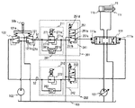
本実施形態では、停止特性変更部210として、第1の実施形態で用いた緩停止用電磁比例弁221,222を含む緩停止用電磁比例弁群と緩停止用高圧選択部231,232を含む緩停止用高圧選択部群とに代えて、緩停止用電磁比例圧力保持弁271,272を含む電磁比例圧力保持弁群と緩停止用逆止弁281,282を含む逆止弁群とを用いる。以下では、図10を参照し、主に第1の実施形態との相違点を説明する。なお、図1乃至図9Bと同じ構成には同一の符号を示し、説明は省略する。以下の実施形態においても同様とする。   In the present embodiment, the stop characteristic changing unit 210 includes the slow stop electromagnetic proportional valve group including the slow stop electromagnetic proportional valves 221 and 222 used in the first embodiment and the slow stop high pressure selectors 231 and 232. Instead of the slow stop high pressure selector group, an electromagnetic proportional pressure hold valve group including the slow stop electromagnetic proportional pressure hold valves 271 and 272 and a check valve group including the slow stop check valves 281 and 282 are used. . Below, with reference to FIG. 10, a difference with 1st Embodiment is mainly demonstrated. In addition, the same code | symbol is shown to the same structure as FIG. 1 thru | or 9B, and description is abbreviate | omitted. The same applies to the following embodiments.

<パイロット圧補正部>
本実施形態のパイロット圧補正部200は、第1の実施形態と同様、停止特性変更部210と動作速度制限部240とから構成される。安定化制御演算に基づく動作制限をブームシリンダ11およびアームシリンダ13に対して適用するために、作業機械1には、パイロット圧補正部200として、ブーム伸長パイロット圧補正部201、ブーム縮小パイロット圧補正部202、アーム伸長パイロット圧補正部(図示せず)、アーム縮小パイロット圧補正部(図示せず)が設けられる。各パイロット圧補正部201,202の構成はいずれについても同様の構成であり、ブーム伸長パイロット圧補正部201はブーム伸長停止特性変更部211とブーム伸長動作速度制限部241を備え、ブーム縮小パイロット圧補正部202はブーム縮小停止特性変更部212とブーム縮小動作速度制限部242を備えている。図示しないアーム伸長パイロット圧補正部も同様にアーム伸長停止特性変更部とアーム伸長動作速度制限部を備え、アーム縮小パイロット圧補正部もアーム縮小停止特性変更部とアーム縮小動作速度制限部を備えている。本実施形態の各動作速度制限部241,242…の構成は第1の実施形態と同様である。以下では、ブーム伸長パイロット圧油の補正を例にとり、ブーム伸長停止特性変更部211についてのみ説明する。
<Pilot pressure correction unit>
As in the first embodiment, the pilot pressure correction unit 200 according to the present embodiment includes a stop characteristic changing unit 210 and an operation speed limiting unit 240. In order to apply the operation restriction based on the stabilization control calculation to the boom cylinder 11 and the arm cylinder 13, the work machine 1 includes a boom extension pilot pressure correction unit 201, a boom reduction pilot pressure correction as the pilot pressure correction unit 200. A unit 202, an arm extension pilot pressure correction unit (not shown), and an arm reduction pilot pressure correction unit (not shown) are provided. Each of the pilot pressure correction units 201 and 202 has the same configuration, and the boom extension pilot pressure correction unit 201 includes a boom extension stop characteristic change unit 211 and a boom extension operation speed limit unit 241, and includes a boom reduction pilot pressure. The correction unit 202 includes a boom reduction stop characteristic changing unit 212 and a boom reduction operation speed limiting unit 242. Similarly, an arm extension pilot pressure correction unit (not shown) includes an arm extension stop characteristic change unit and an arm extension operation speed limit unit, and an arm reduction pilot pressure correction unit also includes an arm reduction stop characteristic change unit and an arm reduction operation speed limit unit. Yes. The configuration of each of the operation speed limiting units 241, 242,... According to this embodiment is the same as that of the first embodiment. In the following, only the boom extension stop characteristic changing unit 211 will be described by taking correction of boom extension pilot pressure oil as an example.

<停止特性変更部>
本実施形態のブーム伸長停止特性変更部211は、電磁比例圧力保持弁群としての緩停止用電磁比例圧力保持弁271と逆止弁群としての緩停止用逆止弁281とから構成される。
<Stop characteristic change part>
The boom extension stop characteristic changing unit 211 of the present embodiment includes a slow stop electromagnetic proportional pressure holding valve 271 as an electromagnetic proportional pressure holding valve group and a slow stop check valve 281 as a check valve group.

緩停止用逆止弁281は、圧油の流れ方向を制限する弁であり、緩停止用電磁比例圧力保持弁271は、パイロット圧油の作動油タンク103への排出を制御する弁である。緩停止用逆止弁281および緩停止用電磁比例圧力保持弁271は、比例減圧弁121と動作速度制限部241とを接続する油路に並列に設けられる。すなわち、比例減圧弁121と動作速度制限部241との間には、緩停止用逆止弁281を備えたパイロット油路と緩停止用電磁比例圧力保持弁271を備えたパイロット油路とが設けられており、圧油はいずれかの油路を流通する。以下では緩停止用逆止弁281と緩停止用電磁比例圧力保持弁271の詳細を説明する。   The slow stop check valve 281 is a valve that limits the flow direction of the pressure oil, and the slow stop electromagnetic proportional pressure holding valve 271 is a valve that controls the discharge of the pilot pressure oil to the hydraulic oil tank 103. The slow stop check valve 281 and the slow stop electromagnetic proportional pressure holding valve 271 are provided in parallel to the oil passage connecting the proportional pressure reducing valve 121 and the operation speed limiter 241. That is, between the proportional pressure reducing valve 121 and the operation speed limiter 241, there is provided a pilot oil passage provided with a slow stop check valve 281 and a pilot oil passage provided with a slow stop electromagnetic proportional pressure holding valve 271. The pressure oil flows through one of the oil passages. Details of the slow stop check valve 281 and the slow stop electromagnetic proportional pressure holding valve 271 will be described below.

緩停止用逆止弁281は、圧油の流れ方向を制限する弁であって、入力ポート281aおよび出力ポート281bを備えている。緩停止用逆止弁281の入力ポート281aには比例減圧弁121の第三ポート121cが、出力ポート281bには動作速度制限部241を構成する速度制限用電磁比例弁251の第二ポート251bが接続され、比例減圧弁121から動作速度制限部241への圧油の流れを自由流れとし、動作速度制限部241から比例減圧弁121への圧油の流れを遮断する。したがって、圧油は、比例減圧弁121から動作速度制限部241へ流通する場合には、緩停止用逆止弁281を備えたパイロット油路を通り、動作速度制限部241から比例減圧弁121へ流通する場合には緩停止用電磁比例圧力保持弁271を備えたパイロット油路を流通する。   The slow stop check valve 281 is a valve that limits the flow direction of pressure oil, and includes an input port 281a and an output port 281b. The input port 281a of the slow stop check valve 281 has a third port 121c of the proportional pressure reducing valve 121, and the output port 281b has a second port 251b of the speed limiting electromagnetic proportional valve 251 constituting the operating speed limiting unit 241. Connected, the flow of pressure oil from the proportional pressure reducing valve 121 to the operation speed limiting unit 241 is a free flow, and the flow of pressure oil from the operation speed limiting unit 241 to the proportional pressure reducing valve 121 is blocked. Accordingly, when the pressure oil flows from the proportional pressure reducing valve 121 to the operation speed limiting unit 241, the pressure oil passes through the pilot oil passage provided with the slow stop check valve 281, and then moves from the operation speed limiting unit 241 to the proportional pressure reducing valve 121. When it circulates, it circulates through a pilot oil passage provided with an electromagnetic proportional pressure holding valve 271 for slow stop.

前述のように、パイロット油路の圧油の流れの方向は、操作レバー50の操作状態によって決定される。操作レバー50を、比例減圧弁121から出力されるレバー操作パイロット圧を増大させる方向に操作した場合には、比例減圧弁121からパイロット油路へパイロット圧油が供給され、レバー操作パイロット圧を低下させる方向に操作した場合には、パイロット油路の圧油が比例減圧弁121の第一ポート121aと第三ポート121cとを連通する弁路を流通して作動油タンク103に排出される。したがって、本実施形態の停止特性変更部211は、レバー操作パイロット圧を増大させる場合の圧油の供給を自由流れとし、レバー操作パイロット圧を低下させる場合、すなわち、駆動アクチュエータを減速させる場合の圧油の流通を緩停止用電磁比例圧力保持弁271よって制御する構成である。   As described above, the direction of the pressure oil flow in the pilot oil passage is determined by the operation state of the operation lever 50. When the operation lever 50 is operated in a direction to increase the lever operation pilot pressure output from the proportional pressure reducing valve 121, the pilot pressure oil is supplied from the proportional pressure reducing valve 121 to the pilot oil passage, and the lever operation pilot pressure is reduced. When operated in such a direction, the pressure oil in the pilot oil passage flows through a valve passage communicating the first port 121a and the third port 121c of the proportional pressure reducing valve 121 and is discharged to the hydraulic oil tank 103. Therefore, the stop characteristic changing unit 211 of the present embodiment sets the pressure oil supply when increasing the lever operation pilot pressure as a free flow, and reduces the lever operation pilot pressure, that is, the pressure when decelerating the drive actuator. This is a configuration in which the flow of oil is controlled by an electromagnetic proportional pressure holding valve 271 for slow stop.

緩停止用電磁比例圧力保持弁271は、第一ポート271a、第二ポート271b、およびソレノイド271cを備えており、第一ポート271aは速度制限用電磁比例弁251の第二ポート251bと、第二ポート271bは比例減圧弁121の第三ポート121cとそれぞれ接続される。ソレノイド271cは演算装置60からの指令信号によって励磁され、その指令信号の大きさによって、緩停止用電磁比例圧力保持弁271の保持圧が決定される。   The slow stop electromagnetic proportional pressure holding valve 271 includes a first port 271a, a second port 271b, and a solenoid 271c. The first port 271a includes a second port 251b of the speed limiting electromagnetic proportional valve 251 and a second port 251b. The port 271 b is connected to the third port 121 c of the proportional pressure reducing valve 121. The solenoid 271c is excited by a command signal from the arithmetic unit 60, and the holding pressure of the slow stop electromagnetic proportional pressure holding valve 271 is determined by the magnitude of the command signal.

緩停止用電磁比例圧力保持弁271では、第一ポート271a側の圧力が保持圧よりも高い場合には、第一ポート271aと第二ポート271bとを連通する弁路が開き、第一ポート271aから第二ポート271bへ圧油が供給される。前述のように、圧油が緩停止用電磁比例圧力保持弁271を通過するのは、動作速度制限部241から比例減圧弁121へ圧油が流通する場合のみであり、この時、比例減圧弁121に供給された圧油は、比例減圧弁121の第一ポート121aと第三ポート121cとを連通する弁路を流通して作動油タンク103へ排出される。つまり、緩停止用電磁比例圧力保持弁271は、緩停止用電磁比例圧力保持弁271と動作速度制限部241とを連結するパイロット油路の圧油の圧力が保持圧よりも高い場合には圧油を作動油タンク103に排出し、保持圧よりも低い場合には作動油タンク103への排出を遮断する。これによって、パイロット圧油の圧力を保持圧に保つ。   In the slow stop electromagnetic proportional pressure holding valve 271, when the pressure on the first port 271a side is higher than the holding pressure, the valve path communicating the first port 271a and the second port 271b is opened, and the first port 271a is opened. Pressure oil is supplied to the second port 271b. As described above, the pressure oil passes through the slow stop electromagnetic proportional pressure holding valve 271 only when the pressure oil flows from the operation speed limiter 241 to the proportional pressure reducing valve 121. At this time, the proportional pressure reducing valve The pressure oil supplied to 121 is discharged to the hydraulic oil tank 103 through a valve path that connects the first port 121 a and the third port 121 c of the proportional pressure reducing valve 121. In other words, the slow stop electromagnetic proportional pressure holding valve 271 is a pressure when the pressure oil pressure in the pilot oil passage connecting the slow stop electromagnetic proportional pressure holding valve 271 and the operating speed limiter 241 is higher than the holding pressure. The oil is discharged to the hydraulic oil tank 103, and when it is lower than the holding pressure, the discharge to the hydraulic oil tank 103 is shut off. As a result, the pressure of the pilot pressure oil is maintained at the holding pressure.

ソレノイド271cが励磁されていない場合には、パイロット油路の圧油の圧力によらず、第一ポート271aと第二ポート271bとを連通する弁路が全開となり、作動油タンク103への排出が自由に行われる。   When the solenoid 271c is not energized, the valve path communicating the first port 271a and the second port 271b is fully opened regardless of the pressure oil pressure in the pilot oil path, and the discharge to the hydraulic oil tank 103 is prevented. Done freely.

一方、緩停止用電磁比例圧力保持弁271に対して最大の駆動指令を行うと、第一ポート271aと第二ポート271bとを連通する弁路が閉じ状態となり、駆動アクチュエータを減速あるいは停止させるように操作レバー50を操作した場合においても、パイロット油路の圧油が作動油タンク103に排出されない。このとき、動作速度制限部241に供給されるパイロット圧油の圧力はレバー操作によって比例減圧弁121から出力されたレバー操作パイロット圧の最大圧に保たれ、駆動アクチュエータは減速されることなく動作を継続する。   On the other hand, when the maximum drive command is issued to the slow stop electromagnetic proportional pressure holding valve 271, the valve path communicating the first port 271 a and the second port 271 b is closed, so that the drive actuator is decelerated or stopped. Even when the operation lever 50 is operated, the pressure oil in the pilot oil passage is not discharged to the hydraulic oil tank 103. At this time, the pressure of the pilot pressure oil supplied to the operating speed limiting unit 241 is maintained at the maximum lever operating pilot pressure output from the proportional pressure reducing valve 121 by the lever operation, and the drive actuator operates without being decelerated. continue.

このように、緩停止用電磁比例圧力保持弁271の保持圧を緩やかに低下させることにより、パイロット圧油の圧力を緩やかに低下させ、駆動アクチュエータを緩やかに減速させることができる。したがって、緩停止用電磁比例圧力保持弁271の保持圧を、安定化制御演算部60aによって指令された緩停止の停止特性を満たす圧力とすることによって、緩停止用電磁比例弁221を用いる場合と同様に、指令された緩停止を行うことができる。   In this way, by gradually reducing the holding pressure of the slow stop electromagnetic proportional pressure holding valve 271, the pressure of the pilot pressure oil can be gradually reduced, and the drive actuator can be slowly decelerated. Accordingly, the slow stop electromagnetic proportional valve 221 is used by setting the holding pressure of the slow stop electromagnetic proportional pressure holding valve 271 to a pressure that satisfies the stop characteristics of the slow stop commanded by the stabilization control calculation unit 60a. Similarly, the commanded slow stop can be performed.

<演算装置>
演算装置60は、第1の実施形態と同様に、作業機械1の各部に取り付けられた各センサからの信号が入力される入力部60x、入力部60xに入力される信号を受けて所定の演算を行う演算部60z、演算部60zからの出力信号を受けてパイロット圧補正部200への駆動指令を出力する出力部60yを備えている。演算部60zは、作業機械1を安定に保つための動作制限を算出する安定化制御演算部60aと、パイロット圧補正部200への駆動指令を算出する指令値生成部60iとから構成される。
<Calculation device>
As in the first embodiment, the calculation device 60 receives a signal from each sensor attached to each part of the work machine 1 and receives a signal input to the input unit 60x, and performs a predetermined calculation. And an output unit 60y that receives an output signal from the calculation unit 60z and outputs a drive command to the pilot pressure correction unit 200. The calculation unit 60z includes a stabilization control calculation unit 60a that calculates an operation limit for keeping the work machine 1 stable, and a command value generation unit 60i that calculates a drive command to the pilot pressure correction unit 200.

第2の実施形態の演算装置60において、第1の実施形態と異なるのは、指令値生成部60iにおける停止特性変更部210への駆動指令の算出方法のみである。以下では、ブーム伸長パイロット圧油の補正を例にとり、指令値生成部60iにおける緩停止用電磁比例圧力保持弁271への駆動指令の算出方法についてのみ説明する。   In the arithmetic device 60 of the second embodiment, the only difference from the first embodiment is the method of calculating the drive command to the stop characteristic changing unit 210 in the command value generating unit 60i. Hereinafter, taking a correction of boom extension pilot pressure oil as an example, only a method of calculating a drive command to the slow stop electromagnetic proportional pressure holding valve 271 in the command value generation unit 60i will be described.

<指令値生成部>
本実施形態のブーム伸長停止特性変更部211は、緩停止用逆止弁281と緩停止用電磁比例圧力保持弁271とから構成されており、停止特性変更部211の出力するパイロット圧油が動作制限決定部60hから出力された緩停止指令を満たす圧力となるように、緩停止用電磁比例圧力保持弁271を駆動することにより、駆動アクチュエータを緩やかに停止させる。
<Command value generator>
The boom extension stop characteristic changing unit 211 of the present embodiment includes a slow stop check valve 281 and a slow stop electromagnetic proportional pressure holding valve 271, and pilot pressure oil output from the stop characteristic changing unit 211 operates. The drive actuator is gently stopped by driving the slow stop electromagnetic proportional pressure holding valve 271 so that the pressure satisfies the slow stop command output from the limit determining unit 60h.

以下では、第1の実施形態と同様に、停止特性としてブーム流量制御弁111に供給するパイロット圧油の圧力の変化率を指令し、レバー操作パイロット圧を図4Aに示す補正曲線を用いて補正する場合を例にとって、緩停止用電磁比例圧力保持弁271への駆動指令値の算出方法を説明する。   Hereinafter, as in the first embodiment, the change rate of the pressure of the pilot pressure oil supplied to the boom flow control valve 111 is commanded as a stop characteristic, and the lever operation pilot pressure is corrected using the correction curve shown in FIG. 4A. As an example, a method for calculating a drive command value for the slow proportional electromagnetic proportional pressure holding valve 271 will be described.

本実施形態において指令された緩停止を行うためには、停止特性変更部211の出力圧を式(7)で算出される圧力とする必要がある。緩停止用電磁比例圧力保持弁271を圧油が流通しない場合や、緩停止用電磁比例圧力保持弁271において出力圧を補正する必要がない場合には、緩停止用電磁比例圧力保持弁271を駆動する必要はない。つまり、レバー操作パイロット圧の変化率が変化率指令値よりも大きい場合のみ、保持圧を式(7)で算出される圧力とするように駆動すればよい。したがって、緩停止用電磁比例圧力保持弁271の保持圧は、第1の実施形態の緩停止用電磁比例弁221の指令圧と同様に式(8)を用いて算出される圧力とすればよい。また、緩停止用電磁比例圧力保持弁271の保持圧はソレノイド271cに与えられる指令信号の大きさによって決定され、指令信号と圧力との関係は、弁の出力特性としてあらかじめ与えられる。したがって、緩停止用電磁比例圧力保持弁271への駆動指令値は式(8)で算出される保持圧と、弁の出力特性とを用いて算出する。   In order to perform the commanded slow stop in the present embodiment, it is necessary to set the output pressure of the stop characteristic changing unit 211 to a pressure calculated by Expression (7). When pressure oil does not flow through the slow stop electromagnetic proportional pressure holding valve 271 or when there is no need to correct the output pressure in the slow stop electromagnetic proportional pressure hold valve 271, the slow stop electromagnetic proportional pressure hold valve 271 is set. There is no need to drive. That is, only when the change rate of the lever operation pilot pressure is larger than the change rate command value, the holding pressure may be driven so as to be the pressure calculated by the equation (7). Therefore, the holding pressure of the slow stop electromagnetic proportional pressure holding valve 271 may be a pressure calculated using the equation (8) in the same manner as the command pressure of the slow stop electromagnetic proportional valve 221 of the first embodiment. . The holding pressure of the slow stop electromagnetic proportional pressure holding valve 271 is determined by the magnitude of the command signal given to the solenoid 271c, and the relationship between the command signal and the pressure is given in advance as the output characteristic of the valve. Therefore, the drive command value for the slow stop electromagnetic proportional pressure holding valve 271 is calculated using the holding pressure calculated by the equation (8) and the output characteristics of the valve.

<特長>
本実施形態のような態様の停止特性変更部211を用いると、定常的な動作指令操作時や増速操作時等、レバー操作パイロット圧を低下させないような操作時には、レバーパイロット圧油は緩停止用逆止弁281を備えた油路を流通し、補正されることなく出力される。また、安定化制御演算部60aにより指令された緩停止の停止特性よりも緩やかに停止させるような操作が行われた場合にも、緩停止用電磁比例圧力保持弁271による補正は行われない。
<Features>
When the stop characteristic changing unit 211 having a mode as in the present embodiment is used, the lever pilot pressure oil is slowly stopped during operations that do not decrease the lever operation pilot pressure, such as during a steady operation command operation or a speed increase operation. The oil is circulated through the oil passage provided with the check valve 281 and is output without being corrected. In addition, even when an operation for stopping more slowly than the stop characteristic of the slow stop commanded by the stabilization control calculation unit 60a is performed, the correction by the slow stop electromagnetic proportional pressure holding valve 271 is not performed.

一方、レバー操作パイロット圧が安定化制御演算部60aから指令された緩停止の停止特性よりも急激に低下する場合には、緩停止用電磁比例圧力保持弁271は、停止特性変更部211の出力圧が指令された緩停止の停止特性を満たす圧力となるように駆動され、緩停止用電磁比例圧力保持弁271によってパイロット圧油の作動油タンク103への排出が制御され、指令された停止特性の緩停止が実現される。   On the other hand, when the lever operation pilot pressure is suddenly lower than the stop characteristic of the slow stop commanded from the stabilization control calculation unit 60a, the slow stop electromagnetic proportional pressure holding valve 271 outputs the output of the stop characteristic changing unit 211. The pressure is driven so as to satisfy the commanded slow stop stop characteristic, and the discharge of pilot pressure oil to the hydraulic oil tank 103 is controlled by the slow stop electromagnetic proportional pressure holding valve 271. The commanded stop characteristic A slow stop is realized.

したがって、本実施形態の停止特性変更部211は第1の実施形態の停止特性変更部211と同様、レバー操作パイロット圧油の圧力が安定化制御演算部60aから指令された緩停止指令を満たさない場合のみ補正を行う構成であり、従来の操作性に影響を与えることなく、動作制限を行うことができる。   Therefore, the stop characteristic changing unit 211 of the present embodiment does not satisfy the slow stop command instructed by the stabilization control calculation unit 60a in the same manner as the stop characteristic changing unit 211 of the first embodiment. The correction is performed only in the case, and the operation can be restricted without affecting the conventional operability.

また、本実施形態の停止特性変更部211は、緩停止用逆止弁281により、比例減圧弁121からブーム流量制御弁111へのパイロット圧油の流れを自由流れとしていることから、緩停止用電磁比例圧力保持弁271は、ソレノイド271cの駆動状態によらず、駆動アクチュエータを駆動する方向の圧油の流通に影響を及ぼさない。   In addition, the stop characteristic changing unit 211 of the present embodiment makes the flow of the pilot pressure oil from the proportional pressure reducing valve 121 to the boom flow rate control valve 111 free flow by the slow stop check valve 281, so The electromagnetic proportional pressure holding valve 271 does not affect the flow of pressure oil in the direction in which the drive actuator is driven, regardless of the drive state of the solenoid 271c.

また、第1の実施形態の停止特性変更部211では、パイロットポンプ102の吐出する圧油を用いて緩停止パイロット圧を生成するのに対し、第2の実施形態の停止特性変更部211では、パイロット圧油の作動油タンクへの排出を制御することによってパイロット圧の低下を緩やかにして緩停止を実現する。つまり、第2の実施形態では、緩停止をパイロット油路へ新たに圧油を流入することなく実現しており、緩停止用電磁比例圧力保持弁271に対して誤った指令信号が与えられた場合にも、操作レバーが非操作状態において駆動アクチュエータが動作する恐れがなく、安全性が高い、との利点を有している。   Further, in the stop characteristic changing unit 211 of the first embodiment, the slow stop pilot pressure is generated using the pressure oil discharged from the pilot pump 102, whereas in the stop characteristic changing unit 211 of the second embodiment, By controlling the discharge of the pilot pressure oil to the hydraulic oil tank, the pilot pressure is gradually reduced to realize a slow stop. That is, in the second embodiment, the slow stop is realized without newly flowing pressure oil into the pilot oil passage, and an erroneous command signal is given to the slow stop electromagnetic proportional pressure holding valve 271. In this case, there is an advantage that the drive actuator does not operate when the operation lever is not operated, and the safety is high.

<第3の実施形態>
本発明の作業機械の第3の実施形態を図11を用いて説明する。
<Third Embodiment>
A third embodiment of the work machine of the present invention will be described with reference to FIG.

第2の実施形態では、停止特性変更部210として緩停止用逆止弁281,282を含む逆止弁群と緩停止用電磁比例圧力保持弁271,272を含む電磁比例圧力保持弁群を用いたが、本実施形態では緩停止用電磁比例圧力保持弁271,272を含む電磁比例圧力保持弁群に代えて、緩停止用電磁比例流量制御弁291,292電磁比例流量制御弁群を用いる。以下では、図11を参照し、主に第1および第2の実施形態との相違点を説明する。   In the second embodiment, a check valve group including slow stop check valves 281 and 282 and an electromagnetic proportional pressure holding valve group including slow stop electromagnetic proportional pressure holding valves 271 and 272 are used as the stop characteristic changing unit 210. However, in this embodiment, instead of the electromagnetic proportional pressure holding valve group including the slow stop electromagnetic proportional pressure holding valves 271,272, the slow stop electromagnetic proportional flow control valve 291,292 electromagnetic proportional flow control valve group is used. Below, with reference to FIG. 11, the difference with 1st and 2nd embodiment is mainly demonstrated.

<パイロット圧補正部>
本実施形態のパイロット圧補正部200は、第1および第2の実施形態と同様、停止特性変更部210と動作速度制限部240とから構成される。作業機械1には、パイロット圧補正部200として、ブーム伸長パイロット圧補正部201、ブーム縮小パイロット圧補正部202、アーム伸長パイロット圧補正部(図示せず)、アーム縮小パイロット圧補正部(図示せず)が設けられる。各パイロット圧補正部201,202の構成はいずれについても同様の構成であり、ブーム伸長パイロット圧補正部201はブーム伸長停止特性変更部211とブーム伸長動作速度制限部241を備え、ブーム縮小パイロット圧補正部202はブーム縮小停止特性変更部212とブーム縮小動作速度制限部242を備えている。図示しないアーム伸長パイロット圧補正部はアーム伸長停止特性変更部とアーム伸長動作速度制限部を備え、アーム縮小パイロット圧補正部もアーム縮小停止特性変更部とアーム縮小動作速度制限部を備えている。本実施形態の各動作速度制限部241,242…は第1の実施形態と同様である。以下では、ブーム伸長パイロット圧油の補正を例にとり、ブーム伸長停止特性変更部211についてのみ説明する。
<Pilot pressure correction unit>
Similar to the first and second embodiments, the pilot pressure correction unit 200 according to the present embodiment includes a stop characteristic changing unit 210 and an operation speed limiting unit 240. The work machine 1 includes a boom extension pilot pressure correction unit 201, a boom reduction pilot pressure correction unit 202, an arm extension pilot pressure correction unit (not shown), and an arm reduction pilot pressure correction unit (not shown) as the pilot pressure correction unit 200. Is provided. Each of the pilot pressure correction units 201 and 202 has the same configuration, and the boom extension pilot pressure correction unit 201 includes a boom extension stop characteristic changing unit 211 and a boom extension operation speed limiting unit 241, and includes a boom reduction pilot pressure. The correction unit 202 includes a boom reduction stop characteristic changing unit 212 and a boom reduction operation speed limiting unit 242. An arm extension pilot pressure correction unit (not shown) includes an arm extension stop characteristic change unit and an arm extension operation speed limit unit, and the arm reduction pilot pressure correction unit also includes an arm reduction stop characteristic change unit and an arm reduction operation speed limit unit. The operation speed limiting units 241, 242,... Of the present embodiment are the same as those of the first embodiment. In the following, only the boom extension stop characteristic changing unit 211 will be described by taking correction of boom extension pilot pressure oil as an example.

<停止特性変更部>
本実施形態のブーム伸長停止特性変更部211は、緩停止用逆止弁281と緩停止用電磁比例流量制御弁291とから構成される。緩停止用逆止弁281は、圧油の流れ方向を制限する弁であり、緩停止用電磁比例流量制御弁291は、パイロット油路の圧油の作動油タンク103への排出を制御する弁である。
<Stop characteristic change part>
The boom extension stop characteristic changing unit 211 of the present embodiment includes a slow stop check valve 281 and a slow stop electromagnetic proportional flow control valve 291. The slow stop check valve 281 is a valve that restricts the flow direction of the pressure oil, and the slow stop electromagnetic proportional flow control valve 291 is a valve that controls the discharge of the pressure oil in the pilot oil passage to the hydraulic oil tank 103. It is.

緩停止用電磁比例流量制御弁291は、第2の実施形態の緩停止用電磁比例圧力保持弁271の代わりに設けられる弁であり、緩停止用逆止弁281および緩停止用電磁比例流量制御弁291は、比例減圧弁121と動作速度制限部241とを接続する油路に並列に設けられる。   The slow stop electromagnetic proportional flow control valve 291 is a valve provided in place of the slow stop electromagnetic proportional pressure holding valve 271 of the second embodiment, and the slow stop check valve 281 and the slow stop electromagnetic proportional flow control. The valve 291 is provided in parallel to the oil passage that connects the proportional pressure reducing valve 121 and the operation speed limiter 241.

緩停止用逆止弁281の構成および作用は第2の実施形態と同様であり、本実施形態の停止特性変更部211は、レバー操作パイロット圧を増大させる場合の圧油の供給を自由流れとし、レバー操作パイロット圧を低下させる場合、すなわち、駆動アクチュエータを減速させる場合の圧油の流通を緩停止用電磁比例流量制御弁291よって制御する構成である。以下では、緩停止用電磁比例流量制御弁291の詳細を説明する。   The configuration and operation of the slow stop check valve 281 are the same as in the second embodiment, and the stop characteristic changing unit 211 of this embodiment sets the supply of pressure oil when increasing the lever operation pilot pressure to a free flow. When the lever operation pilot pressure is decreased, that is, when the drive actuator is decelerated, the flow of pressure oil is controlled by the slow stop electromagnetic proportional flow control valve 291. Hereinafter, details of the slow stop electromagnetic proportional flow control valve 291 will be described.

緩停止用電磁比例流量制御弁291は、第一ポート291a、第二ポート291b、およびソレノイド291cを備えており、第一ポート291aは速度制限用電磁比例弁251の第二ポート251bと、第二ポート291bは比例減圧弁121の第三ポート121cとそれぞれ接続される。第一ポート291aと第二ポート291bとを連通する弁路には開度を変更可能な絞り291dが設けられている。ソレノイド291cは演算装置60からの指令信号によって励磁され、その指令信号の大きさによって、絞り291dの開度が決定される。   The slow stop electromagnetic proportional flow control valve 291 includes a first port 291a, a second port 291b, and a solenoid 291c. The first port 291a includes a second port 251b of the speed limiting electromagnetic proportional valve 251 and a second port 251b. The port 291 b is connected to the third port 121 c of the proportional pressure reducing valve 121. A throttle 291d whose opening degree can be changed is provided in a valve path that communicates the first port 291a and the second port 291b. The solenoid 291c is excited by a command signal from the arithmetic unit 60, and the opening degree of the aperture 291d is determined by the magnitude of the command signal.

前述のように、圧油が緩停止用電磁比例流量制御弁291を通過するのは、動作速度制限部241から比例減圧弁121へ圧油が流通する場合のみであり、緩停止用電磁比例流量制御弁291は、駆動アクチュエータを減速させる操作が行われた場合のパイロット圧油の作動油タンク103への排出を制御する機能を持つ。絞り291dの開度によって第一ポート291aと第二ポート291bを連通する弁路を流通する圧油の流量が決定される。   As described above, the pressure oil passes through the slow stop electromagnetic proportional flow control valve 291 only when the pressure oil flows from the operation speed limiter 241 to the proportional pressure reducing valve 121, and the slow stop electromagnetic proportional flow rate. The control valve 291 has a function of controlling the discharge of pilot pressure oil to the hydraulic oil tank 103 when an operation for decelerating the drive actuator is performed. The flow rate of the pressure oil flowing through the valve path communicating with the first port 291a and the second port 291b is determined by the opening of the throttle 291d.

具体的には、絞り291dの開度が大きい場合には、弁路を流通できる流量が大きく、パイロット圧油は作動油タンク103へ速やかに排出される。それに伴い、パイロット圧油の圧力は速やかに低下する。絞り291dの開度を最大とした場合には、圧油の流通は自由流れとなる。一方、絞り291dの開度を小さくすると、第一ポート291aから第二ポート291bへ流通する圧油の流量が制限され、パイロット圧油の作動油タンク103への排出が緩やかになるため、パイロット圧油の圧力は緩やかに低下する。したがって、緩停止用電磁比例流量制御弁291の絞り291dの開度を適切に調整することにより、指令された停止特性の緩停止を行うことができる。   Specifically, when the opening of the throttle 291 d is large, the flow rate that can flow through the valve passage is large, and the pilot pressure oil is quickly discharged to the hydraulic oil tank 103. Along with this, the pressure of the pilot pressure oil quickly decreases. When the opening of the throttle 291d is maximized, the pressure oil flows freely. On the other hand, when the opening of the throttle 291d is reduced, the flow rate of the pressure oil flowing from the first port 291a to the second port 291b is limited, and the discharge of the pilot pressure oil to the hydraulic oil tank 103 becomes gentle. The oil pressure drops slowly. Accordingly, by appropriately adjusting the opening degree of the throttle 291d of the slow stop electromagnetic proportional flow control valve 291, it is possible to perform the slow stop with the commanded stop characteristic.

<演算装置>
演算装置60は、第1および第2の実施形態と同様に、作業機械1の各部に取り付けられた各センサからの信号が入力される入力部60x、入力部60xに入力される信号を受けて所定の演算を行う演算部60z、演算部60zからの出力信号を受けて、パイロット圧補正部200への駆動指令を出力する出力部60yを備えている。演算部60zは、作業機械1を安定に保つための動作制限を算出する安定化制御演算部60aと、パイロット圧補正部200への駆動指令を算出する指令値生成部60iとから構成される。
<Calculation device>
Similar to the first and second embodiments, the arithmetic device 60 receives an input unit 60x to which signals from respective sensors attached to each unit of the work machine 1 are input, and a signal input to the input unit 60x. A calculation unit 60z that performs a predetermined calculation and an output unit 60y that receives an output signal from the calculation unit 60z and outputs a drive command to the pilot pressure correction unit 200 are provided. The calculation unit 60z includes a stabilization control calculation unit 60a that calculates an operation limit for keeping the work machine 1 stable, and a command value generation unit 60i that calculates a drive command to the pilot pressure correction unit 200.

第3の実施形態の演算装置において、第1および第2の実施形態と異なるのは、指令値生成部60iにおける停止特性変更部210への駆動指令の算出方法のみである。以下では、ブーム伸長パイロット圧油の補正を例にとり、指令値生成部60iにおける緩停止用電磁比例流量制御弁291への駆動指令の算出方法について説明する。   In the arithmetic device of the third embodiment, the only difference from the first and second embodiments is the method of calculating the drive command to the stop characteristic changing unit 210 in the command value generating unit 60i. Hereinafter, taking a correction of boom extension pilot pressure oil as an example, a method of calculating a drive command to the slow stop electromagnetic proportional flow control valve 291 in the command value generation unit 60i will be described.

<指令値生成部>
本実施形態のブーム伸長停止特性変更部211は、緩停止用逆止弁281と緩停止用電磁比例流量制御弁291とから構成されており、緩停止用電磁比例流量制御弁291の内部に設けられた絞り291dの開度を適切に調整することによって、駆動アクチュエータの停止特性を所望の特性へ変更する。
<Command value generator>
The boom extension stop characteristic changing unit 211 according to the present embodiment includes a slow stop check valve 281 and a slow stop electromagnetic proportional flow control valve 291, and is provided inside the slow stop electromagnetic proportional flow control valve 291. The stop characteristic of the drive actuator is changed to a desired characteristic by appropriately adjusting the opening of the throttle 291d.

前述のとおり、駆動アクチュエータを減速させる操作を行った場合、動作速度制限部241へ供給されるパイロット圧油の圧力は、絞り291dの開度を大きくするほど急激に低下し、開度を小さくするほど緩やかに低下する。この停止特性と絞り291dの開度との関係は、弁の流量特性としてあらかじめ与えられる。そして絞り291dの開度を最大とした場合には、圧油の流通は自由流れとなる。したがって、停止特性変更部211において、レバー操作パイロット圧の補正の必要がない場合には絞り291dの開度を最大とする。   As described above, when the operation of decelerating the drive actuator is performed, the pressure of the pilot pressure oil supplied to the operation speed limiting unit 241 decreases rapidly as the opening of the throttle 291d increases, and the opening decreases. It decreases gradually. The relationship between the stop characteristic and the opening of the throttle 291d is given in advance as the flow characteristic of the valve. When the opening of the throttle 291d is maximized, the pressure oil flows freely. Therefore, when the stop characteristic changing unit 211 does not require correction of the lever operation pilot pressure, the opening degree of the throttle 291d is maximized.

一方、レバー操作パイロット圧が安定化制御演算部60aから出力された緩停止指令を満たさない場合には、指令された緩停止の停止特性と弁の流量特性を用いて、絞り291dの開度を決定する。緩停止用電磁比例流量制御弁291の絞り291dの開度はソレノイド291dに与えられる指令信号の大きさによって決定され、この指令信号と開度の関係もあらかじめ弁の特性として与えられる。したがって、緩停止用電磁比例流量制御弁291への駆動指令値は、前述のように決定される絞り291dの開度と、弁の出力特性とを用いて算出する。   On the other hand, when the lever operation pilot pressure does not satisfy the slow stop command output from the stabilization control calculation unit 60a, the opening degree of the throttle 291d is set using the commanded slow stop stop characteristic and the valve flow rate characteristic. decide. The opening degree of the throttle 291d of the slow stop electromagnetic proportional flow control valve 291 is determined by the magnitude of a command signal given to the solenoid 291d, and the relationship between this command signal and the opening degree is also given in advance as a valve characteristic. Therefore, the drive command value for the slow stop electromagnetic proportional flow control valve 291 is calculated using the opening degree of the throttle 291d determined as described above and the output characteristics of the valve.

<特長>
本実施形態の停止特性変更部211を用いると、定常的な動作指令操作時や増速操作時等、レバー操作パイロット圧を低下させないような操作時には、レバーパイロット圧油は緩停止用逆止弁281を備えた油路を流通し、補正されることなく出力される。また、安定化制御演算部60aにより指令された緩停止の停止特性よりも緩やかに停止するような操作が行われた場合には、緩停止用電磁比例流量制御弁291の絞り291dによる流量制限の影響を受けず、レバー操作パイロット圧油は補正されない。
<Features>
When the stop characteristic changing unit 211 of the present embodiment is used, the lever pilot pressure oil is used as a check valve for slow stop during an operation that does not decrease the lever operation pilot pressure, such as during a steady operation command operation or a speed increase operation. It circulates through the oil passage provided with 281 and is output without being corrected. In addition, when an operation that stops more slowly than the stop characteristics of the slow stop commanded by the stabilization control calculation unit 60a is performed, the flow rate is limited by the throttle 291d of the slow proportional electromagnetic proportional flow control valve 291. Unaffected and lever operated pilot pressure oil is not corrected.

一方、レバー操作パイロット圧が安定化制御演算部60aから指令された緩停止の停止特性よりも急激に低下する場合には、緩停止用電磁比例流量制御弁291の絞り291dによって、パイロット圧油の作動油タンクへの排出が制御され、指令された停止特性の緩停止が実現される。   On the other hand, when the lever operation pilot pressure suddenly falls below the stop characteristic of the slow stop commanded from the stabilization control calculation unit 60a, the throttle pressure 291d of the slow stop electromagnetic proportional flow control valve 291 causes the pilot pressure oil to be reduced. The discharge to the hydraulic oil tank is controlled, and a slow stop with the commanded stop characteristic is realized.

したがって、本実施形態の停止特性変更部211は第1および第2の実施形態の停止特性変更部211と同様、レバー操作パイロット圧油の圧力が安定化制御演算部60aから指令された緩停止指令を満たさない場合のみ補正を行う構成であり、従来の操作性に影響を与えることなく、動作制限を行うことができる。   Therefore, the stop characteristic changing unit 211 of the present embodiment is the same as the stop characteristic changing unit 211 of the first and second embodiments, and a slow stop command in which the pressure of the lever operation pilot pressure oil is commanded from the stabilization control calculation unit 60a. The correction is performed only when the condition is not satisfied, and the operation can be restricted without affecting the conventional operability.

また、本実施形態の停止特性変更部211は、緩停止用逆止弁281により比例減圧弁121からブーム流量制御弁111へのパイロット圧油の流れを自由流れとしており、緩停止用電磁比例流量制御弁291は、ソレノイド291cの駆動状態によらず、駆動アクチュエータを駆動する方向の圧油の流通に影響を及ぼさない。また、本実施形態では、第2の実施形態と同様、パイロット圧油の作動油タンクへの排出を制御することによってパイロット圧の低下を緩やかにして緩停止を実現するため、緩停止を行うためにパイロットポンプからパイロット油路へ新たに圧油を流入させる必要がない。したがって、緩停止用電磁比例流量制御弁291に対して誤った指令信号が与えられた場合にも、操作レバーが非操作状態において駆動アクチュエータが動作する恐れがなく、安全性が高い、との利点を有している。   Further, the stop characteristic changing unit 211 of the present embodiment makes the flow of pilot pressure oil from the proportional pressure reducing valve 121 to the boom flow rate control valve 111 free by the slow stop check valve 281, and the slow stop electromagnetic proportional flow rate. Regardless of the driving state of the solenoid 291c, the control valve 291 does not affect the flow of pressure oil in the direction of driving the driving actuator. In the present embodiment, as in the second embodiment, by controlling the discharge of the pilot pressure oil to the hydraulic oil tank, the decrease in the pilot pressure is moderated to realize the slow stop. Therefore, it is not necessary to newly introduce pressure oil from the pilot pump into the pilot oil passage. Therefore, even when an incorrect command signal is given to the electromagnetic proportional flow control valve 291 for slow stop, there is an advantage that the drive actuator does not operate when the operation lever is not operated, and the safety is high. have.

更に、緩停止用電磁比例流量制御弁291を用いる場合、演算部60zからの指令信号によって決定されるのは、緩停止用電磁比例流量制御弁291の絞り291dの開度、すなわち、パイロット圧油の流通流量であって、ブーム流量制御弁111に供給するパイロット圧油の圧力ではない。そのため、ブーム流量制御弁111に供給するパイロット圧油の圧力を精密に制御することはできない。一方、演算装置60の指令値生成部60iにおける指令信号の演算は簡易になる。演算装置60からの指令信号によって停止特性変更部211から出力する圧力を決定する場合には停止過程において、指令信号を時々刻々と変化させる必要があるが、緩停止用電磁比例流量制御弁291を用いる場合は、指令された停止特性に応じて絞り291dの開度を決定すれば良く、急停止操作中か否かの判定の必要がなく、また、停止過程において指令信号を変化させる必要がない。したがって、指令信号算出の演算処理が簡易になる、との利点を有している。   Further, when the electromagnetic proportional flow control valve 291 for slow stop is used, the opening degree of the throttle 291d of the electromagnetic proportional flow control valve 291 for slow stop, that is, the pilot pressure oil is determined by the command signal from the arithmetic unit 60z. And is not the pressure of the pilot pressure oil supplied to the boom flow rate control valve 111. Therefore, the pressure of the pilot pressure oil supplied to the boom flow rate control valve 111 cannot be precisely controlled. On the other hand, the calculation of the command signal in the command value generation unit 60i of the calculation device 60 is simplified. When the pressure output from the stop characteristic changing unit 211 is determined by the command signal from the arithmetic unit 60, it is necessary to change the command signal from time to time during the stop process. When used, it is only necessary to determine the opening degree of the throttle 291d according to the commanded stop characteristics, and it is not necessary to determine whether or not a sudden stop operation is being performed, and it is not necessary to change the command signal during the stop process. . Therefore, there is an advantage that the calculation processing for command signal calculation is simplified.

<その他>
なお、本発明は、上記の実施形態に限定されるものではなく、様々な変形例が含まれる。上記の実施形態は本発明を分かりやすく説明するために詳細に説明したものであり、必ずしも説明した全ての構成を備えているものに限定されるものではない。また、ある実施形態の構成の一部を他の実施形態の構成に置き換えることも可能であり、また、ある実施形態の構成に他の実施形態の構成を加えることも可能である。また、各実施形態の構成の一部について、他の構成の追加・削除・置換をすることも可能である。
<Others>
In addition, this invention is not limited to said embodiment, Various modifications are included. The above-described embodiment has been described in detail for easy understanding of the present invention, and is not necessarily limited to the one having all the configurations described. Further, a part of the configuration of an embodiment can be replaced with the configuration of another embodiment, and the configuration of another embodiment can be added to the configuration of an embodiment. Moreover, it is also possible to add, delete, and replace other configurations for a part of the configuration of each embodiment.

例えば、安定判別方式は、ZMPのみで行う態様に限られず、ZMPと力学的エネルギとの2つの評価指標を用いて判別することができる。   For example, the stability determination method is not limited to the mode performed only by ZMP, and can be determined using two evaluation indexes of ZMP and mechanical energy.

また、緩停止を行うためのパイロット圧の補正例は、図4Aに示すようなパイロット圧が変化率指令値を満たす単調減少となるように補正する態様に限られず、減少量に変化をつけた補正とすることができる。   Further, the correction example of the pilot pressure for performing the slow stop is not limited to a mode in which the pilot pressure is monotonously decreased to satisfy the change rate command value as shown in FIG. 4A, and the amount of decrease is changed. It can be a correction.

3…旋回体(作業機械本体)
6…作業フロント
7…旋回モータ(駆動アクチュエータ)
11…ブームシリンダ(駆動アクチュエータ)
13…アームシリンダ(駆動アクチュエータ)
15…アタッチメントシリンダ(駆動アクチュエータ)
50…操作レバー
60…演算装置
60b…速度推定部
60c…急停止時挙動予測部
60d…安定性判定部
60h…動作制限決定部
100…アクチュエータ駆動油圧回路
111…ブーム流量制御弁(流量制御弁)
121…ブーム伸長比例減圧弁
122…ブーム縮小比例減圧弁
200…パイロット圧補正部
210…停止特性変更部
240…動作速度制限部
3 ... Swivel body (work machine body)
6 ... Work front 7 ... Swivel motor (drive actuator)
11 ... Boom cylinder (drive actuator)
13 ... Arm cylinder (drive actuator)
15 ... Attachment cylinder (drive actuator)
DESCRIPTION OF SYMBOLS 50 ... Operation lever 60 ... Arithmetic device 60b ... Speed estimation part 60c ... Sudden stop behavior prediction part 60d ... Stability judgment part 60h ... Operation restriction determination part 100 ... Actuator drive hydraulic circuit 111 ... Boom flow control valve (flow control valve)
121 ... Boom extension proportional pressure reducing valve 122 ... Boom reduction proportional pressure reducing valve 200 ... Pilot pressure correcting part 210 ... Stop characteristic changing part 240 ... Operating speed limiting part

Claims (7)

作業機械本体と、この作業機械本体に対して上下方向に揺動自在に取り付けられ複数の可動部を有する作業フロントと、この作業フロントの各可動部を駆動する駆動アクチュエータと、この駆動アクチュエータの駆動を制御する制御演算を行う演算装置と、前記駆動アクチュエータへの圧油の供給を制御する流量制御弁および操作レバーの操作に基づいて前記流量制御弁に供給するパイロット圧油を出力する比例減圧弁を有するアクチュエータ駆動油圧回路とを備えた作業機械において、
前記演算装置は、作業機械の速度を推定する速度推定部と、前記速度推定部によって推定された速度と作業機械の姿勢に基づき、作業機械が急停止すると仮定した場合の作業機械の挙動を予測する急停止時挙動予測部と、前記急停止時挙動予測部によって予測された挙動に基づき前記作業機械の安定性を判定する安定性判定部と、前記安定性判定部の判定結果に基づき前記駆動アクチュエータの減速度を制限して前記駆動アクチュエータを緩やかに停止させる緩停止指令および前記駆動アクチュエータの上限動作速度を制限する動作速度制限指令を演算し、出力する動作制限決定部とを有し、
前記アクチュエータ駆動油圧回路は、前記動作制限決定部からの前記緩停止指令および前記動作速度制限指令に応じて前記比例減圧弁から出力されるパイロット圧を補正するパイロット圧補正部を有し、
このパイロット圧補正部は、前記操作レバーの停止操作時に前記駆動アクチュエータを緩やかに停止させるようにパイロット圧を補正する停止特性変更部と、前記駆動アクチュエータの動作速度を制限するようにパイロット圧を補正する動作速度制限部とから構成され、
前記停止特性変更部および前記動作速度制限部は、前記動作制限決定部からの前記緩停止指令および前記動作速度制限指令によってそれぞれ駆動され、前記動作制限決定部から前記緩停止指令および前記動作速度制限指令が入力された場合は前記比例減圧弁から出力されるパイロット圧を補正し、前記動作制限決定部から前記緩停止指令および前記動作速度制限指令が入力されない場合には、前記比例減圧弁から出力されるパイロット圧を補正することなく前記流量制御弁に供給する
ことを特徴とする作業機械。
A work machine main body, a work front attached to the work machine main body so as to be swingable in the vertical direction and having a plurality of movable parts, a drive actuator for driving each movable part of the work front, and driving of the drive actuator An arithmetic unit for performing control calculation for controlling the flow rate, a flow rate control valve for controlling supply of pressure oil to the drive actuator, and a proportional pressure reducing valve for outputting pilot pressure oil to be supplied to the flow rate control valve based on operation of an operation lever In a work machine provided with an actuator drive hydraulic circuit having
The arithmetic device predicts the behavior of the work machine when it is assumed that the work machine suddenly stops based on the speed estimated by the speed estimator and the posture of the work machine based on the speed estimated by the speed estimator and the posture of the work machine. A sudden stop behavior prediction unit, a stability determination unit that determines the stability of the work machine based on the behavior predicted by the sudden stop behavior prediction unit, and the drive based on a determination result of the stability determination unit An operation restriction determining unit that calculates and outputs a slow stop command for restricting the deceleration of the actuator to gently stop the drive actuator and an operation speed restriction command for restricting an upper limit operation speed of the drive actuator;
The actuator drive hydraulic circuit has a pilot pressure correction unit that corrects a pilot pressure output from the proportional pressure reducing valve in response to the slow stop command and the operation speed limit command from the operation limit determination unit,
The pilot pressure correction unit corrects the pilot pressure so as to limit the operating speed of the drive actuator, and a stop characteristic changing unit that corrects the pilot pressure so as to gently stop the drive actuator when the operation lever is stopped. And an operation speed limiter that
The stop characteristic change unit and the operation speed limit unit are driven by the slow stop command and the operation speed limit command from the operation limit determination unit, respectively, and the slow stop command and the operation speed limit from the operation limit determination unit. When a command is input, the pilot pressure output from the proportional pressure reducing valve is corrected. When the slow stop command and the operation speed limit command are not input from the operation limit determining unit, the pilot pressure is output from the proportional pressure reducing valve. A working machine, wherein the pilot pressure is supplied to the flow control valve without correction.
請求項1に記載の作業機械において、
前記停止特性変更部は、前記動作制限決定部から出力される前記緩停止指令の停止特性よりも速やかに停止させる操作が行われた場合に、前記比例減圧弁から出力されるパイロット圧よりも高い圧力を生成して出力する弁装置であり、
前記動作速度制限部は、前記パイロット圧が前記動作制限決定部から出力される動作速度制限を満たすための上限圧よりも高い場合に、前記パイロット圧を前記上限圧まで減圧する弁装置である
ことを特徴とする作業機械。
The work machine according to claim 1,
The stop characteristic changing unit is higher than the pilot pressure output from the proportional pressure reducing valve when an operation for stopping more quickly than the stop characteristic of the slow stop command output from the operation restriction determining unit is performed. A valve device that generates and outputs pressure,
The operating speed limiting unit is a valve device that reduces the pilot pressure to the upper limit pressure when the pilot pressure is higher than an upper limit pressure that satisfies the operating speed limit output from the operation limit determining unit. A working machine characterized by
請求項1に記載の作業機械において、
前記動作速度制限部は、電磁比例弁もしくは電磁比例リリーフ弁のいずれかを有する
ことを特徴とする作業機械。
The work machine according to claim 1,
The operating speed limiting unit has either an electromagnetic proportional valve or an electromagnetic proportional relief valve.
請求項1に記載の作業機械において、
前記停止特性変更部は、電磁比例弁と高圧選択部とから構成され、
前記電磁比例弁は、前記比例減圧弁以外のパイロット圧油供給部と接続されており、前記動作制限決定部から指令される設定圧のパイロット圧を生成し、
前記高圧選択部は、前記比例減圧弁から出力されるパイロット圧と前記電磁比例弁から出力されるパイロット圧とのうち高圧側のパイロット圧を選択して出力する
ことを特徴とする作業機械。
The work machine according to claim 1,
The stop characteristic changing unit is composed of an electromagnetic proportional valve and a high pressure selecting unit,
The electromagnetic proportional valve is connected to a pilot pressure oil supply unit other than the proportional pressure reducing valve, and generates a pilot pressure of a set pressure commanded from the operation restriction determining unit,
The work machine characterized in that the high-pressure selector selects and outputs a pilot pressure on the high-pressure side among pilot pressure output from the proportional pressure reducing valve and pilot pressure output from the electromagnetic proportional valve.
請求項1に記載の作業機械において、
前記停止特性変更部は、逆止弁と電磁比例圧油排出制御弁とから構成され、
前記逆止弁および前記電磁比例圧油排出制御弁は、前記比例減圧弁と前記流量制御弁とを接続するパイロット油路に並列に設けられており、
前記逆止弁は、前記比例減圧弁から前記流量制御弁への圧油の流通を自由流れと、前記流量制御弁から前記比例減圧弁への圧油の流通を遮断とし、
前記電磁比例圧油排出制御弁は、前記演算装置からの指令信号に基づいて前記流量制御弁から前記比例減圧弁への圧油の流通を制御する
ことを特徴とする作業機械。
The work machine according to claim 1,
The stop characteristic changing unit is composed of a check valve and an electromagnetic proportional pressure oil discharge control valve,
The check valve and the electromagnetic proportional pressure oil discharge control valve are provided in parallel to a pilot oil passage connecting the proportional pressure reducing valve and the flow rate control valve,
The check valve has a free flow of pressure oil from the proportional pressure reducing valve to the flow rate control valve and a flow of pressure oil from the flow rate control valve to the proportional pressure reducer valve,
The electromagnetic proportional pressure oil discharge control valve controls the flow of pressure oil from the flow rate control valve to the proportional pressure reducing valve based on a command signal from the arithmetic unit.
請求項5に記載の作業機械において、
前記電磁比例圧油排出制御弁は、前記流量制御弁に供給されるパイロット圧が前記演算装置からの指令信号によって設定される保持圧よりも低い場合には圧油の流通を遮断し、高い場合には圧油の流通を可能とする電磁比例圧力保持弁を有する
ことを特徴とする作業機械。
The work machine according to claim 5,
When the pilot pressure supplied to the flow control valve is lower than the holding pressure set by a command signal from the arithmetic unit, the electromagnetic proportional pressure oil discharge control valve shuts off the flow of pressure oil, and when it is high Has an electromagnetic proportional pressure holding valve that enables the flow of pressure oil.
請求項5に記載の作業機械において、
前記電磁比例圧油排出制御弁は、前記演算装置からの指令信号によって開度を変更可能な絞りを有する電磁比例流量制御弁を有し、
前記演算装置は、前記動作制限決定部から出力される緩停止指令に基づいて前記電磁比例流量制御弁の絞り開度を決定する
ことを特徴とする作業機械。
The work machine according to claim 5,
The electromagnetic proportional pressure oil discharge control valve has an electromagnetic proportional flow control valve having a throttle whose opening can be changed by a command signal from the arithmetic unit,
The arithmetic device determines a throttle opening of the electromagnetic proportional flow control valve based on a slow stop command output from the operation restriction determination unit.
JP2015122306A 2015-06-17 2015-06-17 Work machine Active JP6619163B2 (en)

Priority Applications (5)

Application Number Priority Date Filing Date Title
JP2015122306A JP6619163B2 (en) 2015-06-17 2015-06-17 Work machine
CN201610101989.4A CN106256966B (en) 2015-06-17 2016-02-24 Work machine
KR1020160021711A KR101814657B1 (en) 2015-06-17 2016-02-24 Working machine
US15/183,132 US10024032B2 (en) 2015-06-17 2016-06-15 Work machine
EP16174832.2A EP3106572B1 (en) 2015-06-17 2016-06-16 Work machine

Applications Claiming Priority (1)

Application Number Priority Date Filing Date Title
JP2015122306A JP6619163B2 (en) 2015-06-17 2015-06-17 Work machine

Publications (3)

Publication Number Publication Date
JP2017008501A true JP2017008501A (en) 2017-01-12
JP2017008501A5 JP2017008501A5 (en) 2018-04-19
JP6619163B2 JP6619163B2 (en) 2019-12-11

Family

ID=56132871

Family Applications (1)

Application Number Title Priority Date Filing Date
JP2015122306A Active JP6619163B2 (en) 2015-06-17 2015-06-17 Work machine

Country Status (5)

Country Link
US (1) US10024032B2 (en)
EP (1) EP3106572B1 (en)
JP (1) JP6619163B2 (en)
KR (1) KR101814657B1 (en)
CN (1) CN106256966B (en)

Cited By (5)

* Cited by examiner, † Cited by third party
Publication number Priority date Publication date Assignee Title
JP2018145753A (en) * 2017-03-09 2018-09-20 日立建機株式会社 Operation support device of work machine
WO2019053936A1 (en) * 2017-09-15 2019-03-21 日立建機株式会社 Work machine
WO2019186840A1 (en) * 2018-03-28 2019-10-03 日立建機株式会社 Working machine
WO2021059584A1 (en) * 2019-09-26 2021-04-01 日立建機株式会社 Work machine
JP2021188669A (en) * 2020-05-29 2021-12-13 株式会社竹内製作所 Vehicle for work

Families Citing this family (8)

* Cited by examiner, † Cited by third party
Publication number Priority date Publication date Assignee Title
CA2943939C (en) * 2015-09-30 2021-10-19 Deere & Company Stability warning and control intervention system for a forestry vehicle
KR102403564B1 (en) * 2016-09-30 2022-05-27 스미도모쥬기가이고교 가부시키가이샤 shovel
JP6856548B2 (en) 2017-01-10 2021-04-07 株式会社小松製作所 Work vehicle and control method
US10900502B2 (en) * 2017-08-25 2021-01-26 Parker-Hannifin Corporation Direct input pilot operated servo valve
US10961690B2 (en) * 2017-09-13 2021-03-30 Hitachi Construction Machinery Co., Ltd. Work machine
JP6807293B2 (en) * 2017-09-26 2021-01-06 日立建機株式会社 Work machine
JP6957414B2 (en) * 2018-06-11 2021-11-02 日立建機株式会社 Work machine
CN113211429A (en) * 2021-04-07 2021-08-06 新兴际华科技发展有限公司 High-precision stable control method for fire-fighting robot

Citations (7)

* Cited by examiner, † Cited by third party
Publication number Priority date Publication date Assignee Title
JPH0551947A (en) * 1991-08-26 1993-03-02 Hitachi Constr Mach Co Ltd Actuator controller for construction machine
JPH0885974A (en) * 1994-09-19 1996-04-02 Hitachi Constr Mach Co Ltd Operation system of construction machine
JP2001199676A (en) * 2000-01-17 2001-07-24 Hitachi Constr Mach Co Ltd Hydraulic circuit for operation system of construction machine
JP2006220193A (en) * 2005-02-09 2006-08-24 Shin Caterpillar Mitsubishi Ltd Pilot control device
JP2006291647A (en) * 2005-04-14 2006-10-26 Shin Caterpillar Mitsubishi Ltd Controller of work machine for avoiding interference
WO2012169531A1 (en) * 2011-06-10 2012-12-13 日立建機株式会社 Work machine
US20160115669A1 (en) * 2014-10-22 2016-04-28 Caterpillar Inc. Boom Assist Management Feature

Family Cites Families (20)

* Cited by examiner, † Cited by third party
Publication number Priority date Publication date Assignee Title
JP2871105B2 (en) 1990-12-03 1999-03-17 油谷重工株式会社 Safety equipment for dismantling work machines
JP3091667B2 (en) * 1995-06-09 2000-09-25 日立建機株式会社 Excavation control device for construction machinery
JP3679848B2 (en) * 1995-12-27 2005-08-03 日立建機株式会社 Construction machine working range restriction control device
JP3550260B2 (en) * 1996-09-30 2004-08-04 コベルコ建機株式会社 Actuator operating characteristic control device
JPH11182674A (en) * 1997-12-17 1999-07-06 Komatsu Ltd Device and method for controlling forward/backward switching of hydraulic driven vehicle
JP3124962B2 (en) * 1998-12-02 2001-01-15 新キャタピラー三菱株式会社 Hydraulic control circuit of work machine
DE102006018706A1 (en) * 2006-04-21 2007-10-25 Robert Bosch Gmbh Hydraulic control arrangement
KR100791105B1 (en) * 2006-05-23 2008-01-02 볼보 컨스트럭션 이키프먼트 홀딩 스웨덴 에이비 Increase in speed apparatus of boom speed of excavator
JP4931048B2 (en) * 2006-07-31 2012-05-16 キャタピラー エス エー アール エル Control device for work machine
KR101189632B1 (en) * 2008-03-31 2012-10-11 가부시키가이샤 고마쓰 세이사쿠쇼 Rotation drive controlling system for construction machine
WO2011093378A1 (en) * 2010-01-28 2011-08-04 日立建機株式会社 Hydraulic work machine
JP5363430B2 (en) * 2010-07-23 2013-12-11 日立建機株式会社 Hybrid construction machine
JP5529241B2 (en) * 2012-11-20 2014-06-25 株式会社小松製作所 Work machine and method for measuring work amount of work machine
US10066368B2 (en) * 2013-01-17 2018-09-04 Hitachi Construction Machinery Co., Ltd. Hydraulic fluid energy recovery apparatus for work machine
JP6053714B2 (en) * 2014-03-31 2016-12-27 日立建機株式会社 Excavator
US20170121930A1 (en) * 2014-06-02 2017-05-04 Komatsu Ltd. Construction machine control system, construction machine, and method of controlling construction machine
US9598841B2 (en) * 2014-06-04 2017-03-21 Komatsu Ltd. Construction machine control system, construction machine, and construction machine control method
US9739038B2 (en) * 2014-06-04 2017-08-22 Komatsu Ltd. Posture computing apparatus for work machine, work machine, and posture computation method for work machine
DE102014214441B4 (en) * 2014-07-23 2016-02-18 Danfoss Power Solutions Gmbh & Co. Ohg Method and arrangement for decelerating a hydrostatic drive
CN104452849B (en) * 2014-11-07 2017-04-05 中联重科股份有限公司渭南分公司 A kind of boom priority control device, system, method and excavator

Patent Citations (7)

* Cited by examiner, † Cited by third party
Publication number Priority date Publication date Assignee Title
JPH0551947A (en) * 1991-08-26 1993-03-02 Hitachi Constr Mach Co Ltd Actuator controller for construction machine
JPH0885974A (en) * 1994-09-19 1996-04-02 Hitachi Constr Mach Co Ltd Operation system of construction machine
JP2001199676A (en) * 2000-01-17 2001-07-24 Hitachi Constr Mach Co Ltd Hydraulic circuit for operation system of construction machine
JP2006220193A (en) * 2005-02-09 2006-08-24 Shin Caterpillar Mitsubishi Ltd Pilot control device
JP2006291647A (en) * 2005-04-14 2006-10-26 Shin Caterpillar Mitsubishi Ltd Controller of work machine for avoiding interference
WO2012169531A1 (en) * 2011-06-10 2012-12-13 日立建機株式会社 Work machine
US20160115669A1 (en) * 2014-10-22 2016-04-28 Caterpillar Inc. Boom Assist Management Feature

Cited By (16)

* Cited by examiner, † Cited by third party
Publication number Priority date Publication date Assignee Title
JP2018145753A (en) * 2017-03-09 2018-09-20 日立建機株式会社 Operation support device of work machine
WO2019053936A1 (en) * 2017-09-15 2019-03-21 日立建機株式会社 Work machine
JP2019052499A (en) * 2017-09-15 2019-04-04 日立建機株式会社 Work machine
US11414836B2 (en) 2017-09-15 2022-08-16 Hitachi Construction Machinery Co., Ltd. Work machine
WO2019186840A1 (en) * 2018-03-28 2019-10-03 日立建機株式会社 Working machine
JPWO2019186840A1 (en) * 2018-03-28 2020-04-30 日立建機株式会社 Work machine
US11149404B2 (en) 2018-03-28 2021-10-19 Hitachi Construction Machinery Co., Ltd. Work machine
KR20210116569A (en) * 2019-09-26 2021-09-27 히다치 겡키 가부시키 가이샤 working machine
CN113439140A (en) * 2019-09-26 2021-09-24 日立建机株式会社 Working machine
JP2021055258A (en) * 2019-09-26 2021-04-08 日立建機株式会社 Work machine
CN113439140B (en) * 2019-09-26 2022-06-28 日立建机株式会社 Working machine
US11391020B2 (en) 2019-09-26 2022-07-19 Hitachi Construction Machinery Co., Ltd. Work machine
WO2021059584A1 (en) * 2019-09-26 2021-04-01 日立建機株式会社 Work machine
JP7269143B2 (en) 2019-09-26 2023-05-08 日立建機株式会社 working machine
KR102591520B1 (en) 2019-09-26 2023-10-20 히다치 겡키 가부시키 가이샤 working machine
JP2021188669A (en) * 2020-05-29 2021-12-13 株式会社竹内製作所 Vehicle for work

Also Published As

Publication number Publication date
KR101814657B1 (en) 2018-01-04
KR20160149139A (en) 2016-12-27
US20160369480A1 (en) 2016-12-22
JP6619163B2 (en) 2019-12-11
EP3106572B1 (en) 2018-06-06
CN106256966A (en) 2016-12-28
CN106256966B (en) 2018-08-03
EP3106572A1 (en) 2016-12-21
US10024032B2 (en) 2018-07-17

Similar Documents

Publication Publication Date Title
JP6619163B2 (en) Work machine
JP6487872B2 (en) Drive control device for work machine
CN110546327B (en) Working machine
KR100281009B1 (en) Interference prevention system for 2-piece boom type hydraulic excavator
KR100834799B1 (en) Rotation control device, rotation control method, and construction machine
WO2019182128A1 (en) Excavator
WO2018207267A1 (en) Work machinery
US5875701A (en) Method and apparatus for controlling an implement of a work machine using linkage angles
JP2003184133A (en) Vibration suppressing equipment for hydraulic work machine
JP5835297B2 (en) Construction machinery
WO2020054507A1 (en) Construction machine
JP3850594B2 (en) Hydraulic control device for hydraulic working machine
JPH05195554A (en) Hydraulic actuator controller in earth-moving machine
KR102054519B1 (en) Hydraulic system of construction machinery
WO2022208694A1 (en) Work machine
JP6591370B2 (en) Hydraulic control equipment for construction machinery
JP3466371B2 (en) Construction machine interference prevention equipment
JP2012007656A (en) Turning hydraulic control device for working machine
KR20230143178A (en) working machine
JP2023144468A (en) Hydraulic control device for construction machine and construction machine provided therewith
JPH05195560A (en) Hydraulic controller for backhoe
JPH05195550A (en) Hydraulic actuator controller in earth-moving machine
JPH05195553A (en) Hydraulic actuator controller in earth-moving machine

Legal Events

Date Code Title Description
A521 Request for written amendment filed

Free format text: JAPANESE INTERMEDIATE CODE: A523

Effective date: 20180309

A621 Written request for application examination

Free format text: JAPANESE INTERMEDIATE CODE: A621

Effective date: 20180309

A977 Report on retrieval

Free format text: JAPANESE INTERMEDIATE CODE: A971007

Effective date: 20190109

A131 Notification of reasons for refusal

Free format text: JAPANESE INTERMEDIATE CODE: A131

Effective date: 20190212

A601 Written request for extension of time

Free format text: JAPANESE INTERMEDIATE CODE: A601

Effective date: 20190412

A521 Request for written amendment filed

Free format text: JAPANESE INTERMEDIATE CODE: A523

Effective date: 20190612

TRDD Decision of grant or rejection written
A01 Written decision to grant a patent or to grant a registration (utility model)

Free format text: JAPANESE INTERMEDIATE CODE: A01

Effective date: 20191112

A61 First payment of annual fees (during grant procedure)

Free format text: JAPANESE INTERMEDIATE CODE: A61

Effective date: 20191114

R150 Certificate of patent or registration of utility model

Ref document number: 6619163

Country of ref document: JP

Free format text: JAPANESE INTERMEDIATE CODE: R150