JP2017007038A - Grinding machine - Google Patents
Grinding machine Download PDFInfo
- Publication number
- JP2017007038A JP2017007038A JP2015125485A JP2015125485A JP2017007038A JP 2017007038 A JP2017007038 A JP 2017007038A JP 2015125485 A JP2015125485 A JP 2015125485A JP 2015125485 A JP2015125485 A JP 2015125485A JP 2017007038 A JP2017007038 A JP 2017007038A
- Authority
- JP
- Japan
- Prior art keywords
- crank
- axis direction
- contact detector
- crankpin
- crank pin
- Prior art date
- Legal status (The legal status is an assumption and is not a legal conclusion. Google has not performed a legal analysis and makes no representation as to the accuracy of the status listed.)
- Granted
Links
Images


Classifications
-
- B—PERFORMING OPERATIONS; TRANSPORTING
- B24—GRINDING; POLISHING
- B24B—MACHINES, DEVICES, OR PROCESSES FOR GRINDING OR POLISHING; DRESSING OR CONDITIONING OF ABRADING SURFACES; FEEDING OF GRINDING, POLISHING, OR LAPPING AGENTS
- B24B5/00—Machines or devices designed for grinding surfaces of revolution on work, including those which also grind adjacent plane surfaces; Accessories therefor
- B24B5/36—Single-purpose machines or devices
- B24B5/42—Single-purpose machines or devices for grinding crankshafts or crankpins
-
- B—PERFORMING OPERATIONS; TRANSPORTING
- B24—GRINDING; POLISHING
- B24B—MACHINES, DEVICES, OR PROCESSES FOR GRINDING OR POLISHING; DRESSING OR CONDITIONING OF ABRADING SURFACES; FEEDING OF GRINDING, POLISHING, OR LAPPING AGENTS
- B24B49/00—Measuring or gauging equipment for controlling the feed movement of the grinding tool or work; Arrangements of indicating or measuring equipment, e.g. for indicating the start of the grinding operation
- B24B49/12—Measuring or gauging equipment for controlling the feed movement of the grinding tool or work; Arrangements of indicating or measuring equipment, e.g. for indicating the start of the grinding operation involving optical means
-
- B—PERFORMING OPERATIONS; TRANSPORTING
- B24—GRINDING; POLISHING
- B24B—MACHINES, DEVICES, OR PROCESSES FOR GRINDING OR POLISHING; DRESSING OR CONDITIONING OF ABRADING SURFACES; FEEDING OF GRINDING, POLISHING, OR LAPPING AGENTS
- B24B49/00—Measuring or gauging equipment for controlling the feed movement of the grinding tool or work; Arrangements of indicating or measuring equipment, e.g. for indicating the start of the grinding operation
- B24B49/02—Measuring or gauging equipment for controlling the feed movement of the grinding tool or work; Arrangements of indicating or measuring equipment, e.g. for indicating the start of the grinding operation according to the instantaneous size and required size of the workpiece acted upon, the measuring or gauging being continuous or intermittent
- B24B49/04—Measuring or gauging equipment for controlling the feed movement of the grinding tool or work; Arrangements of indicating or measuring equipment, e.g. for indicating the start of the grinding operation according to the instantaneous size and required size of the workpiece acted upon, the measuring or gauging being continuous or intermittent involving measurement of the workpiece at the place of grinding during grinding operation
-
- B—PERFORMING OPERATIONS; TRANSPORTING
- B24—GRINDING; POLISHING
- B24B—MACHINES, DEVICES, OR PROCESSES FOR GRINDING OR POLISHING; DRESSING OR CONDITIONING OF ABRADING SURFACES; FEEDING OF GRINDING, POLISHING, OR LAPPING AGENTS
- B24B51/00—Arrangements for automatic control of a series of individual steps in grinding a workpiece
Landscapes
- Engineering & Computer Science (AREA)
- Mechanical Engineering (AREA)
- Constituent Portions Of Griding Lathes, Driving, Sensing And Control (AREA)
- Grinding Of Cylindrical And Plane Surfaces (AREA)
Abstract
Description
本発明は、研削盤に関するものである。 The present invention relates to a grinding machine.
クランクシャフトのクランクピンを研削する場合、砥石車をクランクピンに合わせた位置に位置決めした後に研削を開始する。クランクピンの軸方向長さが短いほど、クランクシャフトの剛性が高くなるため、クランクピンの軸方向長さを短くすることが求められる。そのため、クランクピンを研削する場合に、砥石車をクランクピンに対して高精度に位置決めする必要がある。そこで、研削前に、クランクピンの端面位置の計測が行われる。また、クランクピンを研削するためには、クランクピンの位相についても計測しなければならない。 When grinding the crankpin of the crankshaft, grinding is started after the grinding wheel is positioned at a position that matches the crankpin. The shorter the axial length of the crankpin, the higher the rigidity of the crankshaft. Therefore, it is required to shorten the axial length of the crankpin. Therefore, when grinding the crankpin, it is necessary to position the grinding wheel with respect to the crankpin with high accuracy. Therefore, the end face position of the crankpin is measured before grinding. In addition, in order to grind the crankpin, the phase of the crankpin must also be measured.
そこで、研削盤の主軸装置にクランクシャフトを設置した状態で、クランクピンの端面位置及び位相を検出するために、測定器の接触子をクランクウェブの端面及びクランクピンの外周面に直接接触することが知られている。また、特許文献1には、研削盤の加工領域とは異なる領域に各部の測定を行うプリセットステーションが設けられることが記載されている。
Therefore, in order to detect the position and phase of the end face of the crankpin with the crankshaft installed on the main spindle device of the grinding machine, the contact of the measuring instrument should be in direct contact with the end face of the crank web and the outer peripheral face of the crankpin. It has been known.
しかし、研削盤の主軸装置にクランクシャフトを設置した状態において、測定器の接触子を該当箇所に直接接触する方法では、測定器をクランクピン及びクランクウェブに接触する位置まで移動させる必要がある。そのため、測定のために多大の時間を要する。また、プリセットステーションにて測定を行う場合には、プリセットステーションの領域を確保する必要があり、装置の大型化及び複雑化を招く。 However, in a state where the crankshaft is installed in the main spindle device of the grinding machine, the method in which the contact of the measuring instrument is brought into direct contact with the corresponding location requires the measuring instrument to be moved to a position where it contacts the crankpin and the crank web. Therefore, much time is required for the measurement. Further, when performing measurement at the preset station, it is necessary to secure the area of the preset station, which leads to an increase in size and complexity of the apparatus.
本発明は、研削盤の主軸装置にクランクシャフトが支持された状態において研削に必要な情報を取得することにより装置の大型化及び複雑化を解消しつつ、測定時間を短縮することができる研削盤を提供することを目的とする。 The present invention provides a grinding machine capable of reducing measurement time while eliminating the increase in size and complexity of the apparatus by acquiring information necessary for grinding in a state where the crankshaft is supported by the spindle device of the grinding machine. The purpose is to provide.
(1.第一の研削盤)
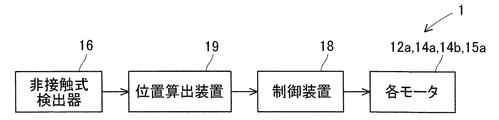
第一の研削盤は、クランクシャフトのクランクピン又はクランクジャーナルを研削する研削盤であって、前記クランクシャフトを回転可能に支持する主軸装置と、前記主軸装置に対して前記クランクシャフトの軸線方向であるZ軸方向及びその直交方向であるX軸方向に相対移動可能な砥石台と、前記砥石台に回転可能に設けられ、前記クランクピン又は前記クランクジャーナルを研削する砥石車と、前記砥石台に設けられ、前記クランクシャフトが前記主軸装置に支持された状態での前記クランクピン又は前記クランクジャーナルの位置状態を、前記クランクシャフトから前記X軸方向に離れた位置にて非接触で検出する非接触式検出器と、前記非接触式検出器による検出情報に基づいて前記クランクピン又は前記クランクジャーナルの端面位置を算出する位置算出装置と、前記砥石台を前記Z軸方向に相対移動することで前記非接触式検出器を前記クランクピン又は前記クランクジャーナルに対応する位置に移動し、前記位置にて前記非接触式検出器による検出を行い、その次に前記位置算出装置により算出された前記端面位置に基づいて前記砥石台を前記Z軸方向に相対的に位置決めして前記砥石車による前記クランクピン又は前記クランクジャーナルの研削を行う制御装置とを備える。
(1. First grinding machine)
The first grinding machine is a grinding machine for grinding a crankpin or a crank journal of a crankshaft, a spindle device that rotatably supports the crankshaft, and an axial direction of the crankshaft with respect to the spindle device A grinding wheel base that is relatively movable in a certain Z-axis direction and an X-axis direction that is orthogonal to the Z-axis direction, a grinding wheel that is rotatably provided on the grinding wheel base and grinds the crank pin or the crank journal, and the grinding wheel base. Non-contact detection that detects the position of the crank pin or the crank journal with the crank shaft supported by the spindle device at a position away from the crank shaft in the X-axis direction. An end of the crankpin or the crank journal based on detection information by the non-contact type detector and the non-contact type detector A position calculating device for calculating a position, and moving the non-contact detector to a position corresponding to the crank pin or the crank journal by relatively moving the grinding wheel head in the Z-axis direction; Detection is performed by a non-contact type detector, and then the grinding wheel base is relatively positioned in the Z-axis direction based on the end face position calculated by the position calculation device, and the crank pin or And a control device for grinding the crank journal.
(2.第二の研削盤)
第二の研削盤は、クランクシャフトのクランクピンを研削する研削盤であって、前記クランクシャフトを回転可能に支持する主軸装置と、前記主軸装置に対して前記クランクシャフトの軸線方向であるZ軸方向及びその直交方向であるX軸方向に相対移動可能な砥石台と、前記砥石台に回転可能に設けられ、前記クランクピンを研削する砥石車と、前記砥石台に設けられ、前記クランクシャフトが前記主軸装置に支持された状態での前記クランクピンの位置状態を、前記クランクシャフトから前記X軸方向に離れた位置にて非接触で検出する非接触式検出器と、前記非接触式検出器による検出情報に基づいて前記クランクピンの位相を算出する位置算出装置と、前記砥石台を前記Z軸方向に相対移動することで前記非接触式検出器を前記クランクピンに対応する位置に移動し、前記位置にて前記非接触式検出器による検出を行い、その次に前記位置算出装置により算出された前記位相に基づいて前記砥石台を前記Z軸方向に相対的に位置決めして前記砥石車による前記クランクピンの研削を行う制御装置とを備える。
(2. Second grinding machine)
The second grinding machine is a grinding machine for grinding a crankpin of a crankshaft, and a spindle device that rotatably supports the crankshaft, and a Z axis that is an axial direction of the crankshaft with respect to the spindle device A grinding wheel base that is relatively movable in the X-axis direction that is a direction perpendicular to the direction, a grinding wheel that is rotatably provided on the grinding wheel base, grinds the crank pin, and is provided on the grinding wheel base. A non-contact detector that detects the position of the crank pin in a state of being supported by the spindle device in a non-contact manner at a position away from the crank shaft in the X-axis direction; and the non-contact detector A position calculating device for calculating the phase of the crankpin based on detection information by the sensor, and moving the grindstone table in the Z-axis direction to move the non-contact detector to the clutch. It moves to a position corresponding to the cuppin, and is detected by the non-contact detector at the position, and then the grindstone base is moved relative to the Z-axis direction based on the phase calculated by the position calculation device. And a controller for grinding the crank pin by the grinding wheel.
(3.効果)
上記研削盤によれば、クランクシャフトが主軸装置に支持された状態において、非接触式検出器がクランクピン又はクランクジャーナルの位置状態を検出する。そのため、プリセットステーションなどが不要であるため、装置の大型化及び複雑化を招くことがない。
(3. Effect)
According to the grinding machine, the non-contact detector detects the position state of the crank pin or the crank journal in a state where the crank shaft is supported by the spindle device. Therefore, since a preset station or the like is unnecessary, the apparatus is not increased in size and complexity.
また、制御装置が、砥石台をZ軸方向に相対移動することにより、非接触式検出器をクランクピン又はクランクジャーナルに対応するZ軸方向位置に移動させる。この位置にて、非接触式検出器は、クランクピン又はクランクジャーナルの位置状態を検出する。このように、非接触式検出器は、クランクシャフトからX軸方向に離れた位置にて位置状態を検出する。従って、検出器をクランクピン又はクランクジャーナルの近傍にまで移動させる必要がなく、検出に要する時間が短縮できる。 Further, the control device moves the grindstone table in the Z-axis direction to move the non-contact detector to the Z-axis direction position corresponding to the crankpin or the crank journal. At this position, the non-contact detector detects the position state of the crank pin or the crank journal. Thus, the non-contact detector detects the position state at a position away from the crankshaft in the X-axis direction. Therefore, it is not necessary to move the detector to the vicinity of the crankpin or the crank journal, and the time required for detection can be shortened.
また、非接触式検出器及び砥石車が、砥石台に設けられる。従って、砥石台のX軸方向への移動に伴って、非接触式検出器がX軸方向に移動すると共に、砥石車がX軸方向に移動する。そのため、非接触式検出器による検出動作の後に、砥石台を研削位置までの移動量を少なくできるため、砥石車による研削が早く開始できる。 A non-contact detector and a grinding wheel are provided on the grinding wheel base. Therefore, as the grinding wheel platform moves in the X-axis direction, the non-contact detector moves in the X-axis direction and the grinding wheel moves in the X-axis direction. For this reason, after the detection operation by the non-contact type detector, the moving amount of the grinding wheel head to the grinding position can be reduced, so that grinding by the grinding wheel can be started quickly.
(1.研削盤の構成)
研削盤1の一例として、砥石台14をベッド11に対してトラバース(Z軸方向への移動)を行う砥石台トラバース型研削盤を例に挙げて説明する。ただし、本発明の研削盤1は、主軸装置12がベッド11に対してトラバース(Z軸方向への移動)を行うテーブルトラバース型研削盤にも適用できる。
(1. Configuration of grinding machine)
As an example of the
研削盤1による工作物は、クランクシャフトWである。クランクシャフトWは、クランクジャーナルWa、クランクピンWb及びクランクウェブWcを備える。研削盤1による研削部位は、クランクジャーナルWa及びクランクピンWbである。
The workpiece by the
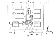
研削盤1について、図1及び図2を参照して説明する。研削盤1は、以下のように構成される。設置面にベッド11が固定され、ベッド11には、クランクシャフトWを回転可能に両端支持する主軸装置12及び心押装置13が取り付けられる。クランクシャフトWは、クランクジャーナルWaを中心に回転するように、主軸装置12及び心押装置13に支持される。つまり、クランクピンWbは、クランクシャフトWの回転中心から偏心した位置に位置する。主軸装置12は、クランクシャフトWを回転駆動するモータ12aを備える。
The
さらに、ベッド11上には、Z軸方向(クランクシャフトWの軸線方向)及びX軸方向(クランクシャフトWの軸線に直交する方向)に移動可能な砥石台14が設けられる。砥石台14は、モータ14aによってZ軸方向に移動し、モータ14bによってX軸方向に移動する。
Further, on the
砥石台14には、クランクピンWb又はクランクジャーナルWaを研削する砥石車15が回転可能に設けられる。砥石車15は、モータ15aによって回転駆動される。さらに、砥石台14には、クランクシャフトWが主軸装置12に支持された状態でのクランクピンWb又はクランクジャーナルWaの位置状態を、クランクシャフトWからX軸方向に離れた位置にて非接触で検出する非接触式検出器16が設けられる。
A grinding
非接触式検出器16の一例は、クランクピンWb又はクランクジャーナルWaをX軸方向から撮像するカメラであり、クランクピンWb又はクランクジャーナルWaの撮像情報を前述した位置状態として検出する。非接触式検出器16の他の例は、クランクピンWb又はクランクジャーナルWaまでのX軸方向の距離を計測するレーザ測定器であり、クランクピンWb又はクランクジャーナルWaまでの距離を前述した位置状態として検出する。
An example of the
さらに、ベッド11には、クランクシャフトWの研削部位であるクランクピンWb又はクランクジャーナルWaの外径を計測する定寸装置17が設けられる。さらに、研削盤1には、制御装置18が設けられる。制御装置18は、主軸装置12及び砥石車15を回転するモータ12a,15aを制御し、且つ、クランクシャフトWに対する砥石車15又は非接触式検出器16を相対移動するモータ14a,14bを制御する。
Further, the
研削盤1の上記の他の構成について、図2を参照して説明する。図2に示すように、研削盤1は、上記の他に、位置算出装置19を備える。位置算出装置19は、非接触式検出器16による検出情報に基づいてクランクピンWb又はクランクジャーナルWaの端面位置及び位相を算出する。位置算出装置19により端面位置及び位相を算出する際の算出方法については後述する。
The other configuration of the grinding
(2.制御装置による第一例の処理)
次に、複数のクランクピンWbを研削する場合について、制御装置18による処理のうち、クランクピンWbの端面位置及び位相を検出し、研削を開始するまでの処理について、図3−図5を参照して説明する。なお、クランクジャーナルWaを研削する場合には、以下において、クランクピンWbの位相の検出を行う箇所を除き、実質的に共通する。
(2. Processing of the first example by the control device)
Next, in the case of grinding a plurality of crank pins Wb, of the processing by the
まず、ロボット(図示せず)が、クランクシャフトWを主軸装置12による支持位置に搬送する。このとき、ロボットは、クランクシャフトWの回転姿勢を所定位相範囲内となるように把持している。そして、制御装置18は、主軸装置12及び心押装置13による支持処理を行う(S1)。つまり、主軸装置12及び心押装置13により、クランクシャフトWを把持する。この状態において、クランクシャフトWの回転姿勢は、所定位相範囲内となるが、研削ができる程度の高精度な位置決めではない。
First, a robot (not shown) conveys the crankshaft W to a support position by the
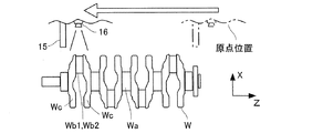
続いて、制御装置18は、図4に示すように、砥石台14を原点位置からZ軸方向(図4の左側)に移動して、非接触式検出器16を主軸装置12に最も近いクランクピンWbに対応する検出位置に位置決めする(S2)。検出位置は、図4に示すように、該当するクランクピンWbに対して、X軸方向に離れた位置であって、クランクピンWbにX軸方向に対向する位置である。ここで、検出位置は、検出位置から砥石台14をZ軸方向に移動させた場合に、砥石台14に取り付けられる部材、すなわち、砥石車15及び非接触式検出器16がクランクシャフトWに干渉しない位置となる。つまり、検出位置は、クランクピンWbからX軸方向に離れているだけでなく、クランクウェブWcからもX軸方向に離れた位置となる。
Subsequently, as shown in FIG. 4, the
続いて、制御装置18は、非接触式検出器16による検出処理を行う(S3)。検出処理は、クランクシャフトWが主軸装置12に支持された状態でのクランクピンWbの位置状態を検出する処理である。非接触式検出器16は、カメラの場合にはクランクピンWb及びその周囲を撮像し、レーザ測定器の場合にはクランクピンWbの外周面及び端面、並びに、クランクウェブWcの端面までの距離を測定する。
Subsequently, the
続いて、制御装置18は、主軸装置12のモータ12aを制御して、クランクシャフトWを所定角度旋回する(S4)。本実施形態においては、旋回角度は、90°とする。再び、制御装置18は、非接触式検出器16による検出処理を行う(S5)。このように、非接触式検出器16は、1つのクランクピンWbの2か所の位相について検出処理を行う。
Subsequently, the
ここで、位置算出装置19が、非接触式検出器16により検出されたクランクピンWbの2か所の位置状態に関する検出情報に基づいて、クランクピンWbの端面位置及び位相を算出する(S10)。この処理については、後述する。
Here, the
続いて、制御装置18は、図5に示すように、位置算出装置19により算出されたクランクピンWbの端面位置に基づいて、砥石台14をZ軸方向に移動して、砥石車15をクランクピンWbの研削位置に位置決めする(S6)。このとき、砥石台14は、原点位置に戻ることなく、検出位置から研削位置に移動する。
Subsequently, as shown in FIG. 5, the
研削位置とは、砥石車15がクランクピンWbの軸線方向の中央に位置する状態である。つまり、研削時において、砥石車15の両端面とクランクウェブWcの端面との距離が、ほぼ等しい状態となる。続いて、制御装置18は、図5に示すように、砥石台14をX軸方向に移動して、研削を行う(S7)。
The grinding position is a state in which the
(3.非接触式検出器がカメラのときの位置算出装置による位相の算出処理)
次に、非接触式検出器16がカメラである場合において、位置算出装置19によるクランクピンWbの位相の算出処理について、図3のフローチャートの他に、図6及び図7を参照して説明する。図3のS3におけるクランクシャフトWを旋回する前のクランクピンWb1の位置状態(検出情報、撮像情報)の検出処理(撮像処理)は、図6に示す。また、図3のS5におけるクランクシャフトWの旋回後のクランクピンWb2の位置状態(検出情報、撮像情報)の検出処理(撮像処理)は、図7に示す。
(3. Phase calculation processing by the position calculation device when the non-contact detector is a camera)
Next, in the case where the
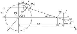
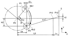
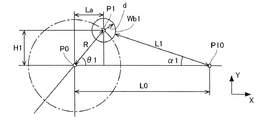
ここで、図6及び図7において、クランクシャフトWの回転中心をP0とし、クランクピンWbの中心の旋回半径をRとし、カメラである非接触式検出器16の焦点をP10とし、撮像センサ(イメージセンサ)の検出面をSとし、回転中心P0から焦点P10までの距離をL0とし、焦点P10から撮像センサの検出面Sまでの距離をLsとする。
6 and 7, the rotation center of the crankshaft W is P0, the turning radius of the center of the crankpin Wb is R, the focal point of the
図6に示す状態における旋回前のクランクピンWb1の中心位置をP1とし、撮像センサにおいて位置P1に対応する位置をP11とし、撮像センサの検出面Sにおいてセンサ中心と位置P11とのY軸方向距離をh1とし、クランクピンWb1の中心位置P1と回転中心P0とのX軸方向距離をLaとし、Y軸方向距離をH1とする。クランクピンWb1の位相をθ1とし、焦点P10におけるクランクピンWb1への角度をα1とする。 The center position of the crankpin Wb1 before turning in the state shown in FIG. 6 is P1, the position corresponding to the position P1 in the image sensor is P11, and the Y-axis direction distance between the sensor center and the position P11 on the detection surface S of the image sensor , H1, the X-axis direction distance between the center position P1 of the crank pin Wb1 and the rotation center P0 is La, and the Y-axis direction distance is H1. The phase of the crankpin Wb1 is θ1, and the angle to the crankpin Wb1 at the focal point P10 is α1.
図7に示す状態における旋回後のクランクピンWb2の中心位置をP2とし、撮像センサにおいて位置P2に対応する位置をP12とし、撮像センサの検出面Sにおいてセンサ中心と位置P12とのY軸方向距離をh2とし、クランクピンWb2の中心位置P2と回転中心P0とのX軸方向距離をLbとし、Y軸方向距離をH2とする。クランクピンWb2の位相をθ2とし、焦点P10におけるクランクピンWb2への角度をα2とする。 The center position of the crankpin Wb2 after turning in the state shown in FIG. 7 is P2, the position corresponding to the position P2 in the imaging sensor is P12, and the Y-axis direction distance between the sensor center and the position P12 on the detection surface S of the imaging sensor , H2, the distance in the X-axis direction between the center position P2 of the crank pin Wb2 and the rotation center P0 is Lb, and the distance in the Y-axis direction is H2. The phase of the crank pin Wb2 is θ2, and the angle to the crank pin Wb2 at the focal point P10 is α2.
この場合、以下の式(1)−(9)が成り立つ。L0、Ls、Rは、既知である。h1、h2は、検出可能な値である。従って、式(1)−(9)を解くことにより、位相θ1が算出される。 In this case, the following expressions (1) to (9) are established. L0, Ls, and R are known. h1 and h2 are detectable values. Therefore, the phase θ1 is calculated by solving the equations (1)-(9).

ここで、上記の算出方法において、位置算出装置19は、クランクピンWb1,Wb2の外周面位置に基づいて、位置P11,P12を算出する。ここで、位置算出装置19は、クランクピンWb1,Wb2の外周面のある1点に基づいて、位置P11,P12を算出することができる。
Here, in the above calculation method, the
ただし、位置算出装置19は、クランクピンWb1,Wb2の外周面における複数の軸線方向位置に基づいて、例えば、平均処理や近似処理を行うことにより、位置P11,P12を算出してもよい。具体的には、位置算出装置19は、クランクピンWbの外周面における複数の軸線方向位置を算出し、複数の軸線方向位置に基づいてクランクピンWbの位相を算出する。この場合、例えば、クランクピンWb1,Wb2の表面に異物が付着している場合などに、その影響を受けにくくすることができ、高精度に位相の算出ができる。
However, the
(4.クランクシャフトWの初期位置決め位相)
ここで、制御装置18による処理の図3のS1の前において、ロボット(図示せず)が、クランクシャフトWを主軸装置12による支持位置に搬送するとき、ロボットは、クランクシャフトWの回転姿勢を所定位相範囲内となるように把持している。
(4. Initial positioning phase of crankshaft W)
Here, before S1 of FIG. 3 of the processing by the
図4に示すように、初期状態において、クランクピンWb1の位相θ1が45°付近となるように、クランクシャフトWは主軸装置12に支持される。そして、制御装置18は、図3のS4において、クランクシャフトWを90°旋回させる。つまり、図5に示すように、クランクピンWb2の位相θ2が45°付近となるように、クランクシャフトWは主軸装置12に支持される。
As shown in FIG. 4, in the initial state, the crankshaft W is supported by the
つまり、旋回前後の位相θ1、θ2が、所定位相範囲内となるように、初期状態のクランクシャフトWの位相が決定される。換言すると、図5に示すように、旋回前のクランクピンWb1の中心位置P1と旋回後のクランクピンWb2の中心位置P2とのX軸方向距離ΔLが、所定値以内となるようにされる。 That is, the phase of the crankshaft W in the initial state is determined so that the phases θ1 and θ2 before and after turning are within the predetermined phase range. In other words, as shown in FIG. 5, the X-axis direction distance ΔL between the center position P1 of the crankpin Wb1 before turning and the center position P2 of the crankpin Wb2 after turning is set within a predetermined value.
上記により、検出する2か所の位相において、非接触式検出器16の撮像センサ面Sからの距離が同程度となるため、非接触式検出器16による検出誤差が小さくなる。その結果、クランクピンWb1の位相θ1が高精度に算出される。
As described above, since the distance from the imaging sensor surface S of the
(5.非接触式検出器がレーザ測定器のときの位置算出装置による位相の算出処理)
次に、非接触式検出器16がレーザ測定器である場合において、位置算出装置19によるクランクピンWbの位相の算出処理について、図3のフローチャートの他に、図8及び図9を参照して説明する。図3のS3におけるクランクシャフトWを旋回する前のクランクピンWb1の位置状態(検出情報、撮像情報)の検出処理(撮像処理)は、図8に示す。また、図3のS5におけるクランクシャフトWの旋回後のクランクピンWb2の位置状態(検出情報、撮像情報)の検出処理(撮像処理)は、図9に示す。
(5. Phase calculation processing by the position calculation device when the non-contact detector is a laser measuring device)
Next, in the case where the
ここで、図8において、レーザ測定器の位置をP10とし、レーザ測定器によるクランクピンWb1の外周面までの離間距離をL1とし、クランクピンWb1の半径をdとする。また、図9において、レーザ測定器によるクランクピンWb2の外周面までの離間距離をL2とする。その他の符号は、図6,7と同様である。 Here, in FIG. 8, the position of the laser measuring device is P10, the distance from the outer peripheral surface of the crankpin Wb1 by the laser measuring device is L1, and the radius of the crankpin Wb1 is d. In FIG. 9, the distance from the outer peripheral surface of the crankpin Wb2 by the laser measuring instrument is L2. Other symbols are the same as those in FIGS.
この場合、以下の式(11)−(19)が成り立つ。L0、R、dは、既知である。L1、L2は、検出可能な値である。従って、式(11)−(19)を解くことにより、位相θ1が算出される。 In this case, the following expressions (11) to (19) are established. L0, R, and d are known. L1 and L2 are detectable values. Therefore, the phase θ1 is calculated by solving the equations (11)-(19).
(6.位置算出装置による端面位置の算出処理)
次に、位置算出装置19は、図3のS3におけるクランクシャフトWを旋回する前のクランクピンWb1の端面位置(クランクウェブWcの端面位置)を算出する。非接触式検出器16は、カメラである場合においては、クランクピンWb1の撮像情報を、クランクピンWb1の位置状態として検出する。
(6. End face position calculation processing by position calculation device)
Next, the
そして、位置算出装置19は、撮像情報に基づいて、クランクピンWb1の端面位置(クランクウェブWcの端面位置)を算出する。ここで、位置算出装置19は、クランクピンWb1の端面位置に相当するある1点に基づいて、クランクピンWb1の端面位置を算出することができる。
Then, the
ただし、位置算出装置19は、クランクピンWb1の端面位置に相当する複数位置に基づいて、例えば、平均処理や近似処理を行うことにより、端面位置を算出してもよい。具体的には、位置算出装置19は、クランクウェブWcの端面における複数の径方向位置を算出し、複数の径方向位置に基づいてクランクピンWbの端面位置を算出する。この場合、例えば、クランクウェブWcの表面に異物が付着している場合などに、その影響を受けにくくすることができ、高精度に端面位置の算出ができる。
However, the
(7.制御装置による第二例の処理)
次に、制御装置18による第二例の処理について、図10−図11を参照して説明する。まず、ロボット(図示せず)が、クランクシャフトWを主軸装置12による支持位置に搬送する。そして、制御装置18は、主軸装置12及び心押装置13による支持処理を行う(S21)。
(7. Processing of second example by control device)
Next, the process of the 2nd example by the
続いて、制御装置18は、図11に示すように、砥石台14を原点位置からZ軸方向(図11の左側)に移動して、非接触式検出器16を主軸装置12から2番目のクランクピンWb3に対応する検出位置に位置決めする(S22)。検出位置は、図11に示すように、該当するクランクピンWb3に対して、X軸方向に離れた位置であって、クランクピンWbにX軸方向に対向する位置である。
Subsequently, as shown in FIG. 11, the
続いて、制御装置18は、非接触式検出器16による検出処理を行う(S23)。検出処理は、クランクシャフトWが主軸装置12に支持された状態でのクランクピンWbの位置状態を検出する処理である。
Subsequently, the
続いて、制御装置18は、図11に示すように、砥石台14をさらにZ軸方向(図11の左側)に移動して、非接触式検出器16を主軸装置12に最も近いクランクピンWb1に対応する検出位置に位置決めする(S24)。再び、制御装置18は、非接触式検出器16による検出処理を行う(S25)。ここで、クランクピンWb1,Wb3は、異なる位相に位置する。つまり、非接触式検出器16は、異なる位相に位置する2つのクランクピンWb1,Wb3の位置状態について検出処理を行う。
Subsequently, as shown in FIG. 11, the
ここで、位置算出装置19が、非接触式検出器16により検出された2つのクランクピンWb1,Wb3の位置状態に関する検出情報の何れか一方に基づいて、クランクピンWbの端面位置を算出する(S30)。さらに、位置算出装置19が、非接触式検出器16により検出された2つのクランクピンWb1,Wb3の位置状態に関する検出情報に基づいて、クランクピンWbの位相を算出する(S30)。この処理については、後述する。
Here, the
続いて、制御装置18は、位置算出装置19により算出されたクランクピンWb1,Wb3の端面位置に基づいて、砥石台14をZ軸方向に移動して、砥石車15を原点位置に戻すことなくクランクピンWbの研削位置に位置決めする(S26)。続いて、制御装置18は、砥石台14をX軸方向に移動して、研削を行う(S27)。
Subsequently, the
(8.非接触式検出器がカメラのときの位置算出装置による位相の算出処理)
次に、第二例の制御処理のときに、非接触式検出器16がカメラである場合において、位置算出装置19によるクランクピンWbの位相の算出処理について、図10のフローチャートの他に、図6及び図12を参照して説明する。図10のS23におけるクランクピンWb3の位置状態(検出情報、撮像情報)の検出処理(撮像処理)は、図12に示す。また、図10のS25におけるクランクピンWb1の位置状態(検出情報、撮像情報)の検出処理(撮像処理)は、図6に示す。なお、図6については、上述したとおりである。
(8. Phase calculation process by position calculation device when non-contact detector is a camera)
Next, in the control process of the second example, when the
図12に示す状態におけるクランクピンWb3の中心位置をP3とし、撮像センサにおいて位置P3に対応する位置をP13とし、撮像センサの検出面Sにおいてセンサ中心と位置P13とのY軸方向距離をh3とし、クランクピンWb3の中心位置P3と回転中心P0とのX軸方向距離をLcとし、Y軸方向距離をH3とする。クランクピンWb3の位相をθ1であり、焦点P10におけるクランクピンWb3への角度をα3とする。 The center position of the crankpin Wb3 in the state shown in FIG. 12 is P3, the position corresponding to the position P3 in the imaging sensor is P13, and the Y-axis direction distance between the sensor center and the position P13 on the detection surface S of the imaging sensor is h3. The distance in the X-axis direction between the center position P3 of the crank pin Wb3 and the rotation center P0 is Lc, and the distance in the Y-axis direction is H3. The phase of the crankpin Wb3 is θ1, and the angle to the crankpin Wb3 at the focal point P10 is α3.
この場合、以下の式(21)−(27)が成り立つ。L0、Ls、Rは、既知である。h1、h3は、検出可能な値である。従って、式(21)−(27)を解くことにより、位相θ1が算出される。 In this case, the following expressions (21) to (27) are established. L0, Ls, and R are known. h1 and h3 are detectable values. Therefore, the phase θ1 is calculated by solving the equations (21)-(27).
(9.非接触式検出器がレーザ測定器のときの位置算出装置による位相の算出処理)
次に、第二例の制御処理のときに、非接触式検出器16がレーザ測定器である場合において、位置算出装置19によるクランクピンWbの位相の算出処理について、図10のフローチャートの他に、図8及び図13を参照して説明する。図10のS23におけるクランクピンWb3の位置状態(検出情報、撮像情報)の検出処理(撮像処理)は、図13に示す。また、図10のS25におけるクランクピンWb1の位置状態(検出情報、撮像情報)の検出処理(撮像処理)は、図8に示す。なお、図8については、上述したとおりである。
(9. Phase calculation processing by the position calculation device when the non-contact detector is a laser measuring device)
Next, in the case of the control process of the second example, when the
ここで、図13において、レーザ測定器によるクランクピンWb3の外周面までの離間距離をL3とし、クランクピンWb3の半径をdとする。その他の符号は、図6,7と同様である。 Here, in FIG. 13, the distance to the outer peripheral surface of the crankpin Wb3 by the laser measuring instrument is L3, and the radius of the crankpin Wb3 is d. Other symbols are the same as those in FIGS.
この場合、以下の式(31)−(37)が成り立つ。L0、R、dは、既知である。L1、L3は、検出可能な値である。従って、式(31)−(37)を解くことにより、位相θ1が算出される。 In this case, the following expressions (31) to (37) are established. L0, R, and d are known. L1 and L3 are detectable values. Therefore, the phase θ1 is calculated by solving the equations (31)-(37).
(10.実施形態の効果)
上述した研削盤1は、クランクシャフトWのクランクピンWb又はクランクジャーナルWaを研削する。研削盤1は、クランクシャフトWを回転可能に支持する主軸装置12と、主軸装置12に対してクランクシャフトWの軸線方向であるZ軸方向及びその直交方向であるX軸方向に相対移動可能な砥石台14と、砥石台14に回転可能に設けられ、クランクピンWb又はクランクジャーナルWaを研削する砥石車15と、砥石台14に設けられ、クランクシャフトWが主軸装置12に支持された状態でのクランクピンWb又はクランクジャーナルWaの位置状態を、クランクシャフトWからX軸方向に離れた位置にて非接触で検出する非接触式検出器16と、非接触式検出器16による検出情報に基づいてクランクピンWb又はクランクジャーナルWaの端面位置を算出する位置算出装置19と、制御装置18とを備える。
(10. Effects of the embodiment)
The grinding
制御装置18は、砥石台14をZ軸方向に相対移動することで非接触式検出器16をクランクピンWb又はクランクジャーナルWaに対応する位置に移動し、当該位置にて非接触式検出器16による検出を行い、その次に位置算出装置19により算出された端面位置に基づいて砥石台14をZ軸方向に相対的に位置決めして砥石車15によるクランクピンWb又はクランクジャーナルWaの研削を行う。
The
また、位置算出装置19は、非接触式検出器16による検出情報に基づいてクランクピンWbの位相を算出し、制御装置18は、位置算出装置19により算出された端面位置及び位相に基づいて砥石台14をZ軸方向に相対的に位置決めして砥石車15によるクランクピンWbの研削を行う。
Further, the
なお、位置算出装置19は、クランクピンWb又はクランクジャーナルWaの端面位置のみの算出を行ってもよいし、クランクピンWbの位相のみの算出を行うようにしてもよい。
Note that the
上記研削盤1によれば、クランクシャフトWが主軸装置12に支持された状態において、非接触式検出器16がクランクピンWb又はクランクジャーナルWaの位置状態を検出する。そのため、プリセットステーションなどが不要であるため、装置の大型化及び複雑化を招くことがない。
According to the grinding
また、制御装置18が、砥石台14をZ軸方向に相対移動することにより、非接触式検出器16をクランクピンWb又はクランクジャーナルWaに対応するZ軸方向位置に移動させる。この位置にて、非接触式検出器16は、クランクピンWb又はクランクジャーナルWaの位置状態を検出する。このように、非接触式検出器16は、クランクシャフトWからX軸方向に離れた位置にて位置状態を検出する。従って、非接触式検出器16をクランクピンWb又はクランクジャーナルWaの近傍にまで移動させる必要がなく、検出に要する時間が短縮できる。
Further, the
また、非接触式検出器16及び砥石車15が、砥石台14に設けられる。従って、砥石台14のX軸方向への移動に伴って、非接触式検出器16がX軸方向に移動すると共に、砥石車15がX軸方向に移動する。そのため、非接触式検出器16による検出動作の後に、砥石台14を研削位置までの移動量を少なくできるため、砥石車15による研削が早く開始できる。
A
また、非接触式検出器16は、第一例としては、クランクピンWb又はクランクジャーナルWaをX軸方向から撮像するカメラであり、クランクピンWb又はクランクジャーナルWaの撮像情報を位置状態として検出する。この場合、位置算出装置19は、カメラによる撮像情報に基づいて、容易に且つ確実にクランクピンWbの端面位置及び位相、又は、クランクジャーナルWaの端面位置を算出できる。
Further, as a first example, the
また、非接触式検出器16は、第二例としては、クランクピンWb又はクランクジャーナルWaまでのX軸方向の距離を計測するレーザ測定器であり、クランクピンWb又はクランクジャーナルWaまでの距離を位置状態として検出する。この場合も、位置算出装置19は、レーザ測定器により測定された距離に基づいて、容易に且つ確実にクランクピンWbの端面位置及び位相、又は、クランクジャーナルWaの端面位置を算出できる。
Further, as a second example, the
また、制御装置18の第一例の処理として説明したように、非接触式検出器16は、クランクシャフトWを旋回させて位置決めされた少なくとも2か所の位相におけるクランクピンWbの位置状態をそれぞれ検出し、位置算出装置19は、クランクピンWbの複数の位相における検出情報に基づいて、クランクピンWbの位相を算出するようにしてもよい。この場合、確実にクランクピンWbの位相の算出ができる。
Further, as described as the processing of the first example of the
また、非接触式検出器16により検出する際のクランクピンWbの2か所の位相は、非接触式検出器16からそれぞれのクランクピンWbまでの距離が所定範囲内に含まれる位相に設定される。例えば、位相θ1、θ2を、同程度の角度となるようにしている。これにより、誤差を小さくできるため、高精度に位相の算出が可能となる。
In addition, the two phases of the crank pin Wb at the time of detection by the
また、制御装置18の第二例の処理として説明したように、クランクシャフトWは、異なる位相に位置する複数のクランクピンWbを備える場合には、非接触式検出器16は、クランクシャフトWを旋回させない状態で複数のクランクピンWbの位置状態をそれぞれ検出し、位置算出装置19は、検出された複数のクランクピンWbの検出情報に基づいて、複数のクランクピンWbの位相を算出することもできる。この場合も、確実にクランクピンWbの位相の算出ができる。
Further, as described in the processing of the second example of the
また、位置算出装置19は、非接触式検出器16により検出された検出情報に基づいて、クランクシャフトWのクランクウェブWcの端面における複数の径方向位置を算出し、複数の径方向位置に基づいてクランクピンWb又はクランクジャーナルWaの端面位置を算出するようにしてもよい。この場合、クランクウェブWcの端面に異物が付着している場合であっても、その影響を受けにくくすることができ、高精度にクランクピンWb又はクランクジャーナルWaの端面位置の算出ができる。
Further, the
また、位置算出装置19は、非接触式検出器16により検出された検出情報に基づいて、クランクピンWbの外周面における複数の軸線方向位置を算出し、複数の軸線方向位置に基づいてクランクピンWbの位相を算出するようにしてもよい。この場合、クランクピンWbの外周面に異物が付着している場合であっても、その影響を受けにくくすることができ、高精度にクランクピンWbの位相の算出ができる。
Further, the
また、制御装置18は、砥石台14を非接触式検出器16による検出位置に移動した後に、砥石台14を原点位置に戻すことなく、砥石台14を研削位置に移動する。これにより、端面位置及び位相の算出後に、早期に研削を開始できる。
Further, the
1:研削盤、 11:ベッド、 12:主軸装置、 13:心押装置、 14:砥石台、 15:砥石車、 16:非接触式検出器、 17:定寸装置、 18:制御装置、 19:位置算出装置、 W:クランクシャフト、 Wa:クランクジャーナル、 Wb:クランクピン、 Wc:クランクウェブ 1: Grinding machine, 11: Bed, 12: Spindle device, 13: Tailstock device, 14: Grinding wheel base, 15: Grinding wheel, 16: Non-contact type detector, 17: Sizing device, 18: Control device, 19 : Position calculation device, W: Crankshaft, Wa: Crank journal, Wb: Crank pin, Wc: Crank web
Claims (11)
前記クランクシャフトを回転可能に支持する主軸装置と、
前記主軸装置に対して前記クランクシャフトの軸線方向であるZ軸方向及びその直交方向であるX軸方向に相対移動可能な砥石台と、
前記砥石台に回転可能に設けられ、前記クランクピン又は前記クランクジャーナルを研削する砥石車と、
前記砥石台に設けられ、前記クランクシャフトが前記主軸装置に支持された状態での前記クランクピン又は前記クランクジャーナルの位置状態を、前記クランクシャフトから前記X軸方向に離れた位置にて非接触で検出する非接触式検出器と、
前記非接触式検出器による検出情報に基づいて前記クランクピン又は前記クランクジャーナルの端面位置を算出する位置算出装置と、
前記砥石台を前記Z軸方向に相対移動することで前記非接触式検出器を前記クランクピン又は前記クランクジャーナルに対応する位置に移動し、前記位置にて前記非接触式検出器による検出を行い、その次に前記位置算出装置により算出された前記端面位置に基づいて前記砥石台を前記Z軸方向に相対的に位置決めして前記砥石車による前記クランクピン又は前記クランクジャーナルの研削を行う制御装置と、
を備える、研削盤。 A grinder for grinding a crankpin or crank journal of a crankshaft,
A spindle device for rotatably supporting the crankshaft;
A whetstone base that is movable relative to the main shaft device in the Z-axis direction that is the axial direction of the crankshaft and the X-axis direction that is orthogonal to the Z-axis direction;
A grinding wheel that is rotatably provided on the grinding wheel table and grinds the crank pin or the crank journal; and
The position of the crank pin or the crank journal provided in the grindstone table and supported by the spindle device is contactless at a position away from the crank shaft in the X-axis direction. A non-contact detector to detect,
A position calculation device that calculates the position of the end face of the crank pin or the crank journal based on detection information by the non-contact detector;
The non-contact detector is moved to a position corresponding to the crank pin or the crank journal by moving the grindstone table in the Z-axis direction, and the non-contact detector detects at the position. Then, a control device for grinding the crank pin or the crank journal by the grinding wheel by positioning the grinding wheel base relatively in the Z-axis direction based on the end face position calculated by the position calculating device. When,
A grinding machine.
前記制御装置は、前記位置算出装置により算出された前記端面位置及び前記位相に基づいて前記砥石台を前記Z軸方向に相対的に位置決めして前記砥石車による前記クランクピンの研削を行う、請求項1−3の何れか一項に記載の研削盤。 The position calculating device calculates the phase of the crankpin based on detection information by the non-contact detector,
The said control apparatus positions the said grindstone base relatively in the said Z-axis direction based on the said end surface position and the said phase which were calculated by the said position calculation apparatus, and grinds the said crankpin with the said grinding wheel. The grinder as described in any one of claim | item 1-3.
前記位置算出装置は、前記クランクピンの複数の位相における検出情報に基づいて、前記クランクピンの位相を算出する、請求項4に記載の研削盤。 The non-contact detector detects a position state of the crank pin in at least two phases positioned by turning the crank shaft;
The grinding machine according to claim 4, wherein the position calculation device calculates the phase of the crankpin based on detection information in a plurality of phases of the crankpin.
前記非接触式検出器は、前記クランクシャフトを旋回させない状態で複数の前記クランクピンの位置状態をそれぞれ検出し、
前記位置算出装置は、検出された複数の前記クランクピンの検出情報に基づいて、複数の前記クランクピンの位相を算出する、請求項4に記載の研削盤。 The crankshaft includes a plurality of the crankpins positioned at different phases,
The non-contact detector detects a position state of each of the plurality of crank pins without rotating the crank shaft;
The grinding machine according to claim 4, wherein the position calculation device calculates phases of the plurality of crank pins based on the detected detection information of the plurality of crank pins.
前記クランクシャフトを回転可能に支持する主軸装置と、
前記主軸装置に対して前記クランクシャフトの軸線方向であるZ軸方向及びその直交方向であるX軸方向に相対移動可能な砥石台と、
前記砥石台に回転可能に設けられ、前記クランクピンを研削する砥石車と、
前記砥石台に設けられ、前記クランクシャフトが前記主軸装置に支持された状態での前記クランクピンの位置状態を、前記クランクシャフトから前記X軸方向に離れた位置にて非接触で検出する非接触式検出器と、
前記非接触式検出器による検出情報に基づいて前記クランクピンの位相を算出する位置算出装置と、
前記砥石台を前記Z軸方向に相対移動することで前記非接触式検出器を前記クランクピンに対応する位置に移動し、前記位置にて前記非接触式検出器による検出を行い、その次に前記位置算出装置により算出された前記位相に基づいて前記砥石台を前記Z軸方向に相対的に位置決めして前記砥石車による前記クランクピンの研削を行う制御装置と、
を備える、研削盤。 A grinding machine for grinding a crankpin of a crankshaft,
A spindle device for rotatably supporting the crankshaft;
A whetstone base that is movable relative to the main shaft device in the Z-axis direction that is the axial direction of the crankshaft and the X-axis direction that is orthogonal to the Z-axis direction;
A grinding wheel that is rotatably provided on the grinding wheel platform and grinds the crank pin;
Non-contact that is provided on the grindstone table and detects the position of the crank pin in a state where the crank shaft is supported by the main spindle device at a position away from the crank shaft in the X-axis direction. An equation detector;
A position calculating device that calculates the phase of the crankpin based on detection information by the non-contact detector;
The non-contact detector is moved to a position corresponding to the crankpin by moving the grindstone table in the Z-axis direction, and the non-contact detector detects at the position, and then A control device for grinding the crank pin by the grinding wheel by relatively positioning the grinding wheel base in the Z-axis direction based on the phase calculated by the position calculating device;
A grinding machine.
Priority Applications (3)
| Application Number | Priority Date | Filing Date | Title |
|---|---|---|---|
| JP2015125485A JP6620436B2 (en) | 2015-06-23 | 2015-06-23 | Grinder |
| DE102016111329.8A DE102016111329A1 (en) | 2015-06-23 | 2016-06-21 | grinding machine |
| CN201610453162.XA CN106272070B (en) | 2015-06-23 | 2016-06-21 | Grinding machine |
Applications Claiming Priority (1)
| Application Number | Priority Date | Filing Date | Title |
|---|---|---|---|
| JP2015125485A JP6620436B2 (en) | 2015-06-23 | 2015-06-23 | Grinder |
Publications (2)
| Publication Number | Publication Date |
|---|---|
| JP2017007038A true JP2017007038A (en) | 2017-01-12 |
| JP6620436B2 JP6620436B2 (en) | 2019-12-18 |
Family
ID=57537521
Family Applications (1)
| Application Number | Title | Priority Date | Filing Date |
|---|---|---|---|
| JP2015125485A Active JP6620436B2 (en) | 2015-06-23 | 2015-06-23 | Grinder |
Country Status (3)
| Country | Link |
|---|---|
| JP (1) | JP6620436B2 (en) |
| CN (1) | CN106272070B (en) |
| DE (1) | DE102016111329A1 (en) |
Cited By (2)
| Publication number | Priority date | Publication date | Assignee | Title |
|---|---|---|---|---|
| JP2019063962A (en) * | 2017-10-04 | 2019-04-25 | 株式会社ジェイテクト | Machine tool |
| JP2020203365A (en) * | 2019-06-19 | 2020-12-24 | マツダ株式会社 | Processing method for crank shaft |
Citations (7)
| Publication number | Priority date | Publication date | Assignee | Title |
|---|---|---|---|---|
| JPH1190800A (en) * | 1997-09-17 | 1999-04-06 | Toyoda Mach Works Ltd | Grinding method and grinding device for crank pin and rigidity measuring device for crankshaft |
| JP2005138201A (en) * | 2003-11-05 | 2005-06-02 | Nissan Motor Co Ltd | Crankshaft processing device and processing method |
| JP2006150525A (en) * | 2004-11-30 | 2006-06-15 | Toyota Motor Corp | Phase determination device, phase determination tool, and phase determination method |
| JP2010105078A (en) * | 2008-10-28 | 2010-05-13 | Jtekt Corp | Grinder system and grinding method |
| KR101202117B1 (en) * | 2012-08-27 | 2012-11-15 | 유로비젼 (주) | Heat treatment apparatus for crank shaft |
| US20140183174A1 (en) * | 2012-12-28 | 2014-07-03 | Hyundai Motor Company | Heat treatment device for crank shaft |
| CN105403148A (en) * | 2015-11-27 | 2016-03-16 | 天津大学 | Measurement apparatus of center position accuracy of all journals of crank shaft, and measurement and calibration methods thereof |
Family Cites Families (2)
| Publication number | Priority date | Publication date | Assignee | Title |
|---|---|---|---|---|
| DE102006024715B4 (en) * | 2006-05-26 | 2008-07-24 | Niles-Simmons Industrieanlagen Gmbh | Method for processing the bearing seats of the main and stroke bearings of crankshafts and machine tool for carrying out the method |
| BRPI1003635A2 (en) * | 2009-07-28 | 2019-06-11 | Komatsu Ntc Ltd | grinding machine and measuring device |
-
2015
- 2015-06-23 JP JP2015125485A patent/JP6620436B2/en active Active
-
2016
- 2016-06-21 DE DE102016111329.8A patent/DE102016111329A1/en active Pending
- 2016-06-21 CN CN201610453162.XA patent/CN106272070B/en active Active
Patent Citations (7)
| Publication number | Priority date | Publication date | Assignee | Title |
|---|---|---|---|---|
| JPH1190800A (en) * | 1997-09-17 | 1999-04-06 | Toyoda Mach Works Ltd | Grinding method and grinding device for crank pin and rigidity measuring device for crankshaft |
| JP2005138201A (en) * | 2003-11-05 | 2005-06-02 | Nissan Motor Co Ltd | Crankshaft processing device and processing method |
| JP2006150525A (en) * | 2004-11-30 | 2006-06-15 | Toyota Motor Corp | Phase determination device, phase determination tool, and phase determination method |
| JP2010105078A (en) * | 2008-10-28 | 2010-05-13 | Jtekt Corp | Grinder system and grinding method |
| KR101202117B1 (en) * | 2012-08-27 | 2012-11-15 | 유로비젼 (주) | Heat treatment apparatus for crank shaft |
| US20140183174A1 (en) * | 2012-12-28 | 2014-07-03 | Hyundai Motor Company | Heat treatment device for crank shaft |
| CN105403148A (en) * | 2015-11-27 | 2016-03-16 | 天津大学 | Measurement apparatus of center position accuracy of all journals of crank shaft, and measurement and calibration methods thereof |
Cited By (4)
| Publication number | Priority date | Publication date | Assignee | Title |
|---|---|---|---|---|
| JP2019063962A (en) * | 2017-10-04 | 2019-04-25 | 株式会社ジェイテクト | Machine tool |
| JP7000785B2 (en) | 2017-10-04 | 2022-01-19 | 株式会社ジェイテクト | Machine Tools |
| JP2020203365A (en) * | 2019-06-19 | 2020-12-24 | マツダ株式会社 | Processing method for crank shaft |
| JP7312371B2 (en) | 2019-06-19 | 2023-07-21 | マツダ株式会社 | Crankshaft processing method |
Also Published As
| Publication number | Publication date |
|---|---|
| DE102016111329A1 (en) | 2016-12-29 |
| CN106272070A (en) | 2017-01-04 |
| JP6620436B2 (en) | 2019-12-18 |
| CN106272070B (en) | 2020-07-14 |
Similar Documents
| Publication | Publication Date | Title |
|---|---|---|
| CN102848320B (en) | The apparatus for shaping of grinding machine | |
| US8287329B2 (en) | Grinding machine and grinding method | |
| JP4051872B2 (en) | Measuring method of processing part and processing method | |
| US9599445B2 (en) | Machine tool including affected layer detection sensor | |
| JP5612111B2 (en) | Grinding and deburring grinder and grinding and deburring method | |
| CN108284353B (en) | Grinding device and grinding method | |
| JP6620436B2 (en) | Grinder | |
| JP7368215B2 (en) | Shape measurement method for machine tools and workpiece processing parts | |
| JP2010194623A (en) | Thread grinding machine and thread groove grinding method | |
| JP2006015477A (en) | Multi-head grinding machine and grinding method using multi-head grinding machine | |
| JP5821615B2 (en) | Grinding abnormality monitoring method and grinding abnormality monitoring apparatus | |
| JP5612110B2 (en) | Grinding machine with two spindle sets | |
| JP5395570B2 (en) | Cylindrical grinding method and apparatus | |
| JP4940904B2 (en) | Bulk quantity measuring device | |
| JP7000785B2 (en) | Machine Tools | |
| JP3840389B2 (en) | Processing method and processing apparatus | |
| JP5440159B2 (en) | Workpiece grinding method and grinding machine | |
| JP2008279542A (en) | Grinder, and grinding method for workpiece having imperfect circular or eccentric shape | |
| JP5401858B2 (en) | Grinding machine and grinding method | |
| JP2007301695A (en) | Method and device for chamfering of spectacle lens | |
| JP5821617B2 (en) | Grinding state determination method and grinding state determination device | |
| JP4001290B2 (en) | Precision machining method | |
| JP2023079530A (en) | Grinder | |
| JP2020153941A (en) | Surface texture estimation device, machining device, and surface texture estimation method | |
| JP2020114614A (en) | Surface roughness estimation device and machine tool system |
Legal Events
| Date | Code | Title | Description |
|---|---|---|---|
| A621 | Written request for application examination |
Free format text: JAPANESE INTERMEDIATE CODE: A621 Effective date: 20180517 |
|
| A977 | Report on retrieval |
Free format text: JAPANESE INTERMEDIATE CODE: A971007 Effective date: 20190222 |
|
| A131 | Notification of reasons for refusal |
Free format text: JAPANESE INTERMEDIATE CODE: A131 Effective date: 20190305 |
|
| A521 | Request for written amendment filed |
Free format text: JAPANESE INTERMEDIATE CODE: A523 Effective date: 20190425 |
|
| A131 | Notification of reasons for refusal |
Free format text: JAPANESE INTERMEDIATE CODE: A131 Effective date: 20190709 |
|
| A521 | Request for written amendment filed |
Free format text: JAPANESE INTERMEDIATE CODE: A523 Effective date: 20190822 |
|
| TRDD | Decision of grant or rejection written | ||
| A01 | Written decision to grant a patent or to grant a registration (utility model) |
Free format text: JAPANESE INTERMEDIATE CODE: A01 Effective date: 20191023 |
|
| A61 | First payment of annual fees (during grant procedure) |
Free format text: JAPANESE INTERMEDIATE CODE: A61 Effective date: 20191105 |
|
| R150 | Certificate of patent or registration of utility model |
Ref document number: 6620436 Country of ref document: JP Free format text: JAPANESE INTERMEDIATE CODE: R150 |