JP2017006385A - Medical care suction tool - Google Patents
Medical care suction tool Download PDFInfo
- Publication number
- JP2017006385A JP2017006385A JP2015125161A JP2015125161A JP2017006385A JP 2017006385 A JP2017006385 A JP 2017006385A JP 2015125161 A JP2015125161 A JP 2015125161A JP 2015125161 A JP2015125161 A JP 2015125161A JP 2017006385 A JP2017006385 A JP 2017006385A
- Authority
- JP
- Japan
- Prior art keywords
- extending
- peripheral surface
- inner peripheral
- edge
- suction
- Prior art date
- Legal status (The legal status is an assumption and is not a legal conclusion. Google has not performed a legal analysis and makes no representation as to the accuracy of the status listed.)
- Granted
Links
Images


Abstract
Description
本発明は、人間および動物などの生物の体内で生成される唾液並びに血液、または冷却用噴水などの液体物質、或いは、切削屑などの固体物質を吸引するために使用される診療用吸引具に関する。詳細には、生物の体内から物質を吸引する際に、舌および臓器などの体内の柔らかい組織が吸着されることを低減することができる診療用吸引具に関する。 The present invention relates to a medical suction tool used for sucking saliva and blood generated in the body of a living organism such as a human being and an animal, or a liquid substance such as a cooling fountain, or a solid substance such as cutting waste. . More specifically, the present invention relates to a medical suction tool that can reduce the adsorption of soft tissues in the body, such as the tongue and organs, when sucking a substance from the body of a living organism.
従来、唾液などの物質を吸引するために使用される診療用吸引具として、種々の構成の診療用吸引具が提案されている。たとえば、特許文献1に記載の覆い部材は、患者の口腔内の唾液などの物質を吸引するために、コンプレッサに連結される管状部材の端部に取り付けられる。覆い部材は、シリコンゴムなどの軟質の材料から構成される。覆い部材は、筒状部と、管状部材が挿入される排出用開口と、入口側開口とを備える。入口側開口は、筒状部の軸方向に対して傾斜した状態で設けられる。突出片が、入口側開口において、覆い部材の先端部かつ下部に、覆い部材の先端に向かって筒状部から突出して設けられる。吸引された固形物が排出用開口に向かうのを規制するために、規制部が筒状部の内部に設けられる。規制部は、筒状部の内周面の上端部と下端部とに接続される板状部材を含む。
2. Description of the Related Art Conventionally, medical suction tools having various configurations have been proposed as a medical suction tool used for sucking substances such as saliva. For example, the covering member described in
一般的に、患者の口腔内の唾液などを吸引する際に、覆い部材の突出片が、口腔内の唾液に浸かるように下方に配置され、口腔の内壁に押し当てられる。この押し当て時に、規制部の板状部材は、覆い部材の筒状部が押し当て荷重により潰れることを低減することができる。 Generally, when aspirating saliva or the like in a patient's oral cavity, the protruding piece of the covering member is disposed below so as to be immersed in the saliva in the oral cavity and pressed against the inner wall of the oral cavity. At the time of this pressing, the plate-like member of the restricting portion can reduce the collapse of the cylindrical portion of the covering member due to the pressing load.
また、特許文献2に記載の吸引チップは、患者の口腔内の唾液などの物質を吸引するために、吸引機に連結される吸引パイプに取り付けられる。吸引チップは、シリコンゴムなどの可撓性部材から一体成形される。吸引チップは、円筒状の基材部と、小径管部とを備える。基材部は、長手方向傾斜面状に切断された延出部を有する。小径管部は、基材部の内面に内接して偏心状に形成され、延出部から突出する。小径管部が延出部から突出する長さは、ほぼ患者の歯の高さであり、6mm程度である。小径管部の内径は、2mm程度である。
Further, the suction tip described in
特許文献2に記載の吸引チップが歯科診療に使用されるとき、切削屑が基材部の先端の延出部から吸引されると同時に、口腔内の歯の根元部に溜まる液体が小径管部の先端から吸引される。
When the suction tip described in
特許文献1に記載の覆い部材では、口腔内の奥まで、覆い部材の突出片を挿入した場合に、口腔内の内壁、または舌などの柔らかい組織が、入口側開口に吸着されることがある。組織が吸着された場合には、診療を中断しなければならない。
In the covering member described in
特許文献2に記載の吸引チップでは、吸引チップの小径管部が延出部から大きく突出していることから、柔らかい組織が延出部の吸引開口に吸着されることなく、小径管部は口腔内の奥に溜まった唾液などの液体物質を吸引することができる。しかし、口腔内の奥で生じた切削屑などの固体物質を延出部により吸引するためには、大きく突出する小径管部が邪魔になることがある。
In the suction tip described in
そこで、本発明は、上記の事情に鑑みてなされたものであり、唾液、または切削屑などの物質を円滑に吸引することができるとともに、吸引する際に柔らかい組織が吸着されることを低減することができる診療用吸引具を提供することを目的とする。 Therefore, the present invention has been made in view of the above circumstances, and can smoothly suck a substance such as saliva or cutting waste, and reduce the adsorption of a soft tissue during suction. An object of the present invention is to provide a medical suction tool that can be used.
請求項1に記載の第1の発明態様は、内部空間を有し、所定の長手方向に延びる筒状部と、唾液、または切削屑などの物質を体内から吸引するための第1吸引開口を形成する第1端縁部分を有し、第1吸引開口が内部空間に連通するように筒状部から所定の長手方向と平行な所定の延出方向に延びる第1延出部と、唾液、または切削屑などの物質を体内から吸引するための第2吸引開口を第1吸引開口の内部に形成する第2端縁部分を有し、第2吸引開口が内部空間に連通するように所定の延出方向に延び、筒状部の内周面、または第1延出部の内周面に連結される第2延出部と、所定の延出方向と直交する方向において、第1延出部と第2延出部との間の互いに対向する面を連結する連結部と、を備え、第1端縁部分は、第1端縁部分のうちの最も筒状部に近接する端縁部分から、第1端縁部分のうちの最も延出する先端部分まで、所定の延出方向に対して傾斜して延び、第2端縁部分は、第1端縁部分の傾斜方向に沿って所定の延出方向に対して傾斜して延び、第2端縁部分のうちの最も延出する先端部分は、所定の延出方向において、第1端縁部分のうちの最も筒状部に近接する端縁部分と、第1端縁部分のうちの最も延出する先端部分とを結ぶ線分よりも、延出した位置であって、第1端縁部分のうちの最も延出する先端部分よりも、退避した位置に配置される。 According to a first aspect of the present invention, a cylindrical portion having an internal space and extending in a predetermined longitudinal direction, and a first suction opening for sucking a substance such as saliva or cutting waste from the body are provided. A first extending portion having a first edge portion to be formed and extending in a predetermined extending direction parallel to a predetermined longitudinal direction from the tubular portion so that the first suction opening communicates with the internal space; saliva; Alternatively, a second suction edge for forming a second suction opening for sucking a substance such as cutting waste from the body is formed in the first suction opening, and the second suction opening communicates with the internal space. A second extension portion extending in the extension direction and connected to the inner peripheral surface of the cylindrical portion or the inner peripheral surface of the first extension portion; and a first extension in a direction orthogonal to the predetermined extension direction And a connecting portion for connecting mutually opposing surfaces between the first extending portion and the second extending portion, wherein the first edge portion is a portion of the first edge portion. Extending from the edge portion closest to the cylindrical portion to the most extending tip portion of the first edge portion with an inclination with respect to a predetermined extending direction, and the second edge portion is The first end edge extends in an inclined direction with respect to a predetermined extending direction along the inclined direction of the one end edge portion, and the most extended tip portion of the second end edge portions is the first end edge in the predetermined extending direction. A position extending from the line segment connecting the edge portion closest to the cylindrical portion of the portion and the most extending tip portion of the first edge portion, and the first edge It arrange | positions in the retracted position rather than the most extended front-end | tip part of the part.
本発明態様では、内部空間に吸引される液体物質は、唾液または血液などの体内で生成される物質であってもよいし、冷却用噴水などの外部から体内に供給される物質であってもよい。また、内部空間に吸引される固体物質は、歯などの切削屑であってもよいし、脱脂綿などの外部から供給される物質であってもよい。 In the aspect of the present invention, the liquid substance sucked into the internal space may be a substance generated in the body such as saliva or blood, or may be a substance supplied into the body from the outside such as a cooling fountain. Good. Further, the solid substance sucked into the internal space may be cutting scraps such as teeth, or may be a substance supplied from the outside such as absorbent cotton.
本発明態様では、筒状部は、吸引力発生手段に連結される吸引パイプと一体的に形成される構成であってもよいし、その吸引パイプに対して着脱可能な構成であってもよい。 In the aspect of the present invention, the cylindrical portion may be formed integrally with the suction pipe connected to the suction force generating means, or may be configured to be detachable from the suction pipe. .
本発明態様では、筒状部は、筒状の形状であれば、円形または楕円形などの曲面形状の筒形であってもよいし、多角形の筒形であってもよい。 In the aspect of the present invention, the cylindrical portion may be a cylindrical shape having a curved shape such as a circle or an ellipse, or may be a polygonal cylindrical shape as long as it has a cylindrical shape.
本発明態様では、筒状部、第1延出部、第2延出部、および連結部が、同じ材料により一体に成形される構成であってもよいし、一部の構成部分が異なる材料により形成される構成であってもよい。 In the aspect of the present invention, the cylindrical part, the first extending part, the second extending part, and the connecting part may be configured to be integrally formed of the same material, or some of the constituent parts are different. The structure formed by may be sufficient.
本発明態様では、第2端縁部分のうちの最も延出する先端部分は、第1端縁部分のうちの最も筒状部に近接する端縁部分と、第1端縁部分のうちの最も延出する先端部分とを結ぶ線分を含む平面であって、所定の延出方向に平行な特定の平面上に位置する配置構成であってもよいし、その特定の平面と交差する平面であって、所定の延出方向に平行な平面上に位置する配置構成であってもよい。 In the aspect of the present invention, the most extended tip part of the second edge part is the edge part closest to the cylindrical part of the first edge part and the most of the first edge part. It may be a plane that includes a line segment that connects the leading end portion that extends, and may be arranged on a specific plane parallel to a predetermined extending direction, or may be a plane that intersects the specific plane. It may be an arrangement configuration located on a plane parallel to a predetermined extending direction.
本発明態様では、第1端縁部分のうちの最も筒状部に近接する端縁部分と、第1端縁部分のうちの最も延出する先端部分とを結ぶ線分を含む平面であって、所定の延出方向に平行な特定の平面に投影される第1端縁部分の形状、および、その特定の平面に投影される第2端縁部分の形状は、1つの直線の形状であってもよいし、曲線形状であってもよいし、傾斜角度の異なる複数の直線からなる形状であってもよい。また、第2端縁部分が、第1端縁部分に沿って傾斜するのであれば、第2端縁部分の傾斜角度が、第1端縁部分の少なくとも一部分の傾斜角度と同じである必要はない。 In the aspect of the present invention, it is a plane including a line segment that connects an edge portion closest to the cylindrical portion of the first edge portion and a tip portion that extends most of the first edge portion. The shape of the first edge portion projected onto a specific plane parallel to the predetermined extending direction and the shape of the second edge portion projected onto the specific plane are one straight line shape. Alternatively, it may be a curved shape or a shape composed of a plurality of straight lines having different inclination angles. Further, if the second edge portion is inclined along the first edge portion, the inclination angle of the second edge portion needs to be the same as the inclination angle of at least a part of the first edge portion. Absent.
本発明態様では、連結部は、第1端縁部分のうちの最も筒状部に近接する端縁部分と、第1端縁部分のうちの最も延出する先端部分とを結ぶ線分を含む平面であって、所定の延出方向に平行な特定の平面上に位置する配置構成であってもよいし、その特定の平面と交差する平面であって、所定の延出方向に平行な平面上に位置する配置構成であってもよい。 In the aspect of the present invention, the connecting portion includes a line segment that connects the edge portion closest to the cylindrical portion of the first edge portion and the tip portion that extends most of the first edge portion. It may be an arrangement configuration located on a specific plane parallel to a predetermined extending direction, or a plane intersecting with the specific plane and parallel to the predetermined extending direction An arrangement configuration located above may be used.
請求項2に記載の具体的態様では、連結部は、第2端縁部分のうちの最も延出する先端部分において所定の延出方向と直交する方向に第1延出部と第2延出部とが離間する間隔と同じ長さの範囲であって、第2端縁部分のうちの最も延出する先端部分から所定の延出方向に定められる範囲のうちの少なくとも一部の範囲で、第1延出部と第2延出部との間の互いに対向する面を連結する。 According to a specific aspect of the present invention, the connecting portion includes the first extension portion and the second extension in a direction orthogonal to the predetermined extension direction at the most extended tip portion of the second end edge portion. In the range of the same length as the interval between the two parts, and at least a part of the range defined in the predetermined extending direction from the most extended tip portion of the second edge portion, The mutually opposing surface between a 1st extension part and a 2nd extension part is connected.
本具体的態様では、連結部は、第1延出部と第2延出部とが離間する間隔と同じ長さの範囲であって、第2端縁部分のうちの最も延出する先端部分から所定の延出方向に定められる範囲のうちの少なくとも一部の特定の範囲のみに配置される構成であってもよいし、その特定の範囲を含み、筒状部の内部空間の一部まで広がる範囲において、連続した状態で、または、不連続な状態で、所定の延出方向に配置される構成であってもよい。 In this specific aspect, the connecting portion has the same length as the interval between the first extending portion and the second extending portion, and the most extended tip portion of the second edge portions. May be configured to be arranged only in at least a specific range of a range determined in a predetermined extending direction, and includes the specific range up to a part of the internal space of the cylindrical portion In a wide range, it may be arranged in a predetermined extending direction in a continuous state or in a discontinuous state.
請求項3に記載の具体的態様では、連結部は、第2端縁部分のうちの最も延出する先端部分において、第1延出部と第2延出部との間の互いに対向する面を連結する。
In the specific aspect of
請求項4に記載の具体的態様では、連結部は、所定の延出方向と直交する方向に第1延出部と第2延出部とが離間する間隔が最も大きい位置で、第1延出部と第2延出部との間の互いに対向する面を連結する。 According to a specific aspect of the present invention, the connecting portion includes the first extending portion at a position where the interval between the first extending portion and the second extending portion is the largest in the direction orthogonal to the predetermined extending direction. The mutually opposing surfaces between the protruding portion and the second extending portion are connected.
請求項5に記載の具体的態様では、第1延出部の第1端縁部分は、最も筒状部に近接する端縁部分を含む第1傾斜部分と、第1傾斜部分より傾斜角度が小さく、最も延出する先端部分を含む第2傾斜部分とを有し、第1端縁部分のうちの最も筒状部に近接する端縁部分と、第1端縁部分のうちの最も延出する先端部分とを結ぶ線分の所定の延出方向に対する傾斜角度は、第1傾斜部分の傾斜角度より小さく設定される。 According to a specific aspect of the present invention, the first end portion of the first extending portion has a first inclined portion including the end portion closest to the cylindrical portion, and an inclination angle from the first inclined portion. A second inclined portion including a small and most extended tip portion, and an end edge portion closest to the tubular portion of the first end edge portions and a most extended portion of the first end edge portions. The inclination angle with respect to a predetermined extending direction of the line segment connecting the leading end portions is set smaller than the inclination angle of the first inclined portion.
本具体的態様では、第2端縁部分の傾斜角度は、第2傾斜部分の傾斜角度と同じであってもよいし、異なってもよい。 In this specific aspect, the inclination angle of the second edge portion may be the same as or different from the inclination angle of the second inclination portion.
本具体的態様では、第1端縁部分は、傾斜角度が異なる3つ以上の傾斜部分を有する構成であってもよし、所定の延出方向に平行な端縁部分を含む構成であってもよい。 In this specific aspect, the first edge portion may have three or more inclined portions with different inclination angles, or may include an edge portion parallel to a predetermined extending direction. Good.
請求項6に記載の具体的態様では、第2延出部の第2端縁部分は、筒状部の内周面、または第1延出部の内周面に連結される端縁部分を含む第3傾斜部分と、第3傾斜部分より傾斜角度が小さく、最も延出する先端部分を含む第4傾斜部分とを有し、第1端縁部分のうちの最も筒状部に近接する端縁部分と、第1端縁部分のうちの最も延出する先端部分とを結ぶ線分の所定の延出方向に対する傾斜角度は、第3傾斜部分の傾斜角度より小さく、第4傾斜部分の傾斜角度より大きく設定される。 According to a specific aspect of the present invention, the second end edge portion of the second extending portion is an end edge portion connected to the inner peripheral surface of the cylindrical portion or the inner peripheral surface of the first extending portion. A third inclined part including the fourth inclined part having a smaller inclination angle than the third inclined part and including the most extended tip part, and an end closest to the cylindrical part among the first edge parts. The inclination angle with respect to a predetermined extending direction of the line segment connecting the edge portion and the most extending tip portion of the first edge portion is smaller than the inclination angle of the third inclined portion, and the inclination of the fourth inclined portion It is set larger than the angle.
本具体的態様では、第2端縁部分は、傾斜角度が異なる3つ以上の傾斜部分を有する構成であってもよし、所定の延出方向に平行な端縁部分を含む構成であってもよい。 In this specific aspect, the second edge portion may be configured to have three or more inclined portions having different inclination angles, or may include an edge portion parallel to a predetermined extending direction. Good.
請求項7に記載の具体的態様では、筒状部の内部空間は、所定の延出方向と直交する平面において、円形の断面形状を有し、所定の延出方向と直交する平面において、筒状部の内周面、または第1延出部の内周面と、その内周面に対向する第2延出部の内周面とにより画定される領域に、筒状部の内部空間の中心位置が位置するように、第2延出部が配置される。 According to a specific aspect of the present invention, the internal space of the cylindrical portion has a circular cross-sectional shape in a plane orthogonal to the predetermined extending direction, and the cylinder in the plane orthogonal to the predetermined extending direction. The inner space of the cylindrical portion in a region defined by the inner peripheral surface of the cylindrical portion or the inner peripheral surface of the first extending portion and the inner peripheral surface of the second extending portion facing the inner peripheral surface. The second extending portion is arranged so that the center position is located.
請求項8に記載の具体的態様では、所定の延出方向と直交する平面において、筒状部の内周面、または第1延出部の内周面と、その内周面に対向する第2延出部の内周面とにより画定される領域の面積が、第2延出部の外周面と、その外周面に対向する第1延出部の内周面とにより画定される領域の面積と同じになるように、第2延出部が配置される。 According to a specific aspect of the present invention, in the plane orthogonal to the predetermined extending direction, the inner peripheral surface of the cylindrical portion or the inner peripheral surface of the first extending portion and the first inner surface facing the inner peripheral surface. The area of the region defined by the inner peripheral surface of the two extending portions is an area defined by the outer peripheral surface of the second extending portion and the inner peripheral surface of the first extending portion facing the outer peripheral surface. The second extending portion is disposed so as to be the same as the area.
請求項9に記載の具体的態様では、筒状部は、吸引力発生手段に連結される吸引パイプが挿入され、内部空間に連通する挿入開口と、段差部分とを有し、段差部分は、挿入開口から挿入される吸引パイプの端縁と当接可能に形成される。 In a specific aspect of the present invention, the cylindrical portion has an insertion opening into which the suction pipe connected to the suction force generating means is inserted and communicates with the internal space, and a step portion. It is formed so as to be able to contact the end edge of the suction pipe inserted from the insertion opening.
請求項10に記載の具体的態様では、筒状部は、吸引力発生手段に連結される吸引パイプが挿入され、内部空間に連通する挿入開口を有し、複数の把持突起が、所定の延出方向と直交する方向に、筒状部の外周面から突出する。 According to a specific aspect of the present invention, the cylindrical portion is inserted with a suction pipe connected to the suction force generating means, has an insertion opening communicating with the internal space, and the plurality of gripping protrusions have a predetermined extension. It protrudes from the outer peripheral surface of the cylindrical portion in a direction orthogonal to the outgoing direction.
請求項1に記載の発明態様では、第1延出部は、唾液、または切削屑などの物質を体内から吸引するための第1吸引開口を形成する第1端縁部分を有し、第1吸引開口が内部空間に連通するように筒状部から所定の延出方向に延びる。第2延出部は、唾液、または切削屑などの物質を体内から吸引するための第2吸引開口を第1吸引開口の内部に形成する第2端縁部分を有し、第2吸引開口が内部空間に連通するように所定の延出方向に延び、筒状部の内周面、または第1延出部の内周面に連結される。連結部は、所定の延出方向と直交する方向において、第1延出部と第2延出部との間の互いに対向する面を連結する。第1端縁部分は、第1端縁部分のうちの最も筒状部に近接する端縁部分から、第1端縁部分のうちの最も延出する先端部分まで、所定の延出方向に対して傾斜して延びる。第2端縁部分は、第1端縁部分の傾斜方向に沿って所定の延出方向に対して傾斜して延びる。第2端縁部分のうちの最も延出する先端部分は、所定の延出方向において、第1端縁部分のうちの最も筒状部に近接する端縁部分と、第1端縁部分のうちの最も延出する先端部分とを結ぶ線分よりも、延出した位置であって、第1端縁部分のうちの最も延出する先端部分よりも、退避した位置に配置される。この結果、第2端縁部分のうちの最も延出する先端部分が、第1端縁部分のうちの最も延出する先端部分よりも退避した位置に配置されることから、唾液、または切削屑などの物質を円滑に吸引することができる。また、第2端縁部分のうちの最も延出する先端部分が、所定の延出方向において、第1端縁部分のうちの最も筒状部に近接する端縁部分と、第1端縁部分のうちの最も延出する先端部分とを結ぶ線分よりも延出した位置に配置されることから、吸引する際に柔らかい組織が第1吸引開口および第2吸引開口に吸着されることを低減することができる。さらに、連結部が、第1延出部と第2延出部との間の互いに対向する面を連結することから、吸引力により第2延出部が変形して第1吸引開口または第2吸引開口を塞ぐことを低減することができる。 In the first aspect of the present invention, the first extending portion has a first edge portion that forms a first suction opening for sucking a substance such as saliva or cutting waste from the body, The suction opening extends in a predetermined extending direction from the tubular portion so as to communicate with the internal space. The second extending portion has a second edge portion that forms a second suction opening in the first suction opening for sucking a substance such as saliva or cutting waste from the body, and the second suction opening is It extends in a predetermined extending direction so as to communicate with the internal space, and is connected to the inner peripheral surface of the cylindrical portion or the inner peripheral surface of the first extending portion. A connection part connects the mutually opposing surface between a 1st extension part and a 2nd extension part in the direction orthogonal to a predetermined extension direction. The first edge portion is in a predetermined extending direction from the edge portion closest to the tubular portion of the first edge portion to the most extended tip portion of the first edge portion. And extend at an angle. The second end edge portion extends while being inclined with respect to a predetermined extending direction along the inclination direction of the first end edge portion. The most extended tip portion of the second edge portion is, in a predetermined extending direction, of the edge portion closest to the tubular portion of the first edge portion and the first edge portion. It is located at a position extending from the line segment connecting the most extended tip portion, and at a position retracted from the most extending tip portion of the first edge portion. As a result, since the most extended tip portion of the second edge portion is disposed at a position retracted from the most extended tip portion of the first edge portion, saliva or cutting waste Etc. can be sucked smoothly. In addition, the most extended tip portion of the second edge portion has an edge portion closest to the tubular portion of the first edge portion and a first edge portion in a predetermined extending direction. Since it is arranged at a position extending beyond the line segment connecting the most extended tip portion of the first, the soft tissue is reduced from being adsorbed by the first suction opening and the second suction opening when sucked can do. Further, since the connecting portion connects the mutually facing surfaces between the first extending portion and the second extending portion, the second extending portion is deformed by the suction force, and the first suction opening or the second extending portion is deformed. Blocking the suction opening can be reduced.
請求項2に記載の具体的態様では、連結部は、第2端縁部分のうちの最も延出する先端部分において所定の延出方向と直交する方向に第1延出部と第2延出部とが離間する間隔と同じ長さの範囲であって、第2端縁部分のうちの最も延出する先端部分から所定の延出方向に定められる範囲のうちの少なくとも一部の範囲で、第1延出部と第2延出部との間の互いに対向する面を連結する。この結果、連結部は、第2端縁部分のうちの最も延出する先端部分から、両延出部の間隔と同じ長さの範囲の少なくとも一部の範囲で、両延出部を連結することから、吸引力により第2延出部が変形して第1吸引開口または第2吸引開口を塞ぐことを確実に低減することができる。 According to a specific aspect of the present invention, the connecting portion includes the first extension portion and the second extension in a direction orthogonal to the predetermined extension direction at the most extended tip portion of the second end edge portion. In the range of the same length as the interval between the two parts, and at least a part of the range defined in the predetermined extending direction from the most extended tip portion of the second edge portion, The mutually opposing surface between a 1st extension part and a 2nd extension part is connected. As a result, the connecting portion connects the two extending portions from the most extended tip portion of the second end edge portion within at least a part of the range having the same length as the interval between the extending portions. As a result, it is possible to reliably reduce the deformation of the second extending portion due to the suction force to block the first suction opening or the second suction opening.
請求項3に記載の具体的態様では、連結部は、第2端縁部分のうちの最も延出する先端部分において、第1延出部と第2延出部との間の互いに対向する面を連結する。この結果、第2端縁部分のうちの最も延出する先端部分において、連結部は、両延出部の間隔を一定に保持することから、第1吸引開口および第2吸引開口の開口領域を確実に確保することができる。
In the specific aspect of
請求項4に記載の具体的態様では、連結部は、所定の延出方向と直交する方向に第1延出部と第2延出部とが離間する間隔が最も大きい位置で、第1延出部と第2延出部との間の互いに対向する面を連結する。この結果、両延出部が離間する間隔が最も大きな位置で、連結部は、両延出部の間隔を一定に保持することから、第1吸引開口および第2吸引開口の開口領域を確実に確保することができる。 According to a specific aspect of the present invention, the connecting portion includes the first extending portion at a position where the interval between the first extending portion and the second extending portion is the largest in the direction orthogonal to the predetermined extending direction. The mutually opposing surfaces between the protruding portion and the second extending portion are connected. As a result, at the position where the distance between the two extending portions is the largest, the connecting portion keeps the distance between the two extending portions constant, so that the opening area of the first suction opening and the second suction opening can be ensured. Can be secured.
請求項5に記載の具体的態様では、第1延出部の第1端縁部分は、第1傾斜部分と、第1傾斜部分より傾斜角度が小さい第2傾斜部分とを有する。第1端縁部分のうちの最も筒状部に近接する端縁部分と、第1端縁部分のうちの最も延出する先端部分とを結ぶ線分の所定の延出方向に対する傾斜角度は、第1傾斜部分の傾斜角度より小さく設定される。この結果、第1端縁部分が、傾斜角度の異なる2つの傾斜部分を有することから、第1吸引開口が塞がれることを低減することができる。 According to a specific aspect of the present invention, the first edge portion of the first extending portion has a first inclined portion and a second inclined portion having an inclination angle smaller than that of the first inclined portion. An inclination angle with respect to a predetermined extending direction of a line segment connecting an edge part closest to the cylindrical part of the first edge part and a tip part extending most of the first edge part is: It is set smaller than the inclination angle of the first inclined portion. As a result, since the first edge portion has two inclined portions having different inclination angles, it is possible to reduce the blocking of the first suction opening.
請求項6に記載の具体的態様では、第2延出部の第2端縁部分は、第3傾斜部分と、第3傾斜部分より傾斜角度が小さい第4傾斜部分とを有する。第1端縁部分のうちの最も筒状部に近接する端縁部分と、第1端縁部分のうちの最も延出する先端部分とを結ぶ線分の所定の延出方向に対する傾斜角度は、第3傾斜部分の傾斜角度より小さく、第3傾斜部分の傾斜角度より大きく設定される。この結果、第2端縁部分が、傾斜角度の異なる2つの傾斜部分を有することから、第2吸引開口が塞がれることを低減することができる。 According to a specific aspect of the present invention, the second end portion of the second extending portion has a third inclined portion and a fourth inclined portion having a smaller inclination angle than the third inclined portion. An inclination angle with respect to a predetermined extending direction of a line segment connecting an edge part closest to the cylindrical part of the first edge part and a tip part extending most of the first edge part is: The inclination angle is set smaller than the inclination angle of the third inclination portion and larger than the inclination angle of the third inclination portion. As a result, since the second end edge portion has two inclined portions having different inclination angles, it is possible to reduce the blocking of the second suction opening.
請求項7に記載の具体的態様では、筒状部の内周面、または第1延出部の内周面と、その内周面に対向する第2延出部の内周面とにより画定される領域に、筒状部の内部空間の中心位置が位置する。この結果、第2吸引開口から吸引される物質を筒状部の内部空間へ円滑に移動させることができる。 In the specific aspect of Claim 7, it demarcates with the internal peripheral surface of a cylindrical part, or the internal peripheral surface of a 1st extension part, and the internal peripheral surface of the 2nd extension part which opposes the internal peripheral surface. The center position of the internal space of the cylindrical portion is located in the region to be processed. As a result, the substance sucked from the second suction opening can be smoothly moved to the internal space of the cylindrical portion.
請求項8に記載の具体的態様では、筒状部の内周面、または第1延出部の内周面と、その内周面に対向する第2延出部の内周面とにより画定される領域の面積が、第2延出部の外周面と、その外周面に対向する第1延出部の内周面とにより画定される領域の面積と同じになる。この結果、筒状部の内周面と第2延出部の内周面とにより画定される領域における吸引力と、第2延出部の外周面と第1延出部の内周面とにより画定される領域における吸引力とが異なる状態となることを低減することができる。 According to a specific aspect of the present invention, the inner peripheral surface of the cylindrical portion or the inner peripheral surface of the first extending portion and the inner peripheral surface of the second extending portion facing the inner peripheral surface are defined. The area of the region to be formed is the same as the area of the region defined by the outer peripheral surface of the second extending portion and the inner peripheral surface of the first extending portion facing the outer peripheral surface. As a result, the suction force in the region defined by the inner peripheral surface of the cylindrical portion and the inner peripheral surface of the second extension portion, the outer peripheral surface of the second extension portion, and the inner peripheral surface of the first extension portion It can be reduced that the suction force in the region defined by is different.
請求項9に記載の具体的態様では、筒状部は、吸引力発生手段に連結される吸引パイプが挿入され、内部空間に連通する挿入開口と、段差部分とを有する。段差部分は、挿入開口から挿入される吸引パイプの端縁と当接可能に形成される。この結果、段差部分が吸引パイプの端縁と当接することにより、吸引パイプに対する診療用吸引具の取付位置を一定位置に規制することができる。 According to a specific aspect of the present invention, the cylindrical part has an insertion opening into which a suction pipe connected to the suction force generating means is inserted and communicates with the internal space, and a step part. The step portion is formed so as to be in contact with the end edge of the suction pipe inserted from the insertion opening. As a result, the stepped portion comes into contact with the edge of the suction pipe, so that the attachment position of the medical suction tool with respect to the suction pipe can be restricted to a fixed position.
請求項10に記載の具体的態様では、複数の把持突起が、所定の延出方向と直交する方向に、筒状部の外周面から突出する。この結果、使用者は、複数の把持突起を把持することにより、吸引パイプに対する診療用吸引具の取付け、および取外しを容易に行うことができる。 In a specific aspect of the present invention, the plurality of gripping protrusions protrude from the outer peripheral surface of the cylindrical portion in a direction orthogonal to the predetermined extending direction. As a result, the user can easily attach and remove the medical suction tool to the suction pipe by gripping the plurality of gripping protrusions.
<実施形態>
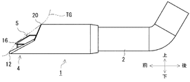
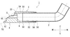
以下に、本発明の一実施形態に係る歯科診療用吸引具について、図面を参照して説明する。図1は、患者の唾液および血液、または冷却用噴水などの液体物質、または、切削屑などの固体物質を、患者の口腔内から吸引するために歯科診療用吸引具1と、歯科診療用吸引具1が取り付けられた吸引パイプ2とを示す。なお、図1に矢印で示す2つの方向を、上下方向および前後方向と定め、両方向と直交する方向を左右方向と定め、図2以降の他の図面でも同様に、各方向を示す。
<Embodiment>
Hereinafter, a suction tool for dental practice according to an embodiment of the present invention will be described with reference to the drawings. FIG. 1 shows a dental
歯科診療用吸引具1は、図示しない吸引ポンプに連結される吸引パイプ2に対して着脱可能に構成される。歯科診療用吸引具1は、加熱滅菌処理されることにより、繰り返し使用可能であるが、長期間使用された場合には、新品の歯科診療用吸引具1と交換される。
The dental
[歯科診療用吸引具1の詳細な構成]
図2乃至図6を参照して、歯科診療用吸引具1の詳細な構成を説明する。歯科診療用吸引具1は、合成樹脂材料から成形される。合成樹脂材料としては、耐熱性、耐薬品性、および可撓性に優れた合成樹脂材料であることが必要である。耐熱性として、130°Cから150°Cまでの加熱範囲で滅菌処理に耐えうることが必要であり、耐薬品性として、歯科治療に使用される薬品により劣化することがないことが必要である。合成樹脂材料として、シリコンゴム、または、熱可塑性エラストマーなどの合成樹脂材料が使用可能である。本実施形態では、三菱化学株式会社製のラバロン(登録商標)MJ5301Cが使用される。
[Detailed configuration of
With reference to FIG. 2 thru | or FIG. 6, the detailed structure of the dental
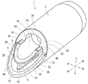
図2は、歯科診療用吸引具1単体の斜視図である。図2において、歯科診療用吸引具1は、筒状部3と、第1延出部4と、第2延出部5と、連結部6と、を主に備える。筒状部3は、円筒形状を有し、前後方向に延びて形成される。第1延出部4は、筒状部3の前方部分から、前方に延びて形成される。第1延出部4の外周面は、筒状部3の外周面と連続して形成される。第2延出部5は、第1延出部4の内部に配置された状態で、筒状部3および第1延出部4の前方部分から前方に延びて形成される。第1延出部4は、第1端縁部分10を備える、第1先端部分12は、その第1端縁部分10のうちで、最も前方に延出する部分である。第2延出部5は、第2端縁部分14を備える。第2先端部分16は、第2端縁部分14のうちで、最も前方に延出する部分である。本実施形態では、第1先端部分12は、第2先端部分16より、2.5mmだけ前方に延出する。第1先端部分12は、半径0.5mmの円弧面に形成され。第2先端部分16は、半径0.2mmの円弧面に形成される。
FIG. 2 is a perspective view of the dental
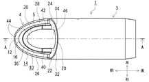
図3は、歯科診療用吸引具1の上面図であり、図4は、歯科診療用吸引具1の正面図である。図3において、筒状部3は、中心点CTを中心とする円形の外周面を有する。両延出部4、5の先端部分12、16は、図3および図4に示すように、中心点CTを通って上下方向に延びる平面であって、前後方向にも延びる特定の平面の上にそれぞれ位置するように、配置される。連結部6は、図4に示すように、特定の平面の上に位置する状態で、第1延出部4と、第2延出部5とを連結する。具体的には、連結部6は、図2に示すように、第2先端部分16の配置位置の近傍に、連結先端部分18を有し、その連結先端部分18から後方に延びる。
FIG. 3 is a top view of the dental
図2において、第1延出部4の第1端縁部分10は、筒状部3に最も近接した後端部分20と、右上傾斜部分22と、左上傾斜部分24と、右下傾斜部分26と、左下傾斜部分28と、を備える。右上傾斜部分22は、上方部分において後端部分20に連結されて形成され、下方部分において右下傾斜部分26に連結されて形成される。左上傾斜部分24は、上方部分において後端部分20に連結されて形成され、下方部分において左下傾斜部分28に連結されて形成される。右下傾斜部分26、および左下傾斜部分28は、下方部分において第1先端部分12に連結されて形成される。
In FIG. 2, the
図2において、第2延出部5の第2端縁部分14は、右上傾斜部分32と、左上傾斜部分34と、右下傾斜部分36と、左下傾斜部分38と、右水平部分40と、左水平部分42と、を備える。右水平部分40、および左水平部分42は、前後方向に水平に延びて形成される。右上傾斜部分32は、右側方部分において右上傾斜部分22に連結されて形成され、下方部分において右水平部分40の後端部分に連結されて形成される。左上傾斜部分34は、左側方部分において左上傾斜部分24に連結されて形成され、下方部分において左水平部分42の後端部分に連結されて形成される。右下傾斜部分36は、上方部分において右水平部分40の前端部分に連結されて形成され、下方部分において第2先端部分16に連結されて形成される。左下傾斜部分38は、上方部分において左水平部分42の前端部分に連結されて形成され、下方部分において第2先端部分16に連結されて形成される。
In FIG. 2, the second
第1延出部4の第1端縁部分10は、第1吸引開口44を形成する。第2延出部5の第2端縁部分14と、第1延出部4の右上傾斜部分22、および左上傾斜部分24の一部分とは、第2吸引開口46を形成する。第2吸引開口46は、図3および図4に示すように、第1吸引開口44の内部に形成される。筒状部3の中心点CTが、図4に示すように、第2吸引開口46の内部に位置するように、第2吸引開口46が形成される。
The
本実施形態では、第2吸引開口46が前後方向と直交する平面に投影された面積は、第1吸引開口44から第2吸引開口46を除いた残りの吸引開口が前後方向と直交する平面に投影された面積と、ほぼ同じ面積に設定される。その残りの吸引開口は、右下傾斜部分26と、左下傾斜部分28と、右下傾斜部分36と、左下傾斜部分38とにより、画定される。
In the present embodiment, the area where the second suction opening 46 is projected on the plane orthogonal to the front-rear direction is the plane where the remaining suction openings excluding the second suction opening 46 from the
第1延出部4の第1端縁部分10は、図4に示すように、中心点CTを中心とする円形の外周面を有する。その第1端縁部分10の円形の外周面は、筒状部3の円形の外周面と同じ半径で、形成される。第2延出部5の第2端縁部分14の右下傾斜部分36、および左下傾斜部分38は、中心点CTから上方に偏心した中心点CHを中心とする円弧形状に形成される。第2端縁部分14の右上傾斜部分32、および左上傾斜部分34を前方から見た形状は、図4に示すように、右水平部分40、および左水平部分42から直線状に立ち上がる形状である。
As shown in FIG. 4, the
(第1延出部4の第1端縁部分10の傾斜形状)
第1延出部4の第1端縁部分10の傾斜形状について、図5および図6を参照して説明する。図5は、歯科診療用吸引具1の右側面図であり、図6は、図3に示すA−A線に従って切断された歯科診療用吸引具1の右側断面図である。図5において、中心線CLは、中心点CTを通り、前後方向に延びる線である。傾斜線KL1は、後端部分20と第1先端部分12とを結ぶ線である。傾斜線KL2は、後端部分20と第2先端部分16とを結ぶ線である。傾斜角度θ1は、傾斜線KL1と、前後方向の水平線とが時計回り方向になす角度である。傾斜角度θ2は、傾斜線KL2と、前後方向の水平線とが時計回り方向になす角度である。傾斜角度α1は、右上傾斜部分22が、中心線CLを含む上下方向の垂直な平面に投影された傾斜線と、前後方向の水平線とが時計回り方向になす角度である。傾斜角度α2は、右下傾斜部分26が、中心線CLを含む上下方向の垂直な平面に投影された傾斜線と、前後方向の水平線とが時計回り方向になす角度である。
(Inclined shape of the
An inclined shape of the first
図6において、傾斜角度α1は、左上傾斜部分24が、中心線CLを含む上下方向の垂直な平面に投影された傾斜線と、前後方向の水平線とが時計回り方向になす角度である。傾斜角度α2は、左下傾斜部分28が、中心線CLを含む上下方向の垂直な平面に投影された傾斜線と、前後方向の水平線とが時計回り方向になす角度である。本実施形態では、傾斜角度θ1は、41度に設定され、傾斜角度θ2は、37度に設定される。傾斜角度α1は、67度に設定され、傾斜角度α2は、27度に設定される。すなわち、傾斜角度α1は、傾斜角度θ1より大きく設定されるとともに、傾斜角度α2は、傾斜角度θ1より小さく設定される。これらの傾斜角度の設定により、右上傾斜部分22と、右下傾斜部分26とにより形成される傾斜部分は、傾斜線KL1を含む左右方向の平面との間で、所定の間隙を形成することができる。同様に、左上傾斜部分24と、左下傾斜部分28とにより形成される傾斜部分は、傾斜線KL1を含む左右方向の平面との間で、所定の間隙を形成することができる。
In FIG. 6, the inclination angle α1 is an angle formed by the upper left inclined
右上傾斜部分22と、右下傾斜部分26とが連結される右連結部分は、図5に示すように、上下方向において、中心線CLとほぼ同じ位置に位置する。同様に、左上傾斜部分24と、左下傾斜部分28とが連結される左連結部分は、上下方向において、中心線CLとほぼ同じ位置に位置する。図4においては、右連結部分、および左連結部分は、中心点CTを通る左右方向の水平線の上に、ほぼ位置する。
The right connecting portion where the upper right inclined
(第2延出部5の第2端縁部分14の傾斜形状)
第2延出部5の第2端縁部分14の傾斜形状について、図5および図6を参照して説明する。図5において、傾斜角度β1は、右上傾斜部分32が、中心線CLを含む上下方向の垂直な平面に投影された傾斜線と、前後方向の水平線とが時計回り方向になす角度である。傾斜角度β2は、右下傾斜部分36が、中心線CLを含む上下方向の垂直な平面に投影された傾斜線と、前後方向の水平線とが時計回り方向になす角度である。
(Inclined shape of the
The inclined shape of the second
図6において、傾斜角度β1は、左上傾斜部分34が、中心線CLを含む上下方向の垂直な平面に投影された傾斜線と、前後方向の水平線とが時計回り方向になす角度である。傾斜角度β2は、左下傾斜部分38が、中心線CLを含む上下方向の垂直な平面に投影された傾斜線と、前後方向の水平線とが時計回り方向になす角度である。本実施形態では、傾斜角度β1は、67度に設定され、傾斜角度α1と同じ角度に設定される。傾斜角度β2は、29度に設定される。すなわち、傾斜角度θ2は、傾斜角度θ1より小さく設定される。傾斜角度β1は、傾斜角度θ2より大きく設定されるとともに、傾斜角度β2は、傾斜角度θ2より小さく設定される。これらの傾斜角度の設定により、右上傾斜部分32と、右水平部分40と、右下傾斜部分36とにより形成される傾斜部分は、傾斜線KL2を含む左右方向の平面との間で、所定の間隙を形成することができる。同様に、左上傾斜部分34と、左水平部分42と、左下傾斜部分38とにより形成される傾斜部分は、傾斜線KL2を含む左右方向の平面との間で、所定の間隙を形成することができる。
In FIG. 6, the inclination angle β1 is an angle formed by the upper left inclined
(第2延出部5の第2先端部分16の延出形状)
図5において、第2延出部5の第2先端部分16は、傾斜線KL1に対して、前方に延出した位置に配置される。また、第2先端部分16は、第1先端部分12より退避した位置、すなわち後方の位置に配置される。第2先端部分16と中心線CLとの間の距離が、右水平部分40、および左水平部分42の各水平部分と中心線CLとの間の距離と、ほぼ同じになるように、右下傾斜部分36、および左下傾斜部分38が中心線CLに対して配置される。
(Extension shape of the
In FIG. 5, the 2nd front-end | tip
本実施形態では、傾斜角度α2は、27度に設定され、傾斜角度β2は、傾斜角度θ2の37度より小さい角度である29度に設定される。傾斜角度α2と、傾斜角度β2とは、ほぼ同じ角度に設定される。これらの傾斜角度の設定状態において、右下傾斜部分36の1/2以上の傾斜部分が、図5に示すように、傾斜線KL1に対して前方に延出するように、右水平部分40の前後方向の長さが設定される。同様に、左下傾斜部分38の1/2以上の傾斜部分が、傾斜線KL1に対して前方に延出するように、左水平部分42の前後方向の長さが設定される。
In the present embodiment, the inclination angle α2 is set to 27 degrees, and the inclination angle β2 is set to 29 degrees that is smaller than 37 degrees of the inclination angle θ2. The inclination angle α2 and the inclination angle β2 are set to substantially the same angle. In the setting state of these inclination angles, the right
本実施形態では、筒状部3の外周面の直径は、12.1mmに設定される。第1先端部分12は、後端部分20から前方に、13.0mmだけ延出する。第2先端部分16は、後端部分20から前方に、10.5mmだけ延出する。右下傾斜部分26が、中心線CLを含む上下方向の垂直な平面に投影された傾斜線と、右下傾斜部分36が、中心線CLを含む上下方向の垂直な平面に投影される傾斜線との間の間隔は、約2.2mmに設定される。同様に、左下傾斜部分28が、中心線CLを含む上下方向の垂直な平面に投影された傾斜線と、左下傾斜部分38が、中心線CLを含む上下方向の垂直な平面に投影される傾斜線との間の間隔も、約2.2mmに設定される。
In this embodiment, the diameter of the outer peripheral surface of the
(筒状部3の内部構成)
図6において、筒状部3は、後方内周部50と、中間内周部52と、前方内周部54と、を備える。3つの内周部50〜54は、中心線CLに直交する平面において円形の断面形状をそれぞれ有する。挿入開口56が、後方内周部50の後端部分に形成される。吸引パイプ2は、挿入開口56から、筒状部3の内部に挿入される。中間内周部52は、後方部分において後方内周部50の前方部分に連結される。挿入開口56は、直径D1を有し、中間内周部52は、直径D1より小さい直径D2を有する内周面により形成される。このため、後方内周部50は、挿入開口56から、中間内周部52との連結部分まで、円形の断面形状の直径が徐々に小さくなるテーパ形状の内周面により形成される。吸引パイプ2の外周面の直径は、挿入開口56の直径D1より小さく設定される。また、吸引パイプ2の外周面の直径は、中間内周部52の内周面の直径D2より、僅かに大きい。この中間内周部52の内周面の直径D2の設定により、吸引パイプ2を挿入する際に、中間内周部52は弾性変形して吸引パイプ2の挿入状態を保持する。
(Internal structure of the cylindrical part 3)
In FIG. 6, the
中間内周部52は、直径D2を有する円形の断面形状の内周面により形成される。前方内周部50は、直径D3を有する円形の断面形状の内周面により形成される。直径D3は、直径D2より小さく設定される。この直径の設定により、段差部分58が、中間内周部52と前方内周部54とが連結される位置に形成される。3つの内周部50〜54の内周面は、唾液、または切削屑などの物質が吸引される吸引内部空間を形成する。第1吸引開口44、および第2吸引開口46は、この吸引内部空間に連通する。
The intermediate inner
図6において、第2延出部5は、第2端縁部分14から、固定端部分60まで後方に延びて形成される。固定端部分60を含む第2延出部5の後方部分は、前方内周部54の内周面に連結される。
In FIG. 6, the second extending
(連結部6の形成範囲)
図6において、連結部6は、連結先端部分18から、連結後端部分60まで後方に延びて形成される。連結後端部分60を含む連結部6の後方部分は、前方内周部54の内周面に連結される。連結後端部分60は、前後方向において、第2延出部5の固定端部分60と同じ位置に配置される。
(Formation range of connecting portion 6)
In FIG. 6, the connecting
図6において、領域REは、前後方向において、第2延出部5の第2先端部分16から、固定端部分60までの形成領域である。領域RCは、連結部6の連結先端部分18が配置される前後方向の領域である。間隔Hは、第2延出部5の第2先端部分16において、第1延出部4と第2延出部5との間の互いに対向する面の間隔である。具体的には、図4に示す中心点CTからの放射方向において、右下傾斜部分36、および左下傾斜部分38の外周面と、右下傾斜部分26、および左下傾斜部分28の内周面との間の間隔のうちで、最大の間隔が、間隔Hである。領域RCは、間隔Hと同じ長さの領域である。
In FIG. 6, a region RE is a formation region from the
本実施形態では、連結先端部分18が、領域RCの範囲内に配置される。この連結先端部分18の配置により、連結先端部分18に近接する第2延出部5の一部分が上方から押圧されて下方に湾曲した場合でも、右下傾斜部分36、および左下傾斜部分38の外周面と、右下傾斜部分26、および左下傾斜部分28の内周面との間に形成される吸引開口が塞がれることを防止することができる。
In the present embodiment, the connecting
(歯科診療用吸引具1の各部分の肉厚)
図6において、第1延出部4の右下傾斜部分26の肉厚T1、および左下傾斜部分28の肉厚T1は、第2延出部5の右下傾斜部分36の肉厚T2、および左下傾斜部分38の肉厚T2と、ほぼ同じ肉厚か、または、僅かに小さい肉厚に設定される。また、前方内周部54における筒状部3の肉厚T3は、肉厚T1と同じ肉厚に設定される。本実施形態では、肉厚T1、T3は、1.5mmに設定される。
(Thickness of each part of the
In FIG. 6, the thickness T1 of the lower right inclined
[実施形態の動作および作用]
歯科診療用吸引具1の動作および作用を簡単に説明する。歯科診療用吸引具1の動作および作用として、吸引パイプ2に対する歯科診療用吸引具1の取付け動作、および取外し動作と、歯科診療用吸引具1により唾液などの物質を吸引する動作とを、以下に説明する。
[Operation and Action of Embodiment]
The operation and action of the dental
(吸引パイプ2に対する歯科診療用吸引具1の取付け動作、および取外し動作)
新品の歯科診療用吸引具1を吸引パイプ2に取り付ける場合、図6において、使用者が、歯科診療用吸引具1の挿入開口56から、吸引パイプ2の先端部分を内部に挿入する。吸引パイプ2の直径は、挿入開口56の直径D1より小さいことから、使用者は、後方内周部50において吸引パイプ2の先端部分を小さな挿入力で挿入することができる。
(Attachment operation and removal operation of the
When the new dental
吸引パイプ2の外周面の直径は、中間内周部52の内周面の直径D2より、僅かに大きいことから、使用者は、中間内周部52において、後方内周部50における挿入力より大きな挿入力で吸引パイプ2の先端部分を挿入する必要がある。この挿入の際に、筒状部3の中間内周部52は弾性変形することにより、その中間内周部52の内周面の直径が吸引パイプ2の外周面の直径に合わせて大きくなる。
Since the diameter of the outer peripheral surface of the
使用者が、吸引パイプ2の先端部分が段差部分58に当接するまで吸引パイプ2を挿入すると、吸引パイプ2に対する歯科用吸引チップ1の前後方向の位置が決定される。この段部分58への当接により、吸引パイプ2の挿入作業が終了し、歯科診療用吸引具1が吸引パイプ2に取り付けられる。
When the user inserts the
新品の歯科診療用吸引具1と交換するために、吸引パイプ2から歯科診療用吸引具1を取り外す場合、使用者は、吸引パイプ2の外周面と中間内周部52の内周面との間の摩擦抵抗に抗して、吸引パイプ2から古い歯科診療用吸引具1を引き抜く作業を行う。
When the dental
(歯科診療用吸引具1により唾液などの物質を吸引する動作)
歯科診療用吸引具1を患者の治療のために使用する前に、歯科診療用吸引具1単体、または、所定の長さの吸引パイプ2に取り付けた状態の歯科診療用吸引具1が加熱滅菌処理される。図示しない吸引ポンプを作動させると、吸引パイプ2の内部、および筒状部3の吸引内部空間が負圧の状態になる。この負圧の状態において、歯科診療用吸引具1が患者の口腔内に挿入されると、唾液、および冷却用噴水などの液体物質、または切削屑などの固体物質が、第2延出部5の第2吸引開口46と、その第2吸引開口46以外の第1延出部4の第1吸引開口44とから吸引され、筒状部3の吸引内部空間に吸い込まれる。一般的には、口腔内の下方に溜まる唾液などを吸引するために、図1、および図7に示すように、第1延出部4の第1先端部分12が口腔内の下方に位置するように、歯科診療用吸引具1が挿入される。図1、および図7において、舌、または頬などの柔らかい組織TGが、二点鎖線で示される。
(Operation for sucking saliva and other substances with the dental care suction tool 1)
Before using the dental
歯科診療用吸引具1が口腔内の奥まで挿入されると、歯科診療用吸引具1の第1延出部4、および第2延出部5が患者の柔らかい組織TGに接触する場合が多く発生する。この場合、その柔らかい組織TGの表面が第1吸引開口44、および第2吸引開口46に向かって吸引される。しかし、第2延出部5の第2先端部分16が、図5および図6に示すように、傾斜線KL1より前方に延出して配置されることから、柔らかい組織TGの表面は第2先端部分16に当たって、第1端縁部分10、および第2端縁部分14まで吸い寄せられることが低減される。具体的には、柔らかい組織TGの表面は第2先端部分16に当たることにより、柔らかい組織TGの表面が、第1端縁部分10の右上傾斜部分22、左上傾斜部分24、右下傾斜部分26、および左下傾斜部分28に接触することが低減されるとともに、第2端縁部分14の右上傾斜部分32、左上傾斜部分34、右下傾斜部分36、および左下傾斜部分38に接触することが低減される。
When the dental
第2延出部5の第2先端部分16の近傍部分は、連結部6により、第1延出部4の第1先端部分12の近傍部分と連結されることから、第2延出部5の第2先端部分16が柔らかい組織TGの表面に当たった場合でも、第2延出部5の第2先端部分16の近傍部分が弾性変形して下方に移動することが低減される。この下方への移動が低減されることにより、第2先端部分16が傾斜線KL1より前方に延出した状態が保持される。また、第2延出部5は可撓性に優れた合成樹脂材料から形成されることから、右下傾斜部分36、および左下傾斜部分38のうちで第2先端部分16から離れた部分は、柔らかい組織TGと接触して弾性変形することから、第2延出部5が患者に違和感を与えることは少ない。
Since the vicinity of the
第2延出部14の右上傾斜部分32、および左上傾斜部分34の傾斜角度β1は、右下傾斜部分36、および左下傾斜部分38の傾斜角度β2より大きく設定される。また、第2延出部14は、右水平部分40、および左水平部分42を備える。第2延出部5の両傾斜部分32、34、および両水平部分40、42は、図5、および図6に示すように、傾斜線KL2の後方に、間隙を確保するために作用する。
The inclination angle β1 of the upper right inclined
[実施形態の効果]
本実施形態では、第2延出部5の第2先端部分16が、図5および図6に示すように、傾斜線KL1より前方に延出して配置されることから、柔らかい組織TGの表面は第2先端部分16に当たって、第1端縁部分10、および第2端縁部分14まで吸い寄せられることが低減される。この結果、第1吸引開口44、および第2吸引開口46が柔らかい組織TGの表面により塞がれることが低減され、両吸引開口44、46からの物質の吸引作用が継続される。
[Effect of the embodiment]
In the present embodiment, as shown in FIGS. 5 and 6, the second
本実施形態では、第2延出部5の第2先端部分16の近傍部分は、連結部6により、第1延出部4の第1先端部分12の近傍部分と連結されることから、第2延出部5の第2先端部分16が柔らかい組織TGの表面に当たった場合でも、第2延出部5の第2先端部分16の近傍部分が弾性変形して下方に移動することが低減される。この結果、第1吸引開口44、および第2吸引開口46が柔らかい組織TGの表面により塞がれることが低減され、両吸引開口44、46からの物質の吸引作用が確実に継続される。
In the present embodiment, the vicinity of the
本実施形態では、領域RCは、図6に示す両延出部4、5の間隔Hと同じ距離に設定される。連結部6の連結先端部分18が、図6に示すように、第2先端部分16から領域RCの範囲内に配置される。この結果、第2先端部分16が柔らかい組織TGに当たって下方に湾曲して弾性変形したとしても、第2先端部分16の下方に位置する第1吸引開口44が第2先端部分16の近傍部分により塞がれることが確実に防止される。
In the present embodiment, the region RC is set to the same distance as the distance H between the extending
本実施形態では、第2延出部5の両傾斜部分32、34、および両水平部分40、42は、図5、および図6に示すように、傾斜線KL2の後方に、間隙を確保するために作用する。この結果、第2吸引開口46が柔らかい組織TGの表面により塞がれることが低減され、この吸引開口46からの物質の吸引作用が確実に継続される。
In the present embodiment, as shown in FIGS. 5 and 6, the
本実施形態では、第2延出部5は、両水平部分40、42を備えることから、第2先端部分16を傾斜線KL1より前方に延出するように配置するために右下傾斜部分26、および左下傾斜部分28の傾斜角度を小さな角度に設定する必要がない。この結果、両傾斜部分36、38の傾斜角度β2を第1延出部4の両傾斜部分26、28の傾斜角度α2とほぼ同じ角度に設定することができ、第2先端部分16が柔らかい組織TGに接触した場合でも、患者に違和感を与えることが低減される。
In the present embodiment, since the second extending
本実施形態では、図4に示すように、第2吸引開口46が、その第2吸引開口46以外の第1吸引開口44より上方に配置される。連結部6は、第2吸引開口46以外の第1吸引開口44の内部に配置される。一般的に、唾液などの液体物質は患者の口腔内の下方に溜まることから、連結部6は、液体物質の吸引に支障となることはない。一方、歯の切削屑などの固体物質は、第1延出部4の両傾斜部分26、28より上方に位置する第2延出部5の両傾斜部分36、38の上に落ちることが多いと考えられることから、この固体物質は、第2吸引開口46から吸引されて、筒状部3の吸引内部空間に円滑に移動される。
In the present embodiment, as shown in FIG. 4, the second suction opening 46 is disposed above the first suction opening 44 other than the
<構成の対応関係>
歯科診療用吸引具1は、本発明の診療用吸引具の一例である。吸引パイプ2が、本発明の吸引パイプの一例である。筒状部3、第1延出部4、第2延出部5、および連結部6は、本発明の筒状部、第1延出部、第2延出部、および連結部の一例である。第1端縁部分10、および第2端縁部分12が、本発明の第1端縁部分、および第2端縁部分の一例である。第1吸引開口44、および第2吸引開口46が、本発明の第1吸引開口、および第2吸引開口の一例である。後方内周部50、中間内周部52、および前方内周部54の内周面が形成する空間が、本発明の筒状部の内部空間の一例である。前方内周部54の内周面が、本発明の筒状部の内周面の一例である。第1先端部分12が、本発明の第1端縁部分のうちの最も延出する先端部分の一例である。第2先端部分16が、本発明の第2端縁部分のうちの最も延出する先端部分の一例である。後端部分20が、本発明の第1端縁部分のうちの最も筒状部に近接する端縁部分の一例である。傾斜線KL1が、本発明の「第1端縁部分のうちの最も筒状部に近接する端縁部分と、第1端縁部分のうちの最も延出する先端部分とを結ぶ線分」の一例である。第1端縁部分10の右上傾斜部分22、および左上傾斜部分24が、本発明の第1傾斜部分の一例であり、第1端縁部分10の右下傾斜部分26、および左下傾斜部分28が、本発明の第2傾斜部分の一例である。傾斜角度α1は、本発明の第1傾斜部分の一例である。傾斜角度θ1は、本発明の「第1端縁部分のうちの最も筒状部に近接する端縁部分と、第1端縁部分のうちの最も延出する先端部分とを結ぶ線分の所定の延出方向に対する傾斜角度」の一例である。第2端縁部分14の右上傾斜部分32、および左上傾斜部分34が、本発明の第3傾斜部分の一例であり、第2端縁部分14の右下傾斜部分36、および左下傾斜部分38が、本発明の第4傾斜部分の一例である。傾斜角度β1、および傾斜角度β2は、本発明の第3傾斜部分の傾斜角度、および第4傾斜部分の傾斜角度の一例である。挿入開口56、および段差部分58が、本発明の挿入開口、および段差部分の一例である。間隔Hは、本発明の「第2端縁部分のうちの最も延出する先端部分において所定の延出方向と直交する方向に第1延出部と第2延出部とが離間する間隔」の一例である。領域RCは、本発明の「第2端縁部分のうちの最も延出する先端部分から所定の延出方向に定められる範囲」の一例である。中心点CTが、本発明の筒状部の内部空間の中心位置の一例である。前後方向が、本発明の所定の長手方向、および、所定の延出方向の一例である。
<Correspondence of configuration>
The dental
<変形例>
本発明は、本実施形態に限定されることはなく、その趣旨を逸脱しない範囲において種々の変形が可能である。以下にその変形の一例を述べる。
<Modification>
The present invention is not limited to this embodiment, and various modifications can be made without departing from the spirit of the present invention. An example of the modification will be described below.
(1)本実施形態は、本発明を歯科診療用吸引具1に具体化した形態であるが、この形態に限定されない。たとえば、心臓手術などの医療手術を行うために血液などの物質を吸引する外科手術用吸引具として、本発明が具体化されてもよい。この場合、手術される患者の部位に応じて、筒状部の直径、第1延出部および第2延出部の延出長さ、および第1延出部および第2延出部の傾斜形状などが決定される。また、筒状部、および両延出部を形成する合成樹脂材料の種類も、手術される患者の部位の組織の柔らかさなどの組織の特性、および、使用される薬品に応じて、決定される。
(1) Although the present embodiment is a form in which the present invention is embodied in the dental
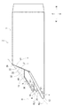
(2)本実施形態では、吸引パイプ2の外周面が、筒状部3の中間内周部52の内周面に密着した状態で嵌合することにより、吸引パイプ2に対する歯科診療用吸引具1の取付状態が保持される。その取付状態を保持する保持力、すなわち、吸引パイプ2の外周面と中間内周部52の内周面との間の摩擦抵抗が大きい場合には、吸引パイプ2から歯科診療用吸引具1が抜け落ちるおそれが低くなるが、逆に、歯科診療用吸引具を交換するために、吸引パイプ2から歯科診療用吸引具1を取り外す際に、取り外すのに苦労することがある。そこで、図8に示す変形例では、一対の把持突起70、72が、筒状部3の外周面に固定して設けられる。両把持突起70、72の前後方向の長さは、使用者が筒状部3の外周面を確実に把持して吸引パイプ2に対して歯科診療用吸引具1を前後方向に移動させるのに必要な長さに設定される。本変形例では、2つの把持突起70、72が設けられるが、3つ以上の把持突起が設けられてもよい。また、両把持突起70、72は、前後方向に延びた状態で設けられるが、複数の把持突起が、筒状部3の外周面の円周方向に延びた状態で設けられてもよい。使用者は、複数の把持突起により筒状部3の外周面を確実に把持することができることから、吸引パイプ2に取り付けられた歯科診療用吸引具1を、吸引パイプ2に対して回動させることが容易になる。このため、診療途中において、吸引パイプ2に対する歯科診療用吸引具1の回動位置を調整することができる。
(2) In the present embodiment, the suction pipe for dental treatment with respect to the
(3)本実施形態では、第1端縁部分10の右上傾斜部分22、および左上傾斜部分24の傾斜角度α1と、第2端縁部分14の右上傾斜部分32、および左上傾斜部分34の傾斜角度β1とが、同じ傾斜角度に設定されるが、両傾斜角度α1、β1が、異なる角度であってもよい。
(3) In the present embodiment, the inclination angle α1 of the upper right inclined
(4)本実施形態では、第2端縁部分14は、右水平部分40、および左水平部分42を備え、第1端縁部分10は、水平部分を備えない構成であるが、この構成に限定される。たとえば、両端縁部分がともに、水平部分を備える構成であってもよいし、第1端縁部分のみが水平部分を備える構成であってもよい。
(4) In the present embodiment, the second
(5)本実施形態では、第1端縁部分10の右下傾斜部分26の内周面、および左下傾斜部分28の内周面と、第2端縁部分14の右下傾斜部分36の外周面、および左下傾斜部分88の外周面との間の間隔が最も大きな間隔となる位置のみに、図4に示すように、連結部6が配置される構成であるが、この構成に限定されない。たとえば、中心点CTを中心とする複数の異なる回動位置において、第1端縁部分10の上記内周面と第2端縁部分14の上記外周面との間に、複数の連結部が設けられる構成であってもよい。
(5) In this embodiment, the inner peripheral surface of the lower right inclined
(6)本実施形態では、第2延出部5の第2端縁部分14の右下傾斜部分36、および左下傾斜部分38は、中心点CTから上方に偏心した中心点CHを中心とする円弧形状に形成される。第2端縁部分14の右上傾斜部分32、および左上傾斜部分34を前方から見た形状は、図4に示すように、右水平部分40、および左水平部分42から直線状に立ち上がる形状である。第2端縁部分14を前方から見た形状は、図4に示す形状に限定されない。たとえば、第2端縁部分14を前方から見た形状は、中心点CTから偏心した中心点を中心とする連続した円弧形状であってもよいし、円形形状であってもよい。
(6) In the present embodiment, the lower right inclined
(7)本実施形態では、図4において、右上傾斜部分32は、右側方部分において右上傾斜部分22に連結されて形成される。左上傾斜部分34は、左側方部分において左上傾斜部分24に連結されて形成される。図6において、第2延出部5は、第2端縁部分14から、固定端部分60まで後方に延びて形成される。固定端部分60を含む第2延出部5の後方部分は、前方内周部54の内周面に連結される。すなわち、第2延出部5は、筒状部3の内周面、および第1延出部4の内周面にそれぞれ連結される構成であるが、この構成に限定されない。たとえば、第2延出部5は、筒状部3の内周面、および第1延出部4の内周面のいずれか一方の内周面に連結される構成であってもよい。
(7) In the present embodiment, in FIG. 4, the upper right inclined
(8)本実施形態では、傾斜角度β1は、67度に設定され、傾斜角度α1と同じ角度に設定される。傾斜角度α2は、27度に設定され、傾斜角度β2は、傾斜角度θ2の37度より小さい角度である29度に設定される。傾斜角度α2と、傾斜角度β2とは、ほぼ同じ角度に設定される。これらの傾斜角度α1、α2、β1、β2の設定は、本実施形態における傾斜角度の設定に限定されない。たとえば、第2端縁部分14は、第1端縁部分10の前下がりの傾斜方向に沿って、前下がりに傾斜して延びる構成であるかぎり、傾斜角度α1、β1が異なるとともに、傾斜角度α2、β2が異なるように設定されてもよい。
(8) In the present embodiment, the inclination angle β1 is set to 67 degrees, and is set to the same angle as the inclination angle α1. The inclination angle α2 is set to 27 degrees, and the inclination angle β2 is set to 29 degrees, which is an angle smaller than 37 degrees of the inclination angle θ2. The inclination angle α2 and the inclination angle β2 are set to substantially the same angle. The setting of these inclination angles α1, α2, β1, and β2 is not limited to the setting of the inclination angles in the present embodiment. For example, as long as the
1 歯科診療用吸引具
2 吸引パイプ
3 筒状部
4 第1延出部
5 第2延出部
6 連結部
10 第1端縁部分
12 第1先端部分
14 第2端縁部分
16 第2先端部分
20 後端部分
22、32 右上傾斜部分
24、34 左上傾斜部分
26、36 右下傾斜部分
28、38 左下傾斜部分
44 第1吸引開口
46 第2吸引開口
50 後方内周部
52 中間内周部
54 前方内周部
56 挿入開口
58 段差部分
KL1、KL2 傾斜線
θ1、θ2、α1、α2、β1、β2 傾斜角度
H 間隔
RC 領域
DESCRIPTION OF
Claims (10)
唾液、または切削屑などの物質を体内から吸引するための第1吸引開口を形成する第1端縁部分を有し、第1吸引開口が内部空間に連通するように筒状部から所定の長手方向と平行な所定の延出方向に延びる第1延出部と、
唾液、または切削屑などの物質を体内から吸引するための第2吸引開口を第1吸引開口の内部に形成する第2端縁部分を有し、第2吸引開口が内部空間に連通するように所定の延出方向に延び、筒状部の内周面、または第1延出部の内周面に連結される第2延出部と、
所定の延出方向と直交する方向において、第1延出部と第2延出部との間の互いに対向する面を連結する連結部と、を備え、
第1端縁部分は、第1端縁部分のうちの最も筒状部に近接する端縁部分から、第1端縁部分のうちの最も延出する先端部分まで、所定の延出方向に対して傾斜して延び、
第2端縁部分は、第1端縁部分の傾斜方向に沿って所定の延出方向に対して傾斜して延び、
第2端縁部分のうちの最も延出する先端部分は、所定の延出方向において、第1端縁部分のうちの最も筒状部に近接する端縁部分と、第1端縁部分のうちの最も延出する先端部分とを結ぶ線分よりも、延出した位置であって、第1端縁部分のうちの最も延出する先端部分よりも、退避した位置に配置される診療用吸引具。 A cylindrical portion having an internal space and extending in a predetermined longitudinal direction;
It has a first edge portion that forms a first suction opening for sucking a substance such as saliva or cutting waste from the body, and has a predetermined length from the cylindrical portion so that the first suction opening communicates with the internal space. A first extension portion extending in a predetermined extension direction parallel to the direction;
A second suction opening for forming a second suction opening for sucking a substance such as saliva or cutting waste from the body is formed inside the first suction opening so that the second suction opening communicates with the internal space. A second extending portion extending in a predetermined extending direction and connected to the inner peripheral surface of the cylindrical portion or the inner peripheral surface of the first extending portion;
In a direction orthogonal to the predetermined extending direction, a connecting portion that connects the mutually facing surfaces between the first extending portion and the second extending portion, and
The first edge portion is in a predetermined extending direction from the edge portion closest to the tubular portion of the first edge portion to the most extended tip portion of the first edge portion. And extend
The second edge portion extends with an inclination with respect to a predetermined extending direction along the inclination direction of the first edge portion,
The most extended tip portion of the second edge portion is, in a predetermined extending direction, of the edge portion closest to the tubular portion of the first edge portion and the first edge portion. The medical suction is located at a position extending from a line segment connecting the most extended tip portion of the first end edge portion and at a position retracted from the most extending tip portion of the first edge portion. Ingredients.
第1端縁部分のうちの最も筒状部に近接する端縁部分と、第1端縁部分のうちの最も延出する先端部分とを結ぶ線分の所定の延出方向に対する傾斜角度は、第1傾斜部分の傾斜角度より小さく設定される請求項1乃至請求項4のいずれかに記載の診療用吸引具。 The first end portion of the first extending portion includes a first inclined portion including an end edge portion closest to the cylindrical portion, and a first inclined portion having an inclination angle smaller than the first inclined portion and including the most extended tip portion. Two inclined portions,
An inclination angle with respect to a predetermined extending direction of a line segment connecting an edge part closest to the cylindrical part of the first edge part and a tip part extending most of the first edge part is: The medical suction tool according to any one of claims 1 to 4, wherein the medical suction tool is set to be smaller than an inclination angle of the first inclined portion.
第1端縁部分のうちの最も筒状部に近接する端縁部分と、第1端縁部分のうちの最も延出する先端部分とを結ぶ線分の所定の延出方向に対する傾斜角度は、第3傾斜部分の傾斜角度より小さく、第4傾斜部分の傾斜角度より大きく設定される請求項5に記載の診療用吸引具。 The second end portion of the second extending portion includes a third inclined portion including an inner peripheral surface of the cylindrical portion or an end portion connected to the inner peripheral surface of the first extending portion, and a third inclined portion. A fourth inclined portion having a smaller inclination angle and including the most extended tip portion;
An inclination angle with respect to a predetermined extending direction of a line segment connecting an edge part closest to the cylindrical part of the first edge part and a tip part extending most of the first edge part is: The medical suction tool according to claim 5, wherein the medical suction tool is set to be smaller than an inclination angle of the third inclined portion and larger than an inclination angle of the fourth inclined portion.
所定の延出方向と直交する平面において、筒状部の内周面、または第1延出部の内周面と、その内周面に対向する第2延出部の内周面とにより画定される領域に、筒状部の内部空間の中心位置が位置するように、第2延出部が配置される請求項1乃至請求項6のいずれかに記載の診療用吸引具。 The internal space of the cylindrical portion has a circular cross-sectional shape in a plane orthogonal to a predetermined extending direction,
In a plane orthogonal to the predetermined extending direction, the inner peripheral surface of the cylindrical portion or the inner peripheral surface of the first extending portion and the inner peripheral surface of the second extending portion facing the inner peripheral surface are defined. The medical suction tool according to any one of claims 1 to 6, wherein the second extending portion is disposed so that the center position of the internal space of the cylindrical portion is located in the region to be formed.
段差部分は、挿入開口から挿入される吸引パイプの端縁と当接可能に形成される請求項1乃至請求項8のいずれかに記載の診療用吸引具。 The cylindrical portion is inserted with a suction pipe connected to the suction force generating means, and has an insertion opening communicating with the internal space, and a step portion.
The medical suction tool according to any one of claims 1 to 8, wherein the step portion is formed so as to be able to contact an end edge of a suction pipe inserted from the insertion opening.
複数の把持突起が、所定の延出方向と直交する方向に、筒状部の外周面から突出する請求項1乃至請求項9のいずれかに記載の診療用吸引具。 The cylindrical portion is inserted with a suction pipe connected to the suction force generating means, and has an insertion opening communicating with the internal space.
The medical suction tool according to any one of claims 1 to 9, wherein the plurality of gripping protrusions protrude from the outer peripheral surface of the cylindrical portion in a direction orthogonal to a predetermined extending direction.
Priority Applications (1)
| Application Number | Priority Date | Filing Date | Title |
|---|---|---|---|
| JP2015125161A JP6485908B2 (en) | 2015-06-22 | 2015-06-22 | Medical suction tool |
Applications Claiming Priority (1)
| Application Number | Priority Date | Filing Date | Title |
|---|---|---|---|
| JP2015125161A JP6485908B2 (en) | 2015-06-22 | 2015-06-22 | Medical suction tool |
Publications (2)
| Publication Number | Publication Date |
|---|---|
| JP2017006385A true JP2017006385A (en) | 2017-01-12 |
| JP6485908B2 JP6485908B2 (en) | 2019-03-20 |
Family
ID=57762122
Family Applications (1)
| Application Number | Title | Priority Date | Filing Date |
|---|---|---|---|
| JP2015125161A Active JP6485908B2 (en) | 2015-06-22 | 2015-06-22 | Medical suction tool |
Country Status (1)
| Country | Link |
|---|---|
| JP (1) | JP6485908B2 (en) |
Citations (9)
| Publication number | Priority date | Publication date | Assignee | Title |
|---|---|---|---|---|
| JPH0475512U (en) * | 1990-11-14 | 1992-07-01 | ||
| US5165891A (en) * | 1991-01-18 | 1992-11-24 | Rily Young | High-volume ejector with valves and spacing fin |
| JPH08117257A (en) * | 1994-10-26 | 1996-05-14 | Toppan Printing Co Ltd | Aspirator for dental examination |
| US5690487A (en) * | 1995-04-07 | 1997-11-25 | White Shield Inc. | Disposable oral suction tip |
| JP2004321710A (en) * | 2003-04-28 | 2004-11-18 | Toi Sangyo Kk | Elastic suction chip used for suction machine |
| JP2005137865A (en) * | 2003-11-10 | 2005-06-02 | Shigeru Sasaki | Anti-fogging stomatoscope with suction function |
| JP2007289243A (en) * | 2006-04-21 | 2007-11-08 | Futoshi Shioda | Suction tip |
| US20090317760A1 (en) * | 2008-06-20 | 2009-12-24 | Anthony Michael Gadbois | Multi-lumen aspirator device |
| JP2014184097A (en) * | 2013-03-25 | 2014-10-02 | J Morita Tokyo Mfg Corp | Attachment member, suction instrument, tubular member, and medical care device |
-
2015
- 2015-06-22 JP JP2015125161A patent/JP6485908B2/en active Active
Patent Citations (9)
| Publication number | Priority date | Publication date | Assignee | Title |
|---|---|---|---|---|
| JPH0475512U (en) * | 1990-11-14 | 1992-07-01 | ||
| US5165891A (en) * | 1991-01-18 | 1992-11-24 | Rily Young | High-volume ejector with valves and spacing fin |
| JPH08117257A (en) * | 1994-10-26 | 1996-05-14 | Toppan Printing Co Ltd | Aspirator for dental examination |
| US5690487A (en) * | 1995-04-07 | 1997-11-25 | White Shield Inc. | Disposable oral suction tip |
| JP2004321710A (en) * | 2003-04-28 | 2004-11-18 | Toi Sangyo Kk | Elastic suction chip used for suction machine |
| JP2005137865A (en) * | 2003-11-10 | 2005-06-02 | Shigeru Sasaki | Anti-fogging stomatoscope with suction function |
| JP2007289243A (en) * | 2006-04-21 | 2007-11-08 | Futoshi Shioda | Suction tip |
| US20090317760A1 (en) * | 2008-06-20 | 2009-12-24 | Anthony Michael Gadbois | Multi-lumen aspirator device |
| JP2014184097A (en) * | 2013-03-25 | 2014-10-02 | J Morita Tokyo Mfg Corp | Attachment member, suction instrument, tubular member, and medical care device |
Also Published As
| Publication number | Publication date |
|---|---|
| JP6485908B2 (en) | 2019-03-20 |
Similar Documents
| Publication | Publication Date | Title |
|---|---|---|
| JP6349350B2 (en) | Intraoral dental suction and separation system | |
| US3768477A (en) | Tongue depressing aspirating tip | |
| EP2712576B1 (en) | Dental suction tube | |
| JP2017518859A (en) | Intraoral device and method of use thereof | |
| KR101981324B1 (en) | Suction tip | |
| KR20220103035A (en) | dental mouthpiece | |
| SE1551457A1 (en) | Oral cavity fluid extraction system and bite block | |
| JP2018536525A (en) | Improved oral suction device | |
| US10136975B2 (en) | Oral cavity suction system | |
| JP2006150052A (en) | Suction aid for catheter | |
| JP6485908B2 (en) | Medical suction tool | |
| KR20160109283A (en) | Mouth opening tool for dental treatment which can protect the soft tissue | |
| JP2016165426A (en) | Liquid suction tool | |
| EP2131784B1 (en) | Aspirator | |
| JP4985917B2 (en) | Suction tip | |
| JP4853076B2 (en) | Oral suction device | |
| JP2004321710A (en) | Elastic suction chip used for suction machine | |
| JP5240639B1 (en) | Foreign object suction device | |
| JP6139933B2 (en) | Attachment member, suction device, tubular member, and medical device | |
| JP2006034305A (en) | Intraoral suction device and apparatus | |
| JP2005013394A (en) | Point chip for liquid suction device | |
| JP2019071945A (en) | Earwax suction attachment | |
| JPH0710737Y2 (en) | A device to prevent saliva from scattering for dental treatment | |
| JP6320043B2 (en) | Suction device, suction tube for suction device, and cap for suction device | |
| JP3109974U (en) | Medical suction infusion device |
Legal Events
| Date | Code | Title | Description |
|---|---|---|---|
| A621 | Written request for application examination |
Free format text: JAPANESE INTERMEDIATE CODE: A621 Effective date: 20180129 |
|
| A131 | Notification of reasons for refusal |
Free format text: JAPANESE INTERMEDIATE CODE: A131 Effective date: 20181126 |
|
| A977 | Report on retrieval |
Free format text: JAPANESE INTERMEDIATE CODE: A971007 Effective date: 20181122 |
|
| A521 | Request for written amendment filed |
Free format text: JAPANESE INTERMEDIATE CODE: A523 Effective date: 20190114 |
|
| TRDD | Decision of grant or rejection written | ||
| A01 | Written decision to grant a patent or to grant a registration (utility model) |
Free format text: JAPANESE INTERMEDIATE CODE: A01 Effective date: 20190205 |
|
| A61 | First payment of annual fees (during grant procedure) |
Free format text: JAPANESE INTERMEDIATE CODE: A61 Effective date: 20190215 |
|
| R150 | Certificate of patent or registration of utility model |
Ref document number: 6485908 Country of ref document: JP Free format text: JAPANESE INTERMEDIATE CODE: R150 |
|
| R250 | Receipt of annual fees |
Free format text: JAPANESE INTERMEDIATE CODE: R250 |