JP2017003100A - Spool valve device - Google Patents

Spool valve device Download PDF

Info

Publication number
JP2017003100A
JP2017003100A JP2015121055A JP2015121055A JP2017003100A JP 2017003100 A JP2017003100 A JP 2017003100A JP 2015121055 A JP2015121055 A JP 2015121055A JP 2015121055 A JP2015121055 A JP 2015121055A JP 2017003100 A JP2017003100 A JP 2017003100A
Authority
JP
Japan
Prior art keywords
spool
cap
rotation
valve device
port
Prior art date
Legal status (The legal status is an assumption and is not a legal conclusion. Google has not performed a legal analysis and makes no representation as to the accuracy of the status listed.)
Granted
Application number
JP2015121055A
Other languages
Japanese (ja)
Other versions
JP6490507B2 (en
Inventor
賢人 熊谷
Kento Kumagai
賢人 熊谷
伊東 英明
Hideaki Ito
英明 伊東
Current Assignee (The listed assignees may be inaccurate. Google has not performed a legal analysis and makes no representation or warranty as to the accuracy of the list.)
Hitachi Construction Machinery Co Ltd
Original Assignee
Hitachi Construction Machinery Co Ltd
Priority date (The priority date is an assumption and is not a legal conclusion. Google has not performed a legal analysis and makes no representation as to the accuracy of the date listed.)
Filing date
Publication date
Application filed by Hitachi Construction Machinery Co Ltd filed Critical Hitachi Construction Machinery Co Ltd
Priority to JP2015121055A priority Critical patent/JP6490507B2/en
Publication of JP2017003100A publication Critical patent/JP2017003100A/en
Application granted granted Critical
Publication of JP6490507B2 publication Critical patent/JP6490507B2/en
Active legal-status Critical Current
Anticipated expiration legal-status Critical

Links

Images

Abstract

PROBLEM TO BE SOLVED: To provide a spool valve device improved in the service life.SOLUTION: A spool valve device 21 includes: a housing 22 which has a spool slide hole 23; a spool 30 slidably inserted and fitted into the spool slide hole 23 of the housing 22; and caps 34A and 34B which are located at ends 23A and 23B in an axial direction of the spool slide hole 23, are provided in the housing 22, and form pilot oil chambers 35A and 35B for sliding and displacing the spool 30 in the axial direction inside. Rotation regulation sections 38A and 38B are provided between ends 32A3 and 32B3 of the spool 30 and the caps 34A and 34B so as to regulate rotation of the spool 30 in the spool slide hole 23 when the spool 30 is displaced to the inside of the caps 34A and 34B. The rotation of the spool 30 in the spool slide hole 23 is allowed until the rotation of the spool 30 is regulated by the rotation regulation sections 38A and 38B.SELECTED DRAWING: Figure 3

Description

本発明は、油圧ショベル、ホイールローダ等の建設機械に設けられた方向制御弁、圧力制御弁、流量制御弁等として好適に用いられるスプール弁装置に関する。   The present invention relates to a spool valve device suitably used as a directional control valve, a pressure control valve, a flow rate control valve and the like provided in a construction machine such as a hydraulic excavator and a wheel loader.

一般に、油圧ショベル等の建設機械は、例えば油圧ポンプから油圧アクチュエータ(油圧モータ、油圧シリンダ等)に圧油を給排するため、該油圧アクチュエータと油圧ポンプとの間の液圧回路に流量、圧力、および方向を制御するスプール弁装置(方向制御弁)が設けられている。   In general, a construction machine such as a hydraulic excavator supplies and discharges pressure oil from, for example, a hydraulic pump to a hydraulic actuator (hydraulic motor, hydraulic cylinder, etc.). Therefore, a flow rate and pressure are supplied to a hydraulic circuit between the hydraulic actuator and the hydraulic pump. And a spool valve device (direction control valve) for controlling the direction.

このスプール弁装置を液体が通過するとき、ハウジングのスプール摺動穴に摺動可能に挿嵌されたスプールは、液体の粘性抵抗および動圧(流体力)によってスプール摺動穴内で回転する。この場合、スプールとハウジング(スプール摺動穴)との間で摩耗が生じ、スプールおよびハウジングの寿命が低下してしまうという虞がある。   When the liquid passes through the spool valve device, the spool slidably inserted into the spool sliding hole of the housing rotates in the spool sliding hole by the viscous resistance and dynamic pressure (fluid force) of the liquid. In this case, wear may occur between the spool and the housing (spool sliding hole), and the life of the spool and the housing may be reduced.

そこで、スプールの軸方向の端部にスプールの回転を規制する回転規制部を設けて、スプールの軸方向の摺動のみを可能とすることにより、スプールとハウジングとの間の摩耗を低減したものが知られている(例えば、特許文献1参照)。   Therefore, by providing a rotation restricting portion that restricts the rotation of the spool at the axial end of the spool so that only the axial sliding of the spool is possible, the wear between the spool and the housing is reduced. Is known (see, for example, Patent Document 1).

特開平3−163274号公報JP-A-3-163274

ところで、上述した特許文献1によるスプールには、液体(圧油)の流量を調整するためのノッチと呼ばれる切欠きが形成されている。このノッチを液体が通過するときには、流速が急激に増加すると共に圧力が急激に低下する。急激な圧力低下によって液体の圧力が飽和蒸気圧よりも低くなると、液体中に気泡(所謂、キャビテーション)が発生する虞がある。   By the way, a notch called a notch for adjusting the flow rate of liquid (pressure oil) is formed in the spool according to Patent Document 1 described above. When the liquid passes through this notch, the flow rate increases rapidly and the pressure decreases rapidly. When the pressure of the liquid becomes lower than the saturated vapor pressure due to a rapid pressure drop, bubbles (so-called cavitation) may occur in the liquid.

そして、液体中に発生した気泡は、流体噴流に乗って下流側へと導かれる。この気泡が押しつぶされて破裂した場合には、局所的に高い衝撃圧が発生し、この衝撃圧によりハウジングおよびスプールが浸食される虞がある。   And the bubble which generate | occur | produced in the liquid rides on a fluid jet, and is guide | induced to the downstream. When the bubbles are crushed and ruptured, a high impact pressure is locally generated, and the housing and the spool may be eroded by the impact pressure.

特に、特許文献1によるスプール弁装置では、スプールの回転が、スプールに設けられた回転規制部により抑制されている。従って、気泡の破裂による衝撃圧は、同じ位置に集中して起こり、ハウジングおよびスプールの寿命がより低下するという問題がある。   In particular, in the spool valve device according to Patent Document 1, the rotation of the spool is suppressed by a rotation restricting portion provided on the spool. Therefore, the impact pressure due to the burst of bubbles occurs at the same position, and there is a problem that the life of the housing and the spool is further reduced.

本発明は上述した従来技術の問題に鑑みなされたもので、本発明の目的は、寿命を向上させたスプール弁装置を提供することにある。   The present invention has been made in view of the above-described problems of the prior art, and an object of the present invention is to provide a spool valve device having an improved life.

本発明によるスプール弁装置は、スプール摺動穴を有し、該スプール摺動穴の軸方向にそれぞれ離間してポンプポート、タンクポート、およびアクチュエータポートが設けられた筒状のハウジングと、前記ハウジングのスプール摺動穴に摺動可能に挿嵌され前記アクチュエータポートを前記ポンプポートと前記タンクポートとのいずれかに連通または遮断させるための複数のランドが設けられたスプールと、前記スプール摺動穴の軸方向の端部に位置して前記ハウジングに設けられ、内部に前記スプールを軸方向に摺動変位させるためのパイロット油室を形成するキャップと、前記キャップ内に配設され、前記スプールを中立位置に向けて付勢するセンタリング用のスプリングとを備え、前記スプールの各ランドには、前記ポンプポートと前記アクチュエータポートとの間または前記アクチュエータポートと前記タンクポートとの間を小流量で連通させるノッチを設けてなるスプール弁装置において、前記スプールの端部と前記キャップとの間には、前記スプールが前記キャップ内に向けて変位したときに前記スプールの前記スプール摺動穴内における回転を規制する回転規制部を設け、前記回転規制部により前記スプールの回転が規制されるまでは、前記スプールの前記スプール摺動穴内における回転を許容する構成としたことを特徴としている。   A spool valve device according to the present invention includes a cylindrical housing having a spool sliding hole and provided with a pump port, a tank port, and an actuator port spaced apart from each other in the axial direction of the spool sliding hole. And a spool provided with a plurality of lands that are slidably fitted in the spool sliding hole and are configured to communicate or block the actuator port with either the pump port or the tank port, and the spool sliding hole. A cap that is provided in the housing at an end in the axial direction and that forms a pilot oil chamber in which the spool is slidably displaced in the axial direction, and is disposed in the cap. A spring for centering biased toward a neutral position, and each land of the spool has a pump port and a front In the spool valve device having a notch for communicating with the actuator port or between the actuator port and the tank port at a small flow rate, the spool is disposed between the end of the spool and the cap. A rotation restricting portion for restricting rotation of the spool in the spool sliding hole when displaced toward the cap is provided, and until the rotation of the spool is restricted by the rotation restricting portion, the spool sliding of the spool is performed. It is characterized by having a configuration that allows rotation in the moving hole.

本発明によれば、スプールのストローク量が小さい場合には、スプールの回転を許すことで、気泡の破裂による衝撃圧をハウジングの同じ位置に集中させるのを抑制することができる。即ち、スプールが回転することで液体の流れに変化を与えることができるので、気泡の破裂による衝撃圧を分散させることができる。また、スプール弁装置に大流量を流すためにスプールのストローク量を大きくした場合には、回転規制部によりスプールの回転が規制され、スプールとハウジングとの間の摩耗を低減することができる。従って、キャビテーションによる気泡の衝撃圧と、スプールの過剰な回転によるハウジングとの摩耗との両方を抑制することができるので、スプール弁装置の寿命を向上させることができる。   According to the present invention, when the stroke amount of the spool is small, it is possible to prevent the impact pressure caused by the burst of bubbles from being concentrated at the same position of the housing by allowing the spool to rotate. That is, since the flow of the liquid can be changed by the rotation of the spool, the impact pressure due to the burst of bubbles can be dispersed. Further, when the stroke amount of the spool is increased in order to flow a large flow rate to the spool valve device, the rotation of the spool is restricted by the rotation restricting portion, and wear between the spool and the housing can be reduced. Therefore, both the impact pressure of the bubbles due to cavitation and the wear on the housing due to excessive rotation of the spool can be suppressed, so that the life of the spool valve device can be improved.

本発明の第1の実施の形態に適用されるスプール弁装置を備えたコントロールバルブを搭載した油圧ショベルを示す正面図である。It is a front view showing a hydraulic excavator carrying a control valve provided with a spool valve device applied to a 1st embodiment of the present invention. 操作レバー、スプール弁装置等を示す油圧アクチュエータ駆動用の油圧回路図である。FIG. 3 is a hydraulic circuit diagram for driving a hydraulic actuator showing an operation lever, a spool valve device and the like. スプールが中立位置でのスプール弁装置を示す縦断面図である。It is a longitudinal cross-sectional view which shows the spool valve apparatus in the neutral position of a spool. 図3中の右キャップ、右突出軸部を矢示IV−IV方向からみた断面図である。It is sectional drawing which looked at the right cap in FIG. 3, and the right protrusion axial part from the arrow IV-IV direction. 図3中の右キャップ、右嵌合突部を矢示V−V方向からみた断面図である。It is sectional drawing which looked at the right cap in FIG. 3, and the right fitting protrusion from the arrow VV direction. スプールがキャップ内に向けて変位して回転規制部によりスプールの回転規制がなされた場合の断面図である。FIG. 6 is a cross-sectional view when the spool is displaced toward the cap and the rotation of the spool is restricted by the rotation restricting portion. スプールがストロークエンドに到達した場合の断面図である。It is sectional drawing when a spool reaches | attains a stroke end. 図7中の右キャップ、右突出軸部、右嵌合突部を矢示VIII−VIII方向からみた断面図である。FIG. 8 is a cross-sectional view of the right cap, the right protruding shaft portion, and the right fitting protrusion in FIG. 7 as viewed from the direction of arrows VIII-VIII. 本発明の第2の実施の形態によるスプール弁装置の右側部分を示す断面図である。It is sectional drawing which shows the right side part of the spool valve apparatus by the 2nd Embodiment of this invention. 図9中の右キャップ、右突出軸部を矢示X−X方向からみた断面図である。It is sectional drawing which looked at the right cap in FIG. 9, and the right protrusion axial part from the arrow XX direction. 図9中の右キャップ、右筒状体を矢示XI−XI方向からみた断面図である。It is sectional drawing which looked at the right cap in FIG. 9, and the right cylindrical body from arrow XI-XI direction. スプールがストロークエンドに到達した場合の断面図である。It is sectional drawing when a spool reaches | attains a stroke end. 図12中の右キャップ、右突出軸部、右筒状体を矢示XIII−XIII方向からみた断面図である。It is sectional drawing which looked at the right cap in FIG. 12, the right protrusion shaft part, and the right cylindrical body from the arrow XIII-XIII direction. 本発明の第3の実施の形態によるスプール弁装置の右側部分を示す断面図である。It is sectional drawing which shows the right side part of the spool valve apparatus by the 3rd Embodiment of this invention. 図14中の右キャップ、右突出軸部を矢示XV−XV方向からみた断面図である。It is sectional drawing which looked at the right cap in FIG. 14, and the right protrusion axial part from the arrow XV-XV direction. 本発明の第4の実施の形態によるスプール弁装置の右側部分を示す断面図である。It is sectional drawing which shows the right side part of the spool valve apparatus by the 4th Embodiment of this invention. 図16中の右キャップ、右突出軸部、軸側磁石を矢示XVII−XVII方向からみた断面図である。FIG. 17 is a cross-sectional view of the right cap, the right protruding shaft portion, and the shaft side magnet in FIG. 図16中の右キャップ、キャップ側磁石を矢示XVIII−XVIII方向からみた断面図である。It is sectional drawing which looked at the right cap in FIG. 16, and the cap side magnet from the arrow XVIII-XVIII direction. 本発明の第5の実施の形態によるスプール弁装置の右側部分を示す断面図である。It is sectional drawing which shows the right side part of the spool valve apparatus by the 5th Embodiment of this invention. 図19中のハウジング、右側ランド、ノッチを矢示XX−XX方向からみた断面図である。It is sectional drawing which looked at the housing in FIG. 19, the right side land, and the notch from the arrow XX-XX direction. 変形例によるスプール弁装置を示す断面図である。It is sectional drawing which shows the spool valve apparatus by a modification.

以下、本発明の実施の形態に係るスプール弁装置を、油圧ショベルに搭載されたコントロールバルブに適用した例を挙げ、図1ないし図21に従って詳細に説明する。   Hereinafter, an example in which the spool valve device according to the embodiment of the present invention is applied to a control valve mounted on a hydraulic excavator will be described and described in detail with reference to FIGS.

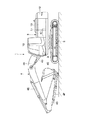
まず、図1ないし図8は、本発明の第1の実施の形態を示している。図1において、油圧ショベル1は、土砂の掘削作業等に用いられる建設機械である。この油圧ショベル1は、自走可能なクローラ式の下部走行体2と、該下部走行体2に旋回可能に搭載された上部旋回体3と、該上部旋回体3の前側に俯仰動可能に設けられた作業装置4とにより大略構成されている。   First, FIG. 1 to FIG. 8 show a first embodiment of the present invention. In FIG. 1, a hydraulic excavator 1 is a construction machine used for excavation work of earth and sand. The hydraulic excavator 1 includes a self-propelled crawler-type lower traveling body 2, an upper revolving body 3 that is turnably mounted on the lower traveling body 2, and an upside-down movable structure provided on the front side of the upper revolving body 3. The working device 4 is generally configured.

ここで、下部走行体2には走行モータ(図示せず)が設けられると共に、上部旋回体3には旋回モータ(図示せず)が設けられている。下部走行体2は走行モータによって前進、後進等の走行動作を行い、上部旋回体3は旋回モータによって旋回動作するものである。   Here, the lower traveling body 2 is provided with a traveling motor (not shown), and the upper turning body 3 is provided with a turning motor (not shown). The lower traveling body 2 performs traveling operations such as advancing and reversing by a traveling motor, and the upper swing body 3 is rotated by a swing motor.

作業装置4は、ブーム4A、アーム4B、バケット4Cによって構成され、ブーム4A、アーム4B、バケット4Cには、ブームシリンダ4D、アームシリンダ4E、バケットシリンダ4Fが取付けられている。これらのシリンダ4D,4E,4Fは、走行モータ、旋回モータと共に、後述の油圧ポンプ14から吐出する圧油により駆動される油圧アクチュエータを構成するものである。   The work device 4 includes a boom 4A, an arm 4B, and a bucket 4C. A boom cylinder 4D, an arm cylinder 4E, and a bucket cylinder 4F are attached to the boom 4A, the arm 4B, and the bucket 4C. These cylinders 4D, 4E, and 4F constitute a hydraulic actuator that is driven by pressure oil discharged from a hydraulic pump 14, which will be described later, together with a traveling motor and a turning motor.

各シリンダ4D,4E,4Fは、チューブ5内がピストン6により2つの油室7A,7Bに画成され、基端側がピストン6に固着されたロッド8は、その先端側がチューブ5外に突出している。   Each cylinder 4D, 4E, 4F has a tube 5 defined by a piston 6 into two oil chambers 7A, 7B, and a rod 8 whose proximal end is fixed to the piston 6 has its distal end protruding outside the tube 5. Yes.

旋回フレーム9は、上部旋回体3の支持構造体を形成する支持フレームであり、下部走行体2上に旋回可能に搭載されている。旋回フレーム9には、後述のキャブ10、カウンタウエイト12、油圧ポンプ14、コントロールバルブ17等が搭載されている。   The turning frame 9 is a support frame that forms a support structure for the upper turning body 3, and is mounted on the lower traveling body 2 so as to be turnable. A cab 10, a counterweight 12, a hydraulic pump 14, a control valve 17 and the like, which will be described later, are mounted on the revolving frame 9.

キャブ10は、作業装置4を挟んで左,右方向の左側に位置して、旋回フレーム9上に設けられている。このキャブ10は、オペレータが搭乗するもので、その内部には、オペレータが着座する運転席、作業装置4を操作する操作レバー11A(図2参照)、走行レバー、空調装置(いずれも図示せず)等が配設されている。一方、旋回フレーム9の後端部には、作業装置4との重量バランスをとるカウンタウエイト12が設けられている。   The cab 10 is provided on the revolving frame 9 so as to be positioned on the left side in the left and right directions with the work device 4 interposed therebetween. The cab 10 is carried by an operator. Inside the cab 10 is a driver's seat on which the operator is seated, an operation lever 11A (see FIG. 2) for operating the work device 4, a travel lever, and an air conditioner (not shown). ) Etc. are arranged. On the other hand, a counterweight 12 is provided at the rear end of the revolving frame 9 to balance the weight with the work device 4.

機械室13は、キャブ10とカウンタウエイト12との間に形成されている。この機械室13には、図示しないエンジン、油圧ポンプ14、パイロットポンプ16、コントロールバルブ17、その他機器等が配設されている。   The machine room 13 is formed between the cab 10 and the counterweight 12. The machine room 13 is provided with an engine, a hydraulic pump 14, a pilot pump 16, a control valve 17, and other devices not shown.

油圧ポンプ14は、エンジンによって駆動されることにより、作動油タンク15に貯えられた作動油をブームシリンダ4D等の油圧アクチュエータに向けて圧油として吐出するものである。パイロットポンプ16は、油圧ポンプ14と共にエンジンによって駆動され、作動油タンク15に貯えられた作動油を操作レバー11Aを有するパイロット弁11に向けて圧油として吐出するものである。   The hydraulic pump 14 is driven by the engine to discharge the hydraulic oil stored in the hydraulic oil tank 15 as hydraulic oil toward a hydraulic actuator such as the boom cylinder 4D. The pilot pump 16 is driven by the engine together with the hydraulic pump 14 and discharges hydraulic oil stored in the hydraulic oil tank 15 as pressure oil toward the pilot valve 11 having the operation lever 11A.

コントロールバルブ17は、作動油タンク15、油圧ポンプ14と各油圧アクチュエータ(シリンダ4D〜4F等)との間に設けられている。このコントロールバルブ17は、例えば操作レバー11Aに対する操作に応じて、シリンダ4D〜4Fに対する圧油の給排、停止を制御するものである。そして、コントロールバルブ17には、油圧アクチュエータごとに後述のスプール弁装置21が設けられている。   The control valve 17 is provided between the hydraulic oil tank 15, the hydraulic pump 14, and each hydraulic actuator (cylinders 4D to 4F, etc.). The control valve 17 controls supply / discharge and stop of the pressure oil to the cylinders 4D to 4F, for example, according to an operation on the operation lever 11A. The control valve 17 is provided with a spool valve device 21 described later for each hydraulic actuator.

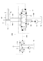
ここで、油圧アクチュエータ(ブームシリンダ4D)駆動用の油圧回路について、図2を参照して説明する。   Here, a hydraulic circuit for driving the hydraulic actuator (boom cylinder 4D) will be described with reference to FIG.

コントロールバルブ17は、ポンプ管路18A、タンク管路18Bにより油圧ポンプ14と作動油タンク15とに接続されている。また、スプール弁装置21が中立位置(I)にあるときに、ポンプ管路18Aとタンク管路18Bとは、バイパス管路18Cで接続されている。ポンプ管路18A、タンク管路18B、バイパス管路18Cは、例えば金属配管および可撓性ホース等を含んだ油圧管路により構成されている。   The control valve 17 is connected to the hydraulic pump 14 and the hydraulic oil tank 15 by a pump line 18A and a tank line 18B. When the spool valve device 21 is in the neutral position (I), the pump line 18A and the tank line 18B are connected by a bypass line 18C. The pump line 18A, the tank line 18B, and the bypass line 18C are configured by hydraulic lines including, for example, a metal pipe and a flexible hose.

ポンプ管路18Aの途中部位には、油圧ポンプ14が設けられている。ポンプ管路18Aは、油圧ポンプ14の駆動により作動油タンク15内の作動油をコントロールバルブ17内のスプール弁装置21へと導く。一方、タンク管路18Bは、スプール弁装置21から流出した作動油を作動油タンク15へと導くものである。バイパス管路18Cは、スプール30が中立位置にあるときに、ポンプ管路18Aからタンク管路18Bに作動油を導くものである。なお、図3、図6、図7では、バイパス管路18Cを省略している。   A hydraulic pump 14 is provided in the middle of the pump line 18A. The pump line 18 </ b> A guides the hydraulic oil in the hydraulic oil tank 15 to the spool valve device 21 in the control valve 17 by driving the hydraulic pump 14. On the other hand, the tank line 18 </ b> B guides the hydraulic oil flowing out from the spool valve device 21 to the hydraulic oil tank 15. The bypass line 18C guides hydraulic oil from the pump line 18A to the tank line 18B when the spool 30 is in the neutral position. 3, 6, and 7, the bypass conduit 18 </ b> C is omitted.

また、コントロールバルブ17は、主管路19A,19Bによりブームシリンダ4Dと接続されている。主管路19A,19Bは、例えば金属配管および可撓性ホース等を含んだ油圧管路により構成されている。主管路19Aは、ブームシリンダ4Dの油室7Aに接続され、主管路19Bは、ブームシリンダ4Dの油室7Bに接続されている。そして、油圧ポンプ14からの圧油は、スプール弁装置21を介して主管路19A,19Bからブームシリンダ4Dに給排される。これにより、ブームシリンダ4Dのロッド8は、チューブ5から伸縮動作する。   Further, the control valve 17 is connected to the boom cylinder 4D through main pipelines 19A and 19B. The main pipelines 19A and 19B are constituted by hydraulic pipelines including, for example, metal pipes and flexible hoses. The main pipeline 19A is connected to the oil chamber 7A of the boom cylinder 4D, and the main pipeline 19B is connected to the oil chamber 7B of the boom cylinder 4D. Then, the pressure oil from the hydraulic pump 14 is supplied and discharged from the main pipelines 19A and 19B to the boom cylinder 4D via the spool valve device 21. Thereby, the rod 8 of the boom cylinder 4 </ b> D expands and contracts from the tube 5.

操作レバー11Aとコントロールバルブ17とは、パイロット管路20A,20Bにより接続されている。パイロット管路20Aは、スプール弁装置21の左パイロット油室35Aに接続され、パイロット管路20Bは、スプール弁装置21の右パイロット油室35Bに接続されている。そして、オペレータが操作レバー11Aを中立位置から作動位置に傾転操作したときには、その操作量に対応したパイロット圧がパイロット管路20A,20Bを介してスプール弁装置21の左,右のパイロット油室35A,35Bへと給排される。これにより、スプール弁装置21のスプール30は、中立位置(I)から作動位置(II)または(III)に切換わる(図2参照)。   The operation lever 11A and the control valve 17 are connected by pilot pipelines 20A and 20B. The pilot pipe line 20A is connected to the left pilot oil chamber 35A of the spool valve device 21, and the pilot pipe line 20B is connected to the right pilot oil chamber 35B of the spool valve device 21. When the operator tilts the operation lever 11A from the neutral position to the operating position, the pilot pressure corresponding to the operation amount is supplied to the left and right pilot oil chambers of the spool valve device 21 via the pilot pipe lines 20A and 20B. Supplyed and discharged to 35A and 35B. Thereby, the spool 30 of the spool valve device 21 is switched from the neutral position (I) to the operating position (II) or (III) (see FIG. 2).

次に、コントロールバルブ17内に設けられたスプール弁装置21について説明する。   Next, the spool valve device 21 provided in the control valve 17 will be described.

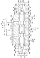
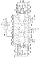
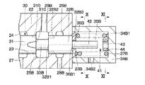
スプール弁装置21は、油圧ポンプ14、作動油タンク15とブームシリンダ4Dとの間に設けられたものである。このスプール弁装置21は、スプール30を図3に示す中立位置から例えば図6、図7に示す切換位置に摺動変位させることにより、ブームシリンダ4Dに給排する圧油の方向および流量を制御する方向制御弁として構成されたものである。スプール弁装置21は、後述のポンプポート27を境にしてスプール30の軸方向で対称に形成されている。そして、スプール弁装置21は、ハウジング22、スプール30、左,右のキャップ34A,34B、左,右のスプリング37A,37B等を含んで構成されている。   The spool valve device 21 is provided between the hydraulic pump 14, the hydraulic oil tank 15, and the boom cylinder 4D. The spool valve device 21 controls the direction and flow rate of pressure oil supplied to and discharged from the boom cylinder 4D by sliding the spool 30 from the neutral position shown in FIG. 3 to the switching position shown in FIGS. 6 and 7, for example. It is configured as a directional control valve. The spool valve device 21 is formed symmetrically in the axial direction of the spool 30 with a pump port 27 described later as a boundary. The spool valve device 21 includes a housing 22, a spool 30, left and right caps 34A and 34B, left and right springs 37A and 37B, and the like.

ハウジング22は、スプール弁装置21の弁本体を構成するものである。図3に示すように、ハウジング22の内周側には、左,右方向に延びたスプール摺動穴23が設けられている。スプール摺動穴23の左端部23Aには、後述の左キャップ34Aが設けられ、スプール摺動穴23の右端部23Bには、後述の右キャップ34Bが設けられている。   The housing 22 constitutes a valve body of the spool valve device 21. As shown in FIG. 3, a spool sliding hole 23 extending in the left and right directions is provided on the inner peripheral side of the housing 22. A left cap 34A described later is provided at the left end 23A of the spool sliding hole 23, and a right cap 34B described later is provided at the right end 23B of the spool sliding hole 23.

スプール摺動穴23の軸方向の中央部には、環状の中央油溝24が形成されている。また、中央油溝24の左,右両側には、環状の左側油溝25A,右側油溝25Bが形成されている。さらに、左側油溝25Aよりも左端側には、環状の左端側油溝26Aが形成され、右側油溝25Bよりも右端側には、環状の右端側油溝26Bが形成されている。   An annular central oil groove 24 is formed in the axial center of the spool sliding hole 23. An annular left oil groove 25 </ b> A and right oil groove 25 </ b> B are formed on both the left and right sides of the central oil groove 24. Furthermore, an annular left end side oil groove 26A is formed on the left end side of the left oil groove 25A, and an annular right end side oil groove 26B is formed on the right end side of the right oil groove 25B.

また、ハウジング22には、スプール摺動穴23の軸方向にそれぞれ離間してポンプポート27、左,右のタンクポート28A,28B、および左,右のアクチュエータポート29A,29Bが設けられている。ポンプポート27は、一側がポンプ管路18Aに接続され、他側が中央油溝24に連通している。   The housing 22 is provided with a pump port 27, left and right tank ports 28A and 28B, and left and right actuator ports 29A and 29B, which are spaced apart from each other in the axial direction of the spool sliding hole 23. One side of the pump port 27 is connected to the pump line 18 </ b> A, and the other side communicates with the central oil groove 24.

左タンクポート28Aは、一側がタンク管路18Bに接続され、他側が左端側油溝26Aに連通している。一方、右タンクポート28Bは、一側がタンク管路18Bに接続され、他側が右端側油溝26Bに連通している。   The left tank port 28A has one side connected to the tank pipeline 18B and the other side communicating with the left end side oil groove 26A. On the other hand, the right tank port 28B has one side connected to the tank pipeline 18B and the other side communicating with the right end side oil groove 26B.

左アクチュエータポート29Aは、一側が左側油溝25Aに連通し、他側が主管路19Aに接続されている。一方、右アクチュエータポート29Bは、一側が右側油溝25Bに連通し、他側が主管路19Bに接続されている。   The left actuator port 29A has one side communicating with the left oil groove 25A and the other side connected to the main pipeline 19A. On the other hand, the right actuator port 29B has one side communicating with the right oil groove 25B and the other side connected to the main pipeline 19B.

スプール30は、ハウジング22のスプール摺動穴23に摺動可能に挿嵌されている。このスプール30は、後述の左,右のパイロット油室35A,35Bに供給されるパイロット圧に従ってスプール摺動穴23内を左,右方向に摺動変位するものである。スプール30の軸方向中間部には、ランドとしての中央ランド31が設けられている。また、スプール30の軸方向両端側には、ランドとしての左側ランド32A、右側ランド32Bが設けられている。これら各ランド31,32A,32Bは、スプール摺動穴23に対して軸方向および回転方向に摺動する。   The spool 30 is slidably inserted into the spool sliding hole 23 of the housing 22. The spool 30 is slidably displaced in the left and right directions in the spool sliding hole 23 in accordance with a pilot pressure supplied to left and right pilot oil chambers 35A and 35B described later. A central land 31 as a land is provided at an intermediate portion in the axial direction of the spool 30. Further, a left land 32 </ b> A and a right land 32 </ b> B as lands are provided at both axial ends of the spool 30. Each of the lands 31, 32 A, 32 B slides in the axial direction and the rotational direction with respect to the spool sliding hole 23.

中央ランド31の左端部31A側には、軸方向に延びるノッチ31Bが周方向に離間して複数個形成され、右端部31C側には軸方向に延びるノッチ31Dが周方向に離間して複数個形成されている。ノッチ31Bは、中央油溝24と左側油溝25Aとの間、即ちポンプポート27と左アクチュエータポート29Aとの間を流れる圧油を小流量で連通させるものである。一方、ノッチ31Dは、中央油溝24と右側油溝25Bとの間、即ちポンプポート27と右アクチュエータポート29Bとの間を流れる圧油を小流量で連通させるものである。   A plurality of notches 31B extending in the axial direction are formed on the left end portion 31A side of the central land 31 and spaced apart in the circumferential direction, and a plurality of notches 31D extending in the axial direction are spaced apart on the right end portion 31C side. Is formed. The notch 31B communicates the pressure oil flowing between the central oil groove 24 and the left oil groove 25A, that is, between the pump port 27 and the left actuator port 29A, with a small flow rate. On the other hand, the notch 31D communicates the pressure oil flowing between the central oil groove 24 and the right oil groove 25B, that is, between the pump port 27 and the right actuator port 29B, with a small flow rate.

左側ランド32Aの右端部32A1側には、軸方向に延びるノッチ32A2が周方向に離間して複数個形成されている。ノッチ32A2は、左側油溝25Aと左端側油溝26Aとの間、即ち左アクチュエータポート29Aと左タンクポート28Aとの間を流れる圧油を小流量で連通させるものである。また、左側ランド32Aの左端部32A3側、即ちスプール30の左端部には、後述の左突出軸部39Aが設けられている。   On the right end 32A1 side of the left land 32A, a plurality of notches 32A2 extending in the axial direction are formed apart from each other in the circumferential direction. The notch 32A2 communicates the pressure oil flowing between the left oil groove 25A and the left end oil groove 26A, that is, between the left actuator port 29A and the left tank port 28A, with a small flow rate. Further, a left protruding shaft portion 39A described later is provided on the left end portion 32A3 side of the left land 32A, that is, on the left end portion of the spool 30.

一方、右側ランド32Bの左端部32B1側には、軸方向に延びるノッチ32B2が周方向に離間して複数個形成されている。ノッチ32B2は、右側油溝25Bと右端側油溝26Bとの間、即ち右アクチュエータポート29Bと右タンクポート28Bとの間を流れる圧油を小流量で連通させるものである。また、右側ランド32Bの右端部32B3側、即ちスプール30の右端部には、後述の右突出軸部39Bが設けられている。   On the other hand, on the left end 32B1 side of the right land 32B, a plurality of notches 32B2 extending in the axial direction are formed apart from each other in the circumferential direction. The notch 32B2 communicates the pressure oil flowing between the right oil groove 25B and the right end oil groove 26B, that is, between the right actuator port 29B and the right tank port 28B, with a small flow rate. Further, a right protruding shaft portion 39B described later is provided on the right end portion 32B3 side of the right land 32B, that is, on the right end portion of the spool 30.

中央ランド31と左側ランド32Aとの間は、各ランド31,32A,32Bの外径寸法よりも小さい外径寸法を有する左軸部33Aで接続されている。また、中央ランド31と右側ランド32Bとの間は、各ランド31,32A,32Bの外径寸法よりも小さい外径寸法を有する右軸部33Bで接続されている。   The center land 31 and the left land 32A are connected by a left shaft portion 33A having an outer diameter smaller than the outer diameter of each land 31, 32A, 32B. Further, the center land 31 and the right land 32B are connected by a right shaft portion 33B having an outer diameter smaller than the outer diameter of each land 31, 32A, 32B.

図3に示すように、スプール30が中立位置にあるときには、中央ランド31が中央油溝24と左側油溝25A、右側油溝25Bとの間を遮断する。この場合、油圧ポンプ14から吐出された圧油は、ポンプ管路18Aからバイパス管路18Cを介してタンク管路18Bへと導かれ作動油タンク15に戻される。   As shown in FIG. 3, when the spool 30 is in the neutral position, the center land 31 blocks between the center oil groove 24, the left oil groove 25A, and the right oil groove 25B. In this case, the pressure oil discharged from the hydraulic pump 14 is guided from the pump line 18A to the tank line 18B via the bypass line 18C and returned to the hydraulic oil tank 15.

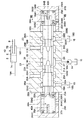
一方、図6、図7に示すように、例えばスプール30が中立位置から右方向に変位したときには、中央ランド31により中央油溝24と左側油溝25Aとの間が連通され、右側ランド32Bにより右側油溝25Bと右端側油溝26Bとの間が連通される。この場合、油圧ポンプ14から吐出された圧油は、ポンプポート27から左アクチュエータポート29Aへと導かれ、主管路19Aを介してブームシリンダ4Dの油室7Aに供給される。これにより、ブームシリンダ4Dのロッド8を伸長させることができる。また、油室7Bから主管路19Bに戻された圧油は、右アクチュエータポート29Bから右側ランド32Bを介して右タンクポート28Bへと導かれ、タンク管路18Bを介して作動油タンク15に戻される。   On the other hand, as shown in FIGS. 6 and 7, for example, when the spool 30 is displaced rightward from the neutral position, the central land 31 communicates between the central oil groove 24 and the left oil groove 25A, and the right land 32B. The right oil groove 25B and the right end oil groove 26B communicate with each other. In this case, the pressure oil discharged from the hydraulic pump 14 is guided from the pump port 27 to the left actuator port 29A, and is supplied to the oil chamber 7A of the boom cylinder 4D via the main pipeline 19A. Thereby, the rod 8 of the boom cylinder 4D can be extended. The pressure oil returned from the oil chamber 7B to the main pipeline 19B is guided from the right actuator port 29B to the right tank port 28B via the right land 32B, and returned to the hydraulic oil tank 15 via the tank pipeline 18B. It is.

左キャップ34Aは、スプール摺動穴23の軸方向の左端部23Aに位置してハウジング22に設けられている。一方、右キャップ34Bは、スプール摺動穴23の軸方向の右端部23Bに位置してハウジング22に設けられている。これらキャップ34A,34Bは、同じ構成からなり左,右方向で対称形状となっている。以下、図3、図4を参照して右キャップ34Bについて説明し、左キャップ34Aについては説明を省略する。   The left cap 34 </ b> A is provided in the housing 22 at the left end 23 </ b> A in the axial direction of the spool sliding hole 23. On the other hand, the right cap 34 </ b> B is provided in the housing 22 at the right end 23 </ b> B in the axial direction of the spool sliding hole 23. The caps 34A and 34B have the same configuration and are symmetrical in the left and right directions. Hereinafter, the right cap 34B will be described with reference to FIGS. 3 and 4, and description of the left cap 34A will be omitted.

右キャップ34Bは、底部34B1を有する有底筒状に形成され、スプール摺動穴23の右端部23Bを閉塞するものである。また、右キャップ34Bには、パイロット管路20Bの接続ポート34B2が設けられている。そして、右キャップ34Bの内部には、スプール30を軸方向に摺動変位させるための右パイロット油室35Bが形成されている。   The right cap 34B is formed in a bottomed cylindrical shape having a bottom portion 34B1 and closes the right end portion 23B of the spool sliding hole 23. The right cap 34B is provided with a connection port 34B2 for the pilot pipeline 20B. A right pilot oil chamber 35B for slidingly displacing the spool 30 in the axial direction is formed in the right cap 34B.

この右キャップ34Bの内径は、スプール摺動穴23の孔径よりも大きく形成されている。そして、右パイロット油室35Bは、接続ポート34B2を介してパイロット管路20Bに接続され、油圧ショベル1のオペレータが手動操作する操作レバー11Aのパイロット弁11からパイロット圧が供給される。そして、スプール30は、このときのパイロット圧に従ってスプール摺動穴23内を左,右方向に摺動変位する。   The inner diameter of the right cap 34 </ b> B is formed larger than the diameter of the spool sliding hole 23. The right pilot oil chamber 35B is connected to the pilot pipe line 20B via the connection port 34B2, and pilot pressure is supplied from the pilot valve 11 of the operation lever 11A that is manually operated by the operator of the excavator 1. The spool 30 is slidably displaced in the left and right directions in the spool sliding hole 23 according to the pilot pressure at this time.

同様に、左キャップ34Aには、底部34A1、接続ポート34A2が設けられている。そして、左キャップ34Aの内部には、左パイロット油室35Aが形成されている。この左パイロット油室35Aは、接続ポート34A2を介してパイロット管路20Aに接続されている。   Similarly, the left cap 34A is provided with a bottom 34A1 and a connection port 34A2. A left pilot oil chamber 35A is formed inside the left cap 34A. The left pilot oil chamber 35A is connected to the pilot pipeline 20A via a connection port 34A2.

左ばね受36Aは、左側ランド32Aの左端部32A3に当接した状態で左パイロット油室35A内に配設されている。この左ばね受36Aは、例えば耐摩耗性、潤滑性を有する樹脂材料からなり、その外径寸法は、左キャップ34Aの内径とほぼ同じ寸法となっている。また、左ばね受36Aには、軸方向に貫通する貫通孔36A1が形成されている。この貫通孔36A1には、後述する左突出軸部39Aが挿通される。左ばね受36Aは、後述の左スプリング37Aを支持すると共に、本発明の摺動部材を構成するもので、スプール30の左端部32A3と左スプリング37Aとの相対回転を許すものである。   The left spring receiver 36A is disposed in the left pilot oil chamber 35A in a state where it abuts on the left end portion 32A3 of the left land 32A. The left spring receiver 36A is made of, for example, a resin material having wear resistance and lubricity, and the outer diameter thereof is substantially the same as the inner diameter of the left cap 34A. Further, the left spring bearing 36A is formed with a through hole 36A1 penetrating in the axial direction. A left protruding shaft portion 39A, which will be described later, is inserted through the through hole 36A1. The left spring support 36A supports a later-described left spring 37A and constitutes a sliding member of the present invention, and allows relative rotation between the left end portion 32A3 of the spool 30 and the left spring 37A.

同様に、右ばね受36Bは、右側ランド32Bの右端部32B3に当接した状態で右パイロット油室35B内に配設されている。この右ばね受36Bは、例えば耐摩耗性、潤滑性を有する樹脂材料からなり、その外径寸法は、右キャップ34Bの内径とほぼ同じ寸法となっている。また、右ばね受36Bには、軸方向に貫通する貫通孔36B1が形成されている。この貫通孔36B1には、後述する右突出軸部39Bが挿通される。右ばね受36Bは、後述の右スプリング37Bを支持すると共に、本発明の摺動部材を構成するもので、スプール30の右端部32B3と後述の右スプリング37Bとの相対回転を許すものである。なお、これら左ばね受36A、右ばね受36Bは、1枚に限らず複数枚に重ねて用いてもよい。   Similarly, the right spring receiver 36B is disposed in the right pilot oil chamber 35B in a state of being in contact with the right end portion 32B3 of the right land 32B. The right spring receiver 36B is made of, for example, a resin material having wear resistance and lubricity, and the outer diameter thereof is substantially the same as the inner diameter of the right cap 34B. Further, a through hole 36B1 penetrating in the axial direction is formed in the right spring receiver 36B. A right protruding shaft portion 39B, which will be described later, is inserted through the through hole 36B1. The right spring support 36B supports a later-described right spring 37B and constitutes a sliding member of the present invention, and allows relative rotation between a right end portion 32B3 of the spool 30 and a later-described right spring 37B. The left spring receiver 36A and the right spring receiver 36B are not limited to a single sheet, and may be used in a stacked manner.

左スプリング37Aは、左キャップ34A内に配設されたものである。この左スプリング37Aは、後述する左突出軸部39Aの外周側で左キャップ34Aの底部34A1と左ばね受36Aとの間に設けられている。そして、左スプリング37Aは、左ばね受36Aを介してスプール30を中立位置に向けて付勢している。即ち、左スプリング37Aは、スプール30を中立位置に戻すためのセンタリング用のばね部材である。右キャップ34Bの接続ポート34B2から右パイロット油室35Bに圧油(パイロット圧)が供給されてスプール30が左方向に摺動変位するときに、左スプリング37Aは、スプール30の左端部32A3から左ばね受36Aを介して左方向に押圧されて圧縮変形される。   The left spring 37A is disposed in the left cap 34A. The left spring 37A is provided between the bottom 34A1 of the left cap 34A and the left spring support 36A on the outer peripheral side of the left protruding shaft portion 39A described later. The left spring 37A biases the spool 30 toward the neutral position via the left spring receiver 36A. That is, the left spring 37A is a centering spring member for returning the spool 30 to the neutral position. When pressure oil (pilot pressure) is supplied from the connection port 34B2 of the right cap 34B to the right pilot oil chamber 35B and the spool 30 is slid in the left direction, the left spring 37A is moved to the left from the left end portion 32A3 of the spool 30. It is compressed and deformed by being pressed leftward through the spring support 36A.

同様に、右スプリング37Bは、右キャップ34B内に配設されたものである。この右スプリング37Bは、後述する右突出軸部39Bの外周側で右キャップ34Bの底部34B1と右ばね受36Bとの間に設けられている。右スプリング37Bは、右ばね受36Bを介してスプール30を中立位置に向けて付勢している。即ち、右スプリング37Bは、スプール30を中立位置に戻すためのセンタリング用のばね部材である。左キャップ34Aの接続ポート34A2から左パイロット油室35Aに圧油(パイロット圧)が供給されてスプール30が右方向に摺動変位するときに、右スプリング37Bは、スプール30の右端部32B3から右ばね受36Bを介して右方向に押圧されて圧縮変形される。   Similarly, the right spring 37B is disposed in the right cap 34B. The right spring 37B is provided between the bottom 34B1 of the right cap 34B and the right spring receiver 36B on the outer peripheral side of a right protruding shaft portion 39B described later. The right spring 37B biases the spool 30 toward the neutral position via the right spring receiver 36B. That is, the right spring 37B is a centering spring member for returning the spool 30 to the neutral position. When pressure oil (pilot pressure) is supplied from the connection port 34A2 of the left cap 34A to the left pilot oil chamber 35A and the spool 30 is slid to the right, the right spring 37B is moved from the right end 32B3 of the spool 30 to the right. It is compressed and deformed by being pressed to the right via the spring support 36B.

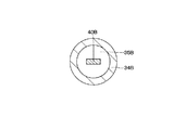
次に、本発明の回転規制部38Aおよび回転規制部38Bについて説明する。なお、回転規制部38Aと回転規制部38Bとは、同じ構成からなり左,右方向で対称形状となっている。以下、図3、図4を参照して回転規制部38Bについて説明し、回転規制部38Aについてはその説明を省略する。   Next, the rotation restricting portion 38A and the rotation restricting portion 38B of the present invention will be described. The rotation restricting portion 38A and the rotation restricting portion 38B have the same configuration and are symmetrical in the left and right directions. Hereinafter, the rotation restricting portion 38B will be described with reference to FIGS. 3 and 4, and the description of the rotation restricting portion 38A will be omitted.

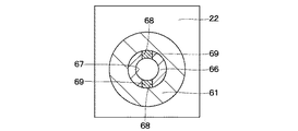
回転規制部38Bは、スプール30の右端部32B3と右キャップ34Bとの間に設けられている。この回転規制部38Bは、スプール30が右キャップ34B内に向けて変位したときに、スプール30のスプール摺動穴23内における回転を規制するものである。また、回転規制部38Bは、スプール30の回転が規制されるまでは、スプール30のスプール摺動穴23内における回転を許容するものである。そして、回転規制部38Bは、右突出軸部39Bと、右嵌合突部40Bとにより構成されている。   The rotation restricting portion 38B is provided between the right end portion 32B3 of the spool 30 and the right cap 34B. The rotation restricting portion 38B restricts the rotation of the spool 30 in the spool sliding hole 23 when the spool 30 is displaced toward the right cap 34B. Further, the rotation restricting portion 38B allows the rotation of the spool 30 in the spool sliding hole 23 until the rotation of the spool 30 is restricted. And the rotation control part 38B is comprised by the right protrusion axial part 39B and the right fitting protrusion 40B.

右突出軸部39Bは、スプール30の右端部32B3に設けられ、右キャップ34B内に向けて軸方向に突出するものである。この右突出軸部39Bは、円柱体からなり右側ランド32Bに一体形成され、右ばね受36Bの貫通孔36B1を挿通している。右突出軸部39Bの右端側には、径方向に貫通するキー溝39B1が形成されている。   The right protruding shaft portion 39B is provided at the right end portion 32B3 of the spool 30 and protrudes in the axial direction toward the right cap 34B. The right protruding shaft portion 39B is formed of a cylindrical body, is integrally formed with the right land 32B, and is inserted through the through hole 36B1 of the right spring support 36B. A key groove 39B1 penetrating in the radial direction is formed on the right end side of the right protruding shaft portion 39B.

また、右突出軸部39Bの右面は、キー溝39B1に向けて徐々に縮径するテーパ面39B2となっている。このテーパ面39B2は、後述の嵌合部としての右嵌合突部40Bをキー溝39B1へと案内するものである。キー溝39B1の深さ寸法およびテーパ面39B2の深さ寸法は、後述の右嵌合突部40Bの長さ寸法と共に、スプール30の回転を規制し始める位置およびスプール30のストロークエンドとの関係により適宜設定される。この場合、右突出軸部39Bは、スプール30の一部を構成するものである。   The right surface of the right protruding shaft portion 39B is a tapered surface 39B2 that gradually decreases in diameter toward the key groove 39B1. This taper surface 39B2 guides a right fitting protrusion 40B as a fitting portion described later to the key groove 39B1. The depth dimension of the key groove 39B1 and the depth dimension of the tapered surface 39B2 depend on the relationship between the position where the rotation of the spool 30 starts to be restricted and the stroke end of the spool 30 together with the length dimension of the right fitting protrusion 40B described later. Set as appropriate. In this case, the right protruding shaft portion 39 </ b> B constitutes a part of the spool 30.

右嵌合突部40Bは、右キャップ34Bの底部34B1側で右パイロット油室35B内に突出して設けられている。この右嵌合突部40Bは、右突出軸部39Bのキー溝39B1に対応して形成され、スプール30が右方向に変位したときに右突出軸部39Bのキー溝39B1が進退可能に嵌合するものである。   The right fitting protrusion 40B is provided to protrude into the right pilot oil chamber 35B on the bottom 34B1 side of the right cap 34B. The right fitting protrusion 40B is formed to correspond to the key groove 39B1 of the right protruding shaft portion 39B, and is fitted so that the key groove 39B1 of the right protruding shaft portion 39B can advance and retract when the spool 30 is displaced in the right direction. To do.

具体的には、図6に示すように、スプール30が右方向に所定量摺動変位したときに、右突出軸部39Bのキー溝39B1と右嵌合突部40Bとが嵌合することにより、スプール30の回転が規制される。そして、図7に示すように、スプール30の回転が規制された状態で、スプール30は、右突出軸部39Bのキー溝39B1の底部に右嵌合突部40Bが当接するまで(即ち、ストロークエンドまで)軸方向に移動可能となっている。   Specifically, as shown in FIG. 6, when the spool 30 is slid to the right by a predetermined amount, the key groove 39B1 of the right protruding shaft portion 39B and the right fitting protrusion 40B are engaged. The rotation of the spool 30 is restricted. As shown in FIG. 7, in the state where the rotation of the spool 30 is restricted, the spool 30 is moved until the right fitting protrusion 40B comes into contact with the bottom of the key groove 39B1 of the right protruding shaft part 39B (that is, the stroke It can move in the axial direction (to the end).

同様に、回転規制部38Aは、左突出軸部39Aと、左嵌合突部40Aとにより構成されている。そして、左突出軸部39Aには、キー溝39A1、テーパ面39A2が形成されている。   Similarly, the rotation restricting portion 38A includes a left protruding shaft portion 39A and a left fitting protruding portion 40A. A key groove 39A1 and a tapered surface 39A2 are formed in the left protruding shaft portion 39A.

本実施の形態によるブームシリンダ4D用のスプール弁装置21は、上述の如き構成を有するもので、次にその作動について説明する。   The spool valve device 21 for the boom cylinder 4D according to the present embodiment has the above-described configuration, and the operation thereof will be described next.

まず、スプール弁装置21の左側に設けられた左キャップ34A内の左パイロット油室35Aには、油圧ショベル1のオペレータが手動操作する操作レバー11Aのパイロット弁11からパイロット管路20A、接続ポート34A2を介してパイロット圧が供給される。一方、スプール弁装置21の右側に設けられた右キャップ34B内の右パイロット油室35Bには、油圧ショベル1のオペレータが手動操作する操作レバー11Aの減圧弁型パイロット弁11等からパイロット管路20B、接続ポート34B2を介してパイロット圧が供給される。   First, the left pilot oil chamber 35A in the left cap 34A provided on the left side of the spool valve device 21 is connected to the pilot valve 20A and the connection port 34A2 from the pilot valve 11 of the operation lever 11A manually operated by the operator of the hydraulic excavator 1. Pilot pressure is supplied via On the other hand, in the right pilot oil chamber 35B in the right cap 34B provided on the right side of the spool valve device 21, a pilot pipe line 20B is connected from the pressure reducing valve type pilot valve 11 of the operation lever 11A manually operated by the operator of the hydraulic excavator 1. The pilot pressure is supplied through the connection port 34B2.

そして、このときのパイロット圧がタンク圧のレベルまで下がっているときには、スプール30が左,右のスプリング37A,37Bにより中立位置に戻された状態となる。この場合、ハウジング22内に設けられたポンプポート27と左,右のアクチュエータポート29A,29Bとの間は、スプール30の中央ランド31により遮断された状態となり、左,右のアクチュエータポート29A,29Bと左,右のタンクポート28A,28Bとの間は、それぞれ左側ランド32A,右側ランド32Bにより遮断された状態となる。   When the pilot pressure at this time is reduced to the tank pressure level, the spool 30 is returned to the neutral position by the left and right springs 37A and 37B. In this case, the pump port 27 provided in the housing 22 and the left and right actuator ports 29A and 29B are blocked by the center land 31 of the spool 30, and the left and right actuator ports 29A and 29B are blocked. And the left and right tank ports 28A and 28B are blocked by the left land 32A and the right land 32B, respectively.

これにより、ブームシリンダ4Dの油室7A,7Bは、油圧ポンプ14から遮断されると共に、作動油タンク15からも遮断され、ブームシリンダ4Dのロッド8は、チューブ5から伸縮することなく停止状態に保持される。   As a result, the oil chambers 7A and 7B of the boom cylinder 4D are shut off from the hydraulic pump 14 and also from the hydraulic oil tank 15, and the rod 8 of the boom cylinder 4D is brought into a stopped state without expanding and contracting from the tube 5. Retained.

次に、例えば油圧ショベル1のオペレータがブームシリンダ4Dを作動するために、操作レバー11Aを傾転操作して、左キャップ34Aの左パイロット油室35A内にパイロット圧を供給すると、図6、図7に示すように、スプール30が右キャップ34B内の右スプリング37Bに抗して右方向に摺動変位した状態となる。この場合、ハウジング22内に設けられたポンプポート27と左アクチュエータポート29Aとの間は、中央油溝24、中央ランド31のノッチ31B、左側油溝25Aを介して連通した状態となる。また、右アクチュエータポート29Bと右タンクポート28Bとの間は、右側油溝25B、右側ランド32Bのノッチ32B2、右端側油溝26Bを介して連通した状態となる。   Next, for example, when the operator of the hydraulic excavator 1 operates the tilt lever 11A to operate the boom cylinder 4D and supplies the pilot pressure into the left pilot oil chamber 35A of the left cap 34A, FIG. As shown in FIG. 7, the spool 30 is slid in the right direction against the right spring 37B in the right cap 34B. In this case, the pump port 27 provided in the housing 22 and the left actuator port 29A communicate with each other via the central oil groove 24, the notch 31B of the central land 31 and the left oil groove 25A. Further, the right actuator port 29B and the right tank port 28B communicate with each other via the right oil groove 25B, the notch 32B2 of the right land 32B, and the right end oil groove 26B.

これにより、ブームシリンダ4Dの油室7Aには、油圧ポンプ14からの圧油がポンプ管路18A、ポンプポート27、中央油溝24、ノッチ31B、左側油溝25A、左アクチュエータポート29A、主管路19Aを介して供給される。また、ブームシリンダ4Dの油室7Bからの戻り油は、主管路19B、右アクチュエータポート29B、右側油溝25B、ノッチ32B2、右端側油溝26B、右タンクポート28Bを介してタンク管路18Bから作動油タンク15内に排出される。この結果、ブームシリンダ4Dのロッド8は、伸長方向に駆動される。   Thereby, in the oil chamber 7A of the boom cylinder 4D, the pressure oil from the hydraulic pump 14 is supplied to the pump line 18A, the pump port 27, the central oil groove 24, the notch 31B, the left oil groove 25A, the left actuator port 29A, and the main line. It is supplied via 19A. The return oil from the oil chamber 7B of the boom cylinder 4D is supplied from the tank pipe line 18B through the main pipe line 19B, the right actuator port 29B, the right oil groove 25B, the notch 32B2, the right end side oil groove 26B, and the right tank port 28B. The oil is discharged into the hydraulic oil tank 15. As a result, the rod 8 of the boom cylinder 4D is driven in the extending direction.

一方、オペレータが操作レバー11Aを中立位置から逆向きに傾転操作して、右キャップ34Bの右パイロット油室35B内にパイロット圧を供給すると、スプール30が左キャップ34A内の左スプリング37Aに抗して左方向に摺動変位した状態となる。この場合、ハウジング22内に設けられたポンプポート27と右アクチュエータポート29Bとの間は、中央油溝24、中央ランド31のノッチ31D、右側油溝25Bを介して連通した状態となる。また、左アクチュエータポート29Aと左タンクポート28Aとの間は、左側油溝25A、左側ランド32Aのノッチ32A2、左端側油溝26Aを介して連通した状態となる。   On the other hand, when the operator tilts the operation lever 11A in the reverse direction from the neutral position and supplies pilot pressure into the right pilot oil chamber 35B of the right cap 34B, the spool 30 resists the left spring 37A in the left cap 34A. Then, it is in a state of sliding displacement in the left direction. In this case, the pump port 27 provided in the housing 22 and the right actuator port 29B communicate with each other via the central oil groove 24, the notch 31D of the central land 31, and the right oil groove 25B. Further, the left actuator port 29A and the left tank port 28A communicate with each other via the left oil groove 25A, the notch 32A2 of the left land 32A, and the left end oil groove 26A.

これにより、ブームシリンダ4Dの油室7Bには、油圧ポンプ14からの圧油がポンプ管路18A、ポンプポート27、中央油溝24、ノッチ31D、右側油溝25B、右アクチュエータポート29B、主管路19Bを介して供給される。また、ブームシリンダ4Dの油室7Aからの戻り油は、主管路19A、左アクチュエータポート29A、左側油溝25A、ノッチ32A2、左端側油溝26A、左タンクポート28Aを介してタンク管路18Bから作動油タンク15内に排出される。この結果、ブームシリンダ4Dのロッド8は、縮小方向に駆動される。   Thereby, in the oil chamber 7B of the boom cylinder 4D, the pressure oil from the hydraulic pump 14 is supplied to the pump line 18A, the pump port 27, the central oil groove 24, the notch 31D, the right oil groove 25B, the right actuator port 29B, and the main line. It is supplied via 19B. The return oil from the oil chamber 7A of the boom cylinder 4D is supplied from the tank pipeline 18B via the main pipeline 19A, the left actuator port 29A, the left oil groove 25A, the notch 32A2, the left end side oil groove 26A, and the left tank port 28A. The oil is discharged into the hydraulic oil tank 15. As a result, the rod 8 of the boom cylinder 4D is driven in the reduction direction.

ところで、スプール弁装置21を圧油が通過するとき、ハウジング22のスプール摺動穴23に摺動可能に挿嵌されたスプール30は、作動油の粘性抵抗および動圧(流体力)によってスプール摺動穴23内で回転する。この場合、スプール30とハウジング22(スプール摺動穴23)との間で摩耗が生じ、スプール30およびハウジング22の寿命が低下してしまうという虞がある。   By the way, when pressure oil passes through the spool valve device 21, the spool 30 slidably inserted into the spool sliding hole 23 of the housing 22 is slid by the viscous resistance of the hydraulic oil and the dynamic pressure (fluid force). It rotates in the moving hole 23. In this case, wear may occur between the spool 30 and the housing 22 (spool sliding hole 23), and the life of the spool 30 and the housing 22 may be reduced.

そこで、上述の従来技術では、スプールの軸方向の端部にスプールの回転を規制する回転規制部を設けて、スプールの軸方向の摺動のみを可能とすることにより、スプールとハウジングとの間の摩耗を低減している。   Therefore, in the above-described prior art, a rotation restricting portion that restricts the rotation of the spool is provided at the end of the spool in the axial direction so that only the spool can slide in the axial direction. Reduces wear.

しかし、スプールのノッチを圧油が通過するときには、流速が急激に増加すると共に圧力が急激に低下し、作動油の圧力が飽和蒸気圧よりも低くなると、作動油中に気泡(所謂、キャビテーション)が発生する虞がある。液体中に発生した気泡は、流体噴流に乗って下流側へと導かれる。この気泡が押しつぶされて破裂した場合には、局所的に高い衝撃圧が発生し、この衝撃圧によりハウジングおよびスプールが浸食される虞がある。この場合、スプールの軸方向の摺動のみを可能としていると、気泡の破裂による衝撃圧は、同じ位置に集中して起こり、ハウジングおよびスプールの寿命が低下するという問題がある。   However, when the pressure oil passes through the notch of the spool, when the flow velocity increases rapidly and the pressure decreases rapidly, and the pressure of the hydraulic oil becomes lower than the saturated vapor pressure, bubbles (so-called cavitation) are generated in the hydraulic oil. May occur. Bubbles generated in the liquid are guided to the downstream side by riding on the fluid jet. When the bubbles are crushed and ruptured, a high impact pressure is locally generated, and the housing and the spool may be eroded by the impact pressure. In this case, when only the sliding of the spool in the axial direction is possible, the impact pressure due to the burst of bubbles occurs at the same position, and there is a problem that the life of the housing and the spool is reduced.

そこで、本実施の形態では、スプール30のストローク量が小さいときには、スプール30の回転を許容し、スプール30のストローク量が大きいときには、スプール30の回転を規制する構成としている。具体的には、スプール30が中立位置にある状態(図3の状態)から、例えばオペレータがブームシリンダ4Dを伸長側に作動するために、操作レバー11Aを傾転操作して、左キャップ34Aの左パイロット油室35A内にパイロット圧を供給すると、スプール30が右キャップ34B内の右スプリング37Bに抗して右方向に摺動変位する。   Therefore, in the present embodiment, the rotation of the spool 30 is allowed when the stroke amount of the spool 30 is small, and the rotation of the spool 30 is restricted when the stroke amount of the spool 30 is large. Specifically, from the state where the spool 30 is in the neutral position (the state shown in FIG. 3), for example, the operator tilts the operation lever 11A to operate the boom cylinder 4D to the extension side, and the left cap 34A When pilot pressure is supplied into the left pilot oil chamber 35A, the spool 30 slides and displaces in the right direction against the right spring 37B in the right cap 34B.

この場合、スプール30は、右突出軸部39Bのキー溝39B1と右嵌合突部40Bとが嵌合していないので回転可能となっている。スプール30が回転することにより、作動油の流れに変化を与えることができるので、例えばノッチ32B2で発生した気泡の破裂による衝撃圧を分散させることができる。これにより、ハウジング22の浸食を抑制することができる。   In this case, the spool 30 is rotatable because the key groove 39B1 of the right protruding shaft portion 39B and the right fitting protrusion 40B are not fitted. As the spool 30 rotates, it is possible to change the flow of the hydraulic oil, so that it is possible to disperse the impact pressure caused by, for example, bursting of bubbles generated in the notch 32B2. Thereby, erosion of the housing 22 can be suppressed.

オペレータが操作レバー11Aをさらに傾転操作すると、スプール30は、さらに右方向に摺動変位する。この場合、ポンプポート27と左アクチュエータポート29Aおよび右アクチュエータポート29Bと右タンクポート28Bとの間を通過する作動油の流量が多くなっていくので、スプール30の回転は徐々に増加する。そして、図6に示すように、右突出軸部39Bのキー溝39B1と右嵌合突部40Bとが嵌合すると、スプール30の回転が規制される。これにより、スプール30とハウジング22との間の摩耗を低減することができる。   When the operator further tilts the operation lever 11A, the spool 30 is further slid to the right. In this case, since the flow rate of the hydraulic fluid passing between the pump port 27 and the left actuator port 29A and between the right actuator port 29B and the right tank port 28B increases, the rotation of the spool 30 gradually increases. As shown in FIG. 6, when the key groove 39B1 of the right protruding shaft portion 39B and the right fitting protrusion 40B are fitted, the rotation of the spool 30 is restricted. Thereby, wear between the spool 30 and the housing 22 can be reduced.

さらに操作レバー11Aが傾転操作されると、スプール30は、回転規制部38B(右突出軸部39B、右嵌合突部40B)により回転が規制された状態で右方向に摺動変位し、図7に示すように、右突出軸部39Bのキー溝39B1の底部に右嵌合突部40Bが当接してスプール30のストロークエンドとなる。スプール30のストロークエンドの状態では、ポンプポート27と左アクチュエータポート29Aおよび右アクチュエータポート29Bと右タンクポート28Bとの間を通過する作動油の流量が多く、スプール30には強い回転力が働く。しかし、スプール30は、回転規制部38Bにより回転を規制されているので、スプール30とハウジング22との間の摩耗を低減することができる。   When the operation lever 11A is further tilted, the spool 30 is slid to the right in a state where the rotation is restricted by the rotation restricting portion 38B (the right protruding shaft portion 39B and the right fitting protruding portion 40B), As shown in FIG. 7, the right fitting protrusion 40 </ b> B comes into contact with the bottom of the key groove 39 </ b> B <b> 1 of the right protruding shaft part 39 </ b> B and becomes the stroke end of the spool 30. In the stroke end state of the spool 30, the flow rate of the working oil passing between the pump port 27 and the left actuator port 29A and between the right actuator port 29B and the right tank port 28B is large, and a strong rotational force acts on the spool 30. However, since the rotation of the spool 30 is restricted by the rotation restricting portion 38B, wear between the spool 30 and the housing 22 can be reduced.

かくして、第1の実施の形態によれば、スプール30のストローク量が小さい場合には、スプール30の回転を許すことで、気泡の破裂による衝撃圧をハウジング22の同じ位置に集中させるのを抑制することができる。即ち、スプール30が回転することで作動油の流れに変化を与えることができるので、気泡の破裂による衝撃圧を分散させることができる。また、スプール弁装置21に大流量を流すためにスプール30のストローク量を大きくした場合には、回転規制部38A,38Bによりスプール30の回転が規制され、スプール30とハウジング22との間の摩耗を低減することができる。従って、キャビテーションによる気泡の衝撃圧と、スプール30の過剰な回転によるスプール30とハウジング22との摩耗との両方を抑制することができるので、スプール弁装置21の寿命を向上させることができる。   Thus, according to the first embodiment, when the stroke amount of the spool 30 is small, by allowing the spool 30 to rotate, it is possible to prevent the impact pressure due to the burst of bubbles from being concentrated on the same position of the housing 22. can do. That is, since the spool 30 rotates, the flow of hydraulic oil can be changed, so that the impact pressure due to the bursting of bubbles can be dispersed. Further, when the stroke amount of the spool 30 is increased in order to flow a large flow rate to the spool valve device 21, the rotation of the spool 30 is restricted by the rotation restricting portions 38 </ b> A and 38 </ b> B, and wear between the spool 30 and the housing 22. Can be reduced. Therefore, both the impact pressure of the bubbles due to cavitation and the wear of the spool 30 and the housing 22 due to excessive rotation of the spool 30 can be suppressed, so that the life of the spool valve device 21 can be improved.

次に、図9ないし図13は、本発明の第2の実施の形態を示している。第2の実施の形態の特徴は、回転規制部を突出軸部と筒状体とにより構成し、突出軸部が筒状体内に進入することにより、スプールの回転規制力を発生させるものである。なお、本実施の形態では、第1の実施形態と同一の構成要素に同一符号を付し、その説明を省略するものとする。   Next, FIGS. 9 to 13 show a second embodiment of the present invention. The feature of the second embodiment is that the rotation restricting portion is constituted by a protruding shaft portion and a cylindrical body, and the rotation restricting force of the spool is generated when the protruding shaft portion enters the cylindrical body. . In the present embodiment, the same components as those in the first embodiment are denoted by the same reference numerals, and the description thereof is omitted.

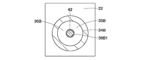
回転規制部41は、スプール30の右端部32B3と右キャップ34Bとの間に設けられている。この回転規制部41は、スプール30が右キャップ34B内に向けて変位したときに、スプール30のスプール摺動穴23内における回転を規制するものである。また、回転規制部41は、スプール30の回転が規制されるまでは、スプール30のスプール摺動穴23内における回転を許容するものである。そして、回転規制部41は、右突出軸部42と、右筒状体43とにより構成されている。なお、ハウジング22を挟んで回転規制部41の反対側には、図示しない回転規制部が回転規制部41と左,右方向で対称形状に設けられている。   The rotation restricting portion 41 is provided between the right end portion 32B3 of the spool 30 and the right cap 34B. The rotation restricting portion 41 restricts the rotation of the spool 30 in the spool sliding hole 23 when the spool 30 is displaced toward the right cap 34B. The rotation restricting portion 41 allows the rotation of the spool 30 in the spool sliding hole 23 until the rotation of the spool 30 is restricted. The rotation restricting portion 41 includes a right protruding shaft portion 42 and a right cylindrical body 43. In addition, on the opposite side of the rotation restricting portion 41 across the housing 22, a rotation restricting portion (not shown) is provided symmetrically with the rotation restricting portion 41 in the left and right directions.

右突出軸部42は、スプール30の右端部32B3に設けられ、右キャップ34B内に向けて軸方向に突出するものである。この右突出軸部42は、円柱体からなり右側ランド32Bに一体形成され、右ばね受36Bの貫通孔36B1を挿通している。この場合、右突出軸部42は、スプール30の一部を構成するものである。   The right protruding shaft portion 42 is provided at the right end portion 32B3 of the spool 30 and protrudes in the axial direction toward the right cap 34B. The right protruding shaft portion 42 is formed of a cylindrical body, is integrally formed with the right land 32B, and is inserted through the through hole 36B1 of the right spring receiver 36B. In this case, the right protruding shaft portion 42 constitutes a part of the spool 30.

右嵌合部としての右筒状体43は、右キャップ34Bの底部34B1側で右パイロット油室35B内に突出して設けられている。この右筒状体43は、右突出軸部42に対応した位置に配設され、スプール30が右方向に変位したときに右突出軸部42が進退可能に挿嵌されるものである。そして、右筒状体43は、その内径が右突出軸部42の外径にほぼ等しい寸法に形成され、両者間には摩擦抵抗が発生するものである。   The right tubular body 43 as the right fitting portion is provided to protrude into the right pilot oil chamber 35B on the bottom 34B1 side of the right cap 34B. The right cylindrical body 43 is disposed at a position corresponding to the right protruding shaft portion 42, and is inserted into the right protruding shaft portion 42 so as to advance and retract when the spool 30 is displaced in the right direction. The right cylindrical body 43 is formed so that the inner diameter thereof is substantially equal to the outer diameter of the right protruding shaft portion 42, and a frictional resistance is generated therebetween.

また、右筒状体43には、右キャップ34Bの底部34B1側で周方向に1個または複数個の油孔44(1個のみ図示)が形成されている。この油孔44は、右筒状体43の内外を右パイロット油室35Bに常時連通させている。これにより、右突出軸部42が右筒状体43内に挿嵌されたときに、右筒状体43内の作動油を右パイロット油室35Bに逃すことができる。   The right cylindrical body 43 is formed with one or a plurality of oil holes 44 (only one is shown) in the circumferential direction on the bottom 34B1 side of the right cap 34B. The oil hole 44 always communicates the inside and outside of the right cylindrical body 43 with the right pilot oil chamber 35B. Accordingly, when the right protruding shaft portion 42 is inserted into the right cylindrical body 43, the hydraulic oil in the right cylindrical body 43 can be released to the right pilot oil chamber 35B.

オペレータが操作レバー11Aを傾転操作して、スプール30が中立位置(図9の状態)から右方向に変位したときに、右突出軸部42が右筒状体43に嵌合するまでは、スプール30の回転が可能となっている。スプール30が回転することにより、作動油の流れに変化を与えることができるので、例えばノッチ32B2で発生した気泡の破裂による衝撃圧を分散させることができる。これにより、ハウジング22の浸食を抑制することができる。   When the operator tilts the operation lever 11A and the spool 30 is displaced in the right direction from the neutral position (state of FIG. 9), until the right protruding shaft portion 42 is fitted to the right cylindrical body 43, The spool 30 can be rotated. As the spool 30 rotates, it is possible to change the flow of the hydraulic oil, so that it is possible to disperse the impact pressure caused by, for example, bursting of bubbles generated in the notch 32B2. Thereby, erosion of the housing 22 can be suppressed.

オペレータが操作レバー11Aをさらに傾転操作すると、スプール30は、回転を増加させながら、さらに右方向に摺動変位する。そして、右突出軸部42が右筒状体43内に進入し始める。これにより、右突出軸部42は、右筒状体43の内周面に摺接して抵抗力が与えられ、ひいてはスプール30に回転規制力を与えることができる。   When the operator further tilts the operation lever 11A, the spool 30 slides further to the right while increasing the rotation. Then, the right protruding shaft portion 42 starts to enter the right cylindrical body 43. Thereby, the right protruding shaft portion 42 is slidably brought into contact with the inner peripheral surface of the right cylindrical body 43 to be given a resistance force, and as a result, a rotation restricting force can be given to the spool 30.

さらに操作レバー11Aが傾転操作されると、スプール30は、回転規制部41(右突出軸部42、右筒状体43)により回転が規制された状態で右方向に摺動変位し、図12に示すように、右突出軸部42が右キャップ34Bの底部34B1に当接してスプール30のストロークエンドとなる。この場合、スプール30が右方向に摺動変位するに従って、右突出軸部42と右筒状体43との接触面積が徐々に大きくなる。これにより、右突出軸部42には、徐々に大きな抵抗力が与えられ、ひいてはスプール30に与える回転規制力を増大させることができる。   When the operation lever 11A is further tilted, the spool 30 is slid to the right in a state where the rotation is restricted by the rotation restricting portion 41 (the right protruding shaft portion 42, the right cylindrical body 43). 12, the right protruding shaft portion 42 comes into contact with the bottom portion 34 </ b> B <b> 1 of the right cap 34 </ b> B and becomes the stroke end of the spool 30. In this case, as the spool 30 slides and displaces in the right direction, the contact area between the right protruding shaft portion 42 and the right cylindrical body 43 gradually increases. As a result, a large resistance force is gradually applied to the right protruding shaft portion 42, and as a result, the rotation restricting force applied to the spool 30 can be increased.

かくして、第2の実施の形態においても第1の実施の形態と同様に、キャビテーションによる気泡の衝撃圧と、スプール30の過剰な回転によるスプール30とハウジング22との摩耗との両方を抑制することができるので、スプール弁装置21の寿命を向上させることができる。特に、第2の実施の形態では、スプール30のストローク量の増加に伴い、スプール30の回転を規制する力が徐々に強まる。これにより、スプール30の回転を滑らかに停止させることができ、スプール30にかかる衝撃を抑制することができる。   Thus, in the second embodiment, as in the first embodiment, both the impact pressure of bubbles due to cavitation and the wear of the spool 30 and the housing 22 due to excessive rotation of the spool 30 are suppressed. Therefore, the life of the spool valve device 21 can be improved. In particular, in the second embodiment, as the stroke amount of the spool 30 increases, the force that regulates the rotation of the spool 30 gradually increases. Thereby, rotation of the spool 30 can be smoothly stopped, and an impact applied to the spool 30 can be suppressed.

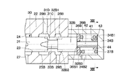
次に、図14、図15は、本発明の第3の実施の形態を示している。第3の実施の形態の特徴は、スプールがキャップ内に向けて変位したときに加えて、スプールが中立位置にあるときにもスプールの回転を規制したことにある。なお、本実施の形態では、第1の実施形態と同一の構成要素に同一符号を付し、その説明を省略するものとする。   Next, FIG. 14 and FIG. 15 show a third embodiment of the present invention. The feature of the third embodiment resides in that the rotation of the spool is restricted when the spool is in the neutral position in addition to when the spool is displaced toward the cap. In the present embodiment, the same components as those in the first embodiment are denoted by the same reference numerals, and the description thereof is omitted.

右キャップ51は、スプール摺動穴23の軸方向の右端部23Bに位置してハウジング22に設けられている。この右キャップ51は、有底筒状に形成され、スプール摺動穴23の右端部23Bを閉塞するものである。右キャップ51には、パイロット管路20Bの接続ポート34B2が設けられている。そして、右キャップ51の内部には、スプール30を軸方向に摺動変位させるための右パイロット油室52が形成されている。また、右キャップ51の内周側には、径方向内側に向けて突出する後述の底部側突出部58と、中央側突出部60とが右キャップ51に一体形成されている。なお、ハウジング22を挟んで右キャップ51の反対側には、図示しない左キャップが右キャップ51と左,右方向で対称形状に設けられている。   The right cap 51 is provided in the housing 22 at the right end 23 </ b> B in the axial direction of the spool sliding hole 23. The right cap 51 is formed in a bottomed cylindrical shape and closes the right end 23B of the spool sliding hole 23. The right cap 51 is provided with a connection port 34B2 of the pilot pipeline 20B. In the right cap 51, a right pilot oil chamber 52 for sliding the spool 30 in the axial direction is formed. Further, on the inner peripheral side of the right cap 51, a bottom-side protruding portion 58, which will be described later, protruding inward in the radial direction, and a center-side protruding portion 60 are integrally formed with the right cap 51. On the opposite side of the right cap 51 with the housing 22 in between, a left cap (not shown) is provided symmetrically with the right cap 51 in the left and right directions.

右スプリング53は、右キャップ51内に配設されたものである。この右スプリング53は、後述する右突出軸部55のスプリング取付凹部56の底部と右キャップ51の底部との間に設けられている。右スプリング53は、スプール30を中立位置に向けて付勢している。即ち、右スプリング53は、スプール30を中立位置に戻すためのセンタリング用のばね部材である。なお、左キャップ内にも図示しない左スプリングが設けられている。   The right spring 53 is disposed in the right cap 51. The right spring 53 is provided between a bottom portion of a spring mounting recess 56 of the right protruding shaft portion 55 described later and a bottom portion of the right cap 51. The right spring 53 biases the spool 30 toward the neutral position. That is, the right spring 53 is a centering spring member for returning the spool 30 to the neutral position. A left spring (not shown) is also provided in the left cap.

回転規制部54は、スプール30の右端部32B3と右キャップ51との間に設けられている。この回転規制部54は、スプール30が右キャップ51内に向けて変位したときに、スプール30のスプール摺動穴23内における回転を規制するものである。また、回転規制部54は、スプール30の回転が規制されるまでは、スプール30のスプール摺動穴23内における回転を許容するものである。そして、回転規制部54は、右突出軸部55に形成された環状突部57と右キャップ51に形成された底部側突出部58とにより構成されている。なお、左キャップ内には、図示しない回転規制部が回転規制部54と左,右方向で対称形状に設けられている。   The rotation restricting portion 54 is provided between the right end portion 32B3 of the spool 30 and the right cap 51. The rotation restricting portion 54 restricts the rotation of the spool 30 in the spool sliding hole 23 when the spool 30 is displaced toward the right cap 51. The rotation restricting portion 54 allows the rotation of the spool 30 in the spool sliding hole 23 until the rotation of the spool 30 is restricted. The rotation restricting portion 54 includes an annular protrusion 57 formed on the right protrusion shaft portion 55 and a bottom side protrusion portion 58 formed on the right cap 51. In the left cap, a rotation restricting portion (not shown) is provided symmetrically with the rotation restricting portion 54 in the left and right directions.

右突出軸部55は、スプール30の右端部32B3に設けられ、右キャップ51内に向けて軸方向に突出するものである。この右突出軸部55は、右側ランド32Bに一体形成されている。この場合、右突出軸部55は、スプール30の一部を構成するものである。右突出軸部55には、右端側から軸方向に凹むスプリング取付凹部56が穿設されている。このスプリング取付凹部56の底部と右キャップ51の底部との間には、右スプリング53が配設されている。   The right protruding shaft portion 55 is provided at the right end portion 32 </ b> B <b> 3 of the spool 30 and protrudes in the axial direction toward the right cap 51. The right protruding shaft portion 55 is integrally formed with the right land 32B. In this case, the right protruding shaft portion 55 constitutes a part of the spool 30. The right protruding shaft portion 55 is provided with a spring mounting recess 56 that is recessed in the axial direction from the right end side. A right spring 53 is disposed between the bottom of the spring mounting recess 56 and the bottom of the right cap 51.

右突出軸部55の外周側には、径方向外側に向けて突出する環状突部57が形成されている。この環状突部57は、軸方向に所定の厚さ寸法を有しており、後述する底部側突出部58および中央側突出部60に摺接する構成となっている。環状突部57、底部側突出部58、中央側突出部60のそれぞれの軸方向の厚さ寸法は、スプール30のストロークのうち、回転を規制する範囲と回転を許容する範囲との関係により適宜設定される。   On the outer peripheral side of the right protruding shaft portion 55, an annular protrusion 57 that protrudes outward in the radial direction is formed. The annular protrusion 57 has a predetermined thickness dimension in the axial direction, and is configured to be in sliding contact with a bottom-side protrusion 58 and a center-side protrusion 60 described later. The axial thickness of each of the annular protrusion 57, the bottom-side protrusion 58, and the center-side protrusion 60 is appropriately determined depending on the relationship between the range in which rotation is restricted and the range in which rotation is allowed, of the stroke of the spool 30 Is set.

底部側突出部58は、右キャップ51の底部側の内周面から径方向内側に向けて突出し、右キャップ51に一体形成されている。この底部側突出部58は、右突出軸部55の環状突部57に対応して形成されている。即ち、底部側突出部58は、スプール30が右方向に摺動変位してストロークエンドに近付いたときに、環状突部57と摺接して右突出軸部55に抵抗力を与え、ひいてはスプール30に回転規制力を与えるものである。   The bottom side protrusion 58 protrudes radially inward from the inner peripheral surface of the right cap 51 on the bottom side, and is integrally formed with the right cap 51. The bottom side protrusion 58 is formed corresponding to the annular protrusion 57 of the right protrusion shaft portion 55. That is, when the spool 30 slides rightward and approaches the stroke end, the bottom-side protruding portion 58 slides against the annular protruding portion 57 to apply a resistance force to the right protruding shaft portion 55, and thus the spool 30. It gives a rotation restricting power to.

他の回転規制部59は、スプール30の右端部32B3と右キャップ51との間に設けられている。他の回転規制部59は、スプール30が中立位置にあるときに、スプール30のスプール摺動穴23内における回転を規制するものである。そして、他の回転規制部59は、右突出軸部55に形成された環状突部57と右キャップ51に形成された中央側突出部60とにより構成されている。なお、左キャップ内には、図示しない他の回転規制部が他の回転規制部59と左,右方向で対称形状に設けられている。   The other rotation restricting portion 59 is provided between the right end portion 32B3 of the spool 30 and the right cap 51. The other rotation restricting portion 59 restricts the rotation of the spool 30 in the spool sliding hole 23 when the spool 30 is in the neutral position. The other rotation restricting portion 59 includes an annular protrusion 57 formed on the right protrusion shaft portion 55 and a center side protrusion 60 formed on the right cap 51. In the left cap, another rotation restricting portion (not shown) is provided symmetrically with the other rotation restricting portion 59 in the left and right directions.

中央側突出部60は、右キャップ51の軸方向中央部の内周面から径方向内側に向けて突出し、右キャップ51に一体形成されている。この中央側突出部60は、右突出軸部55の環状突部57に対応して形成され、かつスプール30が中立位置にあるときに環状突部57と当接する位置に設けられている。即ち、中央側突出部60は、スプール30が中立位置にあるときに、環状突部57と摺接して右突出軸部55に抵抗力を与え、ひいてはスプール30に回転規制力を与えるものである。   The center-side protruding portion 60 protrudes radially inward from the inner peripheral surface of the center portion in the axial direction of the right cap 51 and is integrally formed with the right cap 51. The central projecting portion 60 is formed corresponding to the annular projecting portion 57 of the right projecting shaft portion 55, and is provided at a position where it comes into contact with the annular projecting portion 57 when the spool 30 is in the neutral position. That is, when the spool 30 is in the neutral position, the center side protruding portion 60 is in sliding contact with the annular protruding portion 57 to give a resistance force to the right protruding shaft portion 55 and to give a rotation restricting force to the spool 30. .

このように構成された第3の実施の形態では、スプール30が中立位置にあるときには、右突出軸部55の環状突部57が中央側突出部60に広い面積で接触することにより、右突出軸部55に大きな抵抗力を与えてスプール30の回転を規制している。そして、スプール30が右方向に摺動変位すると、環状突部57と中央側突出部60との接触面積が徐々に小さくなる。これにより、右突出軸部55に与えられる抵抗力が徐々に弱くなるので、スプール30の回転が許容される。さらに、スプール30が右方向に摺動変位してストロークエンドに近付くと、環状突部57と底部側突出部58との接触面積が徐々に大きくなる。これにより、右突出軸部55には、徐々に大きな抵抗力が与えられ、ひいてはスプール30に与える回転規制力を増大させることができる。   In the third embodiment configured as described above, when the spool 30 is in the neutral position, the annular protrusion 57 of the right protrusion shaft part 55 contacts the center-side protrusion part 60 over a wide area, so that the right protrusion A large resistance is applied to the shaft portion 55 to restrict the rotation of the spool 30. When the spool 30 is slid in the right direction, the contact area between the annular protrusion 57 and the central protrusion 60 gradually decreases. As a result, the resistance force applied to the right protruding shaft portion 55 gradually decreases, so that the spool 30 is allowed to rotate. Further, when the spool 30 slides rightward and approaches the stroke end, the contact area between the annular protrusion 57 and the bottom-side protrusion 58 gradually increases. As a result, a large resistance force is gradually applied to the right protruding shaft portion 55, and as a result, the rotation restricting force applied to the spool 30 can be increased.

かくして、第3の実施の形態においても第1の実施の形態と同様に、キャビテーションによる気泡の衝撃圧と、スプール30の過剰な回転によるスプール30とハウジング22との摩耗との両方を抑制することができるので、スプール弁装置21の寿命を向上させることができる。また、第3の実施の形態では、スプール30が中立位置にあるときにもスプール30の回転を規制している。これにより、スプール30が中立位置にあるときにも、スプール30とハウジング22との摩耗を抑制することができる。   Thus, in the third embodiment, as in the first embodiment, both the impact pressure of the bubbles due to cavitation and the wear of the spool 30 and the housing 22 due to excessive rotation of the spool 30 are suppressed. Therefore, the life of the spool valve device 21 can be improved. In the third embodiment, the rotation of the spool 30 is also restricted when the spool 30 is in the neutral position. Thereby, even when the spool 30 is in the neutral position, wear of the spool 30 and the housing 22 can be suppressed.

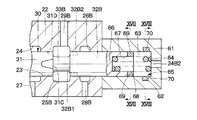
次に、図16ないし図18は、本発明の第4の実施の形態を示している。第4の実施の形態の特徴は、磁力によりスプールの回転を規制したことにある。なお、本実施の形態では、第1の実施形態と同一の構成要素に同一符号を付し、その説明を省略するものとする。   Next, FIGS. 16 to 18 show a fourth embodiment of the present invention. The feature of the fourth embodiment resides in that the rotation of the spool is restricted by the magnetic force. In the present embodiment, the same components as those in the first embodiment are denoted by the same reference numerals, and the description thereof is omitted.

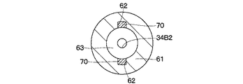
右キャップ61は、スプール摺動穴23の軸方向の右端部23Bに位置してハウジング22に設けられている。この右キャップ61は、例えば非磁性材料を用いて有底筒状に形成され、スプール摺動穴23の右端部23Bを閉塞するものである。右キャップ61の底部には、パイロット管路20Bの接続ポート34B2が設けられている。   The right cap 61 is provided in the housing 22 at the right end 23 </ b> B in the axial direction of the spool sliding hole 23. The right cap 61 is formed in a bottomed cylindrical shape using, for example, a nonmagnetic material, and closes the right end portion 23 </ b> B of the spool sliding hole 23. At the bottom of the right cap 61, a connection port 34B2 of the pilot pipeline 20B is provided.

また、右キャップ61の内周側で底部側には、周方向に離間して複数個(例えば、2個)の磁石取付凹部62が形成されている。この磁石取付凹部62には、後述のキャップ側磁石70が固着される。そして、右キャップ61の内部には、スプール30を軸方向に摺動変位させるための右パイロット油室63が形成されている。なお、ハウジング22を挟んで右キャップ61の反対側には、図示しない左キャップが右キャップ61と左,右方向で対称形状に設けられている。   A plurality of (for example, two) magnet mounting recesses 62 are formed on the inner peripheral side and the bottom side of the right cap 61 so as to be spaced apart from each other in the circumferential direction. A cap-side magnet 70 described later is fixed to the magnet mounting recess 62. A right pilot oil chamber 63 is formed in the right cap 61 for slidingly displacing the spool 30 in the axial direction. A left cap (not shown) is provided symmetrically with the right cap 61 in the left and right directions on the opposite side of the right cap 61 across the housing 22.

右スプリング64は、右キャップ61内に配設されたものである。この右スプリング64は、後述する右突出軸部66のスプリング取付凹部67の底部と右キャップ61の底部との間に設けられている。右スプリング64は、スプール30を中立位置に向けて付勢している。即ち、右スプリング64は、スプール30を中立位置に戻すためのセンタリング用のばね部材である。なお、左キャップ内にも図示しない左スプリングが設けられている。   The right spring 64 is disposed in the right cap 61. The right spring 64 is provided between a bottom portion of a spring mounting recess 67 of the right protruding shaft portion 66 described later and a bottom portion of the right cap 61. The right spring 64 biases the spool 30 toward the neutral position. That is, the right spring 64 is a centering spring member for returning the spool 30 to the neutral position. A left spring (not shown) is also provided in the left cap.

回転規制部65は、スプール30の右端部32B3と右キャップ61との間に設けられている。この回転規制部65は、スプール30が右キャップ61内に向けて変位したときに、スプール30のスプール摺動穴23内における回転を規制するものである。また、回転規制部65は、スプール30の回転が規制されるまでは、スプール30のスプール摺動穴23内における回転を許容するものである。そして、回転規制部65は、右突出軸部66に設けられた軸側磁石69と右キャップ61に設けられたキャップ側磁石70とにより構成されている。なお、左キャップ内には、図示しない回転規制部が回転規制部65と左,右方向で対称形状に設けられている。   The rotation restricting portion 65 is provided between the right end portion 32B3 of the spool 30 and the right cap 61. The rotation restricting portion 65 restricts the rotation of the spool 30 in the spool sliding hole 23 when the spool 30 is displaced toward the right cap 61. The rotation restricting portion 65 allows the rotation of the spool 30 in the spool sliding hole 23 until the rotation of the spool 30 is restricted. The rotation restricting portion 65 includes a shaft-side magnet 69 provided on the right protruding shaft portion 66 and a cap-side magnet 70 provided on the right cap 61. In the left cap, a rotation restricting portion (not shown) is provided symmetrically with the rotation restricting portion 65 in the left and right directions.

右突出軸部66は、スプール30の右端部32B3に設けられ、右キャップ61内に向けて軸方向に突出するものである。この右突出軸部66は、例えば非磁性材料を用いて右側ランド32Bとほぼ同じ外径寸法を有して右側ランド32Bに一体形成されている。この場合、右突出軸部66は、スプール30の一部を構成するものである。右突出軸部66には、右端側から軸方向に凹むスプリング取付凹部67が穿設されている。このスプリング取付凹部67の底部と右キャップ61の底部との間には、右スプリング64が配設されている。また、右突出軸部66の右端側には、軸方向に凹む磁石取付凹部68が周方向に離間して複数個(例えば、2個)形成されている。   The right protruding shaft portion 66 is provided at the right end portion 32 </ b> B <b> 3 of the spool 30 and protrudes in the axial direction toward the right cap 61. The right protruding shaft portion 66 is formed integrally with the right land 32B using, for example, a non-magnetic material and having substantially the same outer diameter as the right land 32B. In this case, the right protruding shaft portion 66 constitutes a part of the spool 30. The right protruding shaft portion 66 is provided with a spring mounting recess 67 that is recessed in the axial direction from the right end side. A right spring 64 is disposed between the bottom of the spring mounting recess 67 and the bottom of the right cap 61. A plurality of (for example, two) magnet mounting recesses 68 that are recessed in the axial direction are formed on the right end side of the right protruding shaft portion 66 so as to be spaced apart in the circumferential direction.

軸側磁石69は、右突出軸部66の磁石取付凹部68に固着されている。一方、キャップ側磁石70は、右キャップ61の磁石取付凹部62に固着されている。軸側磁石69とキャップ側磁石70とは、その磁力によりスプール30の回転を規制するものである。具体的には、スプール30のストロークが小さいときには、軸側磁石69とキャップ側磁石70との距離が十分に離れているので磁力の影響が少なく、スプール30の回転を許容する。一方、スプール30がストロークエンドに近付いたときには、軸側磁石69とキャップ側磁石70との距離が近づくので磁力が強く働き、スプール30の回転を規制する。   The shaft side magnet 69 is fixed to the magnet mounting recess 68 of the right protruding shaft portion 66. On the other hand, the cap-side magnet 70 is fixed to the magnet mounting recess 62 of the right cap 61. The shaft-side magnet 69 and the cap-side magnet 70 regulate the rotation of the spool 30 by its magnetic force. Specifically, when the stroke of the spool 30 is small, the distance between the shaft-side magnet 69 and the cap-side magnet 70 is sufficiently large, so that the influence of the magnetic force is small and the spool 30 is allowed to rotate. On the other hand, when the spool 30 approaches the stroke end, the distance between the shaft-side magnet 69 and the cap-side magnet 70 approaches, so that the magnetic force acts strongly and restricts the rotation of the spool 30.

かくして、第4の実施の形態においても第1の実施の形態と同様に、キャビテーションによる気泡の衝撃圧と、スプール30の過剰な回転によるスプール30とハウジング22との摩耗との両方を抑制することができるので、スプール弁装置21の寿命を向上させることができる。特に、第4の実施の形態では、磁力によりスプール30の回転を規制しているので、スプール30にかかる衝撃圧を低減することができる。また、右キャップ61と右突出軸部66とに磁石(キャップ側磁石70、軸側磁石69)を設けるだけでよいので、加工を簡単に行うことができる。   Thus, also in the fourth embodiment, as in the first embodiment, both the impact pressure of bubbles due to cavitation and the wear of the spool 30 and the housing 22 due to excessive rotation of the spool 30 are suppressed. Therefore, the life of the spool valve device 21 can be improved. In particular, in the fourth embodiment, since the rotation of the spool 30 is restricted by the magnetic force, the impact pressure applied to the spool 30 can be reduced. In addition, since it is only necessary to provide magnets (cap-side magnet 70 and shaft-side magnet 69) on the right cap 61 and the right protruding shaft portion 66, processing can be performed easily.

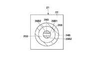
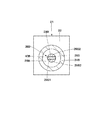
次に、図19、図20は、本発明の第5の実施の形態を示している。第5の実施の形態の特徴は、アクチュエータポートとタンクポートとの間を連通させるノッチをポンプポートとアクチュエータポートとの間を連通させるノッチに対して周方向にずらして配置したことにある。なお、本実施の形態では、第1、第2の実施形態と同一の構成要素に同一符号を付し、その説明を省略するものとする。   Next, FIGS. 19 and 20 show a fifth embodiment of the present invention. The feature of the fifth embodiment resides in that the notch that communicates between the actuator port and the tank port is shifted in the circumferential direction with respect to the notch that communicates between the pump port and the actuator port. In the present embodiment, the same components as those in the first and second embodiments are denoted by the same reference numerals, and the description thereof is omitted.

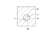
ノッチ71は、右側ランド32Bの左端側に軸方向に延びるように形成されている。このノッチ71は、周方向に離間して複数個(例えば2個)形成されている。ノッチ71は、右側油溝25Bと右端側油溝26Bとの間、即ち右アクチュエータポート29Bと右タンクポート28Bとの間を流れる圧油を小流量で連通させるものである。   The notch 71 is formed on the left end side of the right land 32B so as to extend in the axial direction. A plurality of (for example, two) notches 71 are formed apart from each other in the circumferential direction. The notch 71 communicates the pressure oil flowing between the right oil groove 25B and the right end oil groove 26B, that is, between the right actuator port 29B and the right tank port 28B, with a small flow rate.

そして、ノッチ71は、中央ランド31の右端部31Cに形成され、ポンプポート27と右アクチュエータポート29Bとの間を連通させるノッチ31B,31D(31Dのみ図示)に対して周方向にずらした位置に配置されている。これにより、スプール30の回転を許容するストローク位置で、スプール30を円滑に回転させることができる。   The notch 71 is formed at the right end 31C of the center land 31 and is shifted in the circumferential direction with respect to the notches 31B and 31D (only 31D shown) that communicate between the pump port 27 and the right actuator port 29B. Has been placed. Thereby, the spool 30 can be smoothly rotated at a stroke position that allows the spool 30 to rotate.

その結果、キャビテーションによる気泡を分散させることができ、気泡の破裂による衝撃圧をハウジング22の同じ位置に集中させるのを抑制することができる。なお、図示しない左側ランドに形成されたノッチも、中央ランド31に形成されたノッチ31B,31Dに対して周方向にずらした位置に配設されている。   As a result, the bubbles due to cavitation can be dispersed, and the impact pressure due to the bursting of the bubbles can be suppressed from being concentrated at the same position of the housing 22. The notch formed in the left land (not shown) is also arranged at a position shifted in the circumferential direction with respect to the notches 31B and 31D formed in the central land 31.

なお、上述した第1、第2の実施の形態では、スプール30と左,右のスプリング37A,37Bの摺動部材として左,右のばね受36A,36Bを設けた場合を例に挙げて説明した。しかし、本発明はこれに限らず、例えば図21に示す変形例のように、スプール30の右端部32B3と右スプリング37Bとの間に摺動部材としての玉軸受81を設けてもよい。これにより、スプール30と右スプリング37Bとの間の摺動抵抗を小さくすることができるので、スプール30を円滑に回転させることができる。また、スプール30と右スプリング37Bとの摩耗も低減することができる。なお、左ばね受36Aについても同様に玉軸受を用いてもよい。   In the first and second embodiments described above, the case where the left and right spring receivers 36A and 36B are provided as the sliding members of the spool 30 and the left and right springs 37A and 37B will be described as an example. did. However, the present invention is not limited to this, and a ball bearing 81 as a sliding member may be provided between the right end portion 32B3 of the spool 30 and the right spring 37B, for example, as in a modification shown in FIG. Thereby, since the sliding resistance between the spool 30 and the right spring 37B can be reduced, the spool 30 can be smoothly rotated. Further, wear of the spool 30 and the right spring 37B can be reduced. Similarly, a ball bearing may be used for the left spring receiver 36A.

また、各実施の形態では、ブームシリンダ4D用のスプール弁装置21を例に挙げて説明した。しかし、本発明はこれに限らず、例えばアームシリンダ4E、バケットシリンダ4F、および油圧モータ等のスプール弁装置に適用してもよい。また、これ以外に圧力制御弁、流量制御弁等のスプール弁装置に適用することができる。   In each embodiment, the spool valve device 21 for the boom cylinder 4D has been described as an example. However, the present invention is not limited to this, and may be applied to spool valve devices such as the arm cylinder 4E, the bucket cylinder 4F, and a hydraulic motor, for example. In addition, it can be applied to spool valve devices such as pressure control valves and flow rate control valves.

21 スプール弁装置、22 ハウジング、23 スプール摺動穴、23A 左端部、23B 右端部、27 ポンプポート、28A 左タンクポート、28B 右タンクポート、29A 左アクチュエータポート、29B 右アクチュエータポート、30 スプール、31 中央ランド、31B ノッチ、31D ノッチ、32A 左側ランド、32A2 ノッチ、32A3 左端部、32B 右側ランド、32B2,71 ノッチ、32B3 右端部、34A 左キャップ、34A1 底部、34B 右キャップ、34B1 底部、36A 左ばね受(摺動部材)、36B 右ばね受(摺動部材)、37A 左スプリング、37B 右スプリング、38A,38B,41,54,65 回転規制部、39A 左突出軸部、39B,42 右突出軸部、40A 左嵌合突部(嵌合部)、40B 右嵌合突部(嵌合部)、43 右筒状体(嵌合部)、59 他の回転規制部、81 玉軸受(摺動部材)   21 spool valve device, 22 housing, 23 spool sliding hole, 23A left end, 23B right end, 27 pump port, 28A left tank port, 28B right tank port, 29A left actuator port, 29B right actuator port, 30 spool, 31 Center land, 31B notch, 31D notch, 32A left land, 32A2 notch, 32A3 left end, 32B right land, 32B2, 71 notch, 32B3 right end, 34A left cap, 34A1 bottom, 34B right cap, 34B1 bottom, 36A left spring Support (sliding member), 36B Right spring support (sliding member), 37A Left spring, 37B Right spring, 38A, 38B, 41, 54, 65 Rotation restricting portion, 39A Left protruding shaft portion, 39B, 42 Right protruding shaft Part, 40A left Fitting protrusion (fitting part), 40B Right fitting protrusion (fitting part), 43 Right cylindrical body (fitting part), 59 Other rotation restricting part, 81 Ball bearing (sliding member)

Claims (6)

スプール摺動穴を有し、該スプール摺動穴の軸方向にそれぞれ離間してポンプポート、タンクポート、およびアクチュエータポートが設けられた筒状のハウジングと、
前記ハウジングのスプール摺動穴に摺動可能に挿嵌され前記アクチュエータポートを前記ポンプポートと前記タンクポートとのいずれかに連通または遮断させるための複数のランドが設けられたスプールと、
前記スプール摺動穴の軸方向の端部に位置して前記ハウジングに設けられ、内部に前記スプールを軸方向に摺動変位させるためのパイロット油室を形成するキャップと、
前記キャップ内に配設され、前記スプールを中立位置に向けて付勢するセンタリング用のスプリングとを備え、
前記スプールの各ランドには、前記ポンプポートと前記アクチュエータポートとの間または前記アクチュエータポートと前記タンクポートとの間を小流量で連通させるノッチを設けてなるスプール弁装置において、
前記スプールの端部と前記キャップとの間には、前記スプールが前記キャップ内に向けて変位したときに、前記スプールの前記スプール摺動穴内における回転を規制する回転規制部を設け、
前記回転規制部により前記スプールの回転が規制されるまでは、前記スプールの前記スプール摺動穴内における回転を許容する構成としたことを特徴とするスプール弁装置。
A cylindrical housing having a spool sliding hole and provided with a pump port, a tank port, and an actuator port spaced apart from each other in the axial direction of the spool sliding hole;
A spool that is slidably fitted into a spool sliding hole of the housing, and is provided with a plurality of lands for communicating or blocking the actuator port with either the pump port or the tank port;
A cap that is provided in the housing at an end portion in the axial direction of the spool sliding hole, and that forms a pilot oil chamber for slidingly displacing the spool in the axial direction therein;
A centering spring disposed in the cap and biasing the spool toward a neutral position;
In each spool land, a notch for providing a small flow rate between the pump port and the actuator port or between the actuator port and the tank port is provided.
Provided between the end of the spool and the cap is a rotation restricting portion that restricts rotation of the spool in the spool sliding hole when the spool is displaced toward the cap.
The spool valve device is configured to allow rotation of the spool in the spool sliding hole until the rotation of the spool is restricted by the rotation restricting portion.
前記スプールの端部と前記センタリング用のスプリングとの間には、両者の相対回転を許す摺動部材が設けられる構成としてなる請求項1に記載のスプール弁装置。   2. The spool valve device according to claim 1, wherein a sliding member is provided between the end of the spool and the centering spring to allow relative rotation between the two. 前記回転規制部は、前記スプールの端部に設けられ前記キャップ内に向けて軸方向に突出する突出軸部と、前記キャップの底部側に設けられ、前記スプールが変位したとき前記突出軸部が進退可能に嵌合する嵌合部とにより構成してなる請求項1または2に記載のスプール弁装置。   The rotation restricting portion is provided at an end portion of the spool and protrudes in the axial direction toward the inside of the cap, and provided on the bottom side of the cap. When the spool is displaced, the protruding shaft portion is The spool valve device according to claim 1, wherein the spool valve device is configured by a fitting portion that is fitted so as to be able to advance and retreat. 前記回転規制部の前記嵌合部は、前記突出軸部が進退可能に挿嵌される筒状体からなり、
前記突出軸部と前記筒状体とは、前記突出軸部が前記筒状体内に進入し両者の接触面積が大きくなるに応じて回転規制力を増大させる構成としてなる請求項3に記載のスプール弁装置。
The fitting portion of the rotation restricting portion is formed of a cylindrical body into which the protruding shaft portion is inserted and retracted.
4. The spool according to claim 3, wherein the protruding shaft portion and the cylindrical body are configured to increase a rotation restricting force as the protruding shaft portion enters the cylindrical body and a contact area between both increases. Valve device.
前記各ランドにそれぞれ設けられた複数のノッチのうち前記アクチュエータポートと前記タンクポートとの間を連通させるノッチは、前記ポンプポートと前記アクチュエータポートとの間を連通するノッチに対して周方向にずらした位置に配置される構成としてなる請求項1,2,3または4に記載のスプール弁装置。   Of the plurality of notches provided in each land, the notch communicating between the actuator port and the tank port is shifted in the circumferential direction with respect to the notch communicating between the pump port and the actuator port. The spool valve device according to claim 1, 2, 3 or 4, wherein the spool valve device is arranged at a different position. 前記スプールの端部と前記キャップとの間には、前記スプールが中立位置にあるときに該スプールの前記スプール摺動内における回転を規制する他の回転規制部を設ける構成としてなる請求項1,2,3,4または5に記載のスプール弁装置。   2. A configuration in which another rotation restricting portion is provided between the end portion of the spool and the cap to restrict the rotation of the spool within the spool sliding when the spool is in a neutral position. The spool valve device according to 2, 3, 4 or 5.
JP2015121055A 2015-06-16 2015-06-16 Spool valve device Active JP6490507B2 (en)

Priority Applications (1)

Application Number Priority Date Filing Date Title
JP2015121055A JP6490507B2 (en) 2015-06-16 2015-06-16 Spool valve device

Applications Claiming Priority (1)

Application Number Priority Date Filing Date Title
JP2015121055A JP6490507B2 (en) 2015-06-16 2015-06-16 Spool valve device

Publications (2)

Publication Number Publication Date
JP2017003100A true JP2017003100A (en) 2017-01-05
JP6490507B2 JP6490507B2 (en) 2019-03-27

Family

ID=57751867

Family Applications (1)

Application Number Title Priority Date Filing Date
JP2015121055A Active JP6490507B2 (en) 2015-06-16 2015-06-16 Spool valve device

Country Status (1)

Country Link
JP (1) JP6490507B2 (en)

Cited By (1)

* Cited by examiner, † Cited by third party
Publication number Priority date Publication date Assignee Title
CN110431338A (en) * 2017-03-17 2019-11-08 纳博特斯克有限公司 Slide valve

Citations (13)

* Cited by examiner, † Cited by third party
Publication number Priority date Publication date Assignee Title
JPS4919284B1 (en) * 1967-06-26 1974-05-16
US4238112A (en) * 1978-12-22 1980-12-09 Rexnord Inc. Spool spin prevention for hydraulic control valves
JPS60167271U (en) * 1984-04-13 1985-11-06 株式会社小松製作所 Control valve load pressure outlet
JPS6446582U (en) * 1987-09-16 1989-03-22
JPH01150005A (en) * 1987-11-04 1989-06-13 Robert Bosch Gmbh Hydraulic control valve
JPH03163274A (en) * 1989-11-21 1991-07-15 Kayaba Ind Co Ltd Spool valve
JPH03172602A (en) * 1989-11-30 1991-07-26 Kayaba Ind Co Ltd Spool valve
JPH0861521A (en) * 1994-08-24 1996-03-08 Tokimec Inc Spool type control valve
JPH08219300A (en) * 1995-02-08 1996-08-27 Nachi Fujikoshi Corp Spool rotation preventing structure of spool valve
JPH1163250A (en) * 1998-06-29 1999-03-05 Kayaba Ind Co Ltd Pressure compensation valve device
JP2002188603A (en) * 2000-12-20 2002-07-05 Kayaba Ind Co Ltd Switching valve
JP2003097739A (en) * 2001-09-27 2003-04-03 Shin Caterpillar Mitsubishi Ltd Structure for preventing rotation of spool
JP2008002663A (en) * 2006-06-26 2008-01-10 Hitachi Constr Mach Co Ltd Spool valve device

Patent Citations (13)

* Cited by examiner, † Cited by third party
Publication number Priority date Publication date Assignee Title
JPS4919284B1 (en) * 1967-06-26 1974-05-16
US4238112A (en) * 1978-12-22 1980-12-09 Rexnord Inc. Spool spin prevention for hydraulic control valves
JPS60167271U (en) * 1984-04-13 1985-11-06 株式会社小松製作所 Control valve load pressure outlet
JPS6446582U (en) * 1987-09-16 1989-03-22
JPH01150005A (en) * 1987-11-04 1989-06-13 Robert Bosch Gmbh Hydraulic control valve
JPH03163274A (en) * 1989-11-21 1991-07-15 Kayaba Ind Co Ltd Spool valve
JPH03172602A (en) * 1989-11-30 1991-07-26 Kayaba Ind Co Ltd Spool valve
JPH0861521A (en) * 1994-08-24 1996-03-08 Tokimec Inc Spool type control valve
JPH08219300A (en) * 1995-02-08 1996-08-27 Nachi Fujikoshi Corp Spool rotation preventing structure of spool valve
JPH1163250A (en) * 1998-06-29 1999-03-05 Kayaba Ind Co Ltd Pressure compensation valve device
JP2002188603A (en) * 2000-12-20 2002-07-05 Kayaba Ind Co Ltd Switching valve
JP2003097739A (en) * 2001-09-27 2003-04-03 Shin Caterpillar Mitsubishi Ltd Structure for preventing rotation of spool
JP2008002663A (en) * 2006-06-26 2008-01-10 Hitachi Constr Mach Co Ltd Spool valve device

Cited By (1)

* Cited by examiner, † Cited by third party
Publication number Priority date Publication date Assignee Title
CN110431338A (en) * 2017-03-17 2019-11-08 纳博特斯克有限公司 Slide valve

Also Published As

Publication number Publication date
JP6490507B2 (en) 2019-03-27

Similar Documents

Publication Publication Date Title
US6389809B1 (en) Volume control valve of variable displacement hydraulic rotating machine
JP6178925B1 (en) Spool valve, operating device, and work vehicle
JP5848721B2 (en) Buffer valve
JP2010513822A (en) Rotary hydraulic valve
WO2021059614A1 (en) Flow control valve
CN107061404B (en) Direction switching valve and hydraulic system
JP6490507B2 (en) Spool valve device
JP2007177821A (en) Hydraulic drive unit
CN111527313B (en) fluid pressure control device
US10816099B2 (en) Spool valve
JP6734825B2 (en) Spool valve device
JP6822930B2 (en) Flow control valve
JP5645236B2 (en) Electric oil hybrid drive unit
JP6248144B2 (en) Pump device
JP2011021625A (en) Hydraulic actuator driving device
JP6689808B2 (en) Operating device for hydraulic work machines
JP2019060373A (en) Hydraulic motor control device
JP6505630B2 (en) Direction control valve
JP6913659B2 (en) Spool valve device
JP7316423B2 (en) flow control valve
JP7349974B2 (en) Hydraulic control equipment and hydraulic equipment
WO2021172098A1 (en) Fluid pressure drive unit
JP2018119664A (en) Counter balance valve and fluid pressure control device comprising counter balance valve
JP6836487B2 (en) Control valve
JP2023091435A (en) Control valve and work machine including the same

Legal Events

Date Code Title Description
A621 Written request for application examination

Free format text: JAPANESE INTERMEDIATE CODE: A621

Effective date: 20180208

RD02 Notification of acceptance of power of attorney

Free format text: JAPANESE INTERMEDIATE CODE: A7422

Effective date: 20180208

A977 Report on retrieval

Free format text: JAPANESE INTERMEDIATE CODE: A971007

Effective date: 20181213

A131 Notification of reasons for refusal

Free format text: JAPANESE INTERMEDIATE CODE: A131

Effective date: 20190108

A521 Request for written amendment filed

Free format text: JAPANESE INTERMEDIATE CODE: A523

Effective date: 20190201

TRDD Decision of grant or rejection written
A01 Written decision to grant a patent or to grant a registration (utility model)

Free format text: JAPANESE INTERMEDIATE CODE: A01

Effective date: 20190226

A61 First payment of annual fees (during grant procedure)

Free format text: JAPANESE INTERMEDIATE CODE: A61

Effective date: 20190227

R150 Certificate of patent or registration of utility model

Ref document number: 6490507

Country of ref document: JP

Free format text: JAPANESE INTERMEDIATE CODE: R150