JP2017002642A - Roof structure of building, and construction method of roof structure - Google Patents
Roof structure of building, and construction method of roof structure Download PDFInfo
- Publication number
- JP2017002642A JP2017002642A JP2015119636A JP2015119636A JP2017002642A JP 2017002642 A JP2017002642 A JP 2017002642A JP 2015119636 A JP2015119636 A JP 2015119636A JP 2015119636 A JP2015119636 A JP 2015119636A JP 2017002642 A JP2017002642 A JP 2017002642A
- Authority
- JP
- Japan
- Prior art keywords
- roof
- roof unit
- unit
- units
- building
- Prior art date
- Legal status (The legal status is an assumption and is not a legal conclusion. Google has not performed a legal analysis and makes no representation as to the accuracy of the status listed.)
- Granted
Links
Images


Landscapes
- Conveying And Assembling Of Building Elements In Situ (AREA)
Abstract
Description
本発明は、建物の屋根構造及び屋根構造物の施工方法に関する。 The present invention relates to a roof structure of a building and a construction method of the roof structure.
例えば、コンビニエンスストアに代表される各種店舗用の建物では、建物本体の上に設置された複数の屋根ユニットによって屋根が構築されることが一般化されている。その複数の屋根ユニットはいずれも略長方形状をなし、建物の幅方向に沿って長辺部同士を隣り合わせるように複数並べられ、屋根が構築されている。 For example, in a building for various stores represented by a convenience store, it is general that a roof is constructed by a plurality of roof units installed on a building body. Each of the plurality of roof units has a substantially rectangular shape, and a plurality of roof units are arranged side by side so that the long side portions are adjacent to each other along the width direction of the building.
このような構成が採用されているのは、店舗等の建物の場合、構造が画一化され、短期間で建築する等の要求あり、それに応えるために建物構造が工業化されていることによる。そのため、屋根ユニットや建物本体の外壁部を構成する外壁ユニット等の建物構成部材は、工場にて製造される。製造されたその屋根ユニット等の建物構成部材は、トラック等の輸送手段を用いて建物の建築現場に運ばれる。そして、建築現場においてそれら建物構成部材が組み立てられて、建物が建築される。 The reason why such a configuration is adopted is that, in the case of a building such as a store, there is a demand for building a uniform structure and building in a short period of time, and the building structure is industrialized to meet this demand. Therefore, building components such as an outer wall unit that constitutes an outer wall portion of a roof unit or a building body are manufactured in a factory. The manufactured building components such as the roof unit are transported to the building construction site using a transportation means such as a truck. And these building structural members are assembled in a construction site, and a building is built.
ところで、トラック等の輸送手段で屋根ユニット等の建築構成部材を輸送する場合、その建築構成部材の寸法等には、各種法令によって輸送上の制約がかかる。特に、屋根ユニットに関しては、その長辺側の長さ寸法(長手寸法)に、例えばトラックの荷台に積載可能な大きさの範囲内といった制約がかかる。そのため、複数の屋根ユニットが一列に並べられて屋根が構成される場合、建物の奥行寸法は、積載可能な屋根ユニットの長手寸法よりも長くすることはできない。 By the way, when a building component such as a roof unit is transported by a transportation means such as a truck, the dimensions and the like of the building component are restricted in transportation due to various laws and regulations. In particular, with respect to the roof unit, the length (longitudinal dimension) on the long side is restricted, for example, within a size range that can be loaded on a truck bed. Therefore, when a roof is formed by arranging a plurality of roof units in a row, the depth dimension of the building cannot be longer than the longitudinal dimension of the stackable roof units.
そこで、屋根ユニットの配置構成を工夫することにより、屋根ユニットの長手寸法よりも長い奥行寸法を備えた建物が提案されている。その一例として、第1屋根ユニットの長辺部同士を隣り合せて並べた部分と、第2屋根ユニットの長手方向を建物の幅方向に沿うようにして並べた部分とを組み合わせ、それにより屋根を構築した建物がある(例えば特許文献1参照)。これにより、第2屋根ユニットの短辺側の寸法だけ、建物の奥行寸法が拡張されることになる。 Then, the building provided with the depth dimension longer than the longitudinal dimension of a roof unit by devising the arrangement configuration of a roof unit is proposed. As an example, a combination of a portion in which the long sides of the first roof unit are arranged side by side and a portion in which the longitudinal direction of the second roof unit is arranged along the width direction of the building is combined. There is a built building (see, for example, Patent Document 1). As a result, the depth dimension of the building is expanded by the dimension on the short side of the second roof unit.
しかしながら、上記のように従来提案されている建物の屋根では、その奥行寸法が拡張されたとしても、建物内部に柱や内壁部を設けて屋根ユニットを支持しなければならない。そのため、建物本体の奥行寸法が拡張されても、その屋内空間には柱や内壁部が存在するため、奥行寸法の長い、より広い空間を確保することができていない。このため、建物の屋内空間についても、奥行寸法をより長くして広い空間を確保することが求められていた。 However, in the roof of a conventionally proposed building as described above, even if the depth dimension is expanded, the roof unit must be supported by providing columns and inner walls in the building. Therefore, even if the depth dimension of the building main body is expanded, pillars and inner wall portions exist in the indoor space, and thus a wider space having a long depth dimension cannot be secured. For this reason, also about the indoor space of a building, it was calculated | required that the depth dimension was lengthened and the wide space was ensured.
本発明は、上記事情に鑑みてなされたものであり、複数の屋根ユニットが横並びで連結されてなる建物の屋根構造であって、屋内空間をより広く確保することができる屋根構造を得ることを主たる目的とする。併せて、そのような屋根構造物を構築するための施工方法を得ることも目的とする。 This invention is made in view of the said situation, Comprising: It is the roof structure of the building where a plurality of roof units are connected side by side, Comprising: Obtaining the roof structure which can ensure indoor space more widely Main purpose. In addition, another object is to obtain a construction method for constructing such a roof structure.
以下、上記課題を解決するのに有効な手段等につき、必要に応じて作用、効果等を示しつつ説明する。 Hereinafter, means and the like effective for solving the above-described problems will be described while showing functions and effects as necessary.
第1の発明では、略直方体形状をなす複数の屋根ユニットが横並びで設けられてなり、前記複数の屋根ユニットは、複数の第1屋根ユニットと複数の第2屋根ユニットとを含む建物の屋根構造であって、長辺部同士を隣り合わせて並べて設けられた前記複数の第1屋根ユニットよりなる第1屋根ユニット構成部と、前記複数の第1屋根ユニットと同じ方向に並べて設けられた前記複数の第2屋根ユニットよりなる第2屋根ユニット構成部と、隣接する前記第1屋根ユニットと前記第2屋根ユニットとを連結する第1連結部材と、前記第1屋根ユニット同士の境界線と、前記第1屋根ユニット構成部及び前記第2屋根ユニット構成部の境界線とが交差する交差部分に設けられ、当該交差部分で互いに隣接し合う前記第1屋根ユニット及び前記第2屋根ユニット同士を連結する第2連結部材とを有することを特徴とする。 In the first invention, a plurality of roof units having a substantially rectangular parallelepiped shape are provided side by side, and the plurality of roof units include a plurality of first roof units and a plurality of second roof units. The first roof unit constituting part comprising the plurality of first roof units provided with the long side parts arranged side by side, and the plurality of the plurality of provided provided side by side in the same direction as the plurality of first roof units. A second roof unit component comprising a second roof unit, a first connecting member that connects the adjacent first roof unit and the second roof unit, a boundary line between the first roof units, and the first The first roof unit and the first roof unit, which are provided at an intersecting portion where a boundary line between the first roof unit component and the second roof unit component intersects, and are adjacent to each other at the intersecting portion. And having a second connecting member for connecting the roof unit together.
この第1の発明によれば、第1屋根ユニット同士の境界線と、第1屋根ユニット構成部及び第2屋根ユニット構成部の境界線とが交差する交差部分に、第2連結部材が設けられる。そのため、第1屋根ユニットと第2屋根ユニットとが第1連結部材によって連結されることに加え、第2連結部材により、交差部分において互いに隣接し合う第1屋根ユニット及び第2屋根ユニット同士が連結される。これにより、第1屋根ユニット及び第2屋根ユニットで構成される屋根構造全体の強度が補強されることとなり、第1屋根ユニット構成部と第2屋根ユニット構成部との境界上に柱材を設けてその境界部分を支える必要がなくなる。その結果、第1屋根ユニットの長手方向に沿った長さ寸法が長くなったより広い屋内空間を確保することができる。 According to this 1st invention, a 2nd connection member is provided in the cross | intersection part where the boundary line of 1st roof units and the boundary line of a 1st roof unit structural part and a 2nd roof unit structural part cross | intersect. . Therefore, in addition to the first roof unit and the second roof unit being connected by the first connecting member, the first roof unit and the second roof unit that are adjacent to each other at the intersection are connected by the second connecting member. Is done. Thereby, the intensity | strength of the whole roof structure comprised by a 1st roof unit and a 2nd roof unit will be reinforced, and column material is provided on the boundary of a 1st roof unit structural part and a 2nd roof unit structural part. It is no longer necessary to support the border. As a result, a wider indoor space in which the length dimension along the longitudinal direction of the first roof unit is longer can be ensured.
第2の発明では、前記第2屋根ユニットは長辺部同士を隣り合わせて並べて設けられ、前記第1屋根ユニットと前記第2屋根ユニットとは短辺部同士が互いに連結され、前記交差部分では、前記第1屋根ユニット及び前記第2屋根ユニットの各角部が前記第2連結部材に連結されていることを特徴とする。 In the second invention, the second roof unit is provided side by side with long sides, the short sides of the first roof unit and the second roof unit are connected to each other, Each corner of the first roof unit and the second roof unit is connected to the second connecting member.
この第2の発明によれば、第1屋根ユニットの長手方向に沿った長さ寸法(長手寸法)に加え、第2屋根ユニットの長手寸法を合わせた長さを有する一辺を備えた、より一層広い屋内空間を得ることができる。 According to the second aspect of the present invention, in addition to the length dimension (longitudinal dimension) along the longitudinal direction of the first roof unit, one side having a length that is the sum of the longitudinal dimensions of the second roof unit is further provided. A wide indoor space can be obtained.
第3の発明では、前記第1屋根ユニットはその長手方向に沿って傾斜する勾配が形成されており、前記第1屋根ユニットの傾斜上部側に前記第2屋根ユニットが設けられ、前記第1屋根ユニットの傾斜下部側が柱によって支持されていることを特徴とする。 In a third aspect of the invention, the first roof unit is formed with a slope that is inclined along a longitudinal direction thereof, the second roof unit is provided on an inclined upper side of the first roof unit, and the first roof unit is provided. The lower inclined side of the unit is supported by a pillar.
この第3の発明によれば、第2屋根ユニットが第1屋根ユニットの傾斜上部側、つまり、第1屋根ユニットにおいて高さ寸法がもっとも高くなっている側に設けられ、両屋根ユニットはその短辺部分の端面同士を突き合わせた状態で並んでいる。そして、第1屋根ユニットの傾斜下部側、つまり第1屋根ユニットにおいて高さ寸法がもっとも低くなっている側が柱によって支持されている。それにより、高さ寸法が低くて比較的強度の弱い側が柱によって支持される一方、高さ寸法が高くて強度を確保できる側で、第2屋根ユニットとの連結や交差部分で隣接し合う屋根ユニット同士が連結される。これにより、屋根構造の強度を確保することができる。 According to the third aspect of the invention, the second roof unit is provided on the inclined upper side of the first roof unit, that is, on the side having the highest height in the first roof unit, and both roof units are short. They are lined up with the end faces of the side portions butted together. And the inclination lower part side of the 1st roof unit, ie, the side where the height dimension is the lowest in the 1st roof unit, is supported by the pillar. As a result, the side where the height dimension is low and the strength is relatively weak is supported by the pillar, while the height dimension is high and the strength can be secured, and the roof is adjacent to the second roof unit at the connection or intersection. Units are connected. Thereby, the intensity | strength of a roof structure is securable.
第4の発明では、前記第2連結部材は板状をなす連結プレートであり、前記交差部分では、前記連結プレートが、その平面部を前記第1屋根ユニット及び前記第2屋根ユニットの下面側に当接させた状態で設けられていることを特徴とする。 In a fourth aspect of the invention, the second connecting member is a plate-like connecting plate, and at the intersecting portion, the connecting plate has a flat portion on the lower surface side of the first roof unit and the second roof unit. It is provided in a contacted state.
この第4の発明によれば、第2連結部材が連結プレートにより構成され、前記第1屋根ユニット及び前記第2屋根ユニットに対して下側から装着されて、それらと連結されている。このため、第2連結部材を設置する作業が容易となる。特に、後述するように、交差部分を仮柱で支えつつ屋根を構築する場合には、その仮柱の上端部に連結プレートを設置して、連結プレートの平面部に各屋根ユニットを載置し、その状態で連結プレートと各屋根ユニットとを連結するという手法を採用できる。これにより、連結プレートと各屋根ユニットとの連結作業を行いやすい。 According to this 4th invention, the 2nd connection member is comprised by the connection plate, with respect to the said 1st roof unit and the said 2nd roof unit, it is mounted | worn from the lower side, and is connected with them. For this reason, the operation | work which installs a 2nd connection member becomes easy. In particular, as will be described later, when a roof is constructed while supporting the intersection with a temporary column, a connecting plate is installed at the upper end of the temporary column, and each roof unit is placed on the flat portion of the connecting plate. In this state, a method of connecting the connecting plate and each roof unit can be employed. Thereby, it is easy to perform a connecting operation between the connecting plate and each roof unit.
第5の発明では、略直方体形状をなし、その長辺部同士を隣り合わせて並べて設けられた複数の第1屋根ユニットよりなる第1屋根ユニット構成部と、前記複数の第1屋根ユニットと同じ方向に並べて設けられた複数の第2屋根ユニットよりなる第2屋根ユニット構成部と、隣接する前記第1屋根ユニットと前記第2屋根ユニットとを連結する第1連結部材とを有する屋根構造物の施工方法であって、前記第1屋根ユニットの長手方向に相対向する一対の平行な梁材間で、前記第1屋根ユニット同士の境界線と、前記第1屋根ユニット構成部及び前記第2屋根ユニット構成部の境界線とが交差する交差部分に仮柱を設置し、一対の前記梁材のうちの一方と前記仮柱とで、前記第1屋根ユニットの長手方向両端部を支持し、一対の前記梁材のうちの他方と前記仮柱とで、前記第2屋根ユニットを支持し、前記仮柱で支持された状態にある前記第1屋根ユニットと前記第2屋根ユニットとを第1連結部材によって連結するとともに、前記交差部分で互いに隣接し合う前記第1屋根ユニット及び前記第2屋根ユニット同士を第2連結部材によって連結し、その後、前記仮柱を外すようにしたことを特徴とする。 In the fifth invention, the first roof unit constituting portion comprising a plurality of first roof units which are formed in a substantially rectangular parallelepiped shape and are arranged side by side along the long sides thereof, and the same direction as the plurality of first roof units Construction of a roof structure having a second roof unit constituent part composed of a plurality of second roof units arranged side by side, and a first connecting member that connects the adjacent first roof unit and the second roof unit. It is a method, Comprising: Between a pair of parallel beam material which opposes the longitudinal direction of a said 1st roof unit, the boundary line of said 1st roof units, a said 1st roof unit structure part, and a said 2nd roof unit A temporary column is installed at an intersecting portion where the boundary line of the component portion intersects, and one of the pair of beam members and the temporary column support both longitudinal ends of the first roof unit, and a pair of The beam material The other roof and the temporary column support the second roof unit, and the first roof unit and the second roof unit in a state supported by the temporary column are connected by a first connecting member, The first roof unit and the second roof unit that are adjacent to each other at the intersection are connected by a second connecting member, and then the temporary column is removed.
この第5の発明によれば、前記第1屋根ユニット同士の境界線と、前記第1屋根ユニット構成部及び前記第2屋根ユニット構成部の境界線とが交差する交差部分に、仮柱が設けられる。この仮柱により、第1屋根ユニット及び第2屋根ユニットがそれぞれ一時的に支持され、その状態で、第1連結部材や第2連結部材を用いて屋根ユニット間の連結が行われる。仮柱は、その連結後に外される。これにより、前記第1屋根ユニット構成部と前記第2屋根ユニット構成部との境界部分に柱が設けられない屋根構造物の構築を好適に行うことができる。 According to this 5th invention, a temporary pillar is provided in the crossing part where the boundary line of said 1st roof units and the boundary line of said 1st roof unit structure part and said 2nd roof unit structure part cross | intersect. It is done. The first roof unit and the second roof unit are temporarily supported by the temporary pillars, and in this state, the roof units are connected using the first connecting member and the second connecting member. The temporary pillar is removed after the connection. Thereby, construction | assembly of the roof structure in which a pillar is not provided in the boundary part of a said 1st roof unit structural part and a said 2nd roof unit structural part can be performed suitably.
第6の発明では、前記第2連結部材は板状をなす連結プレートであり、前記仮柱には、その上端部に前記連結プレートがその平面を水平にして着脱自在に設けられており、前記仮柱によって支持される前記第1屋根ユニット及び前記第2屋根ユニットのそれぞれの被支持部は、前記連結プレートの上に載置され、前記連結プレートと前記被支持部とを連結し、その後に、前記連結プレートを残して前記仮柱から外すようにしたことを特徴とする。 In a sixth aspect of the invention, the second connecting member is a plate-like connecting plate, and the temporary column is provided with the connecting plate detachably at the upper end thereof with the flat surface horizontal, Each supported part of the first roof unit and the second roof unit supported by a temporary pillar is placed on the connection plate, and connects the connection plate and the supported part. The connection plate is left and removed from the temporary column.
この第6の発明によれば、第2連結部材である連結プレートが前記仮柱の上端部に着脱自在に設けられ、その連結プレートの上に、前記第1屋根ユニット及び前記第2屋根ユニットの被支持部が載置される。その被支持部が連結プレートに載置された状態で、連結プレートと被支持部とが連結されるため、連結作業が行いやすい。 According to the sixth aspect of the invention, the connection plate as the second connection member is detachably provided on the upper end portion of the temporary column, and the first roof unit and the second roof unit are provided on the connection plate. A supported part is placed. Since the connection plate and the supported portion are connected in a state where the supported portion is placed on the connection plate, it is easy to perform the connection operation.
第7の発明では、前記仮柱は、その高さが変更可能となるように構成されており、前記連結プレートを前記第1屋根ユニット及び前記第2屋根ユニットの下面側に連結した後に、前記仮柱の高さを低くすることにより前記連結プレートを前記仮柱から外すようにしたことを特徴とする。 In 7th invention, the said temporary pillar is comprised so that the height can be changed, and after connecting the said connection plate to the lower surface side of the said 1st roof unit and the said 2nd roof unit, the said The connection plate is removed from the temporary column by lowering the height of the temporary column.
この第7の発明によれば、仮柱はその高さが変更可能となっているため、仮柱の高さ寸法を高く状態に設定し、その上端部に前記連結プレートを設ける。そして、その連結プレート上に前記第1屋根ユニット及び前記第2屋根ユニットの被支持部を載置し、両者を連結した後に仮柱の高さを低くすれば、被支持部に連結された連結プレートが残って仮柱から外れる。高さが低くなってすでに被支持部を支持する状態ではなくなった仮柱を容易に取り外すことができるため、屋根構造物の施工を容易に行うことができる。 According to the seventh aspect, since the height of the temporary pillar can be changed, the height dimension of the temporary pillar is set to a high state, and the connection plate is provided at the upper end portion thereof. And if the supported part of the said 1st roof unit and the said 2nd roof unit is mounted on the connection plate, and if the height of a temporary pillar is made low after connecting both, the connection connected with the supported part The plate remains and comes off the temporary pillar. Since it is possible to easily remove the temporary pillars that are no longer in a state of supporting the supported portion because the height is low, the roof structure can be easily constructed.
以下、本発明を具体化した一実施形態について図面を参照しつつ説明する。本実施形態は、本発明の建物の屋根構造を、コンビニエンスストアの店舗として使用される建物に具体化したものである。 Hereinafter, an embodiment embodying the present invention will be described with reference to the drawings. In the present embodiment, the roof structure of a building according to the present invention is embodied as a building used as a store of a convenience store.
はじめに、建物10の全体概要について、図1〜図3を参照しつつ説明する。図1は建物10の構成を示す斜視図、図2は建物本体12の平面図であり、図3は建物10の屋根構造を示す側面図である。なお、図2において、(a)は外壁部17の状態を示し、(b)は柱21,22の配置を示している。いずれも屋根ユニット41,42を二点鎖線で示し、図2(b)の一点鎖線は外壁部17の位置を示している。
First, an overall outline of the
図1に示すように、建物10は、基礎11の上に設けられた建物本体12と、建物本体12の上に設けられた屋根13と、屋根13から建物正面の前方に向けて突出した庇部14とを有している。建物本体12は略直方体形状とされており、その外壁部17により囲まれた屋内空間16が建物本体12内に設けられている。
As shown in FIG. 1, a
図2(a)に示すように、建物10の屋内空間16は、平面視において矩形状をなす外壁部17によって囲まれ、その全域が一つの大空間となっている。この大空間を利用して、商品販売のための売り場スペースや、倉庫や事務所等のためのバックヤードスペース等、店舗に必要なスペースが設けられる。
As shown in FIG. 2A, the
外壁部17には、屋外空間と屋内空間16とを連通する屋外出入口17aが設けられている。屋外出入口17aは、外壁部17における建物正面側に設けられており、屋外から屋内空間16への客や店員の出入りを可能としている。
The
図2(b)に示すように、建物本体12は、基礎11に立設されている複数の柱21,22を有している。それら柱21,22は、屋根13をその下方から支持している。柱21,22としては、外壁部17に沿って横並びに配置されたラチス柱21と、ラチス柱21同士の間に配置された間柱22とがある。ラチス柱21及び間柱22は、外壁部17と一体になっている壁付き柱とされており、外壁部17に沿って並んで設けられている。
As shown in FIG. 2B, the
なお、外壁部17のうち建物正面側には、嵌め殺し式の窓ガラスが複数設けられた窓ガラス領域(図示略)が設けられている。窓ガラス領域には、ラチス柱21が設けられておらず、隣り合う窓ガラスの間に間柱22が配置されている。また、屋外出入口17aは、窓ガラス領域において隣り合う間柱22の間に配置されている。
Note that a window glass region (not shown) provided with a plurality of fitting-type window glasses is provided on the front side of the building in the
図1に戻り、屋根13は、建物正面側から奥側にかけて傾斜する片流れの傾斜屋根とされている。屋根13は、建物奥側に配置された第1屋根部31と、建物正面側に配置された第2屋根部32とを有し、それら第1屋根部31と第2屋根部32とが連結されることにより屋根13が形成されている。第1屋根部31の屋根面では、傾斜によって建物裏側の端部が下端とされ、第2屋根部32との境界側の端部が上端とされている。第2屋根部32の屋根面では、傾斜によって第1屋根部31との境界側の端部が下端とされ、建物正面側の端部が上端とされている。
Returning to FIG. 1, the
第1屋根部31と第2屋根部32との境界部では、第2屋根部32の屋根面の上端が第1屋根部31の屋根面の上端よりも高い位置にあり、第1屋根部31の高さ寸法が第2屋根部32の高さ寸法よりも小さくなっている。そのため、両屋根部31,32の境界部では、屋根13に段差が生じた状態になっている。
At the boundary between the
この屋根13は、建物本体12の上において、屋根構造物Yと、その屋根構造物Yの屋根面に設けられた金属製の折板材43とを有して構成されている。このため、屋根13は折板屋根となっており、折板材43の折り目が片流れの傾斜に沿って延びる向きで設置されている。
The
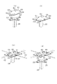
屋根構造物Yは、略直方体形状に形成された複数の屋根ユニット41,42が、横並びに設けられることによって構成されている。屋根ユニット41,42は、フレーム構造部分の他、断熱材や折板材43の下に設けられる防水材等を有してユニット化されているが、ここではフレーム構造部分を中心に説明することとし、図示もフレーム構造のみとする。この屋根ユニット41,42は、第1屋根ユニット41と、第2屋根ユニット42とよりなる。
The roof structure Y is configured by a plurality of
第1屋根ユニット41は、その長辺部同士を隣り合わせた状態で並べて設けられている。この実施の形態では、図2に示すように7つの第1屋根ユニット41が設けられている。その並べられた状態の各第1屋根ユニット41により、第1屋根ユニット構成部46が形成されている。第1屋根部31は、この第1屋根ユニット構成部46によって構成されている。
The
第2屋根ユニット42も、その長辺部同士を隣り合わせた状態で並べて設けられている。この実施の形態では、図2に示すように7つの第1屋根ユニット41が設けられている。その並べられた状態の各第2屋根ユニット42により、第2屋根ユニット構成部47が形成されている。第2屋根部32は、この第2屋根ユニット構成部47によって構成されている。
The
もっとも、第2屋根ユニット42に関しては、建物10の幅方向(屋根13の傾斜と直交する方向)の一端に設けられる一つの第2屋根ユニット42aは、その長手寸法が他の第2屋根ユニット42のそれよりも短く形成されている。このため、図1に示すように、この第2屋根ユニット42aが設けられた部分では、第2屋根部32が建物正面側から見て窪んだ状態となっている。
However, with respect to the
また、第1屋根ユニット41と第2屋根ユニット42とは、それぞれの長手方向が屋根13の傾斜方向に沿うようにして並べられている。これにより、両屋根ユニット41,42の長手方向の端面部分が互いに突き合わされ、その状態で、第1屋根ユニット41と第2屋根ユニット42とが連結されている。一つの第1屋根ユニット41と一つの第2屋根ユニット42とがこのように連結された状態のものを、一つの屋根ユニット体45とする。建物10の幅方向に沿って複数の屋根ユニット体45が並んで設けられた状態で一体化され、屋根13を構成する屋根構造物Yが形成されている。
Further, the
なお、建物10の幅方向において、長辺部同士を隣り合わせて並べて配置された7個の第1屋根ユニット41の合計長さ寸法と、同じく長辺部同士を隣り合わせて並べて配置された7個の第2屋根ユニット42の合計長さ寸法とは同じとなっている。各屋根ユニット41,42の短手寸法は、このように長さ寸法が同じとなるように設定されている。
In addition, in the width direction of the
図3に示すように、第1屋根ユニット41及び第2屋根ユニット42により構成された屋根構造物Yは、基礎11に立設されたラチス柱21及び間柱22の上端部に設けられた上梁23に設置されている。上梁23はH形鋼により形成されており、上下方向に延びるウェブと、ウェブの上下に配置された一対の水平なフランジとを有している。このフランジの上に屋根構造物Yが設置されている。上梁23は、図2(a)に示した外壁部17に沿って延びるように設けられている。
As shown in FIG. 3, the roof structure Y constituted by the
次に、このように上梁23に設置された屋根構造物Yの躯体構成について図4〜図7を参照しつつ説明する。図4は第1屋根ユニット41及び第2屋根ユニット42を示す斜視図であり、図5は第1屋根ユニット41と第2屋根ユニット42との連結部分を拡大して示す側面図である。また、図6は、隣り合う各屋根ユニット41,42の連結部分を示す概略斜視図である。
Next, the frame structure of the roof structure Y thus installed on the
図4に示すように、第1屋根ユニット41は、水平方向に延びる屋根トラス51,52を有するトラスユニットとされている。屋根トラス51,52は、平行弦トラスとされており、上下に対向配置された上弦材55及び下弦材56と、それら上弦材55及び下弦材56を連結する斜材57を有している。上弦材55、下弦材56及び斜材57は、それぞれ溝形鋼により形成されており、溝部の開放側を水平方向に向けて配置されている。
As shown in FIG. 4, the
屋根トラス51,52のうち、第1屋根ユニット41の長手方向に沿って延びる長辺屋根トラス51は一対をなし、互いに平行に向き合うように設けられている。長辺屋根トラス51の上弦材55は、屋根13の傾斜に合わせて傾斜している。第1屋根ユニット41の短手方向に沿って延びる短辺屋根トラス52は、一対の長辺屋根トラス51の間に架け渡された状態でそれら長辺屋根トラス51を連結している。短辺屋根トラス52は、第1屋根ユニット41の長手方向に所定間隔で複数設けられている。長辺屋根トラス51の下弦材56、短辺屋根トラス52の上弦材55及び下弦材56は水平方向に延びている。
Among the roof trusses 51 and 52, the long-side roof trusses 51 extending along the longitudinal direction of the
第1屋根ユニット41の四隅及び短辺屋根トラス52が設けられた部分には、それぞれ束材58が設けられている。四隅に設けられた各束材58は、長辺屋根トラス51において上弦材55と下弦材56とを連結している。束材58は、斜材57等と同様に鋼材としての溝形鋼によって形成されており、溝部の開放側を水平方向に向けて配置されている。第1屋根ユニット41では、屋根トラス51,52の上弦材55、下弦材56及び四隅に設けられた束材58により直方体形状の骨格(フレーム)が形成されている。
なお、斜材57及び束材58は、上弦材55及び下弦材56よりも屋根ユニット内側に配置されており、斜材57及び束材58の外側面が、上弦材55及び下弦材56の内側面に溶接等により固定されている。第2屋根ユニット42は、長手方向の長さが異なるだけで、その他の構成は第1屋根ユニット41と同じとなっている。
The
第1屋根ユニット41において、四隅に設けられた束材58のうち、第2屋根ユニット42が連結される側(建物正面側であって、図3ではその左側)に配置された一対の束材58aには、第1連結部材としての連結金具59がそれぞれ設けられている。
In the
図5に示すように、連結金具59は、コ字状をなす板材により形成されている。連結金具59は、束材58aが延びる方向に沿って当該束材58aに取り付けられた基部59aを有している。基部59aの両端部には、第2屋根ユニット42側に向けて水平方向に突出する取付片部59bが設けられている。この取付片部59bが第2屋根ユニット42の四隅に設けられた束材58のうち、第1屋根ユニット41と連結される側に配置された束材58bに取り付けられている。このようにして第1屋根ユニット41の各束材58aと、第2屋根ユニット42の各束材58bとが連結金具59によって連結され、長手方向に沿って並ぶ第1屋根ユニット41と第2屋根ユニット42とが、一つの屋根ユニット体45として一体化されている。
As shown in FIG. 5, the connection fitting 59 is formed of a U-shaped plate material. The connection fitting 59 has a base portion 59a attached to the
それに加え、隣り合う屋根ユニット体45について、第1屋根ユニット41及び第2屋根ユニット42の各角部が集まった部分に、第2連結部材としての連結プレート61が設けられている。各角部が集まった部分とは、図2(a)に示すように、第1屋根ユニット構成部46と第2屋根ユニット構成部47との境界線と、屋根ユニット体45同士の境界線とが交差する交差部分Cである。この交差部分Cのすべてに、図2(b)に示すように連結プレート61が設けられている。
In addition, a connecting
図6に示すように、この連結プレート61は各屋根ユニット41,42の下面側に当接した状態で設けられている。連結プレート61は、四角形状をなす板状に形成されている。連結プレート61は、その一対の辺において下方に延設されたフランジ62が設けられており、このフランジ62により連結プレート61の強度が補強されている。
As shown in FIG. 6, the connecting
連結プレート61の上面は、各屋根ユニット41,42の角部が載置される載置面63となっている。平面部としての載置面63は、図に一点鎖線により仮想的に示すように4つの載置領域S1〜S4に区分されている。各載置領域S1〜S4は、載置面63を4等分することにより形成され、各屋根ユニット41,42の角部が載置される領域となっている。
The upper surface of the connecting
第1載置領域S1及び第2載置領域S2は、屋根13の傾斜方向に並んで設けられ、第1屋根ユニット体45aを構成する屋根ユニット41,42の各角部がそれぞれ載置される。より詳しくは、図5に示すように、屋根ユニット41,42の各角部を形成する束材58a,58b、長辺屋根トラス51の下弦材56及び短辺屋根トラス52の下弦材56により角部が形成され、これら載置領域S1,S2に載置される。
The first placement area S1 and the second placement area S2 are provided side by side in the inclination direction of the
なお、束材58には、その下端に固定金物Kが設けられており、その固定金物Kを介して載置されている。このため、屋根ユニット41,42の角部が載置されるとしても、連結プレート61の載置面63に実際に当接しているのは、束材58a,58bの下端に設けられた固定金物Kとなる。
The
図6に戻って、第3載置領域S3及び第4載置領域S4は、屋根13の傾斜方向に並んで設けられ、第2屋根ユニット体45bを構成する屋根ユニット41,42の各角部がそれぞれ載置される。第2屋根ユニット体45bは、第1屋根ユニット体45aに隣接する屋根ユニット体45である。なお、図6では、第2屋根ユニット体45bの第2屋根ユニット42(第4載置領域S4に角部が載置されるもの)が省略されている。
Returning to FIG. 6, the third placement region S3 and the fourth placement region S4 are provided side by side in the inclination direction of the
載置面63の各載置領域S1〜S4には、それぞれ連結用孔64が設けられている。各屋根ユニット41,42の角部が載置面63に載置された状態で、図5に示すように、連結用孔64に挿通されたボルト65を用いて、連結プレート61に各屋根ユニット41,42の角部が連結される。より詳しくは、束材58の下端部に設けられた固定金物Kが載置面63に載置された状態で、固定金物Kと連結プレート61とがボルト65により連結される。
A connecting
以上のように、複数の第1屋根ユニット41と複数の第2屋根ユニット42とが一体化されて屋根構造物Yが形成され、前述したように、それが上梁23によって支持されている。その上梁23による支持に関し、図3に示すように、第1屋根ユニット41に設けられた四隅の束材58のうち、第2屋根ユニット42が連結される側とは反対側(建物奥側であって、図3の右側)に配置された一対の束材58cが上梁23に載置されている。この場合、束材58cには、その下端部に前記固定金物K(図5参照)と同様の固定金物(図示略)が設けられており、この固定金物(図示略)を介して上梁23のフランジに載置され、ボルト等の固定具を用いて固定されている。このようにして、屋根構造物Yのうち、建物奥行方向の一端側(建物奥側)が支持されている。
As described above, the plurality of
一方、建物奥行方向の建物正面側では、第2屋根ユニット42のうち、長辺屋根トラス51の長手方向中間部であって、短辺屋根トラス52が設けられた部分の束材58dが上梁23に載置されている。この束材58dも、その下端部に設けられた固定金物(図示略)を介して上梁23のフランジに載置され、ボルト等の固定具を用いて固定されている。このようにして、屋根構造物Yのうち、建物奥行方向の建物正面側が支持されている。
On the other hand, on the front side of the building in the building depth direction, the
このように建物正面側では、第2屋根ユニット42の長手方向中間部が上梁23によって支持される。そのため、図2(a)及び(b)に示すように、第2屋根ユニット42は、上梁23を支持する柱21,22を含んだ外壁部17よりも正面側に突出している。第2屋根ユニット42のこの突出部分が、建物10の庇部14となる。
Thus, on the front side of the building, the longitudinal intermediate portion of the
続いて、以上のように構成された建物10の屋根構造物Yについて、その屋根構造物Yを構築する構築手順について説明する。
Next, the construction procedure for constructing the roof structure Y of the
建築現場において基礎11を構築した後、工場から建築現場にラチス柱21や間柱22、上梁23などを運搬し、建築現場において建物本体12を構築する。そして、工場にて屋根ユニット41,42を予め製作しておき、屋根ユニット41,42をその工場から建築現場にトラック等にて運搬する。建築現場において屋根ユニット41,42を建物本体12の上に設置し、建物本体12に対して固定することで屋根13を構築する。なお、運搬に用いるトラックは10t車等の大型車両とすることが好ましい。
After constructing the
上記手順のうち、屋根ユニット41,42を連結して屋根構造物Yを設置する際の手順について、図7〜図9を参照しつつさらに説明する。図7は建物10を側面から見た状態において屋根構造物Yの構築手順を説明する説明図であり、図8は仮柱24を示す斜視図であり、図9は連結プレート61を取り付ける手順を説明する説明図である。図7及び図9の(a)〜(d)は、いずれも施工の段階を示している。図9における一点鎖線は、屋根ユニット41,42の角部を示している。
Among the above procedures, the procedure when the
図7(a)に示すように、屋根構造物Yを構築する前に、建物10の基礎11に、柱21,22を含む外壁部17を設置する。その柱21,22の上端部には、上梁23も設置する。これに加え、第1屋根ユニット構成部46と第2屋根ユニット構成部47との境界となる部分に、仮柱24を設置する。これにより、建物10の奥行方向に相対向する一対の外壁部17間、つまり平行な一対の上梁23(梁材)間に仮柱24が設けられる。この仮柱24は後に取り除かれるものであり、屋根構造物Yを構築する際に一時的に設置される。そのため、仮柱24は、ラチス柱21や間柱22とは異なり、基礎11に固定されていない。
As shown in FIG. 7A, before building the roof structure Y, the
図8に示すように、仮柱24は、第1柱部25と第2柱部26とを有している。第2柱部26は、第1柱部25と同じ軸線方向に延びて、当該第1柱部25の上に設けられている。第1柱部25と第2柱部26との間には、ネジ軸部27が設けられている。第1柱部25に取り付けられたハンドルHを回転させることによりネジ軸部27が回転し、それにともなって第2柱部26が上下方向に移動するように構成されている。この第2柱部26の移動により、仮柱24の高さが変更可能となる。
As shown in FIG. 8, the
第2柱部26の上端部には、十字状をなすプレート載置部28が設けられている。プレート載置部28の上面には、各端部に突起部29が設けられており、この突起部29を利用して、プレート載置部28に連結プレート61が載置される。図9(a)及び(b)に示すように、連結プレート61には、その四辺ごとの中央部に挿入孔66が設けられている。この挿入孔66に突起部29を挿入することで、プレート載置部28に載置された連結プレート61が、プレート載置部28から外れることを抑制している。
A
このように連結プレート61が上端部に設けられるとともに、屋根ユニット41,42の下端の高さに合わせて第2柱部26が上昇した状態となっている仮柱24が、図7(a)に示すように、基礎11に設置されている。仮柱24は複数本準備され、第1屋根ユニット構成部46と第2屋根ユニット構成部47との境界線と、屋根ユニット体45同士の境界線とが交差する交差部分C(図2(a)参照。)ごとに設置する。つまり、連結プレート61が設けられる部分ごとに仮柱24を設置する。
As shown in FIG. 7A, the connecting
図7(a)に示すように、仮柱24が設置された状態で、次に、第1屋根ユニット41を設置する。第1屋根ユニット41をその長手方向が建物10の幅方向と直交する方向に向くようにし、建物正面側となる第2屋根ユニット42との連結側の端部を、仮柱24の連結プレート61上に載置する。この場合、隣接する一対の仮柱24の連結プレート61間に、第1屋根ユニット41の短辺部分が架け渡されるように、その短手方向両端の角部を各連結プレート61に載置する。一方、建物奥側となる端部は、柱21,22の上端部に設けられた上梁23の上に載置する。そして、建物正面側では、ボルト65を用いて連結プレート61とそこに載置された角部(より詳しくは束材58a)とを連結し(図5参照)、建物裏側では上梁23と束材58bとを同じくボルト等を用いて連結する。
As shown in FIG. 7A, the
次いで、図7(b)に示すように、第2屋根ユニット42を設置する。第2屋根ユニット42をその長手方向が建物10の幅方向と直交する方向に向くようにし、建物正面側では、束材58dを上梁23の上に載置する。その反対側となる建物奥側(第1屋根ユニット41との連結側)は、仮柱24の連結プレート61上に載置する。この場合、隣接する一対の仮柱24の連結プレート61間に、第2屋根ユニット42の短辺部分が架け渡されるように、その短手方向両端の角部を各連結プレート61に載置する。そして、建物正面側では、上梁23と束材58dとをボルト等で連結し、その反対の裏側では、連結金具59により第1屋根ユニット41と連結する。また、ボルト65を用いて連結プレート61とそこに載置された角部(より詳しくは束材58b)とを連結する(図5参照)。
Next, as shown in FIG. 7B, the
これにより、図7(c)に示すように、第1屋根ユニット41と第2屋根ユニット42とは、その短辺部同士が互いに連結される。このようにして建物10の幅方向に各屋根ユニット41,42を順次設置する。その結果、図9(c)に示すように、屋根ユニット41,42の境界線が交差する交差部分Cにおいて、隣接する屋根ユニット41,42の各角部が連結プレート61によって連結される。なお、それら各角部は、仮柱24によって支持される被支持部に相当する。
Thereby, as shown in FIG.7 (c), as for the
続いて、図8(b)に示すように、ハンドルHを回転させて第2柱部26の位置を下げ、仮柱24の高さを低くする。これにより、図9(d)に示すように、屋根ユニット41,42に連結された連結プレート61を残し、プレート載置部28が連結プレート61から外れる。その後、図7(d)に示すように、基礎11に設置していた仮柱24を取り外せば、屋根ユニット41,42によって構築された屋根構造物Yが得られる。
Subsequently, as shown in FIG. 8B, the handle H is rotated to lower the position of the
以上詳述した本実施形態によれば、以下の優れた効果が得られる。 According to the embodiment described in detail above, the following excellent effects can be obtained.
まず、上記の屋根構造物Yに関し、第1屋根ユニット41と第2屋根ユニット42との境界線と、屋根ユニット体45同士の境界線との交差部分Cのすべてに、連結プレート61が設けられている。そのため、第1屋根ユニット41と第2屋根ユニット42とが連結金具59によって連結されて屋根ユニット体45が構成されることに加え、連結プレート61により、交差部分Cにおいて互いに隣接し合う各屋根ユニット41,42の角部が連結される。これにより、屋根構造全体の強度が補強されることとなり、第1屋根ユニット構成部46と第2屋根ユニット構成部47との境界上に柱等を設け、その柱等によって境界部分を支える必要がなくなる。その結果、トラック等による輸送時の輸送制限を遵守しつつ、第1屋根ユニット41の長手方向に沿った奥行寸法が長くなった、より広い建物10の屋内空間16を確保することができる。
First, with respect to the roof structure Y described above, the
上記の屋根構造物Yでは、第1屋根ユニット41が、その長辺部同士を隣り合わせて並べて設けられるとともに、第2屋根ユニット42も、その長辺部同士を隣り合わせて並べて設けられている。そして、第1屋根ユニット41と第2屋根ユニット42とは、その短辺部同士が互いに連結され、屋根ユニット体45が構成されている。これにより、建物10の奥行寸法は、第1屋根ユニット41の長手寸法に加え、第2屋根ユニット42の長手寸法を合わせた長さを有することとなり、より一層広い屋内空間16を得ることができる。この場合、第2屋根ユニット42の長手方向の長さを、輸送制限の範囲内で任意に設定することができるため、所望の奥行寸法を有する屋内空間16を得ることができる。
In the roof structure Y described above, the
上記の屋根構造物Yの屋根面は、建物正面側から裏側にかけて傾斜する片流れとなっている。そして、第2屋根ユニット42は第1屋根ユニット41の傾斜上部側、つまり、第1屋根ユニット41において高さ寸法がもっとも高い側に設けられている。一方、第1屋根ユニット41の傾斜下部側、つまり第1屋根ユニット41において高さ寸法がもっとも低い側が上梁23に載置され、外壁部17によって支持されている。このため、第1屋根ユニット41では、その高さ寸法が低くて比較的強度の弱い側が外壁部17によって支持される一方、高さ寸法が高く強度を確保できる側で、第2屋根ユニット42と連結され、連結プレート61を用いた屋根ユニット41,42同士の連結がなされている。片流れの傾斜において、第1屋根ユニット41の傾斜下部側に、より高さ寸法を低くする第2屋根ユニット42を設けた構成では、両屋根ユニット41,42を連結する部分での強度を確保しづらいのに対し、上記の構成によれば十分な強度を確保できる。
The roof surface of the roof structure Y is a single stream that is inclined from the front side to the back side of the building. The
境界線の交差部分Cに設けられた連結プレート61は、第1屋根ユニット41及び第2屋根ユニット42に対し、その下側から装着されてそれらと連結されている。このため、トラス構造内で連結する構成に比べ、連結プレート61を設置する作業が容易となる。特に、交差部分Cを仮柱24で支えつつ屋根構造物Yを構築する場合には、その仮柱24の上端部に連結プレート61を設置して、連結プレート61の載置面63に各屋根ユニット41,42の角部が載置する。その状態で、連結プレート61と各屋根ユニット41,42とを連結するという手法を採用できる。これにより、連結プレート61と各屋根ユニット41,42との連結作業を行いやすい。
The connecting
また、屋根構造物Yを構築する上記の施工方法に関して、交差部分Cのすべてにまず仮柱24が設けられる。この仮柱24により、第1屋根ユニット41及び第2屋根ユニット42がそれぞれ一時的に支持され、その状態で、連結金具59や連結プレート61を用いた屋根ユニット41,42間の連結が行われる。仮柱24は、その連結後に外される。これにより、第1屋根ユニット構成部46と第2屋根ユニット構成部47との境界部分に柱や内壁部のない屋根構造物Yを好適に構築することができる。
Moreover, regarding the construction method for constructing the roof structure Y, the
この場合に、連結プレート61は、その挿入孔66に、仮柱24の上端部に設けられた突起部29が挿入されただけの状態で、仮柱24に対して着脱自在に設けられている。その連結プレート61の上に、屋根ユニット41,42の各角部が載置される。それら各角部が連結プレート61に載置された状態で、連結プレート61と各角部とが連結されるため、連結作業が行いやすい。
In this case, the connecting
また、仮柱24は第1柱部25と第2柱部26戸を有し、第2柱部26を上下に移動させて、仮柱24の高さを変更することが可能な構成となっている。そのため、仮柱24の高さ寸法を高い状態に設定し、その連結プレート61の載置面63に屋根ユニット41,42の各角部を載置してそれらを連結した後に、仮柱24の高さを低くすれば、各角部に連結された連結プレート61が残って仮柱24から外れる。これにより、高さが低くなってすでに屋根ユニット41,42を支持する状態ではなくなった仮柱24を容易に取り外すことができ、屋根構造物Yの構築を容易に行うことができる。
Moreover, the
[他の実施形態]
本発明は、上記実施の形態で説明した内容に限定されるものではなく、例えば次のように実施されてもよい。
[Other Embodiments]
The present invention is not limited to the contents described in the above embodiment, and may be implemented as follows, for example.
(1)上記実施の形態では、第1屋根ユニット41と第2屋根ユニット42とは、それぞれの短辺部同士をつなぎ合わせた状態で並べたが、第2屋根ユニット42をその長手方向が各第1屋根ユニット41の並び方向と平行になる向きで配置してもよい。図10に、その一例を示す。
(1) In the said embodiment, although the
この場合、第2屋根ユニット42は、第1屋根ユニット41同士の境界部を跨いだ状態となり、第1屋根ユニット41の長手方向と第2屋根ユニット42の長手方向とは直交する。そして、第2屋根ユニット42は、その短辺部分が、第1屋根ユニット41の傾斜方向に沿って傾斜するように形成されている。
In this case, the
そして、第1屋根ユニット41同士の境界線と、第1屋根ユニット構成部46と第2屋根ユニット構成部47との境界線とが交差する部分のすべてに、連結プレート61が設けられる。その連結プレート61が設けられた部分において互いに隣接し合う第1屋根ユニット41及び第2屋根ユニット42が、その連結プレート61と連結される。
And the
また、第1屋根ユニット41の並び方向についても、上記実施の形態では建物10の幅方向を並び方向としたが、建物10の奥行方向を並び方向としてもよい。
Also, regarding the arrangement direction of the
(2)上記実施の形態では、屋根13を建物正面側から建物奥側にかけて傾斜する片流れの傾斜屋根としたが、屋根13の傾斜はこれと異なっていてもよい。例えば、図11(a)に示すように、切妻の傾斜屋根としてもよい。この場合、第2屋根ユニット42では、建物正面側の端部が屋根面の下端とされ、第1屋根ユニット41との境界側の端部が屋根面の上端とされている。
(2) In the above embodiment, the
また、図11(b)に示すように、片流れの傾斜方向を逆とし、建物奥側から建物正面側に向けて片流れとなる傾斜屋根としたり、第1屋根部31と第2屋根部32との境界部分の段差をなくし、連続して傾斜する構成を採用したりしてもよい。
Moreover, as shown in FIG.11 (b), it is set as the inclined roof which reverses the inclination direction of a single flow, and becomes a single flow toward the building front side from the building back side, or the
(3)上記実施の形態では、相対的に長手寸法が長い第1屋根ユニット41が建物奥側に、第2屋根ユニット42が建物正面側に設けられているが、上記図11(b)に示すように、これとは前後を逆にしてもよい。この場合、第1屋根ユニット41が建物正面側に、第2屋根ユニット42が建物奥側に設けられる。
(3) In the above embodiment, the
(4)上記実施の形態では、屋根13を傾斜屋根としたが、その傾斜勾配を小さくして水勾配のレベルとし、そのような水勾配が設けられた陸屋根(フラットルーフ)としてもよい。
(4) In the above-described embodiment, the
(5)上記実施の形態では、第1連結部材の例としてコ字状をなす連結金具59を用いたが、四角形状をなすものなど、他の構成を採用してもよい。また、第2連結部材の例として連結プレート61を用いたが、連結プレート61に代えて別の構成を採用してもよい。例えば、連結プレート61が設けられた交差部分Cに集まった4つの束材58の周囲を取り囲む連結用の金物を設け、それら各束材58をそれぞれ連結用の金物に固定することで一体化するようにしてもよい。
(5) In the above-described embodiment, the U-shaped connection fitting 59 is used as an example of the first connection member, but other configurations such as a rectangular shape may be adopted. Further, although the
(6)上記実施の形態では、各屋根ユニット41,42は屋根トラス51,52を有する構成としたが、屋根トラス51,52を有していない構成としてもよい。例えば、十分な強度を有する梁材を設けた構成とすれば、屋根トラス51,52に代わる強度を確保することができる。また、各屋根ユニット41,42に設けられる折板材43は、建築現場で取り付けられるようにしてもよいし、ユニットとして工場で予め取り付けられた状態としてもよい。
(6) Although the
このように屋根トラス51,52を有しない構成とした場合、連結プレート61の載置面63には、屋根ユニット41,42の角部を構成し、束材51a,58bに代わる柱状部が少なくとも載置されることになる。この柱状部の下端にも、束材51a,58bと同様、固定金物Kが設けられることが好ましい。
Thus, when it is set as the structure which does not have the roof trusses 51 and 52, the mounting
(7)上記実施の形態では、第2屋根ユニット42の長手寸法を第1屋根ユニット41のそれよりも短くしたが、第1屋根ユニット41と同じ長手寸法としてもよい。この場合でも、各屋根ユニット41,42の長手寸法は、輸送制限の範囲内に設定することが好ましい。
(7) Although the longitudinal dimension of the
(8)上記実施の形態では、屋内空間16に柱や内壁部等が全く存在しない場合を例として説明したため、屋根構造物Yには、交差部分Cのすべてに連結プレート61が設けられている。建物10の間取りによっては、第1屋根ユニット構成部46と第2屋根ユニット構成部47との境界線上の一部に、柱や内壁部を設けてもよい。この場合、連結プレート61は、その柱や内壁部による支えのない交差部分Cにのみ設ければ足りる。屋根構造物Yの施工時に仮柱24が設置されるのも、その部分のみとなる。
(8) In the above embodiment, the case where no pillars or inner walls exist in the
(9)上記実施の形態では、屋根構造物Yを構築する手順として、第1屋根ユニット41を設置した後に、第2屋根ユニット42を連結し、さらにその後、建物10の幅方向に各屋根ユニット41,42を順次設置する方法を示した。これに代えて、第2屋根ユニット42を第1屋根ユニット41よりも先に設置してもよいし、複数の第1屋根ユニット41のみをすべて設置した後に、複数の第2屋根ユニット42を順次設置する手順又はその逆の手順を採用してもよい。
(9) In the above embodiment, as a procedure for constructing the roof structure Y, after installing the
(10)上記実施の形態では、コンビニエンスストアの店舗として使用される建物10に具体化したものとして説明したが、建物10は、スーパー、商店、事務所等の他の用途に利用してもよい。
(10) Although the above embodiment has been described as being embodied in the
10…建物、21,22…柱、23…上梁(梁材)、24…仮柱、41…第1屋根ユニット、42…第2屋根ユニット、46…第1屋根ユニット構成部、47…第2屋根ユニット構成部、59…連結金具(第1連結部材)、61…連結プレート(第2連結部材)、63…載置部(平面部)、C…交差部分。
DESCRIPTION OF
Claims (7)
長辺部同士を隣り合わせて並べて設けられた前記複数の第1屋根ユニットよりなる第1屋根ユニット構成部と、
前記複数の第1屋根ユニットと同じ方向に並べて設けられた前記複数の第2屋根ユニットよりなる第2屋根ユニット構成部と、
隣接する前記第1屋根ユニットと前記第2屋根ユニットとを連結する第1連結部材と、
前記第1屋根ユニット同士の境界線と、前記第1屋根ユニット構成部及び前記第2屋根ユニット構成部の境界線とが交差する交差部分に設けられ、当該交差部分で互いに隣接し合う前記第1屋根ユニット及び前記第2屋根ユニット同士を連結する第2連結部材と、
を有することを特徴とする建物の屋根構造。 A plurality of roof units having a substantially rectangular parallelepiped shape are provided side by side, and the plurality of roof units are a roof structure of a building including a plurality of first roof units and a plurality of second roof units,
A first roof unit constituent part composed of the plurality of first roof units provided side by side along the long sides; and
A second roof unit component comprising the plurality of second roof units provided side by side in the same direction as the plurality of first roof units;
A first connecting member that connects the adjacent first roof unit and the second roof unit;
The first roof unit is provided at an intersection where the boundary line between the first roof units intersects with the boundary line between the first roof unit component and the second roof unit component, and is adjacent to each other at the intersection. A second connecting member that connects the roof unit and the second roof unit;
The roof structure of the building characterized by having.
前記第1屋根ユニットと前記第2屋根ユニットとは短辺部同士が互いに連結され、
前記交差部分では、前記第1屋根ユニット及び前記第2屋根ユニットの各角部が前記第2連結部材に連結されていることを特徴とする請求項1に記載の建物の屋根構造。 The second roof unit is provided side by side with the long sides next to each other,
Short sides of the first roof unit and the second roof unit are connected to each other,
2. The building roof structure according to claim 1, wherein each of the corners of the first roof unit and the second roof unit is connected to the second connecting member at the intersection.
前記第1屋根ユニットの傾斜上部側に前記第2屋根ユニットが設けられ、
前記第1屋根ユニットの傾斜下部側が柱によって支持されていることを特徴とする請求項2に記載の建物の屋根構造。 The first roof unit has a slope that is inclined along its longitudinal direction,
The second roof unit is provided on the inclined upper side of the first roof unit,
The building roof structure according to claim 2, wherein the inclined lower side of the first roof unit is supported by a pillar.
前記複数の第1屋根ユニットと同じ方向に並べて設けられた複数の第2屋根ユニットよりなる第2屋根ユニット構成部と、
隣接する前記第1屋根ユニットと前記第2屋根ユニットとを連結する第1連結部材と、
を有する屋根構造物の施工方法であって、
前記第1屋根ユニットの長手方向に相対向する一対の平行な梁材間で、前記第1屋根ユニット同士の境界線と、前記第1屋根ユニット構成部及び前記第2屋根ユニット構成部の境界線とが交差する交差部分に仮柱を設置し、
一対の前記梁材のうちの一方と前記仮柱とで、前記第1屋根ユニットの長手方向両端部を支持し、
一対の前記梁材のうちの他方と前記仮柱とで、前記第2屋根ユニットを支持し、
前記仮柱で支持された状態にある前記第1屋根ユニットと前記第2屋根ユニットとを第1連結部材によって連結するとともに、前記交差部分で互いに隣接し合う前記第1屋根ユニット及び前記第2屋根ユニット同士を第2連結部材によって連結し、
その後、前記仮柱を外すようにしたことを特徴とする屋根構造物の施工方法。 A substantially rectangular parallelepiped shape, and a first roof unit constituent part composed of a plurality of first roof units provided side by side with long sides thereof,
A second roof unit component comprising a plurality of second roof units arranged side by side in the same direction as the plurality of first roof units;
A first connecting member that connects the adjacent first roof unit and the second roof unit;
A construction method of a roof structure having
Between a pair of parallel beams facing each other in the longitudinal direction of the first roof unit, a boundary line between the first roof units, and a boundary line between the first roof unit constituent part and the second roof unit constituent part Install a temporary pillar at the intersection where
With one of the pair of beam members and the temporary column, supporting both longitudinal ends of the first roof unit,
The second roof unit is supported by the other of the pair of beam members and the temporary column,
The first roof unit and the second roof unit, which are supported by the temporary pillars, are connected by a first connecting member, and are adjacent to each other at the intersection. Units are connected by a second connecting member,
Then, the construction method of the roof structure characterized by removing the said temporary pillar.
前記仮柱には、その上端部に前記連結プレートがその平面を水平にして着脱自在に設けられており、
前記仮柱によって支持される前記第1屋根ユニット及び前記屋根ユニットのそれぞれの被支持部は、前記連結プレートの上に載置され、
前記連結プレートと前記被支持部とを連結し、その後に、前記連結プレートを残して前記仮柱から外すようにしたことを特徴とする請求項5に記載の屋根構造物の施工方法。 The second connecting member is a connecting plate having a plate shape,
In the temporary column, the connecting plate is provided at its upper end portion so as to be detachable with its flat surface horizontal,
Each supported portion of the first roof unit and the roof unit supported by the temporary column is placed on the connection plate,
6. The method for constructing a roof structure according to claim 5, wherein the connecting plate and the supported portion are connected, and thereafter, the connecting plate is left and removed from the temporary pillar.
前記連結プレートを前記第1屋根ユニット及び前記第2屋根ユニットの下面側に連結した後に、前記仮柱の高さを低くすることにより前記連結プレートを前記仮柱から外すようにしたことを特徴とする請求項6に記載の屋根構造物の施工方法。 The temporary pillar is configured such that its height can be changed,
After connecting the connection plate to the lower surface side of the first roof unit and the second roof unit, the connection plate is removed from the temporary column by lowering the height of the temporary column. The construction method of the roof structure of Claim 6.
Priority Applications (1)
| Application Number | Priority Date | Filing Date | Title |
|---|---|---|---|
| JP2015119636A JP6465758B2 (en) | 2015-06-12 | 2015-06-12 | Construction method of roof structure |
Applications Claiming Priority (1)
| Application Number | Priority Date | Filing Date | Title |
|---|---|---|---|
| JP2015119636A JP6465758B2 (en) | 2015-06-12 | 2015-06-12 | Construction method of roof structure |
Publications (2)
| Publication Number | Publication Date |
|---|---|
| JP2017002642A true JP2017002642A (en) | 2017-01-05 |
| JP6465758B2 JP6465758B2 (en) | 2019-02-06 |
Family
ID=57751729
Family Applications (1)
| Application Number | Title | Priority Date | Filing Date |
|---|---|---|---|
| JP2015119636A Expired - Fee Related JP6465758B2 (en) | 2015-06-12 | 2015-06-12 | Construction method of roof structure |
Country Status (1)
| Country | Link |
|---|---|
| JP (1) | JP6465758B2 (en) |
Cited By (1)
| Publication number | Priority date | Publication date | Assignee | Title |
|---|---|---|---|---|
| JP6433107B1 (en) * | 2017-11-13 | 2018-12-05 | 株式会社エスビーエル | Building structure, building and construction method |
Citations (8)
| Publication number | Priority date | Publication date | Assignee | Title |
|---|---|---|---|---|
| JPH06108575A (en) * | 1992-09-30 | 1994-04-19 | Misawa Homes Co Ltd | Mansard roof structure and construction thereof |
| JPH06185120A (en) * | 1992-12-18 | 1994-07-05 | Haseko Corp | Construction method for upper structure of roof, etc. |
| JPH10252141A (en) * | 1997-03-17 | 1998-09-22 | Tomoe Corp | Joint construction for truss structure |
| JP2000087455A (en) * | 1998-09-09 | 2000-03-28 | Sekisui Chem Co Ltd | Temporary column structure, building unit and execution method for unit building |
| JP2001214529A (en) * | 2000-02-03 | 2001-08-10 | Misawa Homes Co Ltd | Reinforcing plate and unit type building |
| JP2003160974A (en) * | 2002-10-15 | 2003-06-06 | Misawa Homes Co Ltd | Unit type building and its building method |
| JP2005282038A (en) * | 2004-03-29 | 2005-10-13 | Daiwa Kosho Lease Co Ltd | Unit type business facility building |
| JP2014105458A (en) * | 2012-11-27 | 2014-06-09 | Toyota Home Kk | Roof structure of building |
-
2015
- 2015-06-12 JP JP2015119636A patent/JP6465758B2/en not_active Expired - Fee Related
Patent Citations (8)
| Publication number | Priority date | Publication date | Assignee | Title |
|---|---|---|---|---|
| JPH06108575A (en) * | 1992-09-30 | 1994-04-19 | Misawa Homes Co Ltd | Mansard roof structure and construction thereof |
| JPH06185120A (en) * | 1992-12-18 | 1994-07-05 | Haseko Corp | Construction method for upper structure of roof, etc. |
| JPH10252141A (en) * | 1997-03-17 | 1998-09-22 | Tomoe Corp | Joint construction for truss structure |
| JP2000087455A (en) * | 1998-09-09 | 2000-03-28 | Sekisui Chem Co Ltd | Temporary column structure, building unit and execution method for unit building |
| JP2001214529A (en) * | 2000-02-03 | 2001-08-10 | Misawa Homes Co Ltd | Reinforcing plate and unit type building |
| JP2003160974A (en) * | 2002-10-15 | 2003-06-06 | Misawa Homes Co Ltd | Unit type building and its building method |
| JP2005282038A (en) * | 2004-03-29 | 2005-10-13 | Daiwa Kosho Lease Co Ltd | Unit type business facility building |
| JP2014105458A (en) * | 2012-11-27 | 2014-06-09 | Toyota Home Kk | Roof structure of building |
Cited By (2)
| Publication number | Priority date | Publication date | Assignee | Title |
|---|---|---|---|---|
| JP6433107B1 (en) * | 2017-11-13 | 2018-12-05 | 株式会社エスビーエル | Building structure, building and construction method |
| WO2019092882A1 (en) * | 2017-11-13 | 2019-05-16 | 株式会社エスビーエル | Building structure, building, and building method |
Also Published As
| Publication number | Publication date |
|---|---|
| JP6465758B2 (en) | 2019-02-06 |
Similar Documents
| Publication | Publication Date | Title |
|---|---|---|
| JP2011202439A (en) | Building unit | |
| JP6465758B2 (en) | Construction method of roof structure | |
| JP2866993B2 (en) | Prefabricated building | |
| JP5128313B2 (en) | Unit building | |
| JPH08177127A (en) | Unit building | |
| JP2007262725A (en) | Unit building | |
| JP3831545B2 (en) | Unit building | |
| JP3236094B2 (en) | Unit building | |
| JP2007170085A (en) | Omitted column unit garage | |
| JP4449928B2 (en) | Unit building | |
| JPH1061025A (en) | Unit building and construction method thereof | |
| JP5301700B1 (en) | Attached units and unit buildings | |
| JP4134941B2 (en) | Unit building and construction method thereof | |
| JP7299797B2 (en) | modular building | |
| JPH05140993A (en) | Structure of medium/high multistorey building | |
| JP3574625B2 (en) | Unit building and its construction method | |
| JP3429629B2 (en) | Unit building and its construction method | |
| JP4449886B2 (en) | Unit building | |
| JP2661302B2 (en) | Grating floor construction method | |
| JP4205884B2 (en) | Unit building | |
| JP2023066261A (en) | building | |
| JP2006009359A (en) | Three-dimensional structure | |
| JP2003049501A (en) | Bearing wall structure by steel-framed unit | |
| JP4302570B2 (en) | Unit building frame structure | |
| JP2007231623A (en) | Unit building |
Legal Events
| Date | Code | Title | Description |
|---|---|---|---|
| A621 | Written request for application examination |
Free format text: JAPANESE INTERMEDIATE CODE: A621 Effective date: 20170914 |
|
| A977 | Report on retrieval |
Free format text: JAPANESE INTERMEDIATE CODE: A971007 Effective date: 20180613 |
|
| A131 | Notification of reasons for refusal |
Free format text: JAPANESE INTERMEDIATE CODE: A131 Effective date: 20180619 |
|
| A521 | Request for written amendment filed |
Free format text: JAPANESE INTERMEDIATE CODE: A523 Effective date: 20180711 |
|
| TRDD | Decision of grant or rejection written | ||
| A01 | Written decision to grant a patent or to grant a registration (utility model) |
Free format text: JAPANESE INTERMEDIATE CODE: A01 Effective date: 20181218 |
|
| A61 | First payment of annual fees (during grant procedure) |
Free format text: JAPANESE INTERMEDIATE CODE: A61 Effective date: 20190108 |
|
| R150 | Certificate of patent or registration of utility model |
Ref document number: 6465758 Country of ref document: JP Free format text: JAPANESE INTERMEDIATE CODE: R150 |
|
| LAPS | Cancellation because of no payment of annual fees |