JP2017001902A - Cover glass and portable information terminal having the same, and method for producing cover glass - Google Patents

Cover glass and portable information terminal having the same, and method for producing cover glass Download PDF

Info

Publication number
JP2017001902A
JP2017001902A JP2015115139A JP2015115139A JP2017001902A JP 2017001902 A JP2017001902 A JP 2017001902A JP 2015115139 A JP2015115139 A JP 2015115139A JP 2015115139 A JP2015115139 A JP 2015115139A JP 2017001902 A JP2017001902 A JP 2017001902A
Authority
JP
Japan
Prior art keywords
cover glass
film
thin
thin portion
glass
Prior art date
Legal status (The legal status is an assumption and is not a legal conclusion. Google has not performed a legal analysis and makes no representation as to the accuracy of the status listed.)
Pending
Application number
JP2015115139A
Other languages
Japanese (ja)
Inventor
林 英明
Hideaki Hayashi
英明 林
茂輝 澤村
Shigeki Sawamura
茂輝 澤村
木原 直人
Naoto Kihara
直人 木原
浩司 中川
Koji Nakagawa
浩司 中川
諭 金杉
Satoshi Kanasugi
諭 金杉
智晴 長谷川
Tomoharu Hasegawa
智晴 長谷川
Current Assignee (The listed assignees may be inaccurate. Google has not performed a legal analysis and makes no representation or warranty as to the accuracy of the list.)
AGC Inc
Original Assignee
Asahi Glass Co Ltd
Priority date (The priority date is an assumption and is not a legal conclusion. Google has not performed a legal analysis and makes no representation as to the accuracy of the date listed.)
Filing date
Publication date
Application filed by Asahi Glass Co Ltd filed Critical Asahi Glass Co Ltd
Priority to JP2015115139A priority Critical patent/JP2017001902A/en
Publication of JP2017001902A publication Critical patent/JP2017001902A/en
Pending legal-status Critical Current

Links

Images

Abstract

PROBLEM TO BE SOLVED: To provide a cover glass which can reduce the warpage of a thin part and a portable information terminal having the same, and a method for producing a cover glass.SOLUTION: A cover glass 1 comprises at least one thin part 13 formed by providing at least one recess 7 on a surface 3 or a rear surface 5 of the cover glass 1, and a thick part 17 connected to the thin part 13. At least one of the surface 3 and the rear surface 5 of the thin part 13 has a film 21, 22 of 10-1000 nm formed thereon.SELECTED DRAWING: Figure 3

Description

本発明は、カバーガラス及びこれを有する携帯情報端末、並びにカバーガラスの製造方法に関する。   The present invention relates to a cover glass, a portable information terminal having the cover glass, and a method for manufacturing the cover glass.

近年、電子機器類における高度なセキュリティ対策として、指紋を個人の認証に用いる方法が盛んに用いられている。指紋認証の方法には、光学方式、感熱方式、圧力方式、静電容量方式などがあるが、センシング感度や消費電力の観点から静電容量方式が優れているとされている。   In recent years, a method of using a fingerprint for personal authentication is actively used as an advanced security measure in electronic devices. Fingerprint authentication methods include an optical method, a thermal method, a pressure method, and a capacitance method, and the capacitance method is considered to be superior from the viewpoint of sensing sensitivity and power consumption.

静電容量方式センサは、被検出物が接近、または、接触した部位の局所的な静電容量の変化を検出する。一般的な静電容量方式のセンサ(以下、単にセンサとも呼ぶ)は、該センサ内に配置された電極と被検出物との距離を静電容量の大きさによって測定する。このような静電容量方式センサを用いた指紋認証機能は、小型軽量で消費電力が低いことから、特にスマートフォンや携帯電話、タブレット型パーソナルコンピューターなどの携帯情報端末(Personal Data Assistance:PDA)に搭載されている。   The capacitance type sensor detects a local change in capacitance at a site where the detection object approaches or comes into contact. A general electrostatic capacity type sensor (hereinafter also simply referred to as a sensor) measures the distance between an electrode arranged in the sensor and an object to be detected based on the magnitude of the electrostatic capacity. Since the fingerprint authentication function using such a capacitance type sensor is small and light and has low power consumption, it is particularly mounted on personal information terminals (PDAs) such as smartphones, mobile phones, and tablet personal computers. Has been.

通常、静電容量方式センサを保護するため、該センサの上部には保護カバー(センサカバー)が配置される。例えば、特許文献1の静電容量方式センサパッケージングでは、センサが対象物を検出可能となるようにカバーガラスに孔を設け、当該孔にセンサカバーを配置することが開示されている。なお、センサカバーとしては、センシング感度を向上させるために誘電率が高く、厚みの小さい材料が使用される。また、カバーガラスとしては、電子機器の落下や他の物体との衝突に対する耐久性を確保するため、ガラスを化学強化したものが一般的に使用されている。   Usually, in order to protect a capacitive sensor, a protective cover (sensor cover) is disposed above the sensor. For example, in the capacitive sensor packaging of Patent Document 1, it is disclosed that a hole is provided in a cover glass so that the sensor can detect an object, and a sensor cover is disposed in the hole. As the sensor cover, a material having a high dielectric constant and a small thickness is used in order to improve sensing sensitivity. Moreover, as a cover glass, in order to ensure the durability with respect to the fall of an electronic device or a collision with another object, what strengthened the glass chemically is generally used.

特許文献1に記載された発明のように、カバーガラスに孔を設け、当該孔にセンサカバーを配置する構成では、センサカバーを孔に固定する治具等が必要となるため、部品点数が多くなり、組立工程も複雑化してしまう。また、カバーガラスの他にセンサカバー等の異種材料が必要となるため、材料的な統一感を実現することが困難であり、意匠性に劣っていた。   In the configuration in which a hole is formed in the cover glass and the sensor cover is disposed in the hole as in the invention described in Patent Document 1, a jig or the like for fixing the sensor cover to the hole is required, and thus the number of parts is large. This complicates the assembly process. Further, since a different material such as a sensor cover is required in addition to the cover glass, it is difficult to achieve a material sense of unity and the design is inferior.

国際公開第2013/173773号International Publication No. 2013/173773

そこで、本発明者らは、センサカバー等の異種材料を併用することなく、材料的に一様で統一感のある意匠性に優れたカバーガラスを想到した。すなわち、本発明者らは、カバーガラスの表面又は裏面に少なくとも一つの凹部が設けられることにより形成された少なくとも一つの薄肉部と、薄肉部に接続する厚肉部と、を備えるカバーガラスを想到した。このカバーガラスによれば、凹部に対応する位置にセンサを配置すれば、薄肉部によって当該センサを保護できる。   Therefore, the present inventors have come up with a cover glass that is uniform in material and has a sense of unity and is excellent in design without using different materials such as a sensor cover. That is, the present inventors have conceived a cover glass comprising at least one thin part formed by providing at least one concave part on the front or back surface of the cover glass, and a thick part connected to the thin part. did. According to this cover glass, if the sensor is arranged at a position corresponding to the concave portion, the sensor can be protected by the thin portion.

さらに、本発明者らは、薄肉部と、当該薄肉部に接続する厚肉部と、を備えるカバーガラスを化学強化した場合、薄肉部が表側又は裏側に反ることを見出した。これは、(イオン交換層の厚み/非イオン交換層の厚み)が、薄肉部と厚肉部とで異なることが原因であると考えられる。すなわち、薄肉部における(イオン交換層の厚み/非イオン交換層の厚み)が、厚肉部における(イオン交換層の厚み/非イオン交換層の厚み)よりも大きいため、化学強化時に薄肉部が厚肉部よりも膨張する。そして、薄肉部はその周縁を厚肉部によって規制された状態で膨張することになるため、表側又は裏側に反る。   Furthermore, the present inventors have found that when a cover glass including a thin part and a thick part connected to the thin part is chemically strengthened, the thin part warps on the front side or the back side. This is considered to be because (thickness of the ion exchange layer / thickness of the non-ion exchange layer) is different between the thin portion and the thick portion. That is, since (thickness of ion exchange layer / thickness of non-ion exchange layer) in the thin-walled portion is larger than (thickness of ion-exchange layer / thickness of non-ion-exchange layer) in the thick-walled portion, It expands more than the thick part. And since the thin part expand | swells in the state in which the periphery was regulated by the thick part, it will warp the front side or the back side.

本発明は、前述した課題に鑑みてなされたものであり、その目的は、薄肉部の反りを低減可能なカバーガラス、及びこれを有する携帯情報端末、並びにカバーガラスの製造方法を提供することにある。   This invention is made | formed in view of the subject mentioned above, The objective is to provide the manufacturing method of the cover glass which can reduce the curvature of a thin part, a portable information terminal which has this, and a cover glass. is there.

本発明の上記目的は、下記構成により達成される。
(1) 保護対象を保護するカバーガラスであって、
前記カバーガラスは、該カバーガラスの表面又は裏面に少なくとも一つの凹部が設けられることにより形成された少なくとも一つの薄肉部と、前記薄肉部に接続する厚肉部と、を備え、
前記薄肉部の表面及び裏面のうち少なくとも一方には、10〜1000nmの膜が形成される、カバーガラス。
(2) 前記膜の形成された部位の表面圧縮応力(CS)が、前記厚肉部に形成された圧縮応力層の表面圧縮応力に比べて小さくなる、(1)に記載のカバーガラス。
(3) 前記膜の主成分は酸化物である、(1)又は(2)に記載のカバーガラス。
(4) 前記酸化物がSiOである、(3)に記載のカバーガラス。
(5) 前記カバーガラスの表面又は裏面に前記凹部が一つ設けられることにより、前記カバーガラスには前記薄肉部が一つ形成され、
前記薄肉部の厚み及び面積をそれぞれt1及びs1とし、
前記厚肉部の厚み及び面積をそれぞれt2及びs2としたとき、
0.05≦t1/t2≦0.9、且つ0.001≦s1/s2≦0.9である、(1)〜(4)の何れか1つに記載のカバーガラス。
(6) (1)〜(5)の何れか1つに記載のカバーガラスを有する携帯情報端末。
(7) ガラス部材を化学強化することで保護対象を保護するカバーガラスを製造する、カバーガラスの製造方法であって、
前記ガラス部材は、該ガラス部材の表面又は裏面に少なくとも一つの凹部が設けられることにより形成された少なくとも一つの薄肉部と、前記薄肉部に接続する厚肉部と、を備え、
前記薄肉部の表面又は裏面のうち少なくとも一方に、10〜1000nmの膜を形成する膜形成工程と、
前記膜形成工程の後、前記ガラス部材の化学強化を行う化学強化工程と、
を備える、カバーガラスの製造方法。
The above object of the present invention is achieved by the following configurations.
(1) A cover glass for protecting a protection object,
The cover glass includes at least one thin portion formed by providing at least one concave portion on the front or back surface of the cover glass, and a thick portion connected to the thin portion,
A cover glass in which a film having a thickness of 10 to 1000 nm is formed on at least one of a front surface and a back surface of the thin portion.
(2) The cover glass according to (1), wherein the surface compressive stress (CS) of the portion where the film is formed is smaller than the surface compressive stress of the compressive stress layer formed in the thick portion.
(3) The cover glass according to (1) or (2), wherein the main component of the film is an oxide.
(4) The cover glass according to (3), wherein the oxide is SiO 2 .
(5) One thin portion is formed on the cover glass by providing one concave portion on the front surface or the back surface of the cover glass,
The thickness and area of the thin portion are t1 and s1, respectively.
When the thickness and area of the thick part are t2 and s2, respectively.
The cover glass according to any one of (1) to (4), wherein 0.05 ≦ t1 / t2 ≦ 0.9 and 0.001 ≦ s1 / s2 ≦ 0.9.
(6) A portable information terminal having the cover glass according to any one of (1) to (5).
(7) A cover glass manufacturing method for manufacturing a cover glass for protecting a protection target by chemically strengthening a glass member,
The glass member includes at least one thin portion formed by providing at least one concave portion on the front or back surface of the glass member, and a thick portion connected to the thin portion,
A film forming step of forming a film of 10 to 1000 nm on at least one of the front surface or the back surface of the thin portion;
After the film formation step, a chemical strengthening step for chemically strengthening the glass member,
A method for manufacturing a cover glass.

本発明によれば、凹部と対応する位置にセンサ等の装置を配置した場合、薄肉部によって当該装置を保護できるので、上記特許文献1と異なりセンサカバー等の異種材料を併用することなく、材料的に一様で統一感のある意匠性に優れたカバーガラスを実現できる。また、部材点数が少なく済み、組立工程を簡略化できるので、コストを削減できる。
さらに、薄肉部の表面及び裏面の少なくとも一方には、10〜1000nmの膜が形成されるので、薄肉部は厚肉部に比べて化学強化され難くなる。これにより、化学強化時の薄肉部の反りを低減できる。
According to the present invention, when a device such as a sensor is arranged at a position corresponding to the concave portion, the device can be protected by the thin-walled portion. Therefore, unlike the above-described Patent Document 1, the material can be used without using a different material such as a sensor cover. A uniform and uniform cover glass with excellent design can be realized. Moreover, since the number of members is small and the assembly process can be simplified, the cost can be reduced.
Furthermore, since a 10-1000 nm film | membrane is formed in at least one of the surface of a thin part, and a back surface, a thin part becomes difficult to be chemically strengthened compared with a thick part. Thereby, the curvature of the thin part at the time of chemical strengthening can be reduced.

カバーガラスの断面図である。It is sectional drawing of a cover glass. 図1におけるII−II断面矢視図である。It is an II-II cross-sectional arrow view in FIG. 図2におけるIII−III断面矢視図である。FIG. 3 is a cross-sectional view taken along the line III-III in FIG. 2. 変形例に係るIII−III断面矢視図である。It is an III-III cross-sectional arrow view concerning a modification. 変形例に係るIII−III断面矢視図である。It is an III-III cross-sectional arrow view concerning a modification. 変形例に係るIII−III断面矢視図である。It is an III-III cross-sectional arrow view concerning a modification. 比較例に係るIII−III断面矢視図である。It is an III-III cross section arrow view concerning a comparative example. 変形例に係るIII−III断面矢視図である。It is an III-III cross-sectional arrow view concerning a modification. ガラス部材の断面図である。It is sectional drawing of a glass member. 凹部が形成されたガラス部材の断面図である。It is sectional drawing of the glass member in which the recessed part was formed. (a)は変形例に係るカバーガラスの断面図であり、(b)は凹部をZ方向から見た図である。(A) is sectional drawing of the cover glass which concerns on a modification, (b) is the figure which looked at the recessed part from the Z direction. (a)は変形例に係るカバーガラスの断面図であり、(b)は凹部をZ方向から見た図である。(A) is sectional drawing of the cover glass which concerns on a modification, (b) is the figure which looked at the recessed part from the Z direction. (a)は変形例に係るカバーガラスの断面図であり、(b)は凹部をZ方向から見た図である。(A) is sectional drawing of the cover glass which concerns on a modification, (b) is the figure which looked at the recessed part from the Z direction. 変形例に係るカバーガラスの断面図である。It is sectional drawing of the cover glass which concerns on a modification. (a)は変形例に係るカバーガラスの断面図であり、(b)は凹部をZ方向から見た図である。(A) is sectional drawing of the cover glass which concerns on a modification, (b) is the figure which looked at the recessed part from the Z direction. 膜が形成されたガラス部材の断面図である。It is sectional drawing of the glass member in which the film | membrane was formed. 薄肉部が表側に反った場合のカバーガラス1の断面図Sectional view of the cover glass 1 when the thin-walled portion warps to the front side 変形例に係るカバー部材の断面図である。It is sectional drawing of the cover member which concerns on a modification. 変形例に係るカバー部材の断面図である。It is sectional drawing of the cover member which concerns on a modification. 変形例に係るカバー部材の断面図である。It is sectional drawing of the cover member which concerns on a modification.

以下、本発明の実施形態について説明するが、本発明は以下の実施形態に限定されることはない。また、本発明の範囲を逸脱することなく、以下の実施形態に種々の変形及び置換等を加えることができる。   Hereinafter, although an embodiment of the present invention is described, the present invention is not limited to the following embodiment. Various modifications and substitutions can be made to the following embodiments without departing from the scope of the present invention.

本実施形態に係るカバーガラスは、任意の保護対象を保護するために用いられる。以下、カバーガラスの保護対象はスマートフォン等の携帯情報端末であるとして説明するが、保護対象としては任意の対象が適用可能であり、例えば液晶ディスプレイ装置等の電子機器に適用できる。   The cover glass which concerns on this embodiment is used in order to protect arbitrary protection objects. Hereinafter, although it demonstrates as the protection target of a cover glass being portable information terminals, such as a smart phone, arbitrary objects are applicable as a protection target, for example, it can apply to electronic devices, such as a liquid crystal display device.

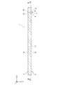
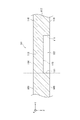
図1及び図2に示すように、本実施形態のカバーガラス1は、全体として平板状の略直方体であり、図1上側の表面3と、表面3に対向する図1下側の裏面5と、を有する。本明細書において、表面とは、カバーガラス1を含む組立体(アセンブリ)の外側の面、すなわち通常の使用状態において使用者が触れることができる面をいう。また、裏面とは、組立体の内側の面、すなわち通常の使用状態において使用者が触れることができない面をいう。また、以下の説明において、カバーガラス1の長手方向をX方向とし、短手方向をY方向とし、厚み方向をZ方向とする。   As shown in FIG. 1 and FIG. 2, the cover glass 1 of the present embodiment is a substantially flat rectangular parallelepiped as a whole, and includes a front surface 3 on the upper side in FIG. 1 and a rear surface 5 on the lower side in FIG. Have. In the present specification, the surface means an outer surface of the assembly (assembly) including the cover glass 1, that is, a surface that can be touched by a user in a normal use state. Further, the back surface means an inner surface of the assembly, that is, a surface that cannot be touched by a user in a normal use state. In the following description, the longitudinal direction of the cover glass 1 is the X direction, the short direction is the Y direction, and the thickness direction is the Z direction.

カバーガラス1の表面3又は裏面5には、少なくとも一つの凹部7が形成される。図1及び図2には、カバーガラス1の裏面5に、一つの凹部7が形成された例が示されている。凹部7は、カバーガラス1のX方向端部近傍で且つY方向中央部近傍に形成される。凹部7のX方向両側面9、9及びY方向両側面11、11は、Z方向に平行となるように延びている。なお、凹部7が形成される位置は、カバーガラス1の表面3又は裏面5であれば、任意の位置に設定して構わない。また、凹部7の形状や数も任意である。   At least one recess 7 is formed on the front surface 3 or the back surface 5 of the cover glass 1. FIG. 1 and FIG. 2 show an example in which one recess 7 is formed on the back surface 5 of the cover glass 1. The recess 7 is formed in the vicinity of the end portion in the X direction of the cover glass 1 and in the vicinity of the central portion in the Y direction. The X-direction side surfaces 9 and 9 and the Y-direction side surfaces 11 and 11 of the recess 7 extend so as to be parallel to the Z direction. In addition, as long as the position in which the recessed part 7 is formed is the surface 3 or the back surface 5 of the cover glass 1, you may set to arbitrary positions. Further, the shape and number of the recesses 7 are also arbitrary.

このように凹部7が設けられることにより、カバーガラス1には凹部7とX方向及びY方向で重なる位置において薄肉部13が形成されると共に、当該薄肉部13の周縁部に接続し、薄肉部13よりもZ方向厚みが大きい厚肉部17が形成される。薄肉部13及び厚肉部17の表面14、18は平面形状であり、面一形状を構成する。また、薄肉部13及び厚肉部17の裏面15、19も平面形状とされ、段差形状を構成する。   By providing the recess 7 in this manner, the cover glass 1 is formed with a thin portion 13 at a position overlapping the recess 7 in the X direction and the Y direction, and is connected to the peripheral portion of the thin portion 13, so that the thin portion A thick portion 17 having a thickness in the Z direction larger than 13 is formed. The surfaces 14 and 18 of the thin-walled portion 13 and the thick-walled portion 17 have a planar shape and form a flush surface. Further, the back surfaces 15 and 19 of the thin wall portion 13 and the thick wall portion 17 are also planar, and form a step shape.

凹部7が裏面5に設けられる構成においては、指紋認証センサ等の静電容量方式センサは、凹部7に配置されると共に、薄肉部13の表面14に当接した被検出物(例えば指)を検出する。このような構成においては、カバーガラス1の表面3が全面に亘って平坦となるので、美観が非常に優れる。   In the configuration in which the concave portion 7 is provided on the back surface 5, a capacitive sensor such as a fingerprint authentication sensor is disposed in the concave portion 7, and an object to be detected (for example, a finger) that is in contact with the surface 14 of the thin portion 13. To detect. In such a configuration, since the surface 3 of the cover glass 1 is flat over the entire surface, the aesthetic appearance is very excellent.

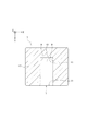
図3には、凹部7(薄肉部13)周辺の断面形状がより詳細に示されている。薄肉部13の表面14及び裏面15のうち少なくとも一方には、膜が形成されている。図3のカバーガラス1は、薄肉部13の表面14に形成された表面膜21と、裏面15に形成された裏面膜22と、凹部7のX方向側面9及びY方向側面11に形成された側面膜23と、を有する。   FIG. 3 shows the cross-sectional shape around the recess 7 (thin wall portion 13) in more detail. A film is formed on at least one of the front surface 14 and the back surface 15 of the thin portion 13. The cover glass 1 in FIG. 3 is formed on the surface film 21 formed on the surface 14 of the thin portion 13, the back film 22 formed on the back surface 15, and the X-direction side surface 9 and the Y-direction side surface 11 of the recess 7. And a side film 23.

これらの膜21、22、23は、それぞれ膜が形成された部分(表面14、裏面15、X方向側面9及びY方向側面11)が化学強化されることを抑制する。また、これらの膜21、22、23は、カバーガラス1の化学強化反応を緩和して、カバーガラス1に急激な変化を与えにくくするので、凹部7における化学強化による欠陥を低減できる。化学強化抑制効果を発揮するためには、膜21、22、23は酸化物や窒化物、炭化物、ホウ化物、ケイ化物、金属等を主成分として含むことが好ましい。なぜなら、前記のような物質を含む膜は、膜中でのナトリウムイオンやカリウムイオンの拡散係数がガラス中のそれより小さくなるからである。   These films 21, 22, and 23 suppress chemical strengthening of the portions where the films are formed (the front surface 14, the back surface 15, the X direction side surface 9, and the Y direction side surface 11). Moreover, since these films 21, 22, and 23 alleviate the chemical strengthening reaction of the cover glass 1 and make it difficult for the cover glass 1 to undergo a rapid change, defects due to the chemical strengthening in the recesses 7 can be reduced. In order to exhibit the chemical strengthening suppressing effect, the films 21, 22, and 23 preferably contain oxides, nitrides, carbides, borides, silicides, metals, and the like as main components. This is because a film containing such a substance has a smaller diffusion coefficient of sodium ions and potassium ions in the film than in glass.

上記酸化物としては、例えば、無アルカリ酸化物、アルカリ元素またはアルカリ土類元素を含む複合酸化物が挙げられるが、特にSiOが好ましい。主成分としてSiOを適用することにより、膜中でナトリウムイオンやカリウムイオンの拡散が適度に抑制される。また、膜の透過率が高く、屈折率がガラスと近いため、コーティングを施したことによる外観変化を最小限に抑えることができる。また、SiOを主成分とする膜は、物理的耐久性や化学的耐久性も高い。 Examples of the oxide include a non-alkali oxide, a composite oxide containing an alkali element or an alkaline earth element, and SiO 2 is particularly preferable. By applying SiO 2 as the main component, diffusion of sodium ions and potassium ions in the film is moderately suppressed. Further, since the transmittance of the film is high and the refractive index is close to that of glass, the change in appearance due to the coating can be minimized. Also, film composed mainly of SiO 2, the physical durability and chemical durability is high.

無アルカリ酸化物とは、アルカリ金属元素以外の元素からなる酸化物であって、アルカリ金属以外の元素を1種以上含む酸化物ならびに複合酸化物、又は2種類以上の酸化物及び複合酸化物の混合酸化物、若しくは上記酸化物や複合酸化物の積層体のことである。   An alkali-free oxide is an oxide composed of an element other than an alkali metal element, and is an oxide and composite oxide containing one or more elements other than an alkali metal, or two or more oxides and composite oxides. It is a mixed oxide or a laminate of the above oxides and composite oxides.

無アルカリ酸化物としては、ケイ素からなる酸化物、及び複合酸化物が少なくとも1種類以上含まれる酸化物が好ましい。このような酸化物を含む膜は、膜中でナトリウムイオンやカリウムイオンの拡散が適度に抑制される。また、膜の透過率が高く、屈折率がガラスと近いため、コーティングを施したことによる外観変化を最小限に抑えられる。また、このような酸化物を含む膜は、物理的耐久性や化学的耐久性も高い。   As the alkali-free oxide, an oxide comprising silicon and an oxide containing at least one composite oxide are preferable. In a film containing such an oxide, diffusion of sodium ions and potassium ions is moderately suppressed in the film. Further, since the transmittance of the film is high and the refractive index is close to that of glass, the appearance change due to the coating can be minimized. In addition, a film containing such an oxide has high physical durability and chemical durability.

上記窒化物としては、例えば、ケイ素、ホウ素、チタン等の窒化物が挙げられる。特にケイ素の窒化物が好ましい。なぜなら、膜の可視域での透過率が比較的高く、物理的耐久性、化学的耐久性に優れるからである。   Examples of the nitride include nitrides such as silicon, boron, and titanium. Silicon nitride is particularly preferable. This is because the transmittance of the membrane in the visible range is relatively high and the physical durability and chemical durability are excellent.

上記炭化物としては、例えば、炭化ケイ素や炭化チタン等の炭化物が挙げられる。   Examples of the carbide include carbides such as silicon carbide and titanium carbide.

上記金属としては、例えば、シリコン、チタン、アルミ、亜鉛、スズ、タンタル、ジルコニウム、ニオブ、インジウム、ハフニウム等が挙げられる。   Examples of the metal include silicon, titanium, aluminum, zinc, tin, tantalum, zirconium, niobium, indium, and hafnium.

膜21、22、23は、酸化物や窒化物、炭化物等のうち一つのみからなる膜でも、炭化物、フッ化物、硫化物など、その他の化合物が含まれてもよく、いずれの元素と組み合わせてもよい。ランタノイド系元素またはアクチノイド系元素などが少量ドープされたような膜でもよい。   The films 21, 22, and 23 may be films made of only one of oxide, nitride, carbide, etc., and may contain other compounds such as carbide, fluoride, sulfide, etc. May be. A film in which a small amount of a lanthanoid element or an actinoid element is doped may be used.

膜21、22、23と薄肉部13との合成静電容量は、好ましくは1×10⁻¹³F以上であり、より好ましくは5×10⁻¹³F以上であり、さらに好ましくは1×10⁻¹²F以上である。なぜなら、物理的な構造に起因する容量成分を示す寄生容量が小さくなりセンシング感度が高くなるためである。また、膜21、22、23と薄肉部13との合成静電容量は、好ましくは1×10⁻⁵F以下であり、より好ましくは1×10⁻⁶F以下であり、さらに好ましくは2×10⁻⁷F以下である。なぜなら温度、湿度等の外部環境の変化による感度の変化が小さく安定して使用できるためである。 The combined capacitance of the films 21, 22, 23 and the thin portion 13 is preferably 1 × 10 −13 F or more, more preferably 5 × 10 −13 F or more, and further preferably 1 × 10 −5. 12 F or more. This is because the parasitic capacitance indicating the capacitance component due to the physical structure is reduced and the sensing sensitivity is increased. The combined capacitance of the films 21, 22, 23 and the thin portion 13 is preferably 1 × 10 −5 F or less, more preferably 1 × 10 −6 F or less, and further preferably 2 ×. 10 −7 F or less. This is because sensitivity changes due to changes in the external environment such as temperature and humidity are small and can be used stably.

膜21、22、23の膜厚は10nm以上であり、好ましくは12nm以上であり、より好ましくは15nm以上であり、より好ましくは20nm以上であり、さらに好ましくは25nm以上である。膜厚が10nm以上であると、イオン交換阻害の効果により、膜21、22、23が形成された部分の化学強化が抑制できる。膜21、22、23の膜厚が厚くなるほど、化学強化抑制効果が高くなる。   The film thicknesses of the films 21, 22, and 23 are 10 nm or more, preferably 12 nm or more, more preferably 15 nm or more, more preferably 20 nm or more, and further preferably 25 nm or more. When the film thickness is 10 nm or more, chemical strengthening of the portions where the films 21, 22, and 23 are formed can be suppressed due to the effect of ion exchange inhibition. The thicker the films 21, 22, and 23, the higher the chemical strengthening suppression effect.

膜21、22、23の膜厚は1000nm以下であり、好ましくは500nm以下であり、より好ましくは200nm以下であり、より好ましくは100nm以下であり、さらに好ましくは50nm以下である。膜厚が1000nmを超えると、薄肉部13の反りがかえって大きくなるおそれがある。また、膜21、22、23がある部位とない部位の外観の差が大きくなるおそれがある。   The thicknesses of the films 21, 22, and 23 are 1000 nm or less, preferably 500 nm or less, more preferably 200 nm or less, more preferably 100 nm or less, and further preferably 50 nm or less. When the film thickness exceeds 1000 nm, the warp of the thin portion 13 may be increased. Moreover, there is a possibility that the difference in appearance between the site with and without the films 21, 22, and 23 increases.

膜21、22、23の膜厚はX線反射率(XRR:X−Ray Reflectivity)法により測定できる。この測定によって、カバーガラス1(薄肉部13及び厚肉部17)と膜21、22、23との界面が定義される。   The film thicknesses of the films 21, 22, and 23 can be measured by an X-ray reflectivity (XRR: X-Ray Reflectivity) method. By this measurement, the interface between the cover glass 1 (the thin portion 13 and the thick portion 17) and the films 21, 22, and 23 is defined.

表面14、裏面15、X方向側面9及びY方向側面11の面積に対する膜21、22、23の面積の比率で示される被覆率は、80%以上が好ましく、90%以上がより好ましく、95%以上がさらに好ましい。図3の例のように、表面14、裏面15、X方向側面9及びY方向側面11の全面が膜21、22、23によって覆われ、被覆率が100%である場合、良好な化学強化抑制効果が得られる。   The coverage shown by the ratio of the area of the films 21, 22, 23 to the area of the front surface 14, the back surface 15, the X direction side surface 9 and the Y direction side surface 11 is preferably 80% or more, more preferably 90% or more, and 95%. The above is more preferable. As shown in FIG. 3, when the entire surface 14, the back surface 15, the X-direction side surface 9 and the Y-direction side surface 11 are covered with the films 21, 22, and 23 and the coverage is 100%, good chemical strengthening suppression An effect is obtained.

膜21、22、23の膜密度は、好ましくは0.001mol/cm以上であり、より好ましくは0.005mol/cm以上であり、さらに好ましくは0.01mol/cm以上であり、よりさらに好ましくは0.03mol/cm以上である。膜密度が0.001mol/cm以上になると、イオン交換阻害の効果により、膜21、22、23が形成された部分の化学強化が抑制できる。 The film density of the films 21, 22, and 23 is preferably 0.001 mol / cm 3 or more, more preferably 0.005 mol / cm 3 or more, and still more preferably 0.01 mol / cm 3 or more. More preferably, it is 0.03 mol / cm 3 or more. When the film density is 0.001 mol / cm 3 or more, chemical strengthening of the portions where the films 21, 22, and 23 are formed can be suppressed due to the effect of inhibiting ion exchange.

膜21、22、23の膜密度は、好ましくは0.5mol/cm以下であり、より好ましくは0.2mol/cm以下であり、さらに好ましくは0.1mol/cm以下であり、よりさらに好ましくは0.05mol/cm以下である。膜密度が0.5mol/cmを超えると、カバーガラス1の化学強化が不十分になり、必要な強度を確保できないおそれがある。 The film density of the films 21, 22, and 23 is preferably 0.5 mol / cm 3 or less, more preferably 0.2 mol / cm 3 or less, still more preferably 0.1 mol / cm 3 or less, and more More preferably, it is 0.05 mol / cm 3 or less. If the film density exceeds 0.5 mol / cm 3 , the chemical strengthening of the cover glass 1 becomes insufficient, and the required strength may not be ensured.

膜密度はエリプソメトリーで屈折率を測定し、それによって膜の緻密さを評価することにより、求めることができる。膜密度は、例えば、スパッタ時に、アルゴンガスに対する酸素や窒素、炭化水素系ガス等の割合を変更することにより、調整できる。   The film density can be determined by measuring the refractive index by ellipsometry and thereby evaluating the film density. The film density can be adjusted, for example, by changing the ratio of oxygen, nitrogen, hydrocarbon gas, etc. to the argon gas during sputtering.

SiO膜を用いる場合、膜21、22、23のD線における屈折率nは、好ましくは1.46未満、より好ましくは1.45未満、さらに好ましくは1.44未満である。上記屈折率が1.46超であると、薄肉部13の反りがかえって大きくなるおそれがある。 When using a SiO 2 film, the refractive index n d of D line of film 21, 22, preferably less than 1.46, more preferably less than 1.45, more preferably less than 1.44. If the refractive index is greater than 1.46, the warp of the thin portion 13 may be increased.

これら、膜21、22、23を規定するパラメータ(膜厚、被覆率、膜密度、屈折率等)は、所望の化学強化抑制効果を満たすように適宜変更される。すなわち、化学強化後の薄肉部13の反りが大きい場合には、膜21、22、23の膜厚、被覆率、膜密度、屈折率を大きくすればよく、薄肉部13の反りが小さい場合には、膜21、22、23の膜厚、被覆率、膜密度、屈折率を小さくすればよい。   These parameters (film thickness, coverage, film density, refractive index, etc.) defining the films 21, 22, and 23 are appropriately changed so as to satisfy a desired chemical strengthening suppressing effect. That is, when the warp of the thin portion 13 after chemical strengthening is large, the film thickness, coverage, film density, and refractive index of the films 21, 22, and 23 may be increased, and when the warp of the thin portion 13 is small. In this case, the film thickness, coverage, film density, and refractive index of the films 21, 22, and 23 may be reduced.

なお、化学強化後における薄肉部13の反りを低減するためには、薄肉部13の表面14及び裏面15の少なくとも一方に膜(表面膜21又は裏面膜22)を形成すればよい。また、凹部7のX方向側面9及びY方向側面11には、側面膜23を形成してもよいし、形成しなくてもよい。   In order to reduce warping of the thin portion 13 after chemical strengthening, a film (surface film 21 or back surface film 22) may be formed on at least one of the front surface 14 and the back surface 15 of the thin portion 13. Further, the side film 23 may or may not be formed on the side surface 9 in the X direction and the side surface 11 in the Y direction of the recess 7.

すなわち、図4に示すように、表面膜21及び裏面膜22を形成し、側面膜23を形成しなくてもよい。図5に示すように、表面膜21のみを形成してもよい。図6に示すように、裏面膜22のみを形成してもよい。   That is, as shown in FIG. 4, the surface film 21 and the back film 22 may be formed, and the side film 23 may not be formed. As shown in FIG. 5, only the surface film 21 may be formed. As shown in FIG. 6, only the back film 22 may be formed.

以上より、膜21、22、23が形成された薄肉部13は、厚肉部17に比べ化学強化が抑制され、例えば、圧縮応力層の表面圧縮応力(Compressive Stress;CS)に差が生じる。薄肉部13の膜が形成された面のCSと、前記膜が形成された面と同一面の厚肉部17のCSとの差(ΔCS)が、30MPa以上となることが好ましい。これにより薄肉部13の化学強化時の反りを抑制できる。ΔCSは50MPa以上であることがより好ましく、これにより化学強化の反りをより効果的に抑制できる。また、ΔCSは500MPa以下が好ましく、450MPa以下がより好ましい。化学強化処理したカバーガラス1は実用上、剛性が必要となるためである。   As described above, the thin portion 13 on which the films 21, 22, and 23 are formed is less chemically strengthened than the thick portion 17, and, for example, a difference occurs in the surface compressive stress (CS) of the compressive stress layer. The difference (ΔCS) between the CS on the surface of the thin portion 13 on which the film is formed and the CS on the thick portion 17 on the same surface as the surface on which the film is formed is preferably 30 MPa or more. Thereby, the curvature at the time of chemical strengthening of the thin part 13 can be suppressed. ΔCS is more preferably 50 MPa or more, whereby the warp of chemical strengthening can be more effectively suppressed. ΔCS is preferably 500 MPa or less, and more preferably 450 MPa or less. This is because the chemically strengthened cover glass 1 requires rigidity for practical use.

図5および図6に示すように、薄肉部13の片面に膜が形成されている場合、薄肉部13の表面14のCSと厚肉部17の表面18のCSとの差、薄肉部13の裏面15のCSと厚肉部17の裏面19のCSとの差がそれぞれのΔCSとなる。図3および図4に示すように、薄肉部の両面に膜が形成されている場合には、表裏のうち少なくとも一面について考慮すればよい。   As shown in FIGS. 5 and 6, when a film is formed on one surface of the thin portion 13, the difference between the CS of the surface 14 of the thin portion 13 and the CS of the surface 18 of the thick portion 17, The difference between the CS on the back surface 15 and the CS on the back surface 19 of the thick portion 17 is the respective ΔCS. As shown in FIGS. 3 and 4, when films are formed on both surfaces of the thin portion, at least one of the front and back surfaces may be considered.

表面膜21及び裏面膜22を共に形成する場合は、これらの膜厚、被覆率、膜密度が互いに異なってもよい。これにより、化学強化抑制だけではなく、指滑り性も兼ね備えることができる。また、反射色を調整することによって、厚肉部17と薄肉部13での外観の差を小さくしてガラス部材に一体感を持たせたり、又は逆にその差を大きくして薄肉部13の視認性を高めたりできる。   When the surface film 21 and the back film 22 are formed together, their film thickness, coverage, and film density may be different from each other. Thereby, not only chemical reinforcement suppression but finger slipperiness can be provided. Further, by adjusting the reflection color, the difference in appearance between the thick portion 17 and the thin portion 13 is reduced to give the glass member a sense of unity, or conversely, the difference is increased to reduce the thickness of the thin portion 13. Visibility can be improved.

なお、凹部7は、図8に示すように、カバーガラス1の表面3に設けても構わない。凹部7が表面3に設けられる構成においては、静電容量方式センサは、カバーガラス1の裏面5において凹部7とZ方向に対向する位置、すなわち薄肉部13の裏面15に配置される。図3の例と異なりセンサは凹部7に配置されないので、X、Y、Z方向のうち少なくとも一方向において、センサの寸法を凹部7の寸法よりも大きくすることができる。したがって、寸法が比較的大きいセンサを薄肉部13の裏面15に配置することで、薄肉部13を補強できる。そして、当該センサは、薄肉部13の表面14(表面膜21)に当接した被検出物を検出する。また、このような構成においては、携帯情報端末の使用者は、凹部7によって、薄肉部13の位置及び薄肉部13の裏面15に配置されたセンサの位置を、視覚や触覚等により容易に認識できる。   In addition, you may provide the recessed part 7 in the surface 3 of the cover glass 1, as shown in FIG. In the configuration in which the recess 7 is provided on the front surface 3, the capacitance type sensor is disposed on the back surface 5 of the cover glass 1 so as to face the recess 7 in the Z direction, that is, on the back surface 15 of the thin portion 13. Unlike the example of FIG. 3, since the sensor is not arranged in the recess 7, the sensor can be made larger than the recess 7 in at least one of the X, Y, and Z directions. Therefore, the thin portion 13 can be reinforced by arranging a sensor having a relatively large size on the back surface 15 of the thin portion 13. The sensor detects an object to be detected that is in contact with the surface 14 (surface film 21) of the thin portion 13. In such a configuration, the user of the portable information terminal can easily recognize the position of the thin portion 13 and the position of the sensor disposed on the back surface 15 of the thin portion 13 by visual or tactile sense using the concave portion 7. it can.

カバーガラス1の表面3に凹部7を設ける構成においても、薄肉部13の表面14及び裏面15のうち少なくとも一方には、膜(表面膜21又は裏面膜22)が形成される。図8には、表面膜21が薄肉部13の表面14に形成され、裏面膜22が薄肉部13の裏面15に形成され、側面膜23が凹部7のX方向側面9及びY方向側面11に形成された例が示されている。   Even in the configuration in which the concave portion 7 is provided on the surface 3 of the cover glass 1, a film (surface film 21 or back film 22) is formed on at least one of the surface 14 and the back surface 15 of the thin portion 13. In FIG. 8, the surface film 21 is formed on the surface 14 of the thin part 13, the back film 22 is formed on the back surface 15 of the thin part 13, and the side film 23 is formed on the X direction side surface 9 and the Y direction side surface 11 of the recess 7. A formed example is shown.

上述したように、本実施形態のカバーガラス1は携帯情報端末の保護用途に限定されるものではないが、特に携帯情報端末の保護のために用いられる場合、厚肉部17のZ方向厚みt2は、2mm以下であり、好ましくは1.5mm以下であり、より好ましくは0.8mm以下である。なぜなら、厚肉部17のZ方向厚みt2が2mmよりも厚い場合、薄肉部13のZ方向厚みt1との差が大きくなり、加工が困難になるほか、携帯情報端末の使用には重量増になるからである。また、厚肉部17のZ方向厚みt2は、その剛性を高めるため、0.1mm以上であり、好ましくは0.15mm以上であり、より好ましくは0.2mm以上である。0.1mmより薄い場合、剛性が低くなり過ぎ、携帯情報端末の保護の用をなさないおそれがある。   As described above, the cover glass 1 of the present embodiment is not limited to the protection application of the portable information terminal, but particularly when used for protection of the portable information terminal, the thickness t2 of the thick portion 17 in the Z direction. Is 2 mm or less, preferably 1.5 mm or less, more preferably 0.8 mm or less. This is because if the thickness t2 of the thick portion 17 is larger than 2 mm, the difference from the thickness t1 of the thin portion 13 becomes large, making the processing difficult, and increasing the weight for use of the portable information terminal. Because it becomes. Further, the thickness t2 of the thick portion 17 in the Z direction is 0.1 mm or more, preferably 0.15 mm or more, and more preferably 0.2 mm or more in order to increase its rigidity. If it is thinner than 0.1 mm, the rigidity becomes too low, and there is a risk that the portable information terminal will not be used for protection.

また、薄肉部13のZ方向厚みt1は、0.4mm以下であり、好ましくは0.35mm以下であり、より好ましくは0.3mm以下であり、さらに好ましくは0.25mm以下であり、特に好ましくは0.2mm以下であり、最も好ましくは0.1mm以下である。特に、薄肉部13の裏面15に静電容量式センサが配置された場合、薄肉部13が薄いほど、検出される静電容量が大きくなり、センシング感度が向上する。例えば、指先の指紋の微細な凹凸を検出する指紋認証の場合にも、指先の指紋の微細な凹凸に応じた静電容量の差が大きくなるため、高いセンシング感度での検出を行うことができる。一方、薄肉部13のZ方向厚みt1の下限は、特に限定されないが、薄肉部13が過度に薄くなると、強度が低下し、センサ等の保護部としての適切な機能を発揮し難くなる傾向がある。したがって、薄肉部13のZ方向厚みt1は、例えば0.01mm以上であり、好ましくは0.05mm以上である。なお、薄肉部のZ方向厚みt1と、厚肉部のZ方向厚みt2と、凹部7のZ方向深さdと、の関係はt1=t2−dで表される。   Further, the thickness t1 of the thin portion 13 in the Z direction is 0.4 mm or less, preferably 0.35 mm or less, more preferably 0.3 mm or less, still more preferably 0.25 mm or less, particularly preferably. Is 0.2 mm or less, and most preferably 0.1 mm or less. In particular, when a capacitive sensor is disposed on the back surface 15 of the thin portion 13, the detected capacitance increases as the thin portion 13 is thinner, and the sensing sensitivity is improved. For example, even in the case of fingerprint authentication that detects fine irregularities on a fingertip fingerprint, the difference in capacitance according to the minute irregularities on the fingerprint on the fingertip becomes large, so detection with high sensing sensitivity can be performed. . On the other hand, the lower limit of the Z-direction thickness t1 of the thin portion 13 is not particularly limited. However, when the thin portion 13 becomes excessively thin, the strength tends to decrease and it is difficult to exert an appropriate function as a protective portion such as a sensor. is there. Therefore, the Z-direction thickness t1 of the thin portion 13 is, for example, 0.01 mm or more, and preferably 0.05 mm or more. The relationship between the Z-direction thickness t1 of the thin portion, the Z-direction thickness t2 of the thick portion, and the Z-direction depth d of the recess 7 is represented by t1 = t2-d.

薄肉部13のZ方向厚みt1の、厚肉部17のZ方向厚みt2に対する比率(t1/t2)は、0.05以上であることが好ましく、0.1以上であることがより好ましく、0.15以上であることがさらに好ましい。比率(t1/t2)が0.05未満であると、薄肉部13の剛性が低くなりすぎるおそれがある。薄肉部13の剛性を担保しようとした場合は、厚肉部17の厚みが大きくなりすぎるおそれがある。   The ratio (t1 / t2) of the Z-direction thickness t1 of the thin portion 13 to the Z-direction thickness t2 of the thick portion 17 is preferably 0.05 or more, more preferably 0.1 or more, 0 More preferably, it is 15 or more. If the ratio (t1 / t2) is less than 0.05, the rigidity of the thin portion 13 may be too low. When trying to secure the rigidity of the thin portion 13, the thickness of the thick portion 17 may be too large.

比率(t1/t2)は、0.9以下であることが好ましく、0.8以下であることがより好ましく、0.6以下であることがさらに好ましい。比率(t1/t2)が0.9より大きいと、薄肉部13に配置するセンサの機能が十分に発揮されないおそれがある。   The ratio (t1 / t2) is preferably 0.9 or less, more preferably 0.8 or less, and even more preferably 0.6 or less. If the ratio (t1 / t2) is greater than 0.9, the function of the sensor disposed in the thin portion 13 may not be sufficiently exhibited.

なお、比率(t1/t2)が0.05〜0.9の範囲である場合は、薄肉部13の剛性が低くなり過ぎず、薄肉部13に配置するセンサも十分に機能できるようになる。   When the ratio (t1 / t2) is in the range of 0.05 to 0.9, the rigidity of the thin portion 13 does not become too low, and the sensor disposed in the thin portion 13 can sufficiently function.

なお、カバーガラス1に凹部7が複数設けられることにより、薄肉部13が複数形成される場合であっても、上記比率(t1/t2)の好ましい範囲は同様である。   In addition, the preferable range of the said ratio (t1 / t2) is the same even if it is a case where the thin part 13 is formed in multiple numbers by providing the recessed part 7 in the cover glass 1. FIG.

また、薄肉部13の表面14又は裏面15の面積をs1とし、厚肉部17の表面18又は裏面19の面積をs2とすると、面積s1の面積s2に対する比率(s1/s2)は、0.001以上であることが好ましく、0.002以上であることがより好ましく、0.005以上であることがさらに好ましい。比率(s1/s2)が0.001未満であると、薄肉部13の面積s1が小さくなりすぎ、指紋認証のセンシング性能が低下するおそれがある。または、厚肉部17の面積s2が大きくなりすぎ、PDAとしての携帯性が低下するおそれがある。   When the area of the front surface 14 or the back surface 15 of the thin portion 13 is s1, and the area of the front surface 18 or the back surface 19 of the thick portion 17 is s2, the ratio of the area s1 to the area s2 (s1 / s2) is 0. It is preferably 001 or more, more preferably 0.002 or more, and further preferably 0.005 or more. If the ratio (s1 / s2) is less than 0.001, the area s1 of the thin-walled portion 13 becomes too small, and there is a risk that the sensing performance of fingerprint authentication will deteriorate. Alternatively, the area s2 of the thick portion 17 becomes too large, and portability as a PDA may be reduced.

また、比率(s1/s2)は、0.9以下であることが好ましく、0.7以下であることがより好ましく、0.5以下であることがさらに好ましい。比率(s1/s2)が0.9より大きいと、薄肉部13の面積s1が大きくなりすぎ、カバーガラス1全体としての剛性を担保できないおそれがある。   Further, the ratio (s1 / s2) is preferably 0.9 or less, more preferably 0.7 or less, and further preferably 0.5 or less. If the ratio (s1 / s2) is greater than 0.9, the area s1 of the thin portion 13 becomes too large, and there is a possibility that the rigidity of the cover glass 1 as a whole cannot be secured.

なお、比率(s1/s2)が0.001〜0.9の範囲である場合は、指紋認証センシング性能を低下させることなく、またカバーガラス1全体の剛性も担保できるようになる。   When the ratio (s1 / s2) is in the range of 0.001 to 0.9, the rigidity of the cover glass 1 can be ensured without deteriorating the fingerprint authentication sensing performance.

なお、上記比率(s1/s2)の好ましい範囲は、カバーガラス1に凹部7が一つ設けられることにより薄肉部13が一つ形成される場合のものであって、カバーガラス1に凹部7が複数設けられることにより薄肉部13が複数形成される場合には、以下の関係式を満たすように設定される。すなわち、複数の薄肉部13の表面14又は裏面15の合計面積をs1allとし、厚肉部17の表面18又は裏面19の面積をs2とすると、合計面積s1allの面積s2に対する比率(s1all/s2)は、0.001以上であることが好ましく、0.002以上であることがより好ましく、0.005以上であることがさらに好ましい。比率(s1all/s2)が0.001未満であると、薄肉部13の面積s1が小さくなりすぎ、指紋認証のセンシング性能が低下するおそれがある。または、厚肉部17の面積s2が大きくなりすぎ、PDAとしての携帯性が低下するおそれがある。 In addition, the preferable range of the said ratio (s1 / s2) is a thing when one thin part 13 is formed by providing one recessed part 7 in the cover glass 1, Comprising: The recessed part 7 is formed in the cover glass 1. When a plurality of thin portions 13 are formed by providing a plurality, the following relational expression is set. That is, the total area of the surface 14 or rear surface 15 of the plurality of thin portions 13 and s1 all, when the area of the surface 18 or rear surface 19 of the thick portion 17 and s2, the ratio to the area s2 of the total area s1 all (s1 all / S2) is preferably 0.001 or more, more preferably 0.002 or more, and further preferably 0.005 or more. If the ratio (s1 all / s2) is less than 0.001, the area s1 of the thin portion 13 becomes too small, and the sensing performance of fingerprint authentication may be deteriorated. Alternatively, the area s2 of the thick portion 17 becomes too large, and portability as a PDA may be reduced.

また、合計面積s1allの面積s2に対する比率(s1all/s2)は、0.9以下であることが好ましく、0.7以下であることがより好ましく、0.5以下であることがさらに好ましい。比率(s1all/s2)が0.9より大きいと、薄肉部13の面積s1が大きくなりすぎ、カバーガラス1全体としての剛性を担保できないおそれがある。 The ratio (s1 all / s2) of the total area s1 all to the area s2 is preferably 0.9 or less, more preferably 0.7 or less, and even more preferably 0.5 or less. . If the ratio (s1 all / s2) is greater than 0.9, the area s1 of the thin portion 13 becomes too large, and the rigidity of the cover glass 1 as a whole may not be secured.

薄肉部13のヤング率は60GPa以上であり、好ましくは65GPa以上であり、より好ましくは70GPa以上である。薄肉部13のヤング率が60GPa以上であると、外部からの衝突物との衝突に起因する薄肉部13の破損を十分に防止できる。また、静電容量方式センサが凹部7に配置される場合には、スマートフォン等の落下や衝突に起因する薄肉部13の破損を十分に防止できる。さらに、薄肉部13により保護されるセンサの破損等を、十分に防止できる。また、薄肉部13のヤング率の上限は特に限定されないが、生産性の観点から、薄肉部13のヤング率は、例えば200GPa以下であり、好ましくは150GPa以下である。   The Young's modulus of the thin portion 13 is 60 GPa or more, preferably 65 GPa or more, and more preferably 70 GPa or more. When the Young's modulus of the thin-walled portion 13 is 60 GPa or more, the thin-walled portion 13 can be sufficiently prevented from being damaged due to a collision with an external collision object. Moreover, when a capacitive sensor is arrange | positioned at the recessed part 7, damage to the thin part 13 resulting from fall or collision of a smart phone etc. can fully be prevented. Furthermore, damage to the sensor protected by the thin portion 13 can be sufficiently prevented. Moreover, although the upper limit of the Young's modulus of the thin part 13 is not specifically limited, From a viewpoint of productivity, the Young's modulus of the thin part 13 is 200 GPa or less, for example, Preferably it is 150 GPa or less.

薄肉部13のビッカース硬度Hvは、好ましくは3.9GPa以上であり、より好ましくは4.9GPa以上である。薄肉部13のビッカース硬度が3.9GPa以上であると、外部からの衝突物との衝突に起因する薄肉部13の擦傷を十分に防止できる。また、静電容量方式センサが凹部7に配置される場合には、スマートフォン等の落下や衝突に起因する薄肉部13の擦傷を十分に防止できる。さらに、薄肉部13により保護されるセンサの破損等を、十分に防止できる。また、薄肉部13のビッカース硬度の上限は、特に限定されないが、過度に高すぎると研磨や加工が困難となる場合がある。したがって、当該化学強化ガラスのビッカース硬度は、例えば12GPa以下であり、好ましくは10GPa以下である。なお、ビッカース硬度は、例えば日本工業規格JIS Z 2244に記載された、ビッカース硬さ試験により測定できる。   The Vickers hardness Hv of the thin portion 13 is preferably 3.9 GPa or more, more preferably 4.9 GPa or more. When the Vickers hardness of the thin-walled portion 13 is 3.9 GPa or more, the thin-walled portion 13 can be sufficiently prevented from being scratched due to a collision with a colliding object from the outside. Further, when the capacitive sensor is disposed in the recess 7, it is possible to sufficiently prevent the thin-walled portion 13 from being scratched due to dropping or collision of a smartphone or the like. Furthermore, damage to the sensor protected by the thin portion 13 can be sufficiently prevented. In addition, the upper limit of the Vickers hardness of the thin portion 13 is not particularly limited, but if it is too high, polishing and processing may be difficult. Accordingly, the Vickers hardness of the chemically strengthened glass is, for example, 12 GPa or less, and preferably 10 GPa or less. The Vickers hardness can be measured by, for example, a Vickers hardness test described in Japanese Industrial Standard JIS Z 2244.

薄肉部13の周波数1MHzでの比誘電率は、好ましくは7以上であり、より好ましくは7.2以上であり、さらに好ましくは7.5以上である。静電容量方式センサが薄肉部13の裏面15に配置される場合、薄肉部13の比誘電率を高くすることにより、検出される静電容量を大きくすることができ、優れたセンシング感度を実現できる。特に、薄肉部13の周波数1MHzでの比誘電率が7以上であると、指先の指紋の微細な凹凸を検出する指紋認証の場合にも、指先の指紋の微細な凹凸に応じた静電容量の差が大きくなるため、高いセンシング感度で検出できる。また、薄肉部13の比誘電率の上限については、特に限定されないが、過度に高すぎると誘電損失が大きくなり、消費電力が増加し、また、反応が遅くなる場合がある。したがって、薄肉部13の周波数1MHzでの比誘電率は、例えば好ましくは20以下であり、より好ましくは15以下である。比誘電率は、カバーガラス1の両面に電極を作製したキャパシタンスの静電容量を測定することによって得られる。   The relative dielectric constant of the thin portion 13 at a frequency of 1 MHz is preferably 7 or more, more preferably 7.2 or more, and further preferably 7.5 or more. When the capacitance type sensor is disposed on the back surface 15 of the thin portion 13, the detected capacitance can be increased by increasing the relative dielectric constant of the thin portion 13, thereby realizing excellent sensing sensitivity. it can. In particular, when the relative permittivity of the thin portion 13 at a frequency of 1 MHz is 7 or more, the capacitance corresponding to the fine irregularities of the fingertip fingerprint is also obtained in the case of fingerprint authentication for detecting the fine irregularities of the fingertip fingerprint. Because the difference between the two becomes large, detection is possible with high sensing sensitivity. The upper limit of the relative dielectric constant of the thin portion 13 is not particularly limited, but if it is too high, the dielectric loss increases, the power consumption increases, and the reaction may become slow. Therefore, the relative dielectric constant of the thin portion 13 at a frequency of 1 MHz is, for example, preferably 20 or less, and more preferably 15 or less. The relative dielectric constant is obtained by measuring the capacitance of the capacitance in which electrodes are formed on both surfaces of the cover glass 1.

カバーガラス1の裏面5には、印刷層が設けられることが好ましい。特に、図3に示したように、凹部7がカバーガラス1の裏面に設けられる場合には、凹部7(薄肉部13の裏面15)にも印刷層を設けることが好ましい。このような印刷層を設けることにより、カバーガラス1の保護対象である携帯情報端末や、薄肉部13の裏面15に配置された静電容量方式センサが、カバーガラス1を介して視認されることを効果的に防止できる。また、所望の色を付与でき、優れた外観性を得られる。   It is preferable that a printed layer is provided on the back surface 5 of the cover glass 1. In particular, as shown in FIG. 3, when the concave portion 7 is provided on the back surface of the cover glass 1, it is preferable to provide a printing layer also on the concave portion 7 (the back surface 15 of the thin portion 13). By providing such a printed layer, the portable information terminal that is the protection target of the cover glass 1 and the capacitive sensor arranged on the back surface 15 of the thin portion 13 are visually recognized through the cover glass 1. Can be effectively prevented. Moreover, a desired color can be imparted and an excellent appearance can be obtained.

印刷層は、例えば、所定の色材を含むインク組成物により形成できる。当該インク組成物は、色材の他、必要に応じてバインダー、分散剤や溶剤などを含むものである。色材は、顔料や染料などいずれの色材(着色剤)であってもよく、単独で又は2種以上を組み合わせて使用できる。なお、色材は所望される色によって適宜選択できるが、例えば、遮光性が求められる場合には、黒系色材等が好ましく用いられる。また、バインダーは、特に制限されず、例えば、ポリウレタン系樹脂、フェノール系樹脂、エポキシ系樹脂、尿素メラミン系樹脂、シリコーン系樹脂、フェノキシ樹脂、メタクリル系樹脂、アクリル系樹脂、ポリアリレート樹脂、ポリエステル系樹脂、ポリオレフィン系樹脂、ポリスチレン系樹脂、ポリ塩化ビニル、塩化ビニル−酢酸ビニル共重合体、ポリ酢酸ビニル、ポリ塩化ビニリデン、ポリカーボネート、セルロース類、ポリアセタール等の公知の樹脂(熱可塑性樹脂、熱硬化性樹脂や光硬化性樹脂など)等が挙げられる。バインダーは単独で又は2種以上を組み合わせて使用できる。   The print layer can be formed from, for example, an ink composition containing a predetermined color material. The ink composition contains, in addition to the color material, a binder, a dispersant, a solvent, and the like as necessary. The color material may be any color material (colorant) such as a pigment or a dye, and can be used alone or in combination of two or more. The color material can be appropriately selected depending on the desired color. For example, when a light shielding property is required, a black color material or the like is preferably used. The binder is not particularly limited, and for example, polyurethane resin, phenol resin, epoxy resin, urea melamine resin, silicone resin, phenoxy resin, methacrylic resin, acrylic resin, polyarylate resin, polyester type Resins, polyolefin resins, polystyrene resins, polyvinyl chloride, vinyl chloride-vinyl acetate copolymers, polyvinyl acetate, polyvinylidene chloride, polycarbonate, celluloses, polyacetal, and other known resins (thermoplastic resins, thermosetting Resin, photocurable resin, etc.). A binder can be used individually or in combination of 2 or more types.

印刷層を形成するための印刷法は特に限定されるものではなく、グラビア印刷法、フレキソ印刷法、オフセット印刷法、凸版印刷法、スクリーン印刷法、パッド印刷法、スプレー印刷法などの適宜な印刷法を適用できる。   The printing method for forming the printing layer is not particularly limited, and appropriate printing such as gravure printing method, flexographic printing method, offset printing method, letterpress printing method, screen printing method, pad printing method, spray printing method, etc. The law can be applied.

ここで、凹部7がカバーガラス1の表面3に設けられる場合、平面形状である裏面5に印刷層を形成することは容易である。凹部7の側部または底部に対応する場所に色を変えることで、視覚的に場所を解り易くすることも可能である。また、側部に対応する場所を鏡面反射印刷(例えばシルバー印刷)にすると、側部の曲率を持った形状がレンズ効果を示し、側部に対応する反射がカバーガラスの角度を変えても広い角度で反射するため、キラキラして高級感を演出できる。   Here, when the recessed part 7 is provided in the surface 3 of the cover glass 1, it is easy to form a printing layer in the back surface 5 which is planar shape. By changing the color to a location corresponding to the side or bottom of the recess 7, it is possible to make the location easy to understand visually. Also, if the location corresponding to the side part is specular reflection printing (for example, silver printing), the shape having the curvature of the side part shows the lens effect, and the reflection corresponding to the side part is wide even if the angle of the cover glass is changed. Because it reflects at an angle, it can sparkle and produce a high-class feel.

一方、凹部7がカバーガラス1の裏面5に設けられる場合、印刷は、当該凹部7と、カバーガラス1の裏面5において凹部7が形成されない平坦部分と、で個別に実施されることが好ましい。なぜなら、スクリーン印刷法等の印刷方向では、形状追従性がそれ程高くないため、凹部7と、凹部7が形成されない平坦部分と、を一度に印刷することが難しいからである。したがって、これらの部分の印刷を個別に実施することにより高精度な印刷を実現できる。また、凹部7と凹部7が形成されない平坦部分とで印刷の色彩またはテクスチャを変えることにより、センサーの位置を視覚的に分かりやすく表示でき、デザイン上のアクセントとすることもできる。   On the other hand, when the recessed part 7 is provided in the back surface 5 of the cover glass 1, it is preferable that printing is separately implemented by the said recessed part 7 and the flat part in which the recessed part 7 is not formed in the back surface 5 of the cover glass 1. FIG. This is because the shape followability is not so high in the printing direction such as the screen printing method, and it is difficult to print the concave portion 7 and the flat portion where the concave portion 7 is not formed at a time. Therefore, highly accurate printing can be realized by individually printing these portions. In addition, by changing the color or texture of printing between the concave portion 7 and the flat portion where the concave portion 7 is not formed, the position of the sensor can be displayed in a visually easy-to-understand manner, which can be used as an accent on the design.

より具体的には、裏面5において凹部7が形成されない平坦部分には、スクリーン印刷法等によって第一印刷層が設けられる。なお、スクリーン印刷とは、開口部を有するスクリーン上に印刷材料を載置した後、スクリーン上でスキージを押圧摺動させ、スクリーンの開口部から印刷材料を押し出して、開口部のパターンを印刷する方法をいう。また、凹部7は曲面形状である側面を有するので、当該凹部7に対してはパッド印刷法によって印刷を行うことが好適である。これにより、凹部7の底面及び側面には第二印刷層が形成される。ここで、パッド印刷法とは、表面にインクパターンを設けたやわらかいパッド(例えば、シリコーン製パッド)を、目的基材に押付けてインクパターンを基材表面に転写することにより印刷する方法である。パッド印刷は、タコ印刷又はタンポ印刷と呼ばれることもある。このように、パッド印刷法では、比較的やわらかく形状追従性のよいパッドが用いられるので、凹部の側面に対する印刷は、パッド印刷法によって行うのが好ましい。一方、スクリーン印刷法等の印刷方法では形状追従性がそれ程高くなく、インクが側面に印刷できないため不適である。なお、第一及び第二印刷層、に対する印刷の順序は特に限定されない。   More specifically, a first printed layer is provided on a flat portion where the concave portion 7 is not formed on the back surface 5 by a screen printing method or the like. In the screen printing, after a printing material is placed on a screen having an opening, a squeegee is pressed and slid on the screen, and the printing material is pushed out from the opening of the screen to print a pattern of the opening. Say the method. Moreover, since the recessed part 7 has a side surface which is a curved surface shape, it is preferable to print the recessed part 7 by a pad printing method. Thereby, the second printed layer is formed on the bottom surface and the side surface of the recess 7. Here, the pad printing method is a method of printing by pressing a soft pad (for example, a silicone pad) provided with an ink pattern on the surface against a target substrate and transferring the ink pattern onto the surface of the substrate. Pad printing is sometimes called tacho printing or tampo printing. Thus, in the pad printing method, a pad that is relatively soft and has good shape followability is used. Therefore, it is preferable to perform printing on the side surface of the concave portion by the pad printing method. On the other hand, the printing method such as the screen printing method is not suitable because the shape following property is not so high and the ink cannot be printed on the side surface. The order of printing on the first and second print layers is not particularly limited.

また、裏面5において凹部7が形成されない平坦部分と、凹部7の平坦形状の底面と、曲面形状の側面と、で個別に印刷しても構わない。この場合、裏面5において凹部7が形成されない平坦部分には、スクリーン印刷法等によって第一印刷層が設けられる。次に、凹部7の底面には、スクリーン印刷法等によって第二印刷層が設けられる。そして、凹部7の側面には、パッド印刷法によって第三印刷層が設けられる。底面にパッド印刷がされないように、パッドは底面に対応する部分を有さない筒形状とされる。このように、凹部7の底面及び側面を別に印刷することで、底面に形成される第二印刷層の膜厚や平坦性の制御が正確になる。したがって、凹部7の底面に静電容量方式センサーを配置した場合のセンサー感度を向上できる。なお、第一〜第三印刷層に対する印刷の順番は特に限定されない。また、第一印刷層と第二印刷層と第三印刷層とで印刷の色彩またはテクスチャを変えることにより、センサーの位置を視覚的に分かりやすく表示でき、デザイン上のアクセントとすることもできる。例えば、第一印刷層と第二印刷層を同色にし、第三印刷層を異なる色の印刷とした場合、第三印刷層が環状のパターンとして認識されるデザインとすることができる。   Moreover, you may print separately by the flat part in which the recessed part 7 is not formed in the back surface 5, the flat bottom face of the recessed part 7, and the curved-surface side. In this case, a first printing layer is provided on a flat portion where the concave portion 7 is not formed on the back surface 5 by a screen printing method or the like. Next, a second printing layer is provided on the bottom surface of the recess 7 by a screen printing method or the like. And the 3rd printing layer is provided in the side surface of the recessed part 7 by the pad printing method. In order to prevent pad printing on the bottom surface, the pad has a cylindrical shape having no portion corresponding to the bottom surface. In this way, by separately printing the bottom surface and the side surface of the recess 7, the control of the film thickness and flatness of the second print layer formed on the bottom surface becomes accurate. Therefore, it is possible to improve the sensor sensitivity when a capacitive sensor is disposed on the bottom surface of the recess 7. The order of printing for the first to third print layers is not particularly limited. In addition, by changing the printing color or texture in the first printing layer, the second printing layer, and the third printing layer, the position of the sensor can be displayed visually intelligibly, and it can be used as an accent on the design. For example, when the first print layer and the second print layer are the same color and the third print layer is printed in a different color, the design can be such that the third print layer is recognized as an annular pattern.

なお、裏面5において凹部7が形成されない部分や、凹部7の底面等、平坦部分に対する印刷法は、スクリーン印刷法によるものに限られず、印刷層の膜厚等を正確に制御できるものであれば、ロータリースクリーン印刷法、凸版印刷法、オフセット印刷法、スプレー印刷法等によるものでも構わない。また、静電複写法や熱転写法、インクジェット法等によるプリントでも構わない。   In addition, the printing method with respect to flat parts, such as the part in which the recessed part 7 is not formed in the back surface 5, and the bottom face of the recessed part 7, is not restricted to the thing by a screen printing method, if the film thickness etc. of a printing layer can be controlled accurately. Alternatively, a rotary screen printing method, a relief printing method, an offset printing method, a spray printing method, or the like may be used. Also, printing by electrostatic copying method, thermal transfer method, ink jet method or the like may be used.

また、凹部7の底面が中心部に向かうにしたがってZ方向に突出する形状である場合のように、凹部7の底面が曲面形状である場合には、底面に対する印刷もパッド印刷法で行うことが好ましい。   In addition, when the bottom surface of the recess 7 has a curved shape, such as when the bottom surface of the recess 7 protrudes in the Z direction toward the center, printing on the bottom surface can also be performed by the pad printing method. preferable.

なお、凹部7の側面や、突出形状を有する場合の底面等、曲面形状に対する印刷法は、当該曲面形状への追従性が良好であればパッド印刷法に限定されず、例えばスプレー印刷法を採用してもよい。   In addition, the printing method for the curved surface shape such as the side surface of the recess 7 or the bottom surface in the case of having a protruding shape is not limited to the pad printing method as long as the followability to the curved surface shape is good. For example, a spray printing method is adopted. May be.

このようなカバーガラス1によれば、携帯情報端末等の任意の面(例えば表面や側面)を保護するために筐体等に組み込まれる際、薄肉部13の裏面15に静電容量方式センサ等の各種装置を配置できる。ここで、薄肉部13の裏面15に組み込んだセンサは、Z方向に対向する薄肉部13によって保護されるので、センサカバー等の異種材料を併用することなく、材料的に一様で統一感のある意匠性に優れたカバーガラス1を実現できる。また、部材点数が少なく済み、組立工程を簡略化できるので、コスト削減にも多大な効果がある。   According to such a cover glass 1, a capacitance sensor or the like is provided on the back surface 15 of the thin portion 13 when it is incorporated in a housing or the like in order to protect an arbitrary surface (for example, a front surface or a side surface) of a portable information terminal or the like. Various devices can be arranged. Here, since the sensor incorporated in the back surface 15 of the thin wall portion 13 is protected by the thin wall portion 13 facing in the Z direction, the material is uniform and uniform without using different materials such as a sensor cover. The cover glass 1 excellent in a certain design property can be realized. Further, since the number of members is small and the assembly process can be simplified, there is a great effect in cost reduction.

(カバーガラスの製造方法)
次に、本実施形態のカバーガラス1が化学強化ガラスである場合の、当該カバーガラス1の製造方法について説明する。先ず、各成分の原料を後述する組成となるように調合し、ガラス溶融窯で加熱溶融する。バブリング、撹拌、清澄剤の添加等によりガラスを均質化し、従来公知の成形法により所定の厚さのガラス板に成形し、徐冷する。ガラスの成形法としては、例えば、フロート法、プレス法、フュージョン法、ダウンドロー法及びロールアウト法が挙げられる。特に、大量生産に適したフロート法が好適である。また、フロート法以外の連続成形法、すなわち、フュージョン法およびダウンドロー法も好適である。任意の成形法により平板状に成形されたガラス部材は、徐冷された後、所望のサイズ(カバーガラス1のサイズ)に切断され、研磨加工が施される。これにより、図9に示すような、平面状の表面103及び裏面105を有し、全体として平板状であるガラス部材101が得られる。
(Method for manufacturing cover glass)
Next, the manufacturing method of the said cover glass 1 in case the cover glass 1 of this embodiment is chemically strengthened glass is demonstrated. First, the raw materials of each component are prepared so as to have the composition described later, and heated and melted in a glass melting furnace. The glass is homogenized by bubbling, stirring, adding a clarifying agent, etc., formed into a glass plate having a predetermined thickness by a conventionally known forming method, and gradually cooled. Examples of the glass forming method include a float method, a press method, a fusion method, a downdraw method, and a rollout method. In particular, a float method suitable for mass production is suitable. Further, continuous molding methods other than the float method, that is, the fusion method and the downdraw method are also suitable. The glass member formed into a flat plate shape by an arbitrary forming method is gradually cooled, then cut into a desired size (the size of the cover glass 1), and subjected to a polishing process. As a result, a glass member 101 having a flat surface 103 and a back surface 105 as shown in FIG.

次に、図10に示すように、ガラス部材101の裏面105にエッチング処理や機械加工を施すことにより、凹部107を設ける。   Next, as shown in FIG. 10, the concave portion 107 is provided by performing etching or machining on the back surface 105 of the glass member 101.

エッチング方法は、ウェットエッチング及びドライエッチングのどちらでもよいが、コストの観点からウェットエッチングが好ましい。エッチャントとしては、ウェットエッチングの場合には、フッ酸を主成分とする溶液が挙げられ、ドライエッチングの場合には、フッ素系ガス等が挙げられる。   The etching method may be either wet etching or dry etching, but wet etching is preferable from the viewpoint of cost. Examples of the etchant include a solution containing hydrofluoric acid as a main component in the case of wet etching, and a fluorine-based gas in the case of dry etching.

また、エッチング処理は、ガラス部材101とエッチャントとを、ガラス部材101の裏面105に平行な方向(XY方向)に相対的に移動させながら行うことが好ましい。このようなエッチングは、ガラス部材101をXY方向に揺動させながら行ってもよく、エッチャントにXY方向の流れを生じさせることにより行ってもよく、両者を組み合わせて行ってもよい。基本的にエッチング処理はガラス部材101に対して等方的に進行するため、エッチングされる深さと同等の半径で側面方向にもエッチングが進行する。したがって、図11に示すように、エッチングにより凹部107を形成した場合、側面109を底面108と滑らかに接続する曲面形状とすることができる。なお、図12に示すように、表面103に凹部107を形成した場合も、エッチング処理によれば、側面109を底面108と滑らかに接続する曲面形状とすることができる。   The etching process is preferably performed while relatively moving the glass member 101 and the etchant in a direction parallel to the back surface 105 of the glass member 101 (XY direction). Such etching may be performed while the glass member 101 is swung in the XY directions, may be performed by causing the etchant to flow in the XY directions, or may be performed in combination. Since the etching process basically proceeds isotropically with respect to the glass member 101, the etching also proceeds in the lateral direction with a radius equal to the depth to be etched. Therefore, as shown in FIG. 11, when the recess 107 is formed by etching, the side surface 109 can be formed into a curved shape that smoothly connects to the bottom surface 108. As shown in FIG. 12, even when the concave portion 107 is formed on the surface 103, the side surface 109 can be formed into a curved surface shape that smoothly connects to the bottom surface 108 by the etching process.

なお、図13及び図14に示すように、側面109と裏面105又は表面103との接続部分も滑らかに連続する曲面形状とすることが好ましい。当該接続部分をエッジのない曲面形状とすることにより、落下や外部の堅い部材との接触による欠けや破損を生じにくくする効果がある。側面109と裏面105又は表面103との接続部分を滑らかに連続する曲面形状とするには、凹部107形成後に接続部分をバフ研磨等により仕上げることもできる。しかし、凹部107がウェットエッチングによって設けられる場合には、エッチング工程後、ガラス部材101をエッチャントから抜き出しマスクを剥離・洗浄するまでの時間を通常より長く保持することによっても、上記接続部分を滑らかに連続する曲面形状とすることが可能である。エッチングによって形成された凹部107の側面109とマスクとの境界部分にエッチャントが表面張力により残存し、残存したエッチャントに接する側面109と裏面105又は表面103との接続部分でわずかながらエッチングが進行するため、当該接続部分のエッジが滑らかな連続曲面となる。そのための保持時間は、使用するエッチャントとガラス部材101のエッチング耐性とにより数秒から数十分の間で調整する。   As shown in FIGS. 13 and 14, it is preferable that the connecting portion between the side surface 109 and the back surface 105 or the front surface 103 has a smoothly continuous curved surface shape. By making the connection portion into a curved surface without an edge, there is an effect of making it difficult to cause chipping or breakage due to dropping or contact with an external hard member. In order to make the connecting portion between the side surface 109 and the back surface 105 or the front surface 103 a smoothly continuous curved surface, the connecting portion can be finished by buffing or the like after the recess 107 is formed. However, in the case where the concave portion 107 is provided by wet etching, the connecting portion can be made smooth by keeping the time until the glass member 101 is extracted from the etchant and the mask is peeled and cleaned after the etching process. It can be a continuous curved surface. Etchant remains at the boundary between the side surface 109 of the recess 107 formed by etching and the mask due to surface tension, and etching proceeds slightly at the connection portion between the side surface 109 in contact with the remaining etchant and the back surface 105 or the surface 103. , The edge of the connection part becomes a smooth continuous curved surface. The holding time for that purpose is adjusted between several seconds to several tens of minutes depending on the etchant used and the etching resistance of the glass member 101.

さらに、上記のようにガラス部材101とエッチャントとを、ガラス部材101の表面103又は裏面105に平行な方向(XY方向)に相対的に移動させながらエッチングを行うことにより、図15に示すように、凹部107の底面108を中心部に向かうにしたがって突出する形状とすることができる。これにより、突出した部位の指触り感が良くなる。底面108の突出部の中心部(最も突出している部分)のZ方向厚みtは5μm以上20μm以下が好ましい。底面108の突出部のZ方向厚みtが20μm以上である場合、センサーが誤認識する可能性が高くなり、5μm以下である場合指触りの感覚で変化を確認できなくなる。   Further, as shown in FIG. 15, etching is performed while relatively moving the glass member 101 and the etchant in the direction parallel to the front surface 103 or the back surface 105 (XY direction) of the glass member 101 as described above. The bottom surface 108 of the recess 107 can be shaped to protrude toward the center. Thereby, the touch feeling of the protruded part improves. The thickness t in the Z direction of the central portion (the most protruding portion) of the protruding portion of the bottom surface 108 is preferably 5 μm or more and 20 μm or less. When the Z-direction thickness t of the protruding portion of the bottom surface 108 is 20 μm or more, there is a high possibility that the sensor erroneously recognizes, and when it is 5 μm or less, the change cannot be confirmed with the feeling of touch.

なお、平板状に成形したガラス部材101を再加熱し、溶融させた状態でプレス成形したり、溶融ガラスをプレス型上に流し出してプレス成形することで、凹部107を形成しても構わない。プレス成形のみによって薄肉部113の厚みが必要な薄さに達しない場合には、凹部107を追加的にエッチングする、または表面114側を研磨するなどして厚みを調整できる。   The glass member 101 formed into a flat plate shape may be reheated and press-formed in a melted state, or the molten glass may be poured onto a press mold and press-formed to form the recess 107. . If the thickness of the thin portion 113 does not reach the required thickness only by press molding, the thickness can be adjusted by additionally etching the recess 107 or polishing the surface 114 side.

ガラス部材101の表面103又は裏面105のうち、一方の面に凹部107を設ける方法は、上述したようなエッチング処理による方法に限定されず、機械加工による方法でも構わない。当該機械加工による方法では、マシニングセンターやその他数値制御工作機械を用いて、ガラス部材101の表面103又は裏面105に、砥石を接触させた上で回転変位させ、所定の寸法の凹部107を形成する。例えば、ダイヤモンド砥粒、CBN砥粒等を電着又はメタルボンドで固定した砥石を用いて、主軸回転数100〜30,000rpm、切削速度1〜10,000mm/min.で研削する。   The method of providing the concave portion 107 on one surface of the front surface 103 or the back surface 105 of the glass member 101 is not limited to the above-described etching method, and may be a machining method. In the machining method, a grinding stone is brought into contact with the front surface 103 or the back surface 105 of the glass member 101 using a machining center or other numerically controlled machine tool, and the concave portion 107 having a predetermined dimension is formed. For example, using a grindstone in which diamond abrasive grains, CBN abrasive grains or the like are fixed by electrodeposition or metal bond, the spindle rotation speed is 100 to 30,000 rpm, and the cutting speed is 1 to 10,000 mm / min. Grind with.

続いて、凹部107の底面108及び側面109を研磨加工してもよい。研磨加工工程では、回転研磨ツールの研磨加工部を、凹部107の底面108及び側面109にそれぞれ別個に独立した一定圧力で接触させて、一定速度で相対的に移動させて行う。一定圧力、一定速度の条件で研磨を行うことにより、一定の研磨レートで研削面を均一に研磨できる。回転研磨ツールの研磨加工部の接触時の圧力としては、経済性及び制御のし易さ等の点で1〜1,000,000Paであることが好ましい。速度は、経済性及び制御のし易さなどの点で1〜10,000mm/min.が好ましい。移動量はガラス部材101の形状、大きさに応じて適宜決められる。回転研磨ツールは、その研磨加工部が研磨可能な回転体であれば特に限定されないが、ツールチャッキング部を有するスピンドル、リューターに研磨ツールを装着させる方式等が挙げられる。回転研磨ツールの材質としては、少なくともその研磨加工部がセリウムパッド、ゴム砥石、フェルトバフ、ポリウレタン等、被加工物を加工除去でき、且つヤング率が好ましくは7GPa以下、更に好ましくは5GPa以下のものであれば種類は限定されない。回転研磨ツールの材質をヤング率7GPa以下の部材を用いることにより、圧力により研磨加工部を凹部107の形状に沿うように変形させて、底面108及び側面109を所望の表面粗さに加工できる。回転研磨ツールの研磨加工部の形状は円又はドーナツ型の平盤、円柱型、砲弾型、ディスク型、たる型等が挙げられる。   Subsequently, the bottom surface 108 and the side surface 109 of the recess 107 may be polished. In the polishing process, the polishing process portion of the rotary polishing tool is brought into contact with the bottom surface 108 and the side surface 109 of the recess 107 separately at a constant pressure, and is moved relatively at a constant speed. By polishing under conditions of constant pressure and constant speed, the ground surface can be uniformly polished at a constant polishing rate. The pressure at the time of contact with the polishing portion of the rotary polishing tool is preferably 1 to 1,000,000 Pa in terms of economy and ease of control. The speed is 1 to 10,000 mm / min. In terms of economy and ease of control. Is preferred. The amount of movement is appropriately determined according to the shape and size of the glass member 101. The rotary polishing tool is not particularly limited as long as the polishing portion can be polished, and examples thereof include a method of attaching the polishing tool to a spindle and a router having a tool chucking portion. As a material of the rotary polishing tool, at least the polishing portion can process and remove a workpiece such as a cerium pad, a rubber grindstone, a felt buff, polyurethane, and the Young's modulus is preferably 7 GPa or less, more preferably 5 GPa or less. The type is not limited as long as it is present. By using a member with a Young's modulus of 7 GPa or less as the material of the rotary polishing tool, the bottom surface 108 and the side surface 109 can be processed to a desired surface roughness by deforming the polishing portion along the shape of the recess 107 by pressure. Examples of the shape of the polishing portion of the rotary polishing tool include a circular or donut-shaped flat plate, a cylindrical shape, a shell type, a disk type, and a barrel type.

凹部107の底面108及び側面109に回転研磨ツールの研磨加工部を接触させて研磨を行う場合、研磨砥粒スラリーを介在させた状態で加工を行うことが好ましい。この場合、研磨砥粒としてはシリカ、セリア、アランダム、ホワイトアランダム(WA)、エメリー、ジルコニア、SiC、ダイヤモンド、チタニア、ゲルマニア等が挙げられ、その粒度は10nm〜10μmが好ましい。回転研磨ツールの相対移動速度は、上述したように、1〜10,000mm/min.の範囲で選定できる。回転研磨ツールの研磨加工部の回転数は100〜10,000rpmである。回転数が小さいと加工レートが遅くなり、研磨するのに時間がかかりすぎる場合があり、回転数が大きいと加工レートが速くなったり、ツールの磨耗が激しくなるため、研磨の制御が難しくなる場合がある。   When polishing is performed by bringing the polishing processing portion of the rotary polishing tool into contact with the bottom surface 108 and the side surface 109 of the concave portion 107, it is preferable to perform the processing in a state where an abrasive grain slurry is interposed. In this case, examples of the abrasive grains include silica, ceria, alundum, white alundum (WA), emery, zirconia, SiC, diamond, titania, germania, and the particle size is preferably 10 nm to 10 μm. As described above, the relative movement speed of the rotary polishing tool is 1 to 10,000 mm / min. Can be selected within the range of The number of rotations of the polishing portion of the rotary polishing tool is 100 to 10,000 rpm. If the rotation speed is low, the processing rate will be slow, and it may take too much time to polish.If the rotation speed is high, the processing rate will be high, or the tool will be worn hard, making it difficult to control the polishing. There is.

上述したように凹部107の底面108及び側面109をそれぞれ独立の圧力で回転研磨ツールを接触させて研磨加工する場合、圧力の調節は、空気圧ピストン、ロードセル等を用いることができる。例えば、回転研磨ツールを凹部107の底面108に向かって進退させる空気圧ピストンと、回転研磨ツールを凹部107の側面109に向かって進退させる他の空気圧ピストンと、を設ければ、凹部107の底面108及び側面109に対する研磨加工部の圧力を調整できる。このように、凹部107の底面108と側面109への圧力を独立させ、単独の回転研磨ツールをそれぞれの面に独立した一定圧力で回転研磨ツールを接触させながら、一定速度で相対的に移動させることにより、それぞれの面を同時に独立の研磨レートで均一に研磨できる。   As described above, when the bottom surface 108 and the side surface 109 of the recess 107 are polished by bringing the rotary polishing tool into contact with each other with independent pressure, a pneumatic piston, a load cell, or the like can be used to adjust the pressure. For example, if a pneumatic piston that moves the rotary polishing tool back and forth toward the bottom surface 108 of the concave portion 107 and another pneumatic piston that moves the rotary polishing tool toward the side surface 109 of the concave portion 107 are provided, the bottom surface 108 of the concave portion 107 is provided. And the pressure of the polishing process part with respect to the side surface 109 can be adjusted. In this way, the pressures on the bottom surface 108 and the side surface 109 of the recess 107 are made independent, and the single rotary polishing tool is moved relatively at a constant speed while the rotary polishing tool is in contact with each surface at an independent constant pressure. Thus, each surface can be uniformly polished at an independent polishing rate at the same time.

なお、凹部107の形状に沿うように回転研磨ツールとガラス部材101とを相対的に移動させて研磨加工してもよい。移動させる方式は移動量、方向、速度を一定に制御できる方式であればいかなるものでもよい。例えば、多軸ロボット等を用いる方式等が挙げられる。   Note that polishing may be performed by relatively moving the rotary polishing tool and the glass member 101 along the shape of the recess 107. Any moving system may be used as long as the moving amount, direction, and speed can be controlled to be constant. For example, a method using a multi-axis robot or the like can be used.

凹部107が設けられることにより、ガラス部材101には凹部107とX方向及びY方向で重なる位置において薄肉部113が形成されると共に、当該薄肉部113の周縁部に接続し、薄肉部113よりもZ方向厚みが大きい厚肉部117が形成される。このとき、厚肉部117の表面118及び裏面119並びに薄肉部113の表面114及び裏面115は平面形状であり、厚肉部117及び薄肉部113の表面118、114は面一形状を構成し、厚肉部117及び薄肉部113の裏面119、115は段差形状を構成する。   By providing the concave portion 107, the glass member 101 is formed with a thin portion 113 at a position overlapping the concave portion 107 in the X direction and the Y direction, and is connected to the peripheral portion of the thin portion 113, and more than the thin portion 113. A thick portion 117 having a large thickness in the Z direction is formed. At this time, the front surface 118 and the back surface 119 of the thick wall portion 117 and the front surface 114 and the back surface 115 of the thin wall portion 113 have a planar shape, and the front surface 118 and 114 of the thick wall portion 117 and the thin wall portion 113 constitute a flush shape, The thick portions 117 and the back surfaces 119 and 115 of the thin portion 113 form a step shape.

続いて、図16に示すように、薄肉部113の表面114及び裏面115並びに凹部107のX方向側面(不図示)及びY方向側面111、111に、それぞれの部位の化学強化を抑制する表面膜121、裏面膜122、側面膜123を形成する。これらの膜121、122、123の形成方法としては、例えば、スパッタ法、CVD(化学蒸着、Chemical Vapor Deposition)法、ウェットコート法、蒸着法等が挙げられる。これらの中でも、膜厚の均一性、再現性、および膜質の制御性の点から、スパッタ法が好ましい。例えば、スパッタ法により二酸化ケイ素(SiO)の膜121、122、123を形成するには、ターゲットであるケイ素を、酸素及びアルゴンの混合ガス中でスパッタすればよい。なお、ガラス部材101のうち、膜121、122、123を設ける必要がない部分は、スパッタ前に、例えばカプトン(登録商標)テープ等のマスク部材によりマスクしておく。 Subsequently, as shown in FIG. 16, the surface film and the back surface 115 of the thin portion 113 and the X-direction side surface (not shown) and the Y-direction side surfaces 111 and 111 of the concave portion 107 are surface films that suppress chemical strengthening of the respective portions. 121, a back film 122, and a side film 123 are formed. Examples of the method for forming these films 121, 122, and 123 include sputtering, CVD (Chemical Vapor Deposition), wet coating, and vapor deposition. Among these, the sputtering method is preferable from the viewpoints of film thickness uniformity, reproducibility, and film quality controllability. For example, in order to form the silicon dioxide (SiO 2 ) films 121, 122, 123 by sputtering, silicon as a target may be sputtered in a mixed gas of oxygen and argon. Note that portions of the glass member 101 that do not require the films 121, 122, and 123 are masked with a mask member such as Kapton (registered trademark) tape before sputtering.

次に、ガラス部材101に化学強化処理を施すことにより、図3に示すようなカバーガラス1を得る。化学強化処理とは、ガラスの表層のイオン半径が小さいアルカリイオン(例えば、ナトリウムイオン)をイオン半径の大きなアルカリイオン(例えば、カリウムイオン)に置換(イオン交換)する処理をいう。化学強化処理の方法としてはガラスの表層のアルカリイオンをよりイオン半径の大きなアルカリイオンとイオン交換できるものであれば特に限定されないが、例えば、ナトリウムイオンを含有するガラスを、カリウムイオンを含む溶融塩で処理することにより行うことができる。このようなイオン交換処理が行われるために、ガラス表層の圧縮応力層の組成はイオン交換処理前の組成と若干異なるが、基板厚み中央部の組成はイオン交換処理前の組成とほぼ同じである。   Next, the glass member 101 is subjected to a chemical strengthening process to obtain a cover glass 1 as shown in FIG. The chemical strengthening treatment refers to a treatment of replacing (ion exchange) alkali ions (for example, sodium ions) having a small ion radius on the surface layer of glass with alkali ions (for example, potassium ions) having a large ion radius. The method of chemical strengthening treatment is not particularly limited as long as alkali ions on the surface layer of the glass can be ion-exchanged with alkali ions having a larger ionic radius. For example, a glass containing sodium ions is used as a molten salt containing potassium ions. This can be done by processing. Since such an ion exchange treatment is performed, the composition of the compressive stress layer on the glass surface layer is slightly different from the composition before the ion exchange treatment, but the composition at the center of the substrate thickness is almost the same as the composition before the ion exchange treatment. .

化学強化が施されるガラスとして、ナトリウムイオンを含有するガラスを用いる場合、化学強化処理を行うための溶融塩は、少なくともカリウムイオンを含む溶融塩を用いることが好ましい。このような溶融塩としては、例えば、硝酸カリウムが好適に挙げられる。溶融塩としては純度が高いものを用いることが好ましい。   When glass containing sodium ions is used as the glass to be chemically strengthened, it is preferable to use a molten salt containing at least potassium ions as the molten salt for performing the chemical strengthening treatment. As such a molten salt, for example, potassium nitrate is preferably exemplified. It is preferable to use a molten salt having a high purity.

また、溶融塩は、その他の成分を含有する混合溶融塩であってもよい。その他の成分としては、例えば、硫酸ナトリウムおよび硫酸カリウム等のアルカリ硫酸塩、並びに塩化ナトリウムおよび塩化カリウム等のアルカリ塩化塩、炭酸ナトリウムや炭酸カリウム等の炭酸塩、重炭酸ナトリウムや重炭酸カリウム等の重炭酸塩などが挙げられる。   The molten salt may be a mixed molten salt containing other components. Examples of other components include alkali sulfates such as sodium sulfate and potassium sulfate, alkali chlorides such as sodium chloride and potassium chloride, carbonates such as sodium carbonate and potassium carbonate, sodium bicarbonate and potassium bicarbonate, etc. Bicarbonate etc. are mentioned.

溶融塩の加熱温度は、350℃以上が好ましく、380℃以上がより好ましく、400℃以上が更に好ましい。また、溶融塩の加熱温度は、500℃以下が好ましく、480℃以下がより好ましく、450℃以下がより好ましい。溶融塩の加熱温度を350℃以上とすることにより、イオン交換速度の低下により化学強化が入りにくくなることを防ぐ。また、溶融塩の加熱温度を500℃以下とすることにより、溶融塩の分解・劣化を抑制できる。   The heating temperature of the molten salt is preferably 350 ° C. or higher, more preferably 380 ° C. or higher, and still more preferably 400 ° C. or higher. The heating temperature of the molten salt is preferably 500 ° C. or lower, more preferably 480 ° C. or lower, and more preferably 450 ° C. or lower. By setting the heating temperature of the molten salt to 350 ° C. or higher, it is possible to prevent chemical strengthening from becoming difficult due to a decrease in the ion exchange rate. Moreover, decomposition | disassembly and deterioration of molten salt can be suppressed by heating temperature of molten salt to 500 degrees C or less.

ガラスを溶融塩に接触させる時間は、十分な圧縮応力を付与するためには、1時間以上が好ましく、2時間以上がより好ましい。また、長時間のイオン交換では、生産性が落ちるとともに、緩和により圧縮応力値が低下するため、24時間以下が好ましく、20時間以下がより好ましい。具体的には、例えば、400〜450℃の硝酸カリウム溶融塩にガラスを2〜24時間浸漬させることが典型的である。   The time for bringing the glass into contact with the molten salt is preferably 1 hour or longer and more preferably 2 hours or longer in order to impart sufficient compressive stress. Moreover, in long-time ion exchange, while productivity falls and a compressive stress value falls by relaxation, 24 hours or less are preferable and 20 hours or less are more preferable. Specifically, for example, it is typical to immerse the glass in a molten potassium nitrate at 400 to 450 ° C. for 2 to 24 hours.

ガラス部材101に化学強化処理がされて得られたカバーガラス1(カバーガラス)には、表層に圧縮応力層が形成される。圧縮応力層の表面圧縮応力(Compressive Stress;CS)は300MPa以上であることが好ましく、400MPa以上であることがより好ましい。CSは、表面応力計(例えば、折原製作所製FSM−6000)等を用いて測定できる。   In the cover glass 1 (cover glass) obtained by subjecting the glass member 101 to chemical strengthening treatment, a compressive stress layer is formed on the surface layer. The compressive stress (CS) of the compressive stress layer is preferably 300 MPa or more, and more preferably 400 MPa or more. CS can be measured using a surface stress meter (for example, FSM-6000 manufactured by Orihara Seisakusho).

化学強化によりガラス表層のナトリウムイオンと溶融塩中のカリウムイオンとをイオン交換する場合、化学強化によって生じる表面圧縮応力層の深さ(Depth Of Layer;DOL)は任意の方法により測定できるが、例えばEPMA(electron probe micro analyzer、電子線マイクロアナライザー)にてガラスの深さ方向のアルカリイオン濃度分析(この例の場合はカリウムイオン濃度分析)を行い、測定により得られたイオン拡散深さをDOLとみなすことができる。また、DOLは表面応力計(例えば、折原製作所製FSM−6000)等を用いても測定できる。また、ガラス表層のリチウムイオンと溶融塩中のナトリウムイオンとをイオン交換する場合、EPMAにてガラスの深さ方向のナトリウムイオン濃度分析を行い、測定により得られたイオン拡散深さをDOLとみなす。   When ion exchange is performed between the sodium ions on the glass surface layer and the potassium ions in the molten salt by chemical strengthening, the depth of the surface compressive stress layer (DOL) generated by chemical strengthening can be measured by any method. EPMA (electron probe micro analyzer, electron beam microanalyzer) performs alkali ion concentration analysis in the depth direction of the glass (in this case, potassium ion concentration analysis), and the ion diffusion depth obtained by the measurement is expressed as DOL. Can be considered. DOL can also be measured using a surface stress meter (for example, FSM-6000 manufactured by Orihara Seisakusho). When ion exchange is performed between lithium ions on the glass surface layer and sodium ions in the molten salt, a sodium ion concentration analysis in the depth direction of the glass is performed with EPMA, and the ion diffusion depth obtained by the measurement is regarded as DOL. .

カバーガラス1の内部引張応力(Central Tension;CT)は、好ましくは400MPa以下であり、より好ましくは200MPa以下、さらに好ましくは100MPa以下、最も好ましくは80MPa以下である。なお、CTは一般に、カバーガラス1の厚みをtとすると、関係式CT=(CS×DOL)/(t−2×DOL)により近似的に求められる。したがって、本実施形態に係るガラス部材101の薄肉部113は厚肉部117よりもZ方向厚みが小さいので、薄肉部113と厚肉部117を同条件で化学強化した場合、化学強化後のカバーガラス1の薄肉部13のCTは厚肉部17のCTよりも大きくなる。   The internal tensile stress (CT) of the cover glass 1 is preferably 400 MPa or less, more preferably 200 MPa or less, still more preferably 100 MPa or less, and most preferably 80 MPa or less. In general, CT is approximately obtained by the relational expression CT = (CS × DOL) / (t−2 × DOL) where t is the thickness of the cover glass 1. Therefore, since the thin portion 113 of the glass member 101 according to the present embodiment has a smaller thickness in the Z direction than the thick portion 117, when the thin portion 113 and the thick portion 117 are chemically strengthened under the same conditions, the cover after chemical strengthening The CT of the thin portion 13 of the glass 1 is larger than the CT of the thick portion 17.

このように、ガラス部材101の薄肉部113と厚肉部117を同条件で化学強化した場合、カバーガラス1の薄肉部13と厚肉部17でCTが異なる結果、化学強化時に薄肉部13は厚肉部17よりも膨張する。薄肉部13はその周縁を厚肉部17によって規制された状態で膨張することになるため、表側に変形する(図17参照)。   As described above, when the thin part 113 and the thick part 117 of the glass member 101 are chemically strengthened under the same conditions, the thin part 13 and the thick part 17 of the cover glass 1 have different CTs. It expands more than the thick part 17. Since the thin portion 13 expands in a state where the peripheral edge thereof is regulated by the thick portion 17, the thin portion 13 is deformed to the front side (see FIG. 17).

また、カバーガラス1の表面3及び裏面5は、研磨されることが好ましい。イオン交換による化学強化を施した強化ガラス板は、その表面に欠陥が発生する。また、最大で1μm程度の微細な凹凸が残留することがある。カバーガラス1に力が作用する場合、前述の欠陥や微細な凹凸が存在する箇所に応力が集中し、理論強度よりも小さな力でも割れることがある。そのため、化学強化後のカバーガラス1の表面3及び裏面5に存在する、欠陥及び微細な凹凸を有する層(欠陥層)を研磨により除去する。なお、欠陥が存在する欠陥層の厚さは、化学強化の条件にもよるが、通常、0.01〜0.5μmである。当該研磨は、例えば両面研磨装置によって行われる。両面研磨装置は、それぞれ所定の回転比率で回転駆動されるリングギヤ及びサンギヤを有するキャリア装着部と、キャリア装着部を挟んで互いに逆回転駆動される金属製の上定盤及び下定盤と、を有して構成され、キャリア装着部には、リングギヤ及びサンギヤと噛合する複数のキャリアが装着される。キャリアは自らの中心を軸に自転し、且つサンギヤを軸に公転するように遊星歯車運動し、遊星歯車運動によりキャリアに装着された複数のカバーガラス1の両面(表面3及び裏面5)が上定盤及び下定盤との摩擦で研磨される。   Further, the front surface 3 and the back surface 5 of the cover glass 1 are preferably polished. A tempered glass plate subjected to chemical strengthening by ion exchange has defects on its surface. In addition, fine irregularities of up to about 1 μm may remain. When a force acts on the cover glass 1, stress concentrates at a location where the above-described defects and fine irregularities exist, and the cover glass 1 may break even with a force smaller than the theoretical strength. Therefore, a layer (defect layer) having defects and fine irregularities existing on the front surface 3 and the back surface 5 of the cover glass 1 after chemical strengthening is removed by polishing. In addition, although the thickness of the defect layer in which a defect exists is based also on the conditions of chemical strengthening, it is 0.01-0.5 micrometer normally. The polishing is performed by, for example, a double-side polishing apparatus. The double-side polishing apparatus has a carrier mounting portion having a ring gear and a sun gear that are driven to rotate at a predetermined rotation ratio, and a metal upper surface plate and a lower surface plate that are driven to rotate reversely with respect to the carrier mounting portion. The carrier mounting portion is mounted with a plurality of carriers that mesh with the ring gear and the sun gear. The carrier rotates around its own center and rotates in a planetary gear so as to revolve around the sun gear, and both surfaces (front surface 3 and back surface 5) of a plurality of cover glasses 1 attached to the carrier by planetary gear movement are on top. Polished by friction with surface plate and lower surface plate.

化学強化を施す前のガラス部材101の歪点は530℃以上であることが好ましい。化学強化前のガラス部材101の歪点を530℃以上とすることにより、表面圧縮応力の緩和が生じにくくなるからである。   The strain point of the glass member 101 before chemical strengthening is preferably 530 ° C. or higher. This is because when the strain point of the glass member 101 before chemical strengthening is set to 530 ° C. or higher, the surface compression stress is less likely to be relaxed.

化学強化に供するガラス(ガラス部材101)としては、例えば、以下の(i)〜(vii)の何れか一つのガラスが挙げられる。なお、以下の(i)〜(v)のガラス組成は、酸化物基準のモル%で表示した組成であり、(vi)〜(vii)のガラス組成は、酸化物基準の質量%で表示した組成である。
(i)SiOを50〜80%、Alを2〜25%、LiOを0〜10%、NaOを0〜18%、KOを0〜10%、MgOを0〜15%、CaOを0〜5%およびZrOを0〜5%を含むガラス。
(ii)SiOを50〜74%、Alを1〜10%、NaOを6〜14%、KOを3〜11%、MgOを2〜15%、CaOを0〜6%およびZrOを0〜5%含有し、SiOおよびAlの含有量の合計が75%以下、NaOおよびKOの含有量の合計が12〜25%、MgOおよびCaOの含有量の合計が7〜15%であるガラス。
(iii)SiOを68〜80%、Alを4〜10%、NaOを5〜15%、KOを0〜1%、MgOを4〜15%およびZrOを0〜1%含有し、SiOおよびAlの含有量の合計が80%以下であるガラス。
(iv)SiOを67〜75%、Alを0〜4%、NaOを7〜15%、KOを1〜9%、MgOを6〜14%、CaOを0〜1%およびZrOを0〜1.5%含有し、SiOおよびAlの含有量の合計が71〜75%、NaOおよびKOの含有量の合計が12〜20%であるガラス。
(v)SiOを60〜75%、Alを0.5〜8%、NaOを10〜18%、KOを0〜5%、MgOを6〜15%、CaOを0〜8%含むガラス。
(vi)SiOを63〜75%、Alを3〜12%、MgOを3〜10%、CaOを0.5〜10%、SrOを0〜3%、BaOを0〜3%、NaOを10〜18%、KOを0〜8%、ZrOを0〜3%、Feを0.005〜0.25%含有し、RO/Al(式中、ROはNaO+KOである)が2.0以上4.6以下であるガラス。
(vii)SiOを66〜75%、Alを0〜3%、MgOを1〜9%、CaOを1〜12%、NaOを10〜16%、KOを0〜5%含有するガラス。
Examples of the glass (glass member 101) used for chemical strengthening include any one of the following glasses (i) to (vii). In addition, the glass compositions of the following (i) to (v) are compositions expressed in mol% based on oxide, and the glass compositions of (vi) to (vii) are expressed in mass% based on oxide. Composition.
(I) SiO 2 50 to 80% of Al 2 O 3 2~25%, 0~10 % of Li 2 O, the Na 2 O 0~18%, 0~10% of K 2 O, MgO, 0-15%, glass containing 0-5% 0-5% and ZrO 2 to the CaO.
(Ii) a SiO 2 50 to 74%, the Al 2 O 3 1~10%, 6~14 % of Na 2 O, 3~11% of K 2 O, the MgO 2 to 15%, 0 to the CaO 6% and 0 to 5% of ZrO 2 , the total content of SiO 2 and Al 2 O 3 is 75% or less, the total content of Na 2 O and K 2 O is 12 to 25%, MgO and Glass whose total content of CaO is 7 to 15%.
(Iii) SiO 2 and 68 to 80%, the Al 2 O 3 4~10%, 5~15 % of Na 2 O, 0 to 1% of K 2 O, the MgO 4 to 15% and ZrO 2 0 Glass containing ˜1%, and the total content of SiO 2 and Al 2 O 3 is 80% or less.
(Iv) a SiO 2 67 to 75%, the Al 2 O 3 0~4%, 7~15 % of Na 2 O, 1~9% of K 2 O, the MgO having 6 to 14%, 0 to the CaO 1% and 0 to 1.5% of ZrO 2 , the total content of SiO 2 and Al 2 O 3 is 71 to 75%, the total content of Na 2 O and K 2 O is 12 to 20% Glass.
(V) a SiO 2 60 to 75%, the Al 2 O 3 0.5~8%, a Na 2 O 10~18%, a K 2 O 0~5%, the MgO 6 to 15%, the CaO Glass containing 0-8%.
(Vi) a SiO 2 63~75%, Al 2 O 3 3-12% of MgO 3 to 10% of CaO 0.5 to 10% 0 to 3% of SrO, and BaO 0 to 3% Na 2 O 10-20%, K 2 O 0-8%, ZrO 2 0-3%, Fe 2 O 3 0.005-0.25%, R 2 O / Al 2 O 3 (wherein R 2 O is Na 2 O + K 2 O) is 2.0 or more and 4.6 or less.
(Vii) the SiO 2 66~75%, Al 2 O 3 0-3% the MgO 1 to 9% 1 to 12% of CaO, 10 to 16% of Na 2 O, 0 to a K 2 O Glass containing 5%.

ここまで、XY平面において薄肉部13の周縁(四方の端部)が厚肉部17に接続するカバーガラス1について説明してきたが、図18に示すように、薄肉部13の三方の端部が厚肉部17に接続する構成であってもよい。この場合、薄肉部13の一方の端部(図18の例ではY方向端部)が厚肉部17と接続しておらず、解放端とされている。また、図19に示すように、薄肉部13の二方の端部が厚肉部17に接続する構成であってもよい。この場合、薄肉部13の二方の端部(図19の例ではY方向両端部)が厚肉部17と接続しておらず、解放端とされている。また、図20に示すように、薄肉部13の一方の端部が厚肉部17に接続する構成であってもよい。この場合、薄肉部13の三方の端部(図20の例ではY方向両端部及びX方向端部)が厚肉部17と接続しておらず、解放端とされている。   Up to this point, the cover glass 1 in which the peripheral edge (four side ends) of the thin portion 13 is connected to the thick portion 17 in the XY plane has been described. However, as shown in FIG. The structure connected to the thick part 17 may be sufficient. In this case, one end of the thin portion 13 (the end in the Y direction in the example of FIG. 18) is not connected to the thick portion 17 and is an open end. Further, as shown in FIG. 19, the two end portions of the thin portion 13 may be connected to the thick portion 17. In this case, the two ends of the thin portion 13 (both ends in the Y direction in the example of FIG. 19) are not connected to the thick portion 17 and are open ends. Further, as shown in FIG. 20, one end portion of the thin portion 13 may be connected to the thick portion 17. In this case, the three end portions of the thin portion 13 (Y direction end portions and X direction end portions in the example of FIG. 20) are not connected to the thick portion 17 and are open ends.

また、凹部7の形状は特に限定されず、任意の形状を適用して構わない。例えば、凹部7のZ方向から見た断面形状は、矩形形状に限定されず、例えば円形状や三角形形状等が適用可能である。   Moreover, the shape of the recessed part 7 is not specifically limited, You may apply arbitrary shapes. For example, the cross-sectional shape of the recess 7 viewed from the Z direction is not limited to a rectangular shape, and for example, a circular shape or a triangular shape can be applied.

カバーガラス1における表面膜21、裏面膜22、側面膜23の有無による、化学強化後の薄肉部13の反りへの影響を試験した。   The influence of the presence or absence of the surface film 21, the back film 22, and the side film 23 on the cover glass 1 on the warp of the thin portion 13 after chemical strengthening was tested.

試験に用いられる各カバーガラス1は、酸化物基準のモル%表示で、SiOを64.4%、Alを8.0%、Na2Oを12.5%、KOを4.0%、MgOを10.5%、CaOを0.1%、SrOを0.1%、BaOを0.1%、ZrOを0.5%含むガラスとした。カバーガラス1の寸法は、X方向35mm×Y方向35mm×Z方向0.7mmであった。凹部7はカバーガラス1の裏面5に一つ設けられ、その寸法はX方向20mm×Y方向10mm×Z方向0.5mmであった。薄肉部13の寸法は、X方向20mm×Y方向10mm×Z方向0.2mmであった。 Each cover glass 1 used in the test is expressed in terms of mol% based on oxides, and SiO 2 is 64.4%, Al 2 O 3 is 8.0%, Na 2 O is 12.5%, and K 2 O is 4. A glass containing 0%, MgO 10.5%, CaO 0.1%, SrO 0.1%, BaO 0.1% and ZrO 2 0.5% was used. The dimensions of the cover glass 1 were X direction 35 mm × Y direction 35 mm × Z direction 0.7 mm. One concave portion 7 was provided on the back surface 5 of the cover glass 1 and its dimensions were 20 mm in the X direction × 10 mm in the Y direction × 0.5 mm in the Z direction. The dimension of the thin portion 13 was 20 mm in the X direction × 10 mm in the Y direction × 0.2 mm in the Z direction.

各カバーガラス1は、実施例1〜3では表面膜21、裏面膜22、側面膜23を全て有し(図3参照)、実施例4では表面膜21及び裏面膜22を有し(図4参照)、実施例5では表面膜21を有し(図5参照)、実施例6では裏面膜22を有する(図6参照)。また、比較例1として、表面膜21、裏面膜22、側面膜23を何れも有さないカバーガラス1を用意した。さらに、比較例2として、図7に示すように、薄肉部13の表面14に加えて厚肉部17の表面18にも表面膜21を形成した(カバーガラス1の表面3全体に表面膜21を形成した)カバーガラス1を用意した。   Each cover glass 1 has all of the surface film 21, the back film 22, and the side film 23 in Examples 1 to 3 (see FIG. 3), and has the surface film 21 and the back film 22 in Example 4 (FIG. 4). Example 5 has a surface film 21 (see FIG. 5), and Example 6 has a back film 22 (see FIG. 6). Further, as Comparative Example 1, a cover glass 1 having no surface film 21, back film 22, and side film 23 was prepared. Further, as Comparative Example 2, as shown in FIG. 7, a surface film 21 was formed on the surface 18 of the thick portion 17 in addition to the surface 14 of the thin portion 13 (the surface film 21 on the entire surface 3 of the cover glass 1). A cover glass 1 was prepared.

二酸化ケイ素(SiO)の各膜21、22、23の成膜は、スパッタ法により行った。実施例1〜3では、スパッタ時の酸素とアルゴンの比率(O/Ar比)を、それぞれ100%、80%、60%となるように変更した。実施例4〜6及び比較例2におけるO/Ar比は100%とした。 The respective films 21, 22, and 23 of silicon dioxide (SiO 2 ) were formed by sputtering. In Examples 1 to 3, the ratio of oxygen and argon during sputtering (O 2 / Ar ratio) was changed to 100%, 80%, and 60%, respectively. The O 2 / Ar ratio in Examples 4 to 6 and Comparative Example 2 was 100%.

このような実施例1〜6及び比較例1〜2に係るカバーガラス1を、425℃の100%硝酸カリウム溶融塩中に6時間浸漬させることにより、化学強化処理を行った。そして、化学強化されたカバーガラス1において、薄肉部13の反りの最大値、CS、及びDOL、並びに厚肉部17のCS、及びDOLを測定した。なお、薄肉部13のCS及びDOLについては、表面14側及び裏面15側でそれぞれ測定した。測定結果を表1に示す。   The chemical strengthening process was performed by immersing the cover glasses 1 according to Examples 1 to 6 and Comparative Examples 1 and 2 in 100% potassium nitrate molten salt at 425 ° C. for 6 hours. And in the cover glass 1 chemically strengthened, the maximum value of the curvature of the thin part 13, CS, and DOL, and CS and DOL of the thick part 17 were measured. In addition, about CS and DOL of the thin part 13, it measured on the surface 14 side and the back surface 15 side, respectively. The measurement results are shown in Table 1.

Figure 2017001902
Figure 2017001902

表1中、「+」で示された値は表側への反りを示し、「−」で示された値は裏側への反りを示す。図17には、薄肉部13が表側に反った場合の、カバーガラス1の断面図が示されている。なお、図17中では、膜21、22、23の図示が省略されている。薄肉部13の反りの最大値とは、「薄肉部13の表面14と厚肉部17の表面18とのZ方向最大距離」を意味する。当該反りの最大値は、レーザ変位計(キーエンス社製LT−9030)によって測定した。薄肉部13及び厚肉部17のCS及びDOLは、表面応力計(折原製作所社製FSM−6000)によって測定した。表1中、「*」が付された数値は、コンピュータによるシミュレーションの結果得られた数値である。表2中、「**」が付された数値は、薄肉部13と同じ寸法(X方向20mm×Y方向10mm×Z方向0.2mm)の平板ガラスを、425℃の100%硝酸カリウム溶融塩中に6時間浸漬させることにより化学強化処理を行い、実測することにより得た数値である。仮に、比較例1の薄肉部13のCS及びDOLを、実施例1〜3と同様に実測により得ようとした場合、薄肉部13の反り最大値が非常に大きいため、正しい値を得ることができない。   In Table 1, a value indicated by “+” indicates warpage to the front side, and a value indicated by “−” indicates warpage to the back side. FIG. 17 shows a cross-sectional view of the cover glass 1 when the thin portion 13 is warped to the front side. In FIG. 17, the films 21, 22, and 23 are not shown. The maximum value of the warp of the thin portion 13 means “the maximum distance in the Z direction between the surface 14 of the thin portion 13 and the surface 18 of the thick portion 17”. The maximum value of the warpage was measured with a laser displacement meter (LT-9030 manufactured by Keyence Corporation). The CS and DOL of the thin portion 13 and the thick portion 17 were measured by a surface stress meter (FSM-6000 manufactured by Orihara Seisakusho). In Table 1, numerical values with “*” are numerical values obtained as a result of computer simulation. In Table 2, the numerical value with “**” is the same as the thin part 13 (X direction 20 mm × Y direction 10 mm × Z direction 0.2 mm) in 100% potassium nitrate molten salt at 425 ° C. It is a numerical value obtained by conducting chemical strengthening treatment by immersing the substrate in 6 hours and actually measuring it. Temporarily, when trying to obtain CS and DOL of the thin portion 13 of Comparative Example 1 by actual measurement in the same manner as in Examples 1 to 3, the warp maximum value of the thin portion 13 is very large, so that a correct value can be obtained. Can not.

実施例1〜3を比較すると、O/Ar比が60%である実施例3に比べて、100%、80%である実施例1及び2において、薄肉部13の反りが抑制されている。これは、Oの比率が大きくなるほど、SiO膜が緻密になり、薄肉部13が化学強化されにくくなるためであると考えられる。実施例1及び2で、薄肉部13の反り最大値がほとんど等しいのは、O/Ar比が80%以上の条件で成膜された膜では、SiO膜の緻密度に変化がなく、化学強化抑制効果にあまり変化がないためであると思われる。 When Examples 1 to 3 are compared, the warp of the thin portion 13 is suppressed in Examples 1 and 2 where the O 2 / Ar ratio is 100% and 80% compared to Example 3 where the O 2 / Ar ratio is 60%. . This is considered to be because the SiO 2 film becomes denser and the thin-walled portion 13 becomes harder to chemically strengthen as the O 2 ratio increases. In Examples 1 and 2, the warp maximum values of the thin-walled portion 13 are almost equal because in the film formed under the condition that the O 2 / Ar ratio is 80% or more, there is no change in the density of the SiO 2 film, This seems to be because there is not much change in the chemical strengthening suppression effect.

薄肉部13の表面14及び裏面15の少なくとも一方に膜21、22、23が形成された実施例1〜6と、これらの膜21、22、23が全く形成されない比較例1と、を比較すると、全ての実施例1〜6において比較例1よりも薄肉部13の反り最大値、CS、DOLが小さいことがわかる。実施例1〜6においては、膜21、22、23により、薄肉部13が厚肉部17に比べて化学強化が入り難くなり、薄肉部13のCS、DOLが厚肉部17のCS、DOLよりも小さくなり、薄肉部13の反りも低減されたものと考えられる。   When comparing Examples 1 to 6 in which the films 21, 22, and 23 are formed on at least one of the front surface 14 and the back surface 15 of the thin-walled portion 13, and Comparative Example 1 in which these films 21, 22, and 23 are not formed at all, In all Examples 1 to 6, it can be seen that the warp maximum value, CS, and DOL of the thin portion 13 are smaller than those of Comparative Example 1. In Examples 1 to 6, due to the films 21, 22, and 23, the thin portion 13 is less likely to be chemically strengthened than the thick portion 17, and CS and DOL of the thin portion 13 are CS and DOL of the thick portion 17. It is considered that the warpage of the thin portion 13 is also reduced.

実施例1及び4を比較すると、薄肉部13の反り最大値、CS、DOLはあまり変わらず、側面膜23の有無は薄肉部13の反りにあまり影響を与えないことが明らかとなった。   When Examples 1 and 4 were compared, it became clear that the warp maximum values, CS, and DOL of the thin portion 13 did not change much, and the presence or absence of the side film 23 did not significantly affect the warp of the thin portion 13.

実施例4と、実施例5及び6と、を比較すると、表面膜21及び裏面膜22をどちらも形成した実施例4の方が、薄肉部13の反り最大値、CS、DOLが小さくなっていることがわかる。これは、実施例4では薄肉部13の表面14及び裏面15の化学強化が抑制されているのに対し、実施例5では薄肉部13の裏面15が化学強化されてしまうため裏面15側のCS、DOLが大きくなり、実施例6では薄肉部13の表面16が化学強化されてしまうため表面16側のCS、DOLが大きくなり、結果として反り最大値が大きくなったものと考えられる。なお、実施例6に比べて実施例5の反り最大値が小さい理由は、以下のように考えられる。実施例5では、薄肉部13の表面14側に膜21を形成することで、膜21が形成された領域(I)と膜が形成されていない領域(II)の境界の表面には、IIからIの方向に向かって伸びようとする力が働く(F1)。一方、裏面15側では、薄肉部13と厚肉部17の境界には、薄肉部13から厚肉部17の方向に向かって伸びようとする力が働く(−F2)。実施例6では、薄肉部13の裏面15側に膜22を形成することで、薄肉部13と厚肉部17の境界には、厚肉部17から薄肉部13の方向に向かって伸びようとする力が働く(F3)。一方、表面14側では、領域Iと領域IIの境界の表面には、IからIIの方向に向かって伸びようとする力が働く(−F4)。F1−F2<F3−F4であるので、薄肉部13の表面14側に膜21を形成したほうが反りの最大値は小さくなる。   When Example 4 is compared with Examples 5 and 6, in Example 4 in which both the front surface film 21 and the back surface film 22 are formed, the warp maximum values, CS, and DOL of the thin portion 13 are reduced. I understand that. This is because in Example 4, the chemical strengthening of the front surface 14 and the back surface 15 of the thin portion 13 is suppressed, whereas in Example 5, the back surface 15 of the thin portion 13 is chemically strengthened. In Example 6, since the surface 16 of the thin portion 13 is chemically strengthened in Example 6, the CS and DOL on the surface 16 side are increased, and as a result, the maximum value of warpage is considered to be increased. The reason why the maximum warpage value of Example 5 is smaller than that of Example 6 is considered as follows. In Example 5, by forming the film 21 on the surface 14 side of the thin portion 13, the surface of the boundary between the region (I) where the film 21 is formed and the region (II) where the film is not formed is II. A force is exerted to extend from I to I (F1). On the other hand, on the back surface 15 side, a force that extends from the thin portion 13 toward the thick portion 17 acts on the boundary between the thin portion 13 and the thick portion 17 (-F2). In Example 6, by forming the film 22 on the back surface 15 side of the thin portion 13, the boundary between the thin portion 13 and the thick portion 17 tends to extend from the thick portion 17 toward the thin portion 13. Force to work (F3). On the other hand, on the surface 14 side, a force that tries to extend in the direction from I to II acts on the surface of the boundary between the region I and the region II (−F4). Since F1-F2 <F3-F4, the maximum value of warpage is smaller when the film 21 is formed on the surface 14 side of the thin portion 13.

実施例5と比較例2とを比較すると、実施例5の方が薄肉部13の反りが抑制されていることがわかる。比較例2では、厚肉部17の表面18もコーティングされることによって、カバーガラス1の表面3全体の化学強化が、裏面5よりも入りにくくなったことで、大きく凹反りしたと考えられる。   When Example 5 and Comparative Example 2 are compared, it can be seen that in Example 5, warping of the thin portion 13 is suppressed. In Comparative Example 2, it is considered that the surface 18 of the thick portion 17 is also coated, so that the chemical strengthening of the entire surface 3 of the cover glass 1 is less likely to enter than the back surface 5 and is thus greatly warped.

以上のように、薄肉部13の表面14及び裏面15の少なくとも一方には膜21、22、23を形成することが好ましく、表面14及び裏面15の両方に膜21、22を形成することがより好ましいことが明らかとなった。また、厚肉部17の表面18又は裏面19に膜21、22を形成することは、薄肉部13のみならず厚肉部17の化学強化を抑制してしまう点で好ましくないことも明らかとなった。   As described above, it is preferable to form the films 21, 22, and 23 on at least one of the front surface 14 and the back surface 15 of the thin portion 13, and it is more preferable to form the films 21 and 22 on both the front surface 14 and the back surface 15. It became clear that it was preferable. It is also clear that the formation of the films 21 and 22 on the front surface 18 or the back surface 19 of the thick portion 17 is not preferable in terms of suppressing chemical strengthening of the thick portion 17 as well as the thin portion 13. It was.

1 カバーガラス
3 表面
5 裏面
7 凹部
9 X方向側面
11 Y方向側面
13 薄肉部
14 表面
15 裏面
17 厚肉部
18 表面
19 裏面
21 表面膜
22 裏面膜
23 側面膜
101 ガラス部材
103 表面
105 裏面
107 凹部
108 底面
109 側面
113 薄肉部
114 表面
115 裏面
117 厚肉部
118 表面
119 裏面
DESCRIPTION OF SYMBOLS 1 Cover glass 3 Front surface 5 Back surface 7 Recess 9 X direction side surface 11 Y direction side surface 13 Thin part 14 Surface 15 Back surface 17 Thick part 18 Surface 19 Back surface 21 Surface film 22 Back surface film 23 Side film 101 Glass member 103 Surface 105 Back surface 107 Concave part 108 Bottom surface 109 Side surface 113 Thin portion 114 Front surface 115 Back surface 117 Thick portion 118 Front surface 119 Back surface

Claims (7)

保護対象を保護するカバーガラスであって、
前記カバーガラスは、該カバーガラスの表面又は裏面に少なくとも一つの凹部が設けられることにより形成された少なくとも一つの薄肉部と、前記薄肉部に接続する厚肉部と、を備え、
前記薄肉部の表面及び裏面のうち少なくとも一方には、10〜1000nmの膜が形成される、カバーガラス。
A cover glass that protects a protection object,
The cover glass includes at least one thin portion formed by providing at least one concave portion on the front or back surface of the cover glass, and a thick portion connected to the thin portion,
A cover glass in which a film having a thickness of 10 to 1000 nm is formed on at least one of a front surface and a back surface of the thin portion.
前記膜の形成された部位の表面圧縮応力(CS)が、前記厚肉部に形成された圧縮応力層の表面圧縮応力に比べて小さくなる、請求項1に記載のカバーガラス。   The cover glass according to claim 1, wherein a surface compressive stress (CS) of a portion where the film is formed is smaller than a surface compressive stress of a compressive stress layer formed in the thick portion. 前記膜の主成分は酸化物である、請求項1又は2に記載のカバーガラス。   The cover glass according to claim 1, wherein a main component of the film is an oxide. 前記酸化物がSiOである、請求項3に記載のカバーガラス。 The cover glass according to claim 3, wherein the oxide is SiO 2 . 前記カバーガラスの表面又は裏面に前記凹部が一つ設けられることにより、前記カバーガラスには前記薄肉部が一つ形成され、
前記薄肉部の厚み及び面積をそれぞれt1及びs1とし、
前記厚肉部の厚み及び面積をそれぞれt2及びs2としたとき、
0.05≦t1/t2≦0.9、且つ0.001≦s1/s2≦0.9である、請求項1〜4の何れか1項に記載のカバーガラス。
By providing one concave portion on the front or back surface of the cover glass, one thin-walled portion is formed on the cover glass,
The thickness and area of the thin portion are t1 and s1, respectively.
When the thickness and area of the thick part are t2 and s2, respectively.
The cover glass according to any one of claims 1 to 4, wherein 0.05≤t1 / t2≤0.9 and 0.001≤s1 / s2≤0.9.
請求項1〜5の何れか1項に記載のカバーガラスを有する携帯情報端末。   The portable information terminal which has a cover glass of any one of Claims 1-5. ガラス部材を化学強化することで保護対象を保護するカバーガラスを製造する、カバーガラスの製造方法であって、
前記ガラス部材は、該ガラス部材の表面又は裏面に少なくとも一つの凹部が設けられることにより形成された少なくとも一つの薄肉部と、前記薄肉部に接続する厚肉部と、を備え、
前記薄肉部の表面又は裏面のうち少なくとも一方に、10〜1000nmの膜を形成する膜形成工程と、
前記膜形成工程の後、前記ガラス部材の化学強化を行う化学強化工程と、
を備える、カバーガラスの製造方法。
A cover glass manufacturing method for manufacturing a cover glass for protecting a protection target by chemically strengthening a glass member,
The glass member includes at least one thin portion formed by providing at least one concave portion on the front or back surface of the glass member, and a thick portion connected to the thin portion,
A film forming step of forming a film of 10 to 1000 nm on at least one of the front surface or the back surface of the thin portion;
After the film formation step, a chemical strengthening step for chemically strengthening the glass member,
A method for manufacturing a cover glass.
JP2015115139A 2015-06-05 2015-06-05 Cover glass and portable information terminal having the same, and method for producing cover glass Pending JP2017001902A (en)

Priority Applications (1)

Application Number Priority Date Filing Date Title
JP2015115139A JP2017001902A (en) 2015-06-05 2015-06-05 Cover glass and portable information terminal having the same, and method for producing cover glass

Applications Claiming Priority (1)

Application Number Priority Date Filing Date Title
JP2015115139A JP2017001902A (en) 2015-06-05 2015-06-05 Cover glass and portable information terminal having the same, and method for producing cover glass

Publications (1)

Publication Number Publication Date
JP2017001902A true JP2017001902A (en) 2017-01-05

Family

ID=57753827

Family Applications (1)

Application Number Title Priority Date Filing Date
JP2015115139A Pending JP2017001902A (en) 2015-06-05 2015-06-05 Cover glass and portable information terminal having the same, and method for producing cover glass

Country Status (1)

Country Link
JP (1) JP2017001902A (en)

Cited By (7)

* Cited by examiner, † Cited by third party
Publication number Priority date Publication date Assignee Title
WO2019049958A1 (en) * 2017-09-11 2019-03-14 Agc株式会社 Cover member and portable information terminal
JP2019194142A (en) * 2018-04-27 2019-11-07 Agc株式会社 Chemically reinforced glass sheet, portable information terminal, and manufacturing method of chemically reinforced glass sheet
JP2019214024A (en) * 2018-06-13 2019-12-19 Agc株式会社 Cover glass with printing layer on curved surface, and printing method therefor
JP2020506151A (en) * 2017-02-02 2020-02-27 コーニング インコーポレイテッド Lithium-containing glass or glass-ceramic article with altered K2O profile near glass surface
US20210230057A1 (en) * 2017-11-30 2021-07-29 Corning Incorporated Method of increasing iox processability on glass articles with multiple thicknesses
US11203550B2 (en) 2018-04-27 2021-12-21 AGC Inc. Chemically strengthened glass plate, portable information terminal, and manufacturing method of chemically strengthened glass plate
JP2022511536A (en) * 2018-12-26 2022-01-31 アップル インコーポレイテッド Transparent keycap

Cited By (17)

* Cited by examiner, † Cited by third party
Publication number Priority date Publication date Assignee Title
US11795101B2 (en) 2017-02-02 2023-10-24 Corning Incorporated Lithium containing glass or glass ceramic article with modified K2O profile near the glass surface
JP7148523B2 (en) 2017-02-02 2022-10-05 コーニング インコーポレイテッド Lithium-containing glass or glass-ceramic article with modified K2O profile near the glass surface
JP2020506151A (en) * 2017-02-02 2020-02-27 コーニング インコーポレイテッド Lithium-containing glass or glass-ceramic article with altered K2O profile near glass surface
US11053162B2 (en) 2017-02-02 2021-07-06 Corning Incorporated Lithium containing glass or glass ceramic article with modified K2O profile near the glass surface
US11453610B2 (en) 2017-02-02 2022-09-27 Corning Incorporated Lithium containing glass or glass ceramic article with modified K2O profile near the glass surface
JP7092137B2 (en) 2017-09-11 2022-06-28 Agc株式会社 Cover members and mobile information terminals
CN111065612A (en) * 2017-09-11 2020-04-24 Agc株式会社 Cover member and portable information terminal
JPWO2019049958A1 (en) * 2017-09-11 2020-10-29 Agc株式会社 Cover member and mobile information terminal
WO2019049958A1 (en) * 2017-09-11 2019-03-14 Agc株式会社 Cover member and portable information terminal
US20210230057A1 (en) * 2017-11-30 2021-07-29 Corning Incorporated Method of increasing iox processability on glass articles with multiple thicknesses
US11203550B2 (en) 2018-04-27 2021-12-21 AGC Inc. Chemically strengthened glass plate, portable information terminal, and manufacturing method of chemically strengthened glass plate
JP7006534B2 (en) 2018-04-27 2022-02-10 Agc株式会社 Manufacturing method of chemically strengthened glass plate, mobile information terminal and chemically strengthened glass plate
JP2019194142A (en) * 2018-04-27 2019-11-07 Agc株式会社 Chemically reinforced glass sheet, portable information terminal, and manufacturing method of chemically reinforced glass sheet
JP7127375B2 (en) 2018-06-13 2022-08-30 Agc株式会社 Cover glass having printed layer on curved surface and printing method therefor
JP2019214024A (en) * 2018-06-13 2019-12-19 Agc株式会社 Cover glass with printing layer on curved surface, and printing method therefor
US11398359B2 (en) 2018-12-26 2022-07-26 Apple Inc. Transparent keycaps
JP2022511536A (en) * 2018-12-26 2022-01-31 アップル インコーポレイテッド Transparent keycap

Similar Documents

Publication Publication Date Title
CN106250800B (en) Cover glass and portable information terminal
JP7092137B2 (en) Cover members and mobile information terminals
JP2017048090A (en) Cover glass, method for producing the same and portable information terminal
JP2017001902A (en) Cover glass and portable information terminal having the same, and method for producing cover glass
JP6583007B2 (en) Cover member, portable information terminal and display device having the same, and method of manufacturing cover glass
JP7155582B2 (en) Method for manufacturing opening member, method for manufacturing processed member, and plate-like member
US10775657B2 (en) Transparent substrate and display device
WO2018116981A1 (en) Cover member, manufacturing method therefor, and mobile information terminal
CN111727178B (en) Cover glass and embedded liquid crystal display device
JP2018067709A (en) Electronic device structure and ultra-thin glass sheet used therein
EP2404228B1 (en) Techniques for strengthening glass covers for portable electronic devices
US20180257978A1 (en) Plate with print layer, display device using same, and glass with functional layer for in-vehicle display devices
KR20150011818A (en) Chemically strengthened glass plate, cover glass, chemically strengthened glass with touch sensor, and display device
KR20100097200A (en) Cover glass for portable terminal, method for manufacturing cover glass for portable terminal, and portable terminal apparatus
KR102454633B1 (en) Curved Tempered Glass And Method For Manufacturing The Same
CN112154357A (en) Anti-glare transparent substrate and display device provided with same
JP2014001124A (en) Chemically strengthened glass plate, cover glass and display device
KR20150071007A (en) Chemically strengthened glass plate
CN110770179A (en) Flexible ultrathin glass with high contact resistance
KR102389697B1 (en) Curved Tempered Glass, Curved Tempered Glass Film And Method For Manufacturing The Same
CN110869328A (en) Flexible ultrathin glass with high contact resistance
CN111727177A (en) Cover glass and in-cell liquid crystal display device
KR102521878B1 (en) Curved Tempered Glass And Method For Manufacturing The Same
KR20180056355A (en) manufacturing method of window glass using sheet like process and window glass thereby
EP3988513A1 (en) Glass substrate