JP2017001038A - Coil spring manufacturing device and coil spring manufacturing method - Google Patents
Coil spring manufacturing device and coil spring manufacturing method Download PDFInfo
- Publication number
- JP2017001038A JP2017001038A JP2015113849A JP2015113849A JP2017001038A JP 2017001038 A JP2017001038 A JP 2017001038A JP 2015113849 A JP2015113849 A JP 2015113849A JP 2015113849 A JP2015113849 A JP 2015113849A JP 2017001038 A JP2017001038 A JP 2017001038A
- Authority
- JP
- Japan
- Prior art keywords
- pin
- continuous
- coil spring
- continuous material
- short
- Prior art date
- Legal status (The legal status is an assumption and is not a legal conclusion. Google has not performed a legal analysis and makes no representation as to the accuracy of the status listed.)
- Granted
Links
Images


Classifications
-
- B—PERFORMING OPERATIONS; TRANSPORTING
- B21—MECHANICAL METAL-WORKING WITHOUT ESSENTIALLY REMOVING MATERIAL; PUNCHING METAL
- B21F—WORKING OR PROCESSING OF METAL WIRE
- B21F35/00—Making springs from wire
- B21F35/02—Bending or deforming ends of coil springs to special shape
-
- B—PERFORMING OPERATIONS; TRANSPORTING
- B21—MECHANICAL METAL-WORKING WITHOUT ESSENTIALLY REMOVING MATERIAL; PUNCHING METAL
- B21F—WORKING OR PROCESSING OF METAL WIRE
- B21F1/00—Bending wire other than coiling; Straightening wire
- B21F1/02—Straightening
-
- B—PERFORMING OPERATIONS; TRANSPORTING
- B21—MECHANICAL METAL-WORKING WITHOUT ESSENTIALLY REMOVING MATERIAL; PUNCHING METAL
- B21F—WORKING OR PROCESSING OF METAL WIRE
- B21F1/00—Bending wire other than coiling; Straightening wire
- B21F1/02—Straightening
- B21F1/026—Straightening and cutting
-
- B—PERFORMING OPERATIONS; TRANSPORTING
- B21—MECHANICAL METAL-WORKING WITHOUT ESSENTIALLY REMOVING MATERIAL; PUNCHING METAL
- B21F—WORKING OR PROCESSING OF METAL WIRE
- B21F11/00—Cutting wire
-
- B—PERFORMING OPERATIONS; TRANSPORTING
- B21—MECHANICAL METAL-WORKING WITHOUT ESSENTIALLY REMOVING MATERIAL; PUNCHING METAL
- B21F—WORKING OR PROCESSING OF METAL WIRE
- B21F11/00—Cutting wire
- B21F11/005—Cutting wire springs
-
- B—PERFORMING OPERATIONS; TRANSPORTING
- B21—MECHANICAL METAL-WORKING WITHOUT ESSENTIALLY REMOVING MATERIAL; PUNCHING METAL
- B21F—WORKING OR PROCESSING OF METAL WIRE
- B21F23/00—Feeding wire in wire-working machines or apparatus
-
- B—PERFORMING OPERATIONS; TRANSPORTING
- B21—MECHANICAL METAL-WORKING WITHOUT ESSENTIALLY REMOVING MATERIAL; PUNCHING METAL
- B21F—WORKING OR PROCESSING OF METAL WIRE
- B21F23/00—Feeding wire in wire-working machines or apparatus
- B21F23/002—Feeding means specially adapted for handling various diameters of wire or rod
-
- B—PERFORMING OPERATIONS; TRANSPORTING
- B21—MECHANICAL METAL-WORKING WITHOUT ESSENTIALLY REMOVING MATERIAL; PUNCHING METAL
- B21F—WORKING OR PROCESSING OF METAL WIRE
- B21F23/00—Feeding wire in wire-working machines or apparatus
- B21F23/005—Feeding discrete lengths of wire or rod
-
- B—PERFORMING OPERATIONS; TRANSPORTING
- B21—MECHANICAL METAL-WORKING WITHOUT ESSENTIALLY REMOVING MATERIAL; PUNCHING METAL
- B21F—WORKING OR PROCESSING OF METAL WIRE
- B21F3/00—Coiling wire into particular forms
- B21F3/02—Coiling wire into particular forms helically
- B21F3/04—Coiling wire into particular forms helically externally on a mandrel or the like
-
- B—PERFORMING OPERATIONS; TRANSPORTING
- B21—MECHANICAL METAL-WORKING WITHOUT ESSENTIALLY REMOVING MATERIAL; PUNCHING METAL
- B21F—WORKING OR PROCESSING OF METAL WIRE
- B21F35/00—Making springs from wire
-
- F—MECHANICAL ENGINEERING; LIGHTING; HEATING; WEAPONS; BLASTING
- F16—ENGINEERING ELEMENTS AND UNITS; GENERAL MEASURES FOR PRODUCING AND MAINTAINING EFFECTIVE FUNCTIONING OF MACHINES OR INSTALLATIONS; THERMAL INSULATION IN GENERAL
- F16F—SPRINGS; SHOCK-ABSORBERS; MEANS FOR DAMPING VIBRATION
- F16F2224/00—Materials; Material properties
- F16F2224/02—Materials; Material properties solids
- F16F2224/0208—Alloys
-
- F—MECHANICAL ENGINEERING; LIGHTING; HEATING; WEAPONS; BLASTING
- F16—ENGINEERING ELEMENTS AND UNITS; GENERAL MEASURES FOR PRODUCING AND MAINTAINING EFFECTIVE FUNCTIONING OF MACHINES OR INSTALLATIONS; THERMAL INSULATION IN GENERAL
- F16F—SPRINGS; SHOCK-ABSORBERS; MEANS FOR DAMPING VIBRATION
- F16F2226/00—Manufacturing; Treatments
- F16F2226/04—Assembly or fixing methods; methods to form or fashion parts
-
- F—MECHANICAL ENGINEERING; LIGHTING; HEATING; WEAPONS; BLASTING
- F16—ENGINEERING ELEMENTS AND UNITS; GENERAL MEASURES FOR PRODUCING AND MAINTAINING EFFECTIVE FUNCTIONING OF MACHINES OR INSTALLATIONS; THERMAL INSULATION IN GENERAL
- F16F—SPRINGS; SHOCK-ABSORBERS; MEANS FOR DAMPING VIBRATION
- F16F2238/00—Type of springs or dampers
- F16F2238/02—Springs
- F16F2238/026—Springs wound- or coil-like
Landscapes
- Engineering & Computer Science (AREA)
- Mechanical Engineering (AREA)
- Wire Processing (AREA)
Abstract
Description
この発明は、長尺な連続材あるいは所定長さに切断された短尺材を用いてコイルばねを製造するコイルばね製造装置と、コイルばねの製造方法に関する。 The present invention relates to a coil spring manufacturing apparatus that manufactures a coil spring using a long continuous material or a short material cut into a predetermined length, and a method for manufacturing the coil spring.
様々な形状のコイルばねを量産するのに適したコイリングマシンとして、例えば特許文献1あるいは特許文献2に開示されているように、芯金を有しないコイリングマシンが知られている。この種のコイリングマシンは、材料ガイドの先端から送り出されたコイルばねの材料を、第1ピンと第2ピンとによって円弧状に曲げ、かつ、ピッチツールによってピッチ付けを行なうようにしている。前記第1ピンと第2ピンの位置は、制御部に格納されたコンピュータプログラムと、コイルばねの形状に応じた制御用データなどに基いて制御される。
As a coiling machine suitable for mass production of coil springs of various shapes, for example, a coiling machine having no cored bar is known as disclosed in
コイリングマシンに連続して供給される長尺な材料(連続材)は、運搬や保管に便利なようにフープ状に巻かれている。この連続材を連続材載置部のリールに載置し、リールを回転させることにより、連続材から繰り出される材料をコイリングマシンに供給するようにしている。このため連続材を用いることにより、同一種類の材料からなるコイルばねを能率良く量産することができる。 A long material (continuous material) continuously supplied to the coiling machine is wound in a hoop shape so as to be convenient for transportation and storage. The continuous material is placed on the reel of the continuous material placing portion, and the reel is rotated to supply the material fed from the continuous material to the coiling machine. For this reason, the coil spring which consists of the same kind of material can be mass-produced efficiently by using a continuous material.
しかし前記コイリングマシンのように連続材を用いる場合、ばねの種類(線径や鋼種)に応じて材料の種類を変える必要が生じたときに、連続材載置部に載置されている連続材を交換しなければならない。このため材料交換の段取り作業に時間と労力が必要である。このためフープ材を用いるコイルばねの製造は多品種少量生産には不向きであった。 However, when a continuous material is used as in the coiling machine, it is necessary to change the material type according to the type of spring (wire diameter or steel type). Must be replaced. For this reason, time and labor are required for the material exchange setup work. For this reason, the manufacture of coil springs using hoop materials is unsuitable for high-mix low-volume production.
多品種少量生産のコイルばねを製造するには、予め所定長さに切断されている材料(短尺材)を用いることが考えられる。しかし短尺材によってコイルばねを製造する場合、コイリングを開始する際に必要な先端部整形作業を各コイルばねごとに行う必要がある。従来の先端部整形作業は、作業員がアクチュエータをマニュアル操作することにより、材料の先端部を第1ピンに向かって移動させつつ、第1ピンを移動させながら材料の先端部をある程度曲げたのち、材料の先端部を第2ピンに向かって移動させ、第2ピンを移動させながら、材料を円弧状に曲げるという熟練を要する作業が必要である。このため全ての短尺材ごとに先端部整形作業を行うことは著しく不能率であり、しかも安全上格別な配慮が必要であるなど、改善の余地があった。 In order to manufacture coil springs for multi-product and small-volume production, it is conceivable to use a material (short material) that has been cut to a predetermined length in advance. However, when manufacturing a coil spring with a short material, it is necessary to perform the tip portion shaping work necessary for starting coiling for each coil spring. In the conventional tip shaping operation, an operator manually operates the actuator to move the tip of the material toward the first pin, and after bending the tip of the material to some extent while moving the first pin. A work requiring skill is required to move the tip of the material toward the second pin and bend the material into an arc while moving the second pin. For this reason, it is extremely impossible to perform the tip shaping work for every short material, and there is room for improvement such as special consideration for safety.
従って本発明の目的は、長尺な連続材または所定長さに切断された短尺材を用いてコイルばねを能率良く製造することができるコイルばね製造装置と、コイルばねの製造方法を提供することにある。 Accordingly, an object of the present invention is to provide a coil spring manufacturing apparatus that can efficiently manufacture a coil spring using a long continuous material or a short material cut into a predetermined length, and a method for manufacturing the coil spring. It is in.
1つの実施形態のコイルばね製造装置は、コイリングマシンと、フープ状に巻かれた連続材から繰り出される材料を前記コイリングマシンに供給する連続材供給部と、前記連続材供給部と前記コイリングマシンとの間に配置され前記連続材から繰り出される前記材料を直線状態に矯正する直線機と、前記直線機に対して前記材料の移動方向下流側に配置され前記材料を切断する切断機と、所定長さに切断された短尺材を載置する短尺材載置部と、前記連続材供給部から繰り出された前記材料または前記短尺材載置部から取り出された短尺材を前記コイリングマシンに供給するガイド手段(例えばガイドローラ)とを具備している。前記連続材供給部の一例は、フープ状に巻かれた第1の連続材が載置される第1の連続材載置部と、フープ状に巻かれた第2の連続材が載置される第2の連続材載置部とを含んでいる。 The coil spring manufacturing apparatus of one embodiment includes a coiling machine, a continuous material supply unit that supplies a material fed from a continuous material wound in a hoop shape to the coiling machine, the continuous material supply unit, and the coiling machine. A linear machine that straightens the material fed out of the continuous material and is cut between the linear machine and a cutting machine that is arranged downstream of the linear machine in the movement direction of the material, and has a predetermined length And a guide for supplying the coiling machine with the short material placed on the short material placed thereon and the short material taken out from the continuous material supply unit or the short material taken out from the short material placed portion. Means (for example, a guide roller). An example of the continuous material supply unit includes a first continuous material placement unit on which a first continuous material wound in a hoop shape is placed, and a second continuous material wound in a hoop shape. And a second continuous material placing portion.
前記コイリングマシンの一例は、前記材料を移動させる材料送りローラと、前記材料が挿入される材料ガイドと、前記材料ガイドの先端から送り出された前記材料が接する第1ピンと、前記第1ピンに対し前記材料の移動方向前側に配置され前記第1ピンとの間で前記材料を曲げることにより前記第1ピンとの間に円弧部を形成する第2ピンと、前記第2ピンに対し材料の移動方向前側に配置され前記材料が接するピッチツールと、前記第2ピンと前記ピッチツールとの間に配置されマンドレルとの間で前記材料を切断するカッティングツールと、前記材料の先端部整形作業を自動化する制御部とを有している。そしてこの制御部が、前記材料の先端部を前記第1ピンに向かって前進させる手段と、前記材料の先端部の位置を検出する検出手段と、前記先端部が前記第1ピンに到達した状態において前記先端部を第1ピンによってマンドレルに近付ける方向に曲げる手段と、前記先端部を前記第1ピンと前記第2ピンとの間で曲げることによって先端側円弧部を形成する手段とを具備している。 An example of the coiling machine includes a material feed roller that moves the material, a material guide into which the material is inserted, a first pin that contacts the material that is fed from the tip of the material guide, and the first pin. A second pin which is disposed on the front side in the movement direction of the material and forms an arc portion with the first pin by bending the material between the first pin and the front side in the movement direction of the material with respect to the second pin; A pitch tool disposed and in contact with the material; a cutting tool disposed between the second pin and the pitch tool to cut the material between the mandrels; and a control unit for automating a tip shaping operation of the material have. The control unit is configured to advance the tip of the material toward the first pin, detection means for detecting the position of the tip of the material, and the tip reaching the first pin. Means for bending the tip portion in a direction approaching the mandrel with a first pin, and means for forming a tip side arc portion by bending the tip portion between the first pin and the second pin. .
本発明によれば、長尺材供給部に載置されたフープ状の長尺な連続材から繰り出される材料または短尺材載置部から取り出された短尺材を必要に応じて選択的に用いて複数種類のコイルばねを能率良く製造することができる。 According to the present invention, the material fed from the long continuous material in the form of a hoop placed on the long material supply unit or the short material taken out from the short material placement unit is selectively used as necessary. Multiple types of coil springs can be efficiently manufactured.
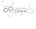
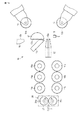
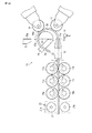
図1は、第1の実施形態に係るコイルばね製造装置1を示している。コイルばね製造装置1は、ばね鋼からなる棒状の材料2を螺旋形に成形することにより、コイルばね3を製造するように構成されている。
FIG. 1 shows a coil
コイルばね3は、材料2を所定のピッチ(一定とは限らない)で螺旋状に成形することによって製造される。コイルばね3の形態は様々であり、例えばコイル径とピッチが巻数位置に応じて変化していてもよい。例えば円筒コイルばねをはじめとして、たる形コイルばね、鼓形コイルばね、テーパコイルばね、不等ピッチコイルばね、マイナスピッチの部分を有するコイルばね等など、様々な形態のコイルばねであってもよい。
The
本実施形態のコイルばね製造装置1は、連続材供給部Wとして機能する連続材載置部4と、直線機(straightener)7と、切断機8(例えばカッティング・グラインダ)と、短尺材載置部9と、ガイド手段として機能するガイドローラ9aと、コイリングマシン10など含んでいる。
The coil
連続材載置部4には、フープ状に巻かれた長尺な材料2(連続材2Aと称す)が載置される。この連続材2Aは、連続材載置部4のリール上に垂直軸まわりに回転可能に載置されている。連続材2Aはフープ材と称されることもあり、巻きが解かれたときの材料2の全長が数百メートル(またはそれ以上)に及ぶことがあり、重さが数トンに及ぶこともある重量物である。
On the continuous
フープ状に巻かれた連続材2Aは、多かれ少なかれ曲り癖がついている。このため連続材2Aから繰り出される材料2は直線機7によって直線状態に矯正される。直線状態に矯正された連続材2Aを切断機8によって所定長さ(例えば数メートル程度)に切断することにより、短尺材2´を得ることができる。切断機8は、直線機7に対して材料2の移動方向下流側に配置されている。切断された短尺材2´は短尺材載置部9の材料架台に載置される。
The
本実施形態(図1)のコイルばね製造装置1において、連続材載置部4上の連続材2Aを用いてコイルばね3を製造する場合、連続材2Aから繰り出される材料2が直線機7によって直線状態に矯正され、さらにガイドローラ9aを経てコイリングマシン10に供給されることにより、コイルばね3が製造される。この場合、連続材2Aから繰り出される材料2は切断機8を素通りして(切断されることなく)、コイリングマシン10に供給される。コイリングマシン10の構成と動作については後に説明する。
In the coil
本実施形態(図1)のコイルばね製造装置1は、連続材載置部4上の連続材2Aから繰り出される材料2を切断機8によって所定長さに切断することにより、短尺材2´を製造することができる。切断された短尺材2´は、短尺材載置部9の材料架台に載置される。短尺材2´を用いてコイルばね3を製造する場合には、短尺材載置部9から短尺材2´を1本ずつコイリングマシン10に供給することにより、コイルばね3が製造される。なお、切断機8とは別の位置に設けた切断装置によって連続材を切断することにより短尺材を製造し、これらの短尺材を短尺材載置部9に載置してもよい。
The coil
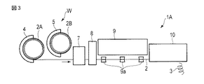
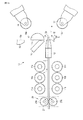
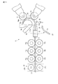
図2は、第2の実施形態に係るコイルばね製造装置1Aを示している。このコイルばね製造装置1Aは、第1の連続材載置部4と、第2の連続材載置部5と、直線機7と、切断機8と、短尺材載置部9と、ガイド手段として機能するガイドローラ9aと、コイリングマシン10などを含んでいる。
FIG. 2 shows a coil
第1の連続材載置部4に、フープ状に巻かれた長尺な材料2からなる第1の連続材2A(第1のフープ材)が載置される。第2の連続材載置部5にもフープ状に巻かれた長尺な材料2からなる第2の連続材2B(第2のフープ材)が載置される。第1の連続材2Aと第2の連続材2Bとは、互いに種類(線径や鋼種)が異なっていてもよいし、互いに同じでもよい。第1の連続材載置部4と第2の連続材載置部5とは、連続材供給部Wとして機能する。
A first
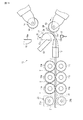
図3は、図2に示されたコイルばね製造装置1Aにおいて、第1の連続材2Aから繰り出される材料2によってコイルばね3が製造される場合を示している。この例では、第1の第1の連続材載置部4上の連続材2Aから繰り出される材料2が直線機7によって直線状態に矯正される。そしてこの材料2がガイドローラ9aを通ってコイリングマシン10に供給され、コイルばね3が製造される。このとき第2の連続材載置部5は使用されないため、この空き時間を利用して所望の線径あるいは鋼種の連続材(フープ材)を第2の連続材載置部5に載置する作業を行うことができる。
FIG. 3 shows a case where the
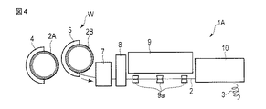
図4は、第2の連続材載置部5上の連続材2Bを用いてコイルばね3が製造される場合を示している。この例では、第2の連続材2Bから繰り出される材料2が直線機7によって直線状態に矯正される。この材料2がガイドローラ9aを通ってコイリングマシン10に供給され、コイルばね3が製造される。このとき第1の連続材載置部4は使用されないため、この空き時間を利用して所望の線径あるいは鋼種の連続材(フープ材)を第1の連続材載置部4に載置する作業を行うことができる。
FIG. 4 shows a case where the
図3に示されるように第1の連続材2Aを用いてコイルばねを量産している状態から、図4に示されるように第2の連続材2Bを用いてコイルばねを量産する状態に切換えることができる。その場合、図3において第1の連続材2Aの供給を停止し、切断機8を用いて第1の連続材2Aを切断する。そののち、図4に示すように第2の連続材載置部5から送られてくる第2の連続材2Bをコイリングマシン10に供給する。
As shown in FIG. 3, the state is switched from the state in which the coil spring is mass-produced using the first
これとは逆に、図4に示されるように第2の連続材2Bを用いてコイルばねを量産している状態から、図3に示されるように第1の連続材2Aを用いてコイルばねを量産する状態に切換えることもできる。その場合、図4において第2の連続材2Bの供給を停止し、切断機8を用いて第2の連続材2Bを切断する。そののち、図3に示すように第1の連続材載置部4から送られてくる第1の連続材2Aをコイリングマシン10に供給する。
On the contrary, from the state in which the coil spring is mass-produced using the second
このように本実施形態のコイルばね製造装置1Aによれば、互いに異なる種類の連続材(第1の連続材2Aと第2の連続材2B)を交互に切換えてコイルばねを製造することができ、使用していない方の連続材載置部の空き時間を利用して材料の準備(段取り作業)を行うことができるため、2種類のコイルばねを能率良く製造するこができる。
Thus, according to the coil
なお、図2に2点鎖線で示すように3台目の連続材載置部6、あるいはそれ以上の連続材載置部を備えていてもよい。これらの連続材載置部を必要に応じて選択使用するとともに、使用していない連続材載置部の空き時間を利用して連続材を準備しておくようにすれば、さらに多くの種類のコイルばねを能率良く製造することができ、多品種のばねの量産に適応することが可能となる。
In addition, you may provide the 3rd continuous
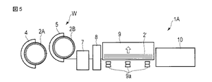
図5は、短尺材2´を製造するための短尺材製造工程を示している。この例では、第2の連続材載置部5から供給される材料2(第2の連続材2B)が直線機7によって直線状態に矯正され、さらに切断機8によって切断されることにより、短尺材2´が製造される。切断された短尺材2´は、短尺材載置部9に載置される。
FIG. 5 shows a short material manufacturing process for manufacturing the short material 2 '. In this example, the material 2 (second
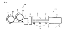
図6は、第1の連続材載置部4上の連続材2Aから繰り出される材料2を用いてコイルばね3が製造されるとともに、第2の連続材載置部5上の連続材2Bから繰り出される材料2によって短尺材2´が製造される場合を示している。この例では、第1の連続材2Aから繰り出される材料2がコイリングマシン10に供給されることにより、コイルばね3が量産される。これと同時に、第2の連続材2Bから繰り出される材料2が切断機8によって所定長さに切断され、短尺材載置部9に載置される。
FIG. 6 shows that the
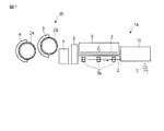
図7は、短尺材載置部9に載置された短尺材2´を用いてコイルばね3が製造される場合を示している。この例では、短尺材載置部9から1本ずつ取出された材料2すなわち短尺材2´がコイリングマシン10に供給され、コイルばね3が製造される。このため短尺材2´の種類に応じた多品種少量のコイルばねの生産に適している。
FIG. 7 shows a case where the
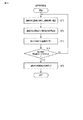
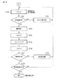
図8は、短尺材製造工程の一例を示すフローチャートである。短尺材製造工程の一例では、第1の連続材2Aまたは第2の連続材2Bを用いて短尺材2´が製造される。例えば図8中のステップST1において、第1の連続材2Aまたは第2の連続材2Bが直線機7に供給され、直線状態に矯正される。
FIG. 8 is a flowchart showing an example of a short material manufacturing process. In an example of the short material manufacturing process, the
ステップST2では、切断機8に供給された連続材が切断機8に所定長さに切断されることにより、短尺材2´が製造される。所定長さに切断された短尺材2´は、ステップST3において短尺材載置部9の材料架台に載置される。そしてステップST4において所定数の短尺材2´がストックされたと判断された場合、ステップST5にて連続材の供給が停止され、短尺材の製造が終了となる。
In step ST2, the continuous material supplied to the cutting
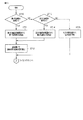
図9と図10は、本実施形態のコイルばね製造装置1Aによってコイルばね3を製造する場合のフローチャートであり、図9は材料を選択する工程を示し、図10はコイリング工程を示している。まず図9中のステップST10において、第1の連続材2Aを用いるか否かが判断され、第1の連続材2Aを用いる場合にはステップST11に移る。ステップST11では、第1の連続材載置部4に置かれている材料2(第1の連続材2A)が直線機7に送られ、ステップST12で直線状態に矯正されたのち、切断機8を素通りしてコイリングマシン10に供給される。
FIGS. 9 and 10 are flowcharts when the
図9中のステップST13では、第2の連続材2Bを用いるか否かが判断される。第2の連続材2Bを用いる場合にはステップST14に移る。ステップST14では、第2の連続材載置部5に置かれている材料2(第2の連続材2B)が直線機7に送られ、ステップST12で直線状態に矯正されたのち、切断機8を素通りしてコイリングマシン10に供給される。
In step ST13 in FIG. 9, it is determined whether or not the second
ステップST13においてコイルばねの材料に短尺材2´を用いると判断された場合にはステップST15に移る。ステップST15では、短尺材載置部9に載置されていた短尺材2´が1本ずつガイドローラ9aを経てコイリングマシン10に供給される。
If it is determined in step ST13 that the short material 2 'is used as the coil spring material, the process proceeds to step ST15. In step ST15, the
図10は、コイリング工程を示すフローチャートである。図10中のステップST20では、コイリングマシン10に送られた材料2(連続材2A,2Bまたは短尺材2´)を用いてコイルばねが製造される。この明細書では、第1の連続材2Aを用いる場合を第1の連続材コイリング工程、第2の連続材2Bを用いる場合を第2の連続材コイリング工程、短尺材2´を用いる場合を短尺材コイリング工程と称している。なお、コイリングマシン10の構成と動作については、後に図11から図21を用いて詳しく説明する。
FIG. 10 is a flowchart showing the coiling process. In Step ST20 in FIG. 10, a coil spring is manufactured using the material 2 (
コイリングマシン10によって成形されたコイルばね3は、図10中のステップST21において形状が検査される。ばね形状が不合格であればステップST22に移り、コイリング条件等が変更されたのち、ステップST20に戻って再びコイリングが行われる。
The shape of the
ステップST21において、ばね形状が合格であると判断された場合には、例えば歪取り焼鈍工程(ステップST23)と、第1のセッチング工程(ステップST24)と、ショットピーニング工程(ステップST25)と、第2のセッチング工程(ステップST26)などが実施される。なお、第1のセッチング工程(ステップST24)と第2のセッチング工程(ステップST26)のいずれか一方のみが行われてもよい。また歪取り焼鈍工程(ステップST23)は、冷間成形によって生じたコイルばねの加工歪を除去する目的で行われ、例えば加熱炉等を用いて加熱される。 If it is determined in step ST21 that the spring shape is acceptable, for example, a strain relief annealing process (step ST23), a first setting process (step ST24), a shot peening process (step ST25), 2 setting process (step ST26) etc. are implemented. Only one of the first setting process (step ST24) and the second setting process (step ST26) may be performed. Further, the strain relief annealing step (step ST23) is performed for the purpose of removing the processing strain of the coil spring generated by the cold forming, and is heated using, for example, a heating furnace.
ステップST27においてばね特性が検査され、ばね特性が合格であればステップST28に移る。ステップST28において所定個数のコイルばねが製造されたと判断された場合にはコイルばね製造が終了となる。所定個数のコイルばねが得られていなければ、ステップST20に戻ってコイルばねの製造が続行される。 In step ST27, the spring characteristic is inspected. If the spring characteristic is acceptable, the process proceeds to step ST28. If it is determined in step ST28 that a predetermined number of coil springs have been manufactured, the coil spring manufacturing is terminated. If the predetermined number of coil springs is not obtained, the process returns to step ST20 and the manufacture of the coil spring is continued.
ステップST27においてばね特性が不合格であると判断されれば、ステップST29に移る。ステップST29では製造条件等が調整され、ステップST20に戻って再びコイリングが行われる。 If it is determined in step ST27 that the spring characteristic is unacceptable, the process proceeds to step ST29. In step ST29, manufacturing conditions and the like are adjusted, and the process returns to step ST20 to perform coiling again.
このように本実施形態は、第1の連続材2Aから繰り出される材料をコイリングマシン10に供給することによりコイルばねを製造する第1の連続材コイリング工程と、第2の連続材2Bから繰り出される材料をコイリングマシン10に供給することによりコイルばねを製造する第2の連続材コイリング工程と、短尺材2´をコイリングマシン10に供給することによりコイルばねを製造する短尺材コイリング工程とを含み、前記第1の連続材コイリング工程と、前記第2の連続材コイリング工程と、前記短尺材コイリング工程とを切換えることにより、各種コイルばねの量産あるいは多品種少量生産を能率良く行うことができる。
As described above, in the present embodiment, the material fed from the first
以下に、コイリングマシン10の構成と動作等について、図11から図21を参照して説明する。
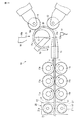
図11は、コイリングマシン10の一部を模式的に表わしている。コイリングマシン10は、コイルばねの材料2を矢印Fで示す方向(材料2の軸線X1に沿う方向)に移動させる複数の材料送りローラ(フィードローラ)11a,11bを備えている。材料送りローラ11a,11bは、図11に示すクランプ位置(材料2を挟む位置)と、図14に示すアンクランプ位置(材料2を解放する位置)とに移動させることができる。
Hereinafter, the configuration and operation of the coiling
FIG. 11 schematically shows a part of the coiling
またコイリングマシン10は、材料2が挿入される材料ガイド12と、材料ガイド12の先端12aから送り出された材料2が最初に接する第1ピン13と、第1ピン13によって曲げられた材料2が接する第2ピン14とを有している。第1ピン13の外周部と第2ピン14の外周部には、それぞれ、周方向に連続する溝13a,14aが形成されている。本実施形態の第1ピン13と第2ピン14とは、それぞれ、軸を中心に回転自在なローラ部材であるが、他の実施形態では、第1ピンと第2ピンとがそれぞれ回転しないピン部材からなるものであってもよい。
In addition, the coiling
またこのコイリングマシン10は、ピッチツール15と、カッティングツール16と、受け刃17aを有するマンドレル17などを有している。ピッチツール15は、第2ピン14に対して材料2の移動方向前側に配置され、第2ピン14によって曲げられた材料2に接することにより、コイルばねのピッチ付けをなすようになっている。カッティングツール16は刃部16aを有し、カッティングツール16がマンドレル17に向かって矢印Z1で示す方向(図11に示す)に移動したときに、刃部16aと受け刃17aとの間で材料2が切断(剪断)される。マンドレル17は、アクチュエータによって第1の位置(図11,図14,図15等に実線で示す上昇位置)と、第2の位置(図16に実線で示す下降位置)とに移動することができる。
The coiling
さらにこのコイリングマシン10は、材料2の先端部2a(図15に示す)の位置を検出する検出手段として機能するセンサ18と、材料2の移動方向に関して材料送りローラ11a,11bの上流側に配置された材料回転装置20とを備えている。材料回転装置20の一例は、ピンチローラユニット21と、ピンチローラユニット21を材料2の軸線X1(図11に示す)回りにねじる回動機構25(図12に示す)とを含んでいる
ピンチローラユニット21は、材料2を径方向から挟みつけるピンチローラ21a,21bと、ピンチローラ21a,21bを材料2の送り方向に回転させるアクチュエータ26(図12に示す)と、ピンチローラ21a,21bを互いに近付ける方向に付勢する押圧機構などを有している。ピンチローラ21a,21bは、図11に2点鎖線で示すクランプ位置V1と、実線で示すアンクランプ位置V2とにわたって移動することができる。
Further, the coiling
第1ピン13は、材料ガイド12の先端12aに対して材料2の移動方向前側(移動方向下流側)に配置されている。第2ピン14は、第1ピン13に対して材料2の移動方向前側に配置されている。材料ガイド12の先端12aから第1ピン13に向かって送り出された材料2は、材料ガイド12の先端12aが実質的な曲げ開始点となって、第1ピン13との間で曲がる。
The
図12は、コイリングマシン10の電気的構成を示すブロック図である。コイリングマシン10は、コントローラとして機能するCPU(Central Processing Unit)40を備えている。このCPU40に、バスライン41を介してROM(Reed Only Memory)42、RAM(Random Access Memory)43、通信インタフェース部44、表示/操作用ドライバ45、材料送り用ドライバ46、第1ピン移動用ドライバ47、第2ピン移動用ドライバ48、ピッチツール用ドライバ49、カッティングツール用ドライバ50、ピンチローラ回転用ドライバ51、マンドレル移動用ドライバ52、回動機構用ドライバ53、センサ18などが接続されている。
FIG. 12 is a block diagram showing an electrical configuration of the coiling
ROM42には、CPU40を制御するためのプログラムや各種の固定的データが格納されている。RAM43は、コイルばねを成形するのに必要な各種データ等が格納されるメモリエリアを備えている。通信インタフェース部44は、通信回線(ネットワーク)を介して外部機器との間で行なうデータ通信を制御する。表示/操作用ドライバ45は、表示部(ディスプレイパネル)を備えた表示操作部55を制御する。表示操作部55を操作することにより、コイルばねの成形に必要な情報をRAM43等のメモリに格納することができる。
The
材料送り用ドライバ46は材料送りローラ11a,11bを回転させるためのモータ60を制御する。第1ピン移動用ドライバ47は、第1ピン13を駆動するためのアクチュエータを備えた第1ピン駆動機構61を制御する。第2ピン移動用ドライバ48は、第2ピン14を駆動するためのアクチュエータを備えた第2ピン駆動機構62を制御する。ピッチツール用ドライバ49は、ピッチツール15を駆動するためのアクチュエータを備えたピッチツール駆動機構63を制御する。カッティングツール用ドライバ50は、カッティングツール16を駆動するためのアクチュエータを備えたカッティングツール駆動機構64を制御する。ピンチローラ回転用ドライバ51は、ピンチローラユニット21のアクチュエータ26を制御する。マンドレル移動用ドライバ52は、マンドレル17を移動(例えば上下方向に移動)させるためのマンドレル移動用アクチュエータ65を制御する。回動機構用ドライバ53は、回動機構25のアクチュエータを制御する。
The
コイリングマシン10のCPU40を含む電気的構成は、材料送りローラ11a,11bの回転動作を制御する制御回路と、第1ピン13および第2ピン14の位置を第1ピン駆動機構61および第2ピン駆動機構62を介して制御する制御回路と、ピッチツール15の位置をピッチツール駆動機構63を介して制御する制御回路と、カッティングツール16の動作をカッティングツール駆動機構64を介して制御する制御回路などを含み、これらはコイリングマシン10の動作等を制御する制御部70として機能する。制御部70は、入力されたコイルばねの形状データ(例えばコイル径)に応じて、第1ピン13と第2ピン14のそれぞれの位置が変化するように、第1ピン駆動機構61と第2ピン駆動機構62を制御する。
The electrical configuration including the
本実施形態の制御部70には、通信インタフェース部44を介してパーソナルコンピュータ80を接続することができる。パーソナルコンピュータ80は、ディスプレイパネルを備えた表示部81と、キーボードを備えた入力操作部82と、マウス等のポインティングデバイス83などを含んでいる。パーソナルコンピュータ80は、必要に応じて着脱可能な記憶媒体84を備えている。
A
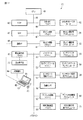
以下に、コイルばねの成形を開始する際に最初に行われる材料2の先端部2aを成形する作業(先端部整形作業)について、図13から図21を参照して説明する。この先端部整形作業は、制御部70に格納されたコンピュータプログラムと、制御用の形状データとに基づいて、CPU40によって自動化されている。
Below, the operation | work (tip | end part shaping operation | work) which shape | molds the front-end | tip
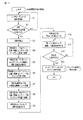
図13は、制御部70に格納されているコンピュータプログラムの機能の一例を示すフローチャートである。このコンピュータプログラムは、コイルばねの先端部整形作業を行う際に起動される。しかし状況によっては、先端部整形作業の一部を作業員がマニュアル操作により行ってもよい。
FIG. 13 is a flowchart illustrating an example of functions of a computer program stored in the
図14は、材料2が供給される前のコイリングマシン10を示している。材料送りローラ11a,11bは、材料2の移動を妨げないように、上下方向に互いに離れた位置(アンクランプ位置)にて待機している。
FIG. 14 shows the coiling
図13中のステップS1では、材料2がピンチローラ21a,21bによって材料ガイド12に向けて移動することにより、先端部2aが第1ピン13に向かって前進する。このときピンチローラ21a,21bは、クランプ位置に移動している。材料送りローラ11a,11bは、アンクランプ位置に移動している。材料2がピンチローラ21a,21bによって材料ガイド12に向かって前進すると、例えば図15に示されるように、材料2の先端部2aが材料ガイド12の先端12aから突き出る。
In step S <b> 1 in FIG. 13, the
図13中のステップS2では、先端部2aが所定位置に達したか否かが判定される。先端部2aが所定位置に達していなければステップS1に戻り、材料2がさらに前進する。例えば検出手段(センサ18)によって材料2の先端部2aが検出されると、ステップS3に移行し、材料2の移動が停止する。このとき材料2の先端部2aが材料ガイド12の先端12aから所定距離L1だけ突き出た位置で停止してもよい。
In step S2 in FIG. 13, it is determined whether or not the
図13中のステップS4では、材料送りローラ11a,11bがクランプ位置に移動することにより、材料2が材料送りローラ11a,11b間に挟まれるとともに、ピンチローラ21a,21bがアンクランプ位置に移動する。このため材料2は材料送りローラ11a,11bによって移動することになる。
In step S4 in FIG. 13, the
ステップS5では、図16に示されるように材料送りローラ11a,11b間に挟まれた材料2が第1ピン13に向かって移動し、材料2の先端部2aが第1ピン13に到達した状態において第1ピン13が駆動されることにより、先端部2aが第1ピン13によって曲げられる。たとえば材料2の先端部2aが第1ピン13によって、マンドレル17に近づく方向に曲げられる。このときマンドレル17は、図16に2点鎖線で示す第1の位置から矢印Z2で示す方向に移動することにより、マンドレル17の下面が材料ガイド12の先端12aの直近の第2の位置に切換わる。そして材料2の先端部2aが第1ピン13によって曲げられたのち、マンドレル17が再び第1の位置(図16に2点鎖線で示す)に移動する。
In step S5, as shown in FIG. 16, the
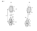
図17(A)に示すように、第1ピン13と第2ピン14との位置が、ピンの軸線X2,X3に沿う方向に距離G分だけずれている場合、この状態のまま材料2の先端部2aを第2ピン14に向かって前進させると、材料2の先端部2aが第2ピン14の溝14aから外れてしまうことがある。特に第1ピン13と第2ピン14との間の距離L2が大きくなるほど、先端部2aが第2ピン14の溝14aから外れやすくなる。
As shown in FIG. 17A, when the positions of the
また図17(B)に示すように、第2ピン14が第1ピン13の前方に角度θ3をなして傾いていることもある。この場合も材料2の先端部2aを前進させると、材料2の先端部2aが第2ピン14の溝14aから外れてしまうことがある。このため従来は、作業者が治具等によって材料2の先端部2aの向きを矯正する必要があった。
In addition, as shown in FIG. 17B, the
本実施形態の場合、図16に示されるように材料2の先端部2aが第1ピン13によって曲げられかつ第2の位置(2点鎖線に示す)に移動した状態において、ピンチローラ21a,21bによって挟まれている材料2を軸線X1回りに回転させる。このとき材料2の先端部2aは、第1ピン13と第2ピン14との間に位置している。
In the case of the present embodiment, as shown in FIG. 16, the
図13中のステップS6では、材料送りローラ11a,11bがアンクランプ位置(図16に2点鎖線Yで示す)に移動し、かつ、ピンチローラ21a,21bがクランプ位置に移動する。この状態のもとで材料回転装置20を駆動することにより、材料2の先端部2aが第2ピン14の溝14aの方向を向くようにピンチローラユニット21が回動する(ステップS7)。
In step S6 in FIG. 13, the
材料2が軸線X1回りに回動することにより、図18に示すように材料2の先端部2aが角度θだけ傾く。これにより、材料2の先端部2aが第1ピン13から第2ピン14に向かって移動したときに、先端部2aを第2ピン14の溝14aに入れることができるようになる。
By rotating the
図13中のステップS8において、材料送りローラ11a,11bがクランプ位置に移動し、かつ、ピンチローラ21a,21bがアンクランプ位置に移動する。そして材料送りローラ11a,11bが回転し、材料2が前進することにより(ステップS9)、先端部2aが第2ピン14の溝14aに入る(ステップS10)。
In step S8 in FIG. 13, the
図19に示すように材料送りローラ11a,11bによって材料2をさらに移動させることにより、材料2の先端部2aを第2ピン14とマンドレル17との間に位置させる。そして材料2を移動させながら、第1ピン13と第2ピン14を駆動し、先端部2aを第1ピン13と第2ピン14との間で曲げることによって、図20に示すように先端側円弧部2b´を形成する(図13中のステップS11とS12)。
As shown in FIG. 19, the
所定形状の先端側円弧部2b´が形成されたら、図21に示すようにカッティングツール16を受け刃17aに向かって移動させることによって、先端側のスクラップ部2xを切り落とす(図13中のステップS13)。この切断作業(ステップS13)は、場合によっては作業者が状況を確認し、異常がなければマニュアル操作によりボタン等のスイッチを操作することにより、カッティングツール16を動作させてスクラップ部2xを切断することもある。以上の一連の工程を経ることにより、コイルばね1の先端部整形作業が終了する。
When the tip-
スクラップ部2xが切り落とされると先端側円弧部2b´が残る。この先端側円弧部2b´はコイルばねの一部(座巻部)となる。これ以降は、材料送りローラ11a,11bによって材料2を連続的に移動させることにより、コイルばね1の成形(コイリング)を行う。すなわち、材料ガイド12の先端12aから第1ピン13を経て第2ピン14に向けて移動する材料2が、第1ピン13と第2ピン14とによって円弧状に成形されることにより、図11に示されるように円弧部2bが連続的に形成される。
When the
円弧部2bの曲率半径は、第1ピン13と第2ピン14との間で最小になったあと、スプリングバックの影響により、ピッチツール15に近付くにつれて曲率半径が少しずつ増加してゆく。このためスプリングバックの影響を考慮して第2ピン14等の位置が制御される。こうして1個分のコイルばねが成形されたら、カッティングツール16が作動することによりコイルばねの後端(次に成形されるコイルばねの前端)が切断される。第1の連続材2Aあるいは第2の連続材2B等の連続材を用いる場合には、次の1個分のコイルばねの成形が連続して行われる。短尺材2´を用いる場合には、短尺材2´の長さに応じた数(例えば1個分)のコイルばねが成形される。
After the radius of curvature of the
以上説明したように本実施形態のコイルばねの先端部整形方法は、制御部70によって自動化された下記の工程を含んでいる。
(1)材料2を材料ガイド12に向かって移動させ、
(2)材料ガイド12から送り出された材料2の先端部2aの位置を検出し、
(3)マンドレル17を第2の位置に移動させ、
(4)先端部2aを第1ピン13によってマンドレル17に近付ける方向に曲げ、
(5)マンドレル17を第1の位置に移動させ、
(6)材料送りローラ11a,11bをアンクランプ位置に移動させ、
(7)材料2の先端部2aが第2ピン14の溝14aに向かうように材料2を軸線X1回りに回動させ、
(8)材料送りローラ11a,11bをクランプ位置に移動させ、
(9)材料送りローラ11a,11bによって材料2を移動させることにより、先端部2aを第2ピン14の溝14aに入れ、
(10)材料2を第1ピン13と第2ピン14との間で曲げることによって先端側円弧部2b´を形成し、
(11)先端側円弧部2b´から先のスクラップ部2xをカッティングツール16によって切り落とす。
As described above, the coil spring tip shaping method of the present embodiment includes the following steps automated by the
(1) Move
(2) Detect the position of the
(3) Move the
(4) The
(5) Move the
(6) Move the
(7) The
(8) Move the
(9) By moving the
(10) Forming the distal end
(11) Cut off the
なお本発明を実施するに当たって、フープ材等の連続材を載置する連続材載置部や短尺材載置部、直線機、切断機をはじめとして、コイルばね製造装置を構成する要素の構造や配置等の態様を必要に応じて種々に変更して実施できることは言うまでもない。例えば材料をコイリングマシンに導くガイド手段は、ガイドローラ9a以外の形態のガイド部材を用いてもよい。また第1ピンや第2ピン、ピッチツール、カッティングツールなどコイリングマシンの構成要素についても必要に応じて種々に変更して実施できることは言うまでもない。
In carrying out the present invention, the structure of the elements constituting the coil spring manufacturing apparatus, such as a continuous material placing part for placing a continuous material such as a hoop material, a short material placing part, a linear machine, and a cutting machine, Needless to say, the arrangement and the like can be variously changed as necessary. For example, the guide means for guiding the material to the coiling machine may use a guide member other than the
1,1A…コイルばね製造装置、2…材料、W…連続材供給部、2A…第1の連続材、2B…第2の連続材、2´…短尺材、3…コイルばね、4…第1の連続材載置部、5…第2の連続材載置部、6…第3の連続材載置部、7…直線機、8…切断機、9…短尺材載置部、9a…ガイドローラ(ガイド手段)、10…コイリングマシン、11a,11b…材料送りローラ、12…材料ガイド、12a…材料ガイドの先端、13…第1ピン、13a…溝、14…第2ピン、14a…溝、15…ピッチツール、16…カッティングツール、17…マンドレル、18…センサ(検出手段)、20…材料回転装置、21…ピンチローラユニット、21a,21b…ピンチローラ、70…制御部。
DESCRIPTION OF
Claims (4)
フープ状に巻かれた連続材から繰り出される材料を前記コイリングマシンに供給する連続材供給部と、
前記連続材供給部と前記コイリングマシンとの間に配置され前記連続材から繰り出される前記材料を直線状態に矯正する直線機と、
前記直線機に対して前記材料の移動方向下流側に配置され、前記材料を切断する切断機と、
所定長さに切断された短尺材を載置する短尺材載置部と、
前記連続材供給部から繰り出された前記材料または前記短尺材載置部から取り出された短尺材を前記コイリングマシンに供給するガイド手段と、
を具備したことを特徴とするコイルばね製造装置。 A coiling machine,
A continuous material supply unit that supplies the coiling machine with a material fed from a continuous material wound in a hoop shape;
A linear machine that is arranged between the continuous material supply unit and the coiling machine and corrects the material fed from the continuous material into a linear state;
A cutting machine that is disposed downstream of the linear machine in the moving direction of the material and cuts the material;
A short material placing portion for placing a short material cut into a predetermined length;
A guide means for supplying the coiling machine with the material fed out from the continuous material supply unit or the short material taken out from the short material placing unit;
A coil spring manufacturing apparatus comprising:
前記材料を移動させる材料送りローラと、
前記材料が挿入される材料ガイドと、
前記材料ガイドの先端から送り出された前記材料が接する第1ピンと、
前記第1ピンに対し前記材料の移動方向前側に配置され、前記第1ピンとの間で前記材料を曲げることにより前記第1ピンとの間に円弧部を形成する第2ピンと、
前記第2ピンに対し材料の移動方向前側に配置され前記材料が接するピッチツールと、
前記第2ピンと前記ピッチツールとの間に配置され、マンドレルとの間で前記材料を切断するカッティングツールと、
前記材料の先端部整形作業を自動化する制御部を有し、
該制御部が、
前記材料の先端部を前記第1ピンに向かって前進させる手段と、
前記材料の先端部の位置を検出する検出手段と、
前記先端部が前記第1ピンに到達した状態において前記先端部を第1ピンによってマンドレルに近付ける方向に曲げる手段と、
前記先端部を前記第1ピンと前記第2ピンとの間で曲げることによって先端側円弧部を形成する手段と、
を具備したことを特徴とする請求項1または2に記載のコイルばね製造装置。 The coiling machine
A material feed roller for moving the material;
A material guide into which the material is inserted;
A first pin that contacts the material fed from the tip of the material guide;
A second pin that is disposed on the front side in the movement direction of the material with respect to the first pin, and that forms an arc portion with the first pin by bending the material with the first pin;
A pitch tool disposed on the front side in the movement direction of the material with respect to the second pin and in contact with the material;
A cutting tool disposed between the second pin and the pitch tool and cutting the material between a mandrel;
Having a control unit that automates the tip shaping operation of the material,
The control unit
Means for advancing the tip of the material toward the first pin;
Detection means for detecting the position of the tip of the material;
Means for bending the tip portion toward the mandrel by the first pin in a state where the tip portion reaches the first pin;
Means for forming a tip side arc portion by bending the tip portion between the first pin and the second pin;
The coil spring manufacturing apparatus according to claim 1 or 2, characterized by comprising:
第2の連続材載置部に載置されたフープ状の第2の連続材から繰り出される材料を前記コイリングマシンに供給しコイルばねを製造する第2の連続材コイリング工程と、
前記第1の連続材または前記第2の連続材を所定長さに切断することにより短尺材を製造する短尺材製造工程と、
前記短尺材を前記コイリングマシンに供給しコイルばねを製造する短尺材コイリング工程とを含み、
前記第1の連続材コイリング工程と、前記第2の連続材コイリング工程と、前記短尺材コイリング工程とを切換えることにより複数種類のコイルばねを製造することを特徴とするコイルばねの製造方法。 A first continuous material coiling step of manufacturing a coil spring by supplying a coiling machine with a material fed from a hoop-shaped first continuous material placed on the first continuous material placement unit;
A second continuous material coiling step of manufacturing a coil spring by supplying a material fed from a hoop-shaped second continuous material placed on the second continuous material placement unit to the coiling machine;
A short material manufacturing process for manufacturing a short material by cutting the first continuous material or the second continuous material into a predetermined length;
A short material coiling step of supplying the short material to the coiling machine and manufacturing a coil spring,
A method of manufacturing a coil spring, wherein a plurality of types of coil springs are manufactured by switching between the first continuous material coiling step, the second continuous material coiling step, and the short material coiling step.
Priority Applications (5)
| Application Number | Priority Date | Filing Date | Title |
|---|---|---|---|
| JP2015113849A JP6571994B2 (en) | 2015-06-04 | 2015-06-04 | Coil spring manufacturing apparatus and coil spring manufacturing method |
| CN201680030537.XA CN107614145B (en) | 2015-06-04 | 2016-04-11 | Coil spring manufacturing device and coil spring manufacturing method |
| PCT/JP2016/061705 WO2016194482A1 (en) | 2015-06-04 | 2016-04-11 | Device for manufacturing coil spring and method for manufacturing coil spring |
| EP16802919.7A EP3305433A4 (en) | 2015-06-04 | 2016-04-11 | Device for manufacturing coil spring and method for manufacturing coil spring |
| US15/818,316 US20180071812A1 (en) | 2015-06-04 | 2017-11-20 | Device for manufacturing coil spring and method for manufacturing coil spring |
Applications Claiming Priority (1)
| Application Number | Priority Date | Filing Date | Title |
|---|---|---|---|
| JP2015113849A JP6571994B2 (en) | 2015-06-04 | 2015-06-04 | Coil spring manufacturing apparatus and coil spring manufacturing method |
Publications (2)
| Publication Number | Publication Date |
|---|---|
| JP2017001038A true JP2017001038A (en) | 2017-01-05 |
| JP6571994B2 JP6571994B2 (en) | 2019-09-04 |
Family
ID=57441099
Family Applications (1)
| Application Number | Title | Priority Date | Filing Date |
|---|---|---|---|
| JP2015113849A Active JP6571994B2 (en) | 2015-06-04 | 2015-06-04 | Coil spring manufacturing apparatus and coil spring manufacturing method |
Country Status (5)
| Country | Link |
|---|---|
| US (1) | US20180071812A1 (en) |
| EP (1) | EP3305433A4 (en) |
| JP (1) | JP6571994B2 (en) |
| CN (1) | CN107614145B (en) |
| WO (1) | WO2016194482A1 (en) |
Cited By (1)
| Publication number | Priority date | Publication date | Assignee | Title |
|---|---|---|---|---|
| TWI692335B (en) * | 2018-09-07 | 2020-05-01 | 黃賢德 | Machine for making variable-pressure coil spring of curtain spring motor |
Families Citing this family (2)
| Publication number | Priority date | Publication date | Assignee | Title |
|---|---|---|---|---|
| JP7258545B2 (en) | 2018-12-28 | 2023-04-17 | 日本発條株式会社 | Coiling machine and manufacturing method of coil spring |
| CN112872251B (en) * | 2020-12-24 | 2023-05-16 | 东莞市杜氏诚发精密弹簧有限公司 | Rotary wire type spring forming machine with automatic wire feeding mechanism |
Citations (5)
| Publication number | Priority date | Publication date | Assignee | Title |
|---|---|---|---|---|
| JPS58135743A (en) * | 1982-02-08 | 1983-08-12 | Hitachi Ltd | Automatic treating device of wire rod |
| JPH05138277A (en) * | 1991-11-18 | 1993-06-01 | Tokyo Koiringu Mach Seisakusho:Kk | Manufacture of coil spring |
| JPH081267A (en) * | 1994-06-22 | 1996-01-09 | Daido Steel Co Ltd | Production of spring material and production of spring |
| JPH11123497A (en) * | 1997-10-15 | 1999-05-11 | Daido Steel Co Ltd | Work feeding device for warm/hot working machine |
| JP2013226584A (en) * | 2012-04-26 | 2013-11-07 | Nhk Spring Co Ltd | Control device for coiling machine, and method for manufacturing coil spring |
Family Cites Families (9)
| Publication number | Priority date | Publication date | Assignee | Title |
|---|---|---|---|---|
| JPH03189036A (en) * | 1989-12-19 | 1991-08-19 | Kobe Steel Ltd | Manufacture of tapered coil spring |
| DE4229294C1 (en) * | 1992-09-02 | 1993-12-16 | Wafios Maschinen Wagner | Wire-shaping machine esp. for mfr. of springs - has wire-clamping rollers turning in either direction together round the wire guide axis and intermittently and programme-controlled |
| DE19748133C2 (en) * | 1997-10-31 | 2000-06-29 | Wafios Maschinen Wagner | Method and device for automatic winding of straight wire to coiled compression springs |
| DE29822163U1 (en) * | 1998-12-11 | 1999-02-11 | Minyu Machinery Corp | Device for the production of wire products |
| US6910360B2 (en) * | 2001-10-23 | 2005-06-28 | L&P Property Management Company | Multiple wire feed for spring coiling machine and method |
| JP4010829B2 (en) * | 2002-02-21 | 2007-11-21 | 中央発條株式会社 | Coil spring manufacturing method and apparatus |
| JP2004025246A (en) * | 2002-06-26 | 2004-01-29 | Nhk Spring Co Ltd | Method for manufacturing coiled spring having straight inclined axis |
| KR101075323B1 (en) * | 2009-05-19 | 2011-10-19 | 대원강업주식회사 | Manufacturing method of coil spring using helicoid reduction mill |
| DE102013207028B3 (en) * | 2013-04-18 | 2014-06-26 | Wafios Ag | Spring coiling machine with adjustable cutting device |
-
2015
- 2015-06-04 JP JP2015113849A patent/JP6571994B2/en active Active
-
2016
- 2016-04-11 CN CN201680030537.XA patent/CN107614145B/en not_active Expired - Fee Related
- 2016-04-11 EP EP16802919.7A patent/EP3305433A4/en not_active Withdrawn
- 2016-04-11 WO PCT/JP2016/061705 patent/WO2016194482A1/en active Application Filing
-
2017
- 2017-11-20 US US15/818,316 patent/US20180071812A1/en not_active Abandoned
Patent Citations (5)
| Publication number | Priority date | Publication date | Assignee | Title |
|---|---|---|---|---|
| JPS58135743A (en) * | 1982-02-08 | 1983-08-12 | Hitachi Ltd | Automatic treating device of wire rod |
| JPH05138277A (en) * | 1991-11-18 | 1993-06-01 | Tokyo Koiringu Mach Seisakusho:Kk | Manufacture of coil spring |
| JPH081267A (en) * | 1994-06-22 | 1996-01-09 | Daido Steel Co Ltd | Production of spring material and production of spring |
| JPH11123497A (en) * | 1997-10-15 | 1999-05-11 | Daido Steel Co Ltd | Work feeding device for warm/hot working machine |
| JP2013226584A (en) * | 2012-04-26 | 2013-11-07 | Nhk Spring Co Ltd | Control device for coiling machine, and method for manufacturing coil spring |
Cited By (1)
| Publication number | Priority date | Publication date | Assignee | Title |
|---|---|---|---|---|
| TWI692335B (en) * | 2018-09-07 | 2020-05-01 | 黃賢德 | Machine for making variable-pressure coil spring of curtain spring motor |
Also Published As
| Publication number | Publication date |
|---|---|
| CN107614145B (en) | 2019-12-27 |
| EP3305433A1 (en) | 2018-04-11 |
| US20180071812A1 (en) | 2018-03-15 |
| JP6571994B2 (en) | 2019-09-04 |
| CN107614145A (en) | 2018-01-19 |
| EP3305433A4 (en) | 2019-01-23 |
| WO2016194482A1 (en) | 2016-12-08 |
Similar Documents
| Publication | Publication Date | Title |
|---|---|---|
| EP3151985B1 (en) | Bending machine and corresponding method | |
| US8393191B2 (en) | Wire forming apparatus | |
| JP6420690B2 (en) | Coiling machine and coil spring manufacturing method | |
| JP6571994B2 (en) | Coil spring manufacturing apparatus and coil spring manufacturing method | |
| KR102189749B1 (en) | Drawing and Straightening Apparatus for Metal Wire, and Corresponding Drawing and Straightening Method | |
| CN103781570A (en) | Method for producing springs and spring machine for carrying out the method | |
| JP6012244B2 (en) | COILING MACHINE CONTROL DEVICE AND COIL SPRING MANUFACTURING METHOD | |
| JP2010052002A (en) | Bending apparatus and bending method | |
| JP5680912B2 (en) | Toroidal coil manufacturing equipment | |
| CN111225753B (en) | Machine and method for bending elongated elements, preferably metal, such as bars, rods, profiles and the like | |
| JP6450640B2 (en) | Coiling machine and coil spring manufacturing method | |
| TWI658881B (en) | Coil spring manufacturing device and method | |
| JP2016159314A (en) | Coil spring manufacturing device and coil spring manufacturing method | |
| EP0209876A2 (en) | Universal bending machine and respective method for bending | |
| JP2005188064A (en) | Automatic binding equipment for reinforcement grating | |
| JP2011110569A (en) | Straightening device and straightening method for coil-shaped wire rod | |
| JP5505823B2 (en) | Bending device and bending method | |
| JP3838451B2 (en) | Tube bending equipment | |
| JP2018130737A (en) | Pipe bender | |
| JP2000288635A (en) | U-bending method by means of bending roll | |
| JP3776411B2 (en) | Coil winding bender | |
| JP2002273536A (en) | Coiling apparatus and method, and core of coiling apparatus | |
| KR20000042211A (en) | Uncoiler able to continuously supply coils | |
| KR20220152395A (en) | bending machine |
Legal Events
| Date | Code | Title | Description |
|---|---|---|---|
| A621 | Written request for application examination |
Free format text: JAPANESE INTERMEDIATE CODE: A621 Effective date: 20180208 |
|
| A131 | Notification of reasons for refusal |
Free format text: JAPANESE INTERMEDIATE CODE: A131 Effective date: 20190226 |
|
| A521 | Request for written amendment filed |
Free format text: JAPANESE INTERMEDIATE CODE: A523 Effective date: 20190424 |
|
| TRDD | Decision of grant or rejection written | ||
| A01 | Written decision to grant a patent or to grant a registration (utility model) |
Free format text: JAPANESE INTERMEDIATE CODE: A01 Effective date: 20190716 |
|
| A61 | First payment of annual fees (during grant procedure) |
Free format text: JAPANESE INTERMEDIATE CODE: A61 Effective date: 20190809 |
|
| R150 | Certificate of patent or registration of utility model |
Ref document number: 6571994 Country of ref document: JP Free format text: JAPANESE INTERMEDIATE CODE: R150 |
|
| R250 | Receipt of annual fees |
Free format text: JAPANESE INTERMEDIATE CODE: R250 |
|
| R250 | Receipt of annual fees |
Free format text: JAPANESE INTERMEDIATE CODE: R250 |