JP2017000978A - Apparatus-containment device - Google Patents
Apparatus-containment device Download PDFInfo
- Publication number
- JP2017000978A JP2017000978A JP2015119014A JP2015119014A JP2017000978A JP 2017000978 A JP2017000978 A JP 2017000978A JP 2015119014 A JP2015119014 A JP 2015119014A JP 2015119014 A JP2015119014 A JP 2015119014A JP 2017000978 A JP2017000978 A JP 2017000978A
- Authority
- JP
- Japan
- Prior art keywords
- front opening
- work space
- work
- case
- mounting table
- Prior art date
- Legal status (The legal status is an assumption and is not a legal conclusion. Google has not performed a legal analysis and makes no representation as to the accuracy of the status listed.)
- Granted
Links
- 239000003814 drug Substances 0.000 description 12
- 239000000843 powder Substances 0.000 description 12
- 239000002775 capsule Substances 0.000 description 11
- 229940079593 drug Drugs 0.000 description 11
- 239000000126 substance Substances 0.000 description 11
- 239000000463 material Substances 0.000 description 6
- 238000002474 experimental method Methods 0.000 description 5
- 239000007789 gas Substances 0.000 description 5
- 125000002066 L-histidyl group Chemical group [H]N1C([H])=NC(C([H])([H])[C@](C(=O)[*])([H])N([H])[H])=C1[H] 0.000 description 3
- 229910052782 aluminium Inorganic materials 0.000 description 3
- XAGFODPZIPBFFR-UHFFFAOYSA-N aluminium Chemical compound [Al] XAGFODPZIPBFFR-UHFFFAOYSA-N 0.000 description 3
- 239000002699 waste material Substances 0.000 description 3
- 238000013459 approach Methods 0.000 description 2
- 239000002928 artificial marble Substances 0.000 description 2
- 239000000428 dust Substances 0.000 description 2
- 229910052751 metal Inorganic materials 0.000 description 2
- 239000002184 metal Substances 0.000 description 2
- 239000007769 metal material Substances 0.000 description 2
- 239000005341 toughened glass Substances 0.000 description 2
- 241000894006 Bacteria Species 0.000 description 1
- BZHJMEDXRYGGRV-UHFFFAOYSA-N Vinyl chloride Chemical compound ClC=C BZHJMEDXRYGGRV-UHFFFAOYSA-N 0.000 description 1
- 239000011248 coating agent Substances 0.000 description 1
- 238000000576 coating method Methods 0.000 description 1
- 238000006073 displacement reaction Methods 0.000 description 1
- 239000003517 fume Substances 0.000 description 1
- 239000011521 glass Substances 0.000 description 1
- 238000003780 insertion Methods 0.000 description 1
- 230000037431 insertion Effects 0.000 description 1
- 238000004519 manufacturing process Methods 0.000 description 1
- 238000005259 measurement Methods 0.000 description 1
- 244000005700 microbiome Species 0.000 description 1
- 229920003023 plastic Polymers 0.000 description 1
- 238000012545 processing Methods 0.000 description 1
- 238000007789 sealing Methods 0.000 description 1
- 239000002341 toxic gas Substances 0.000 description 1
- 239000013585 weight reducing agent Substances 0.000 description 1
Images


Abstract
Description
本発明は、例えば有害物を排気する機器を使用する際に、この機器を作業空間の雰囲気内に封じ込めるための機器封じ込め装置に関する。 The present invention relates to a device containment device for containing, for example, a device for exhausting harmful substances in an atmosphere of a work space.
ドラフトチャンバのような機器封じ込め装置は、有害物を排気する対象の機器を作業空間の雰囲気内に封じ込めるために使用される。この対象の機器は、作業空間の雰囲気内に封じ込めることで、機器封じ込め装置が置かれている空間から機器を隔離することで、作業者や居室空間が有害物の影響を受けないようにする。 Equipment containment devices such as draft chambers are used to contain equipment to be evacuated of harmful substances in the atmosphere of the work space. By enclosing the target device in the atmosphere of the work space, the device and the room space are not affected by harmful substances by isolating the device from the space where the device containment device is placed.
特許文献1は、手腕挿入開口可動式フードを有するドラフトチャンバを開示している。このドラフトチャンバは、作業空間の前面開口を、透明なガラスの開閉扉で開閉できる。有害物を排気する対象の機器は、ドラフトチャンバ内のテーブルに置かれている。そして、作業者がこの開閉扉を開き、開閉扉の開いた前面開口から作業者が手腕を挿入して、機器を取り扱うようになっている。
機器を取り扱うために、作業者が前面開口から作業空間内に手腕を挿入する場合にも、作業空間から有害な気体や細菌等が外部に漏れ出ないように、作業空間の空気を排気して、作業空間の気圧が外気より低くなるようにしている。 Even when an operator inserts his / her hand into the work space from the front opening to handle the equipment, exhaust the work space air so that harmful gases and bacteria do not leak out of the work space. The air pressure in the work space is made lower than the outside air.
近年、作業者の作業環境の改善の意識が高まりつつあり、特に企業においてはレギュレーションにより厳密性が高まり、対象の機器をある作業空間の雰囲気内に封じ込める新たなニーズが期待できる。 In recent years, workers are becoming more conscious of improving their work environment, and in particular, companies are becoming more strict due to regulations, and new needs can be expected to contain target equipment in the atmosphere of a certain work space.
ところで、作業者が、特許文献1に記載のドラフトチャンバは、被処理物の秤量や被処理物の小分け作業を行う目的としたものであり、ドラフトチャンバ内に入れる機器は、比較的小型であり、機器を作業空間内に搬入したり、作業空間内で機器を用いて作業をする際の作業性を考慮したものではない。すなわち、従来のドラフトチャンバは、被処理物の秤量や被処理物の小分け作業を行うことを前提にして、作業性を確保したり、ハンドリングスペースを確保している。
By the way, the draft chamber described in
しかし、従来のドラフトチャンバ内で、天秤等に比べて比較的大型の機器、例えば分析機器等を用いたいという要請がある。この較的大型の分析機器を用いる作業としては、分析サンプルのセッティング作業が重要である。分析機器は比較的大型であり、ドラフトチャンバ内に収容するのは容易ではなく、作業者が立った姿勢で分析サンプルのセッティング作業を行うことは、考慮されていない。 However, there is a demand for using a relatively large device such as an analytical device in a conventional draft chamber as compared with a balance or the like. As work using this comparatively large analytical instrument, setting work of an analysis sample is important. The analytical instrument is relatively large and is not easy to be accommodated in the draft chamber, and it is not considered that the operator sets the analysis sample in a standing posture.
本発明は、上記に鑑みてなされたもので、その目的とするところは、作業者が、対象となる比較的大型の機器を、作業空間の雰囲気内に封じ込めた状態で、安全にかつ容易に作業を行うことができる機器封じ込め装置を提供することにある。 The present invention has been made in view of the above, and an object of the present invention is to allow a worker to safely and easily enclose a relatively large target device in an atmosphere of a work space. An object of the present invention is to provide a device containment device capable of performing work.
上記課題を達成するため、請求項1に記載の機器封じ込め装置は、閉鎖された本体の作業空間内で作業を行う機器を外気に対して封じ込めるための機器封じ込め装置であって、前記本体は、前記作業空間を形成しており上部と下部を有するケース部と、前記ケース部の前記下部の前記作業空間内に配置されて、前記機器を載せるための載置台と、前記機器を前記作業空間内に搬入するために開閉可能な機器搬入用の開口領域部と、を備えることを特徴とする。
In order to achieve the above object, the device containment device according to
請求項1に記載の機器封じ込め装置では、機器は、機器搬入用の前面若しくは側面の開口領域部を開けた状態で、ケース部の下部にある載置台に載せることができ、機器を載置台に載せた後は、機器搬入用の当該開口領域部を閉じることで、ケース部は外気に対して閉鎖できる。このため、作業者が、対象の機器が大型であっても、機器を作業空間の雰囲気内に封じ込めた状態で、安全にかつ容易に作業を行うことができる。また、機器は、ケース部の下部にある載置台に載せるので、比較的大型の機器であっても、ケース部内に収めることができ、使用者は、機器を立ち姿勢で操作することができる。
In the device containment apparatus according to
請求項2に記載の機器封じ込め装置では、前記ケース部の前記上部には、前記上部の作業空間に対応する位置に、第1前面開口部分が設けられ、前記第1前面開口部分は、前面扉により開閉可能により覆われ、前記ケース部の前記下部には、前記下部の作業空間に対応する位置に、第2前面開口部分が設けられ、前記第2前面開口部分は、閉鎖部材により開閉可能により覆われ、前記機器搬入用の前面開口領域部は、前記第1前面開口部分と前記第2前面開口部分から形成されることを特徴とする。
The device containment apparatus according to
請求項2に記載の機器封じ込め装置では、第1前面開口部分と第2前面開口部分から形成される機器搬入用の前面開口領域部を開けることにより、大型の機器であっても、載置台に載せた状態で、ケース部内に収容することができる。重量のある大型の機器であっても、載置台上をスライドさせながら載置台上の所定の位置に設定することができ、作業者は、対象とする機器をケース部内に収容する作業を容易に行うことができる。
In the device containment apparatus according to
請求項3に記載の機器封じ込め装置では、前記ケース部の前記上部の作業空間内に配置される補助作業台を備え、前記補助作業台は、前記機器の上部分を通して前記補助作業台の上方に突出させるための通し用の開口部分を有することを特徴とする。
The device containment apparatus according to
請求項3に記載の機器封じ込め装置では、必要に応じて、ケース部の前記上部の作業空間内には、補助作業台を配置することができるので、作業に必要な器具などを載せることができる。この場合に、補助作業台は、通し用の開口部分を有しており、機器が大型で上方に突き出た上部分があっても、この機器の上部分は補助作業台の通し用の開口部分に通すことで、機器が補助作業台に干渉しない。作業者は、例えば立ち姿勢で上部分の作業空間での作業を行うことができる。 In the device containment apparatus according to the third aspect, an auxiliary work table can be disposed in the upper work space of the case portion as necessary, so that tools necessary for work can be placed. . In this case, the auxiliary workbench has a through opening, and even if the equipment is large and has an upper part protruding upward, the upper part of this equipment is the open part of the auxiliary worktable. By passing through, the equipment does not interfere with the auxiliary workbench. For example, the worker can perform work in the upper work space in a standing posture.
請求項4に記載の機器封じ込め装置では、前記作業空間内は、低風量で排気されることを特徴とする。 In the device containment apparatus according to a fourth aspect of the present invention, the work space is exhausted with a low air volume.
請求項4に記載の機器封じ込め装置では、低風量で、作業空間内に有害ガス等を封じ込めておくことができるので、省エネルギー化が図れる。 In the device containment apparatus according to the fourth aspect of the present invention, it is possible to conserve toxic gas or the like in the work space with a low air volume, so that energy saving can be achieved.
本発明によれば、作業者が、対象となる比較的大型の機器を、作業空間の雰囲気内に封じ込めた状態で、安全にかつ容易に作業を行うことができる機器封じ込め装置を提供できる。 ADVANTAGE OF THE INVENTION According to this invention, the apparatus containment apparatus which a worker can work safely and easily in the state which contained the comparatively large apparatus used as object in the atmosphere of a working space can be provided.
以下、図面を用いて、本発明を実施するための形態(以下、実施形態と称する)を説明する。 DESCRIPTION OF EMBODIMENTS Hereinafter, embodiments for carrying out the present invention (hereinafter referred to as embodiments) will be described with reference to the drawings.
<第1実施形態>
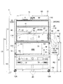
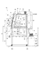
図1は、本発明の機器封じ込め装置の第1実施形態の全体構成を示す正面図である。図2は、図1に示す機器封じ込め装置1を示す側面図である。
<First Embodiment>
FIG. 1 is a front view showing the overall configuration of the first embodiment of the device containment apparatus of the present invention. FIG. 2 is a side view showing the
図1と図2に示す機器封じ込め装置1は、好ましくは作業空間Gを用いて作業や実験を行う際に、空気を低風量ドラフトで通過させる低風量ドラフトチャンバである。この機器封じ込め装置1は、その庫内の作業空間Gにおいて、作業者により対象の機器等の比較的大型の装置や機器類を用いて、求められる作業や実験を行うのに用いられる。
The
封じ込めようとする対象の機器としては、天秤や各種の器具等に比べて、比較的大型のサイズを有する、例えば薬剤の粉体をカプセルに充填する装置や、分析対象物を分析する分析装置である。 The target device to be contained is a device having a relatively large size compared to a balance, various instruments, etc., for example, a device for filling a capsule with a drug powder or an analysis device for analyzing an analysis target. is there.
この機器封じ込め装置1は、近年省エネルギーの観点から、従来の風量より少ない排気風量で稼働できるものが求められている。このような機器封じ込め装置1としては、一般的に「低風量ドラフトチャンバ」あるいは「低風量フュームフード」と呼称されている。この機器封じ込め装置1における風量は、通常のドラフトチャンバにおける風量と比較して、例えば50%から60%の風量で、ドラフトチャンバ庫内の有害ガス等を封じ込めておくことが可能である。
In recent years, the
機器封じ込め装置1としては、好ましくは例えば排気風量が常に一定(CAV:定風量制御)である定風量型のものが採用できる。しかし、機器封じ込め装置1は、これに限らず、更なる省エネルギー化の観点から、この定風量型のものに対して、VAV(可変風量制御)方式を組み合わせる可変風量型の物であっても良い。
As the
この機器封じ込め装置1は、例えば薬品の製造業務や、研究者や実験者等の作業者が例えば微生物等の試料の無菌操作作業や化学実験作業等、比較的大型の機器や必要に応じて作業や実験を行うために用いられる。
This
機器封じ込め装置1は、作業や実験における被処理物を内部の作業空間において処理する際に、作業者が被処理物や有害物質の影響を受けないように、内部の作業空間Gの雰囲気を外部から隔離する構造を有している。機器封じ込め装置1は、作業者を保護することを目的とした局所排気装置であり、危険物質や有害物質の封じ込め機能と、排気機能を有した囲われた作業空間Gを持っている。
The
特に、機器封じ込め装置1は、エネルギーコスト低減を目的として、少ないランニングコストで局所排気装置(ドラフトチャンバ)の運転ができることが望まれているが、この様な市場のニーズにより、排気風量を少なくして、一般的な機器封じ込め装置よりも低い前面風速で有害な雰囲気の漏洩防止が可能である。そのためには、低い前面風速においても作業空間Gから有害な雰囲気が外部に漏洩しない様にしながら、40〜60%排気風量を減らすことができる。
In particular, the
これにより、機器封じ込め装置1は、少ない風量ドラフトで運転して安全性を確保でき、風量ドラフト運転エネルギーの低減を図っており、空気の低い風量ドラフトにより空気の低排気量となることから、低ランニングコストが得られる。
As a result, the
次に、図1と図2を参照して、機器封じ込め装置1の好ましい構造例を、詳しく説明する。
Next, with reference to FIG. 1 and FIG. 2, the preferable structural example of the
図1と図2に示す機器封じ込め装置1は、例えばナノエンクロージャともいい、本体10と、本体10に付属させたファン・フィルターユニット80を有している。この本体10は、内部の作業空間Gが、本体10の外部に対して閉じたクローズドチャンバ構造を有する。
The
図1と図2に示すように、本体10は、正面側から見ると縦長の長方形になっている。図1と図2に示すように、本体10は、ケース部11と、架台部12を有する。
As shown in FIGS. 1 and 2, the
ケース部11は、上部2と、下部3を有している。ケース部11の下部3は、架台部12と一体化された構造になっており、ケース部11は、架台部12の上に固定されている。
The
本体1のケース部11の上部2と下部3の枠部材の材質としては、軽量化のために、例えば陽極酸化塗装複合被膜により被覆されたアルミニウム等の軽量な金属により作られているが、特に限定されない。架台部12の材質としては、ケース部11の重量を支えるために、例えばSUS等の丈夫な金属により作られているが、特に限定されない。
The material of the frame members of the
<ケース部11の上部2>
まず、図1と図2に示すケース部11の上部2について説明する。
<
First, the
図1と図2に示すように、ケース部11の上部2は、傾斜した前面部20と、上面部21と、背面部22と、左右の側面部23,24を有している。図2に示す背面部22は、ケース部11の背面を覆っており、例えばアルミニウム板である。
As shown in FIGS. 1 and 2, the
ケース部11は、例えば縦方向の枠部材11A,11B,11C,11D,11H,11I等と、横方向の枠部材11E,11G,11J、11K、11L等を連結することにより作られている。ケース部11の内部には、収容対象となる比較的大型の機器M等を収納するために、作業空間Gが形成されている。この作業空間Gは、縦長のほぼ直方体形状を有する空間である。
The
図1と図2に示すように、架台部12は、底部の四隅部に、キャスタ12Aを備える。各キャスタ12Aは、高さ調整が可能になるように、アジャストボルトを有する。各キャスタ12Aは、各アジャスタボルトを回転させることで、床面FW上において架台部12を水平に保持することができる。ケース部11の作業空間G内に配置する対象の機器Mは、精密な機器であるので、水平度を保つことも重要である。
As shown in FIGS. 1 and 2, the
<ケース部11の前面部20>
次に、図2を参照して、傾斜した前面部20の構造例について説明する。
<
Next, a structural example of the inclined
図2に示すように、ケース部11の前面部20の上部は、作業者が立ち姿勢で作業をし易いように、水平線HLに対して角度θだけ後側に傾いていて、図1と図2に示すように第1前面開口部分30を有している。この第1前面開口部分30は、作業者が例えば対象の機器Mを作業空間G内に搬入したり、搬出するのに用いる。
As shown in FIG. 2, the upper portion of the
図2に示すように、この第1前面開口部分30は、縦方向の最大開口幅OPを有している。図1と図2に示すように、第1前面開口部分30には、前面扉31が開閉可能に配置されている。この前面扉31は、例えば透明の強化ガラスである。
As shown in FIG. 2, the first
前面扉31は、例えばバランスウェイト方式で、図1に示す左右の案内レール32,33に沿って図2に示す斜め上方向Sに持ち上げてスライドすると、図2に示す開口幅Dだけ、第1前面開口部分30を開くことができる。
When the
また、この前面扉31は、斜め上方向Sに持ち上げてスライドした後に、図2の矢印Nで示すように、上下跳ね上げ式で格納部99に格納できる。これにより、図2に示す最大開口幅OPだけ、第1前面開口部分30を開くことができる。
Further, after the
このように、前面扉31は、斜め上方向Sに沿ってスライドして上げて、しかも矢印Nに沿って180度跳ね上げることにより、第1前面開口部分30を、最大開口幅OPだけ全開することができる。これにより、作業者は、比較的大型の対象の機器Mを作業空間G内に搬入したり、搬出することが容易に行える。
Thus, the
上述したように、前面部20では、作業者は、作業空間G内に天秤や器具等を出し入れする場合には、前面扉31を必要な量だけ上げて、第1前面開口部分30を開口幅Dだけ開けることができる。また、天秤や器具等よりも大型の対象の機器Mを出し入れする場合には、前面扉31を上げて、第1前面開口部分30を最大開口幅OPだけ開けることができる。
As described above, in the
逆に、図2に示すように、前面扉31は、矢印Nに沿って半回転だけ回して下げて、しかも矢印S1方向に沿って斜めにスライドして下げることにより、前面扉31は、第1前面開口部分30を全閉することができる。
On the contrary, as shown in FIG. 2, the
図1と図2に示すケース部11の左右の側面部23,24は、それぞれ側面窓23A,24Aを有している。これらの側面窓23A,24Aは、作業者が作業空間G内を観察できるように、好ましくは透明のプラスチック板、例えば塩化ビニールの板である。
The left and right side surfaces 23 and 24 of the
図1に示すように、左側の側面部23には、例えば1つのグローブポート40が設けられている。グローブポート40は、作業者の手を挿入して作業空間G内で作業を行うための挿肢口である。グローブポート40には、袖の長いゴム手袋41が取り付けられている。
As shown in FIG. 1, for example, one
このため、作業者は、手をグローブポート40のゴム手袋41に入れることにより、作業者の手は、側面窓23A側から図1に示すケース部11内の上部2の作業空間G内で、ゴム手袋41に覆われたままで入れて、上部2の作業空間G内での必要な作業を、安全に行うことができる。
For this reason, the operator puts his / her hand into the
なお、図1と図2に示すように、右側の側面部24には、ダストフランジ43が設けられている。このダストフランジ43には、図1に示す廃棄物回収バッグ44が着脱可能に取り付けられている。これにより、作業者は、手をグローブポート40のゴム手袋41に入れて、作業空間G内で生じた廃棄物を、作業空間Gの外部とは隔離された状態で、廃棄物回収バッグ44内に収容することで廃棄できる。
As shown in FIGS. 1 and 2, a
その他に、図2に示すように、上部2の作業空間Gには、作業空間G内の気流の整流するためのバッフルプレート45が、着台可能に配置されている。
In addition, as shown in FIG. 2, a
<ケース部11の下部3>
次に、図1と図2を参照して、ケース部11の下部3に構造について説明する。
<
Next, the structure of the
図1と図2に示すように、ケース部11の下部3は、上部2の下側にあり、架台部12の上に配置されている。下部3は、左右の側面パネル51,52と、背面パネル53を有している。左右の側面パネル51,52と、背面パネル53は、例えばアルミニウムパネルである。図2に示すように、右側の側面パネル52は、電気ケーブル等を外部に引き出すためのケーブル孔52Hを有する。
As shown in FIGS. 1 and 2, the
図1と図2に示すように、下部3の前面には、機器搬入用の第2前面開口部分60が設けられている。この第2前面開口部分60は、上述した第1前面開口部分30とともに同時に開放することで、第2前面開口部分60と第1前面開口部分30は、より大きな開口面積を有する機器搬入用の前面開口領域部88を形成することができる。
As shown in FIG. 1 and FIG. 2, a second front opening 60 for carrying in equipment is provided on the front surface of the
この機器搬入用の前面開口領域部88は、作業者が、図1と図2に例示する対象の比較的大型の機器Mを、作業空間G内に入れたり、必要に応じて機器Mを作業空間G内から取り出すために設けられている。
The
図2に示すように、閉鎖部材62が、機器搬入用の第2前面開口部分60を全閉するために、着脱可能に取り付けられている。この閉鎖部材62は、例えば4つの取り付け用ネジ63を用いて、ケース11の下部3に取り付けることで、対象の機器Mを作業空間G内に入れた後に、機器搬入用の前面開口部分60を閉鎖する。この閉鎖部材62は、例えば透明の強化ガラス板であるが、特に限定されない。
As shown in FIG. 2, a closing
このように、ケース部11の上部2には、上部2の作業空間Gに対応する位置に、第1前面開口部分30が設けられ、第1前面開口部分30は、前面扉31により開閉可能に覆って密閉することができる。また、ケース部11の下部3には、下部3の作業空間Gに対応する位置に、第2前面開口部分60が設けられ、第2前面開口部分60は、閉鎖部材62により開閉可能により覆って密閉することができる。
As described above, the
上述したように、ケース11の上部2と下部3では、この第1前面開口部分30と第2前面開口部分60は、対象の機器Mを作業空間G内に搬入するために、同時に開くことで、より大きな開口面積を有する機器搬入用の前面開口領域部88を構成している。これにより、作業者が、比較的大型の対象の機器Mを作業空間G内に搬入して、次に説明する載置台72に載せる際には、その作業を容易にしかも確実に行うことができる。
As described above, in the
なお、開口領域部を構成する第1前面開口部分30と第2前面開口部分60は、本実施形態では、前面としたが、側面や背面に設けるようにしたものであっても良い。
In addition, although the 1st front
<載置台72>
次に、ケース部11の作業空間G内に配置されている載置台72について説明する。
<Mounting table 72>
Next, the mounting table 72 disposed in the work space G of the
図1と図2に示すように、ケース部11の作業空間G内には、載置台72が配置されている。ケース部11の上部2と下部3の境界部分の床面FWからの高さは、第1高さ位置寸法R1で示している。載置台72は、ケース部11の下部3において、床面FWからの高さである第2高さ位置寸法R2において水平に配置されている。
As shown in FIGS. 1 and 2, a mounting table 72 is disposed in the work space G of the
載置台72は、ケース部11の下部3の位置であって、架台12の直ぐ上の位置に配置されている。載置台72の位置は、第1高さ位置寸法R1から見ると、下方向に掘り下げた位置である。載置台72の材質としては、例えばテラゾー等の人造大理石や、金属材料により作ることができるが、材質は特に限定されない。
The mounting table 72 is located at the position of the
図1を参照して、各部の寸法例を挙げると、第1高さ位置寸法R1は、床面FWから例えば1mであり、載置台72の第2高さ位置寸法R2は、例えば0.58mであり、第3高さ位置寸法R3は、0.42mである。また、第1高さ位置寸法R1から、作業空間G内に設置された対象の機器Mの上部分MTの上面までの第4高さ位置寸法R4は、例えば0.22mである。しかし、これらの寸法の値は、一例であり、特に限定されない。 With reference to FIG. 1, for example, the first height position dimension R1 is, for example, 1 m from the floor surface FW, and the second height position dimension R2 of the mounting table 72 is, for example, 0.58 m. And the third height position dimension R3 is 0.42 m. Further, the fourth height position dimension R4 from the first height position dimension R1 to the upper surface of the upper part MT of the target device M installed in the work space G is, for example, 0.22 m. However, the values of these dimensions are examples and are not particularly limited.
載置台72の第2高さ位置寸法R2は、対象の機器Mをこの載置台72に載せた状態で、対象の機器Mの上部分MTが、ケース部11の上部2の作業空間G内に、位置決めできるように設定されている。これにより、作業者が、立ち姿勢で、ゴム手袋41に入れた手を用いて、対象の機器Mの上部分MTにおいて、例えば後で説明する必要な薬剤の粉体をカプセル内に充填する作業が行える。
The second height position dimension R2 of the mounting table 72 is such that the upper part MT of the target device M is in the work space G in the
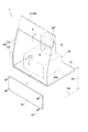
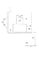
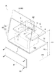
図3は、載置台72の形状例と、第1前面開口部分30と第2前面開口部分60と、前面扉31と、閉鎖部材62と、載置台72に載せた機器Mを示す斜視図であり、図4は、載置台72の形状例と、第1前面開口部分30と第2前面開口部分60と、載置台72に載せた機器Mを示す正面図である。
FIG. 3 is a perspective view showing a shape example of the mounting table 72, the first
図3と図4に示すように、載置台72は、ケース部11の上部2から掘り下げた位置、すなわちケース部11の下部3内に配置されており、載置台72は、比較的大型のサイズを有する対象の機器Mを載せることができる丈夫な板部材である。
As shown in FIGS. 3 and 4, the mounting table 72 is disposed in a position dug down from the
使用する対象の機器Mは、例えば直方体形状を有する本体部分MWと、この本体部分MWの上に設けられた上部分MTを有する。上部分MTのサイズは、本体部分MWのサイズよりも小さい。 The device M to be used includes, for example, a main body portion MW having a rectangular parallelepiped shape and an upper portion MT provided on the main body portion MW. The size of the upper part MT is smaller than the size of the main body part MW.
対象の機器Mとしては、例えば数マイクログラムの薬物の粉体を、カプセル内に分注して封入する装置である。対象の機器Mの上部分MTには、薬物の粉体を投入するための「じょうご」のような開口部が設けられている。しかも、対象の機器Mの上部分MTよりも少し下の位置には、操作部79が設けられている。薬物の粉体を分注して密封することで完成したカプセルは、操作部79の開口部から1つ1つ取り出すことができるようになっている。
The target device M is, for example, a device that dispenses and encloses a drug powder of several micrograms in a capsule. The upper part MT of the target device M is provided with an opening such as a “funnel” for charging drug powder. In addition, an
図1と図2に戻ると、上部2の上面部21には、各種の計器等を搭載したファン・フィルターユニットコントローラ75が配置されている。図1に示すように、架台部12には、電源コンセント76が配置されている。
Returning to FIG. 1 and FIG. 2, a fan /
また、図2に示すように、ファン・フィルターユニット80は、ホース81,82を介して、連結部83に接続されている。連結部83は、上面部21に配置されており、対象の機器Mが作業空間G内に排出する有害ガスは、連結部83とホース81,82を介して、ファン・フィルターユニット80に吸引される。ファン・フィルターユニット80は、例えば高性能なHEPAフィルタを内蔵しており、有害ガスから必要な物質を除去する。
As shown in FIG. 2, the fan /
<機器封じ込め装置1の使用例>
次に、上述した構造を有する機器封じ込め装置1の使用例を、図1から図4を参照して説明する。
<Usage example of
Next, a usage example of the
図2に示すように、作業者は、ケース部11の上部2において、前面扉31を、斜め上方向Sに沿ってスライドして上げて、しかも矢印Nに沿って180度跳ね上げる。これにより、第1前面開口部分30を、最大開口幅OPだけ全開する。また、図2に示すように、作業者は、ケース部11の下部3において、複数の取り付け用ネジ63を外して、閉鎖部材62を取り除いて第2前面開口部分60を開放する。
As shown in FIG. 2, the worker slides and raises the
これにより、図3と図4に示すように、第1前面開口部分30と第2前面開口部分60が同時に開放されることで、より大きな開口面積を有する機器搬入用の前面開口領域部88を、ケース部11の上部2と下部3において、上下方向に連続した開口領域部として形成する。
As a result, as shown in FIGS. 3 and 4, the first
そして、作業者は、図3と図4に示すように、この第1前面開口部分30と第2前面開口部分60を通じて、対象の機器Mを作業空間G内に入れる際に、対象の機器Mの本体部分MWを載置台72の上に載せる。そして、図3に示すようにC方向(機器封じ込め装置1の前側から後側に向けた方向)に載置台72上をスライドさせながら載置台72の所定位置に位置決めする。これにより、重量のある機器Mであっても、作業者は、安全にしかも確実に載せることができる。
Then, as shown in FIGS. 3 and 4, the operator places the target device M into the work space G through the first
作業者は、対象の機器Mの本体部分MWを載置台72の上に載せて位置決めした後に、作業者は、図2に示す前面扉31を、矢印Nに沿って180度だけ回転して下げて、斜め下方向S1に沿ってスライドして下げることにより、第1前面開口部分30を閉鎖する。また、作業者は、閉鎖部材62を機器搬入用の第2前面開口部分60に被せて、複数の取り付け用ネジ63を用いて固定する。これにより、第2前面開口部分60を閉鎖する。
After the operator places the main body portion MW of the target device M on the mounting table 72 and positions it, the operator rotates the
これにより、図1と図2に示すように、ケース部11の作業空間Gは、外気から閉ざされた密閉状態になる。図3と図4に示すように、有害物を排出する対象の機器Mは、その本体部分MWを、下部3の作業空間G内の載置台72の上に置いた状態で、対象の機器Mの突出した上部分MTは、上部2の作業空間G内に位置させる。
Thereby, as shown in FIG. 1 and FIG. 2, the work space G of the
作業者は、図1と図2に示すように、この比較的大型の対象の機器Mを機器封じ込め装置1のケース部11の作業空間G内に封じ込めた状態で、対象の機器Mを用いて、例えば次のような作業を行うことができる。
As shown in FIGS. 1 and 2, the worker uses the target device M in a state where the relatively large target device M is contained in the work space G of the
作業者は、手をグローブポート40のゴム手袋41に入れる。作業者は、立ち姿勢で、ケース部11の上部2内に位置された対象の機器Mの上部分MTにある薬物の粉体を入れる開口部に対して、薬物の粉体を投入する。この薬物の粉体は、対象の機器Mにおいてカプセル内に分注されてカプセルは封入される。作業者は、手をグローブポート40のゴム手袋41に入れることで、1つ1つの完成したカプセルを、操作部79の開口部から取り出すことができる。
The operator puts his hand into the
本発明の第1実施形態では、作業者が、対象の機器Mの本体部分MWの上部分MTの開口部に対して薬物の粉体を投入したり、完成したカプセルと取り出す作業を行う。載置台72は、ケース部11の下部3の作業空間G内において掘り下げた位置に配置されている。これにより、作業者が対称の機器Mの上部分MTにおいて必要な作業が容易に行えるように、ケース部11の上部2の作業空間Gには、対象の機器Mの上部分MTを位置させている。
In the first embodiment of the present invention, an operator performs an operation of putting a drug powder into an opening of an upper portion MT of a main body portion MW of a target device M or taking out a completed capsule. The mounting table 72 is arranged at a position dug down in the work space G of the
この上部分MTの床面FWからの高さは、例えば第1高さ位置寸法R1(床面FWから例えば1m)に、第4高さ位置寸法R4(第1高さ位置寸法R1から0.22m)を加えた位置に設定されている。第1高さ位置寸法R1と第4高さ位置寸法R4を加えた高さは、作業者が立ち姿勢で作業を行う際に、手で作業するのにふさわしい高さである。 The height of the upper portion MT from the floor surface FW is, for example, the first height position dimension R1 (for example, 1 m from the floor surface FW), and the fourth height position dimension R4 (from the first height position dimension R1 to 0.1 mm). 22m) is added. The height obtained by adding the first height position dimension R1 and the fourth height position dimension R4 is a height suitable for working by hand when the worker works in a standing posture.
このため、作業者は、機器Mの上部分MTを用いて、立ち姿勢で、薬物の粉体を投入でき、しかも立ち姿勢で、操作部79から完成したカプセルと取り出すことを、容易に行うことができる。従って、作業者が疲れることなく、機器Mを用いた作業が容易に行える。
For this reason, the operator can use the upper part MT of the device M to put the powder of the drug in a standing posture and easily take out the completed capsule from the
上述した機器封じ込め装置1を用いることにより、作業者が、比較的大型の対象の機器Mを、作業空間Gの雰囲気内に封じ込めた状態で、安全にかつ容易に必要な作業を行うことができる。
By using the
図1から図4に示す本発明の第1実施形態では、作業空間Gの下部の位置に、載置台72を備えている。作業者が、対象の機器Mを、作業空間Gの雰囲気内に封じ込めた状態で、機器Mを用いて、安全にかつ容易に必要な作業を行うことができる。 In the first embodiment of the present invention shown in FIGS. 1 to 4, a mounting table 72 is provided at a position below the work space G. An operator can perform necessary work safely and easily using the device M in a state where the target device M is sealed in the atmosphere of the work space G.
対象の機器Mは、機器封じ込め装置1のケース部11の作業空間G内に収容して作業空間G内に封じ込めることができる。対象の機器Mの上部分MTは、作業者が立ち姿勢で作業ができる高さに位置できるので、作業者の手は、対象の機器Mの上部分MTに対して、容易にアプローチすることができる。
The target device M can be accommodated in the work space G of the
<第2実施形態>
次に、本発明の第2実施形態の機器封じ込め装置1Aを、図5から図8を参照して説明する。本発明の第2実施形態の機器封じ込め装置1Aの構造は、上述した本発明の第1実施形態の機器封じ込め装置1の構造に比べて、ほぼ同じであるが、次に説明する構成内容が異なる。そこで、本発明の第2実施形態の機器封じ込め装置1Aとしては、異なる構成内容を以下に説明する。本発明の第1実施形態の機器封じ込め装置1の構造と同様の箇所には同じ符号を記して、その説明を用いることにする。
Second Embodiment
Next, a
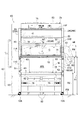
図5は、本発明の機器封じ込め装置の第1実施形態の全体構成を示す正面図である。図6は、図5に示す機器封じ込め装置1Aを示す側面図である。図7は、補助作業台71と載置台72の形状例と、第1前面開口部分30と第2前面開口部分60と、前面扉31と、閉鎖部材62と、補助作業台71と、載置台72に置かれた対象の機器Mを示す斜視図である。
FIG. 5 is a front view showing the overall configuration of the first embodiment of the device containment apparatus of the present invention. FIG. 6 is a side view showing the
また、図8は、補助作業台71と載置台72の形状例と、第1前面開口部分30と第2前面開口部分60と、前面扉31と、閉鎖部材62と、補助作業台71と、載置台72に置かれた対象の機器Mを示す正面図である。
Further, FIG. 8 shows examples of the shapes of the auxiliary work table 71 and the mounting table 72, the first
図5から図8に示す本発明の第2実施形態では、機器封じ込め装置1Aは、ケース部11の作業空間G内において、載置台72の他に、必要に応じて用いることができる着脱可能な補助作業台71を備えている。
In the second embodiment of the present invention shown in FIGS. 5 to 8, the
次に、ケース部11の作業空間G内に配置されている補助作業台71と載置台72について説明する。
Next, the auxiliary work table 71 and the mounting table 72 arranged in the work space G of the
図1と図2に示すように、補助作業台71は、上部2に配置されている。補助作業台71は、上部2において、第1高さ位置寸法R1において水平に配置されている。この補助作業台71は、好ましくはケース部11の上部2内において、着脱可能に取り付けられている。これにより、対象の機器Mによる作業において、補助作業台71が不要である時には、使用者は、補助作業台71を、ケース部11の上部2内から取り外すことができる。
As shown in FIGS. 1 and 2, the auxiliary work table 71 is disposed on the
一方、図1と図2に示す載置台72は、下部3において、第2高さ位置寸法R2において水平に配置されている。載置台72は、第1テーブルともいい、補助作業台71は、第2テーブルともいう。載置台72は、ケース部11の下の位置であって、架台12の直ぐ上の位置に配置されている。
On the other hand, the mounting table 72 shown in FIGS. 1 and 2 is horizontally disposed in the
補助作業台71と載置台72の材質としては、例えばテラゾー等の人造大理石や、金属材料により作ることができるが、材質は特に限定されない。 The material of the auxiliary work table 71 and the mounting table 72 can be made of, for example, artificial marble such as Terrazzo or a metal material, but the material is not particularly limited.
載置台72の第2高さ位置寸法R2は、対象の機器Mをこの載置台72に載せた状態で、対象の機器Mの上部分MTが、ケース部11の上部2の作業空間G内に、位置決めできるように設定されている。これにより、作業者が、立ち姿勢で、ゴム手袋41に入れた手を用いて、対象の機器Mの上部分MTにおいて必要な作業が行える。
The second height position dimension R2 of the mounting table 72 is such that the upper part MT of the target device M is in the work space G in the
図7と図8に示すように、載置台72は、補助作業台71からは掘り下げた位置、すなわちケース部11の下部3内に配置されており、載置台72は、比較的大型のサイズを有する対象の機器Mを載せることができる丈夫な板部材である。
As shown in FIGS. 7 and 8, the mounting table 72 is disposed in a position dug down from the auxiliary work table 71, that is, in the
これに対して、図7と図8に示すように、補助作業台71には、例えば長方形に形成された通し用の開口部分73を有している。通し用の開口部分73は、補助作業台71の前端部側から切り欠くことで形成されている。この通し用の開口部分73には、対象の機器Mの一部分である上部分MTを、図3のC方向に沿って通すことができる。
On the other hand, as shown in FIGS. 7 and 8, the auxiliary work table 71 has a through
これにより、対象の機器Mの本体部分MWを載置台72の上にスライドして載せて所定位置の位置決めする際に、機器MをC方向(機器封じ込め装置1Aの前側から後側に向けた方向)にずらすことで、上部分MTは、補助作業台71の通し用の開口部分73を通して、補助作業台71の上方へ向けて、作業空間G内に位置させることができる。つまり、機器MをC方向にずらして載置台72に載せる際に、上部分MTは、補助作業台71には当たらずに、作業者が、上部分MTにおいて作業がし易いように、補助作業台71の上側に突出させることができる。
Thus, when the main body MW of the target device M is slid onto the mounting table 72 and positioned at a predetermined position, the device M is moved in the C direction (the direction from the front side to the rear side of the
<機器封じ込め装置1Aの使用例>
次に、上述した構造を有する機器封じ込め装置1Aの使用例を、図5から図8を参照して説明する。
<Usage example of
Next, usage examples of the
図6に示すように、作業者は、ケース部11の上部分2においては、前面扉31を、斜め上方向Sに沿ってスライドして上げて、しかも矢印Nに沿って180度だけ跳ね上げる。これにより、第1前面開口部分30を、最大開口幅OPだけ全開する。また、作業者は、ケース部11の下部分3においては、複数の取り付け用ネジ63を外して、閉鎖部材62を取り除いて第2前面開口部分60を開放する。
As shown in FIG. 6, in the
これにより、第1前面開口部分30と第2前面開口部分60が同時に開放されることで、より大きな開口面積を有する連続した機器搬入用の前面開口領域部88を、ケース部11の上部2と下部3に渡って上下方向に形成する。
As a result, the first
そして、作業者は、この第1前面開口部分30と第2前面開口部分60を通じて対象の機器Mを作業空間G内に入れる際に、対象の機器Mの本体部分MWを載置台72の上に載せて、図3に示すようにC方向にスライドさせながら載置台72の所定位置に位置決めする。
Then, when the worker puts the target device M into the work space G through the first
この際には、図3に示すように、対象の機器Mの上部分MTは、補助作業台71の通し用の開口部分73を通じて、補助作業台71に当たらないようにして、補助作業台71の上方に突出させることができる。
At this time, as shown in FIG. 3, the upper part MT of the target device M does not contact the auxiliary work table 71 through the
このようにして、作業者は、対象の機器Mの本体部分MWを載置台72の上に載せて位置決めした後に、作業者は、図2に示す前面扉31を、矢印Nに沿って180度回転して下げて、斜め下方向S1に沿ってスライドして下げることにより、第1前面開口部分30を閉鎖する。また、閉鎖部材62を機器搬入用の第2前面開口部分60に被せて複数の取り付け用ネジ63を用いて固定する。これにより、第2前面開口部分60を閉鎖する。
In this way, after the worker places the main body portion MW of the target device M on the mounting table 72 and positions it, the worker moves the
これにより、図1と図2に示すように、ケース部11の作業空間Gは外気からは密閉状態になる。図3と図4に示すように、有害物を排出する対象の機器Mは、その本体部分MWを、下部3の作業空間G内の載置台72の上に置いた状態で、対象の機器Mの突出した上部分MTは、補助作業台71の通し用の開口部分73を通じて、上部2の作業空間G内に位置させることができる。
Thereby, as shown in FIGS. 1 and 2, the work space G of the
この第2実施形態では、作業者は、前面扉31を上げて第1前面開口部分30を開けることにより、図7と図8に示す補助作業台71には、必要に応じて、図7に例示するように必要な測定機器や器具等Pを、ケース部11の上部2内の作業空間G内に入れて、補助作業台71の上に載せることができる。作業者は、測定機器や器具等Pの出し入れを、立ち姿勢で容易に行うことができる。
In the second embodiment, the operator raises the
第2実施形態の機器封じ込め装置1Aを用いることにより、作業者が、対象の機器Mを、作業空間Gの雰囲気内に封じ込めた状態で、安全にかつ容易に必要な作業を行うことができる。
By using the
なお、本発明の実施形態の機器封じ込め装置1(1A)では、作業者は、閉鎖部材62を取り除くことで第2前面開口部分60を通じて、対象の機器Mの本体部分MWに容易にアプローチできる。これにより、対象の機器Mの本体部分MWの調整作業等が容易に行える。
In the device containment apparatus 1 (1A) according to the embodiment of the present invention, the operator can easily approach the main body portion MW of the target device M through the second
以上説明したように、本発明の実施形態の機器封じ込め装置1(1A)は、閉鎖された本体10の作業空間G内で作業を行う機器Mを外気に対して封じ込めるための機器封じ込め装置である。本体10は、作業空間Gを形成しており上部2と下部3を有しているケース部11と、ケース部11の下部3の作業空間G内に配置されて、機器Mを載せるための載置台72と、機器Mを作業空間G内に搬入するために開閉可能な機器搬入用の前面開口領域部88を備える。
As described above, the device containment device 1 (1A) according to the embodiment of the present invention is a device containment device for containing the device M that performs work in the work space G of the closed
これにより、機器Mは、機器搬入用の前面開口領域部88を開けた状態で、ケース部11の下部3にある載置台72に載せることができ、機器Mを載置台72に載せた後は、機器搬入用の前面開口領域部88を閉じることで、ケース部11は外気に対して閉鎖できる。このため、作業者が、対象の機器Mが大型であっても、機器Mを作業空間Gの雰囲気内に封じ込めた状態で、安全にかつ容易に作業を行うことができる。
As a result, the device M can be placed on the mounting table 72 in the
また、機器Mは、ケース部11の下部3にある載置台72に載せるので、比較的大型の機器であっても、ケース部11内に収めることができ、使用者は、機器11を立ち姿勢で操作することができる。
In addition, since the device M is placed on the mounting table 72 in the
ケース部11の上部2には、上部2の作業空間Gに対応する位置に、第1前面開口部分30が設けられ、第1前面開口部分30は、前面扉31により開閉可能により覆われ、ケース部11の下部3には、下部3の作業空間Gに対応する位置に、第2前面開口部分60が設けられ、第2前面開口部分60は、閉鎖部材62により開閉可能により覆われ、機器搬入用の前面開口領域部88は、第1前面開口部分30と第2前面開口部分60から形成される。
The
これにより、第1前面開口部分30と第2前面開口部分60から形成される機器搬入用の前面開口領域部88を開けることにより、大型の機器Mであっても、載置台72に載せた状態で、ケース部11内に収容することができる。重量のある大型の機器Mであっても、載置台72上をスライドさせながら載置台72の所定の位置に設定することができ、作業者は、対象とする機器Mをケース部11内に収容する作業を容易に行うことができる。
Thereby, even if it is the large sized apparatus M, the state mounted on the mounting
ケース部11の上部2の作業空間G内に配置される補助作業台71を備え、補助作業台71は、機器Mの上部2を通して補助作業台71の上に突出させるための通し用の開口部分73を有する。
The auxiliary work table 71 is provided in the work space G in the
これにより、必要に応じて、ケース部11の上部2の作業空間G内には、補助作業台71を配置することができるので、作業に必要な器具Pなどを載せることができる。この場合に、補助作業台71は、通し用の開口部分73を有しており、機器Mが大型で上方に突き出た上部分MTを有していても、この上部分MTは通し用の開口部分73に通すことで、機器Mが補助作業台71に干渉せず、作業者は、例えば立ち姿勢で、上部2の作業空間Gでの作業を行うことができる。
As a result, the auxiliary work table 71 can be disposed in the work space G of the
機器封じ込め装置1(1A)では、作業空間内は、低風量で排気される。これにより、低風量で、作業空間内に有害ガス等を封じ込めておくことができるので、省エネルギー化が図れる。 In the device containment device 1 (1A), the work space is exhausted with a low air volume. As a result, it is possible to conserve harmful gases and the like in the work space with a low air volume, and thus energy saving can be achieved.
以上、実施形態を挙げて本発明を説明したが、各実施形態は一例であり、特許請求の範囲に記載される発明の範囲は、発明の要旨を逸脱しない範囲内で種々変更できるものである。本発明の各実施形態は、任意に組み合わせることができる。 The present invention has been described with reference to the embodiments. However, each embodiment is an example, and the scope of the invention described in the claims can be variously modified without departing from the scope of the invention. . Each embodiment of the present invention can be arbitrarily combined.
対象の機器Mとしては、薬物の粉体を、カプセルに充填して封入する装置に限らず、他の種類の機器、例えば分析機器や制御機器等であっても良い。この対象の機器Mが、薬物の粉体をカプセルに分注する装置や、分析機器や制御機器等は、その上部に作業あるいは操作をする部分が配置されていることがある。このような対象の機器の場合には、本発明の実施形態の機器封じ込め装置の使用が有効である。 The target device M is not limited to a device that fills and encapsulates a drug powder in a capsule, but may be another type of device, such as an analytical device or a control device. The target device M is a device for dispensing drug powder into capsules, an analytical device, a control device, or the like, and a portion for performing work or operation may be disposed on the upper portion thereof. In the case of such a target device, it is effective to use the device containment device of the embodiment of the present invention.
1 機器封じ込め装置
1A 機器封じ込め装置
2 ケース部の上部
3 ケース部の下部
10 本体
11 ケース部
12 架台部
20 前面部
30 第1前面開口部分(機器搬入用の前面開口領域部を形成する部分)
31 前面扉
60 第2前面開口部分(機器搬入用の前面開口領域部を形成する部分)
62 閉鎖部材
71 補助作業台
72 載置台
73 補助作業台の通し用の開口部分
88 機器搬入用の前面開口領域部
G 作業空間
M 対象の機器
MT 機器の上部分
MW 機器の本体部分
P 小型の測定機器や器具等
DESCRIPTION OF
31
62
Claims (4)
前記本体は、
前記作業空間を形成しており上部と下部を有するケース部と、
前記ケース部の前記下部の前記作業空間内に配置されて、前記機器を載せるための載置台と、
前記機器を前記作業空間内に搬入するために開閉可能な機器搬入用の開口領域部と、を備えることを特徴とする機器封じ込め装置。 An equipment containment device for containing equipment that operates in a closed work space of the main body against outside air,
The body is
A case portion forming the working space and having an upper portion and a lower portion;
A mounting table disposed in the work space at the lower part of the case part for mounting the device;
An apparatus containment device, comprising: an opening area for loading an apparatus that can be opened and closed to carry the apparatus into the work space.
前記ケース部の前記下部には、前記下部の作業空間に対応する前面位置に、第2前面開口部分が設けられ、前記第2前面開口部分は、閉鎖部材により開閉可能により覆われ、
前記機器搬入用の前面開口領域部は、前記第1前面開口部分と前記第2前面開口部分から形成されることを特徴とする請求項1に記載の機器封じ込め装置。 The upper portion of the case portion is provided with a first front opening portion at a position corresponding to the upper working space, and the first front opening portion is covered by a front door so as to be opened and closed.
The lower portion of the case portion is provided with a second front opening portion at a front surface position corresponding to the lower working space, and the second front opening portion is covered with a closing member so as to be opened and closed.
2. The device containment apparatus according to claim 1, wherein the front opening area for carrying in the device is formed of the first front opening portion and the second front opening portion.
前記補助作業台は、前記機器の上部分を通して前記補助作業台の上方に突出させるための通し用の開口部分を有することを特徴とする請求項1または2に記載の機器封じ込め装置。 An auxiliary workbench arranged in the upper working space of the case part;
The device containment apparatus according to claim 1, wherein the auxiliary workbench has a through-opening portion for projecting upward of the auxiliary workbench through an upper part of the device.
Priority Applications (1)
| Application Number | Priority Date | Filing Date | Title |
|---|---|---|---|
| JP2015119014A JP6688017B2 (en) | 2015-06-12 | 2015-06-12 | Equipment containment device |
Applications Claiming Priority (1)
| Application Number | Priority Date | Filing Date | Title |
|---|---|---|---|
| JP2015119014A JP6688017B2 (en) | 2015-06-12 | 2015-06-12 | Equipment containment device |
Publications (2)
| Publication Number | Publication Date |
|---|---|
| JP2017000978A true JP2017000978A (en) | 2017-01-05 |
| JP6688017B2 JP6688017B2 (en) | 2020-04-28 |
Family
ID=57753294
Family Applications (1)
| Application Number | Title | Priority Date | Filing Date |
|---|---|---|---|
| JP2015119014A Active JP6688017B2 (en) | 2015-06-12 | 2015-06-12 | Equipment containment device |
Country Status (1)
| Country | Link |
|---|---|
| JP (1) | JP6688017B2 (en) |
Cited By (2)
| Publication number | Priority date | Publication date | Assignee | Title |
|---|---|---|---|---|
| WO2019207877A1 (en) * | 2018-04-24 | 2019-10-31 | 株式会社日立産機システム | Safety cabinet |
| CN110449193A (en) * | 2019-09-10 | 2019-11-15 | 贵州哈雷空天环境工程有限公司 | A kind of anaerobism chamber for test |
Citations (4)
| Publication number | Priority date | Publication date | Assignee | Title |
|---|---|---|---|---|
| JPH0731889A (en) * | 1993-07-23 | 1995-02-03 | Itoki Crebio Corp | Draft chamber |
| JP2014034072A (en) * | 2012-08-08 | 2014-02-24 | Yaskawa Electric Corp | Robot system |
| JP2015009187A (en) * | 2013-06-28 | 2015-01-19 | ヤマト科学株式会社 | Low air-capacity draft chamber |
| JP5724000B1 (en) * | 2014-01-30 | 2015-05-27 | 株式会社日本医化器械製作所 | Globe panel |
-
2015
- 2015-06-12 JP JP2015119014A patent/JP6688017B2/en active Active
Patent Citations (4)
| Publication number | Priority date | Publication date | Assignee | Title |
|---|---|---|---|---|
| JPH0731889A (en) * | 1993-07-23 | 1995-02-03 | Itoki Crebio Corp | Draft chamber |
| JP2014034072A (en) * | 2012-08-08 | 2014-02-24 | Yaskawa Electric Corp | Robot system |
| JP2015009187A (en) * | 2013-06-28 | 2015-01-19 | ヤマト科学株式会社 | Low air-capacity draft chamber |
| JP5724000B1 (en) * | 2014-01-30 | 2015-05-27 | 株式会社日本医化器械製作所 | Globe panel |
Cited By (2)
| Publication number | Priority date | Publication date | Assignee | Title |
|---|---|---|---|---|
| WO2019207877A1 (en) * | 2018-04-24 | 2019-10-31 | 株式会社日立産機システム | Safety cabinet |
| CN110449193A (en) * | 2019-09-10 | 2019-11-15 | 贵州哈雷空天环境工程有限公司 | A kind of anaerobism chamber for test |
Also Published As
| Publication number | Publication date |
|---|---|
| JP6688017B2 (en) | 2020-04-28 |
Similar Documents
| Publication | Publication Date | Title |
|---|---|---|
| JP6688017B2 (en) | Equipment containment device | |
| JP6542609B2 (en) | Equipment containment device | |
| JPH0957438A (en) | Dust collecting equipment of thermal cutting machine | |
| US6431975B1 (en) | Fume hood for large containers | |
| CA2248500C (en) | Hood door airfoil | |
| JP5609933B2 (en) | Robot system | |
| JP6546463B2 (en) | Equipment containment device | |
| CN204817425U (en) | Environment -friendly fume hood | |
| CN207615878U (en) | Single head Multi-station circulating planar laser marking machine | |
| JP2013128462A (en) | Dispensing system, isolator | |
| US6843541B1 (en) | Glove box for water pit applications | |
| CN211137230U (en) | Glove box triaxial operation panel | |
| CN112473753B (en) | Biological safety cabinet | |
| JP2012063056A (en) | Pass box, and isolator device including same | |
| JP3185604U (en) | Attachment panel of cabinet for biohazard countermeasures | |
| JPH07290267A (en) | Welding and fusing machine | |
| CN205785455U (en) | A kind of packaged type meausring apparatus | |
| CN220863022U (en) | Laser marking machine | |
| JP6588349B2 (en) | Containment system | |
| CN219275894U (en) | Multi-angle operation laboratory glove box | |
| EP3817858B1 (en) | Protecting safety screen for a fume hood and fume hood incorporating the screen and method of use | |
| JPH0524240Y2 (en) | ||
| CN211359992U (en) | Chemical experiment fume hood | |
| CN219977091U (en) | Tubular furnace for laboratory | |
| NL1041230B1 (en) | Portable decontamination device for performing contamination-causing work on an object placed on a wall. |
Legal Events
| Date | Code | Title | Description |
|---|---|---|---|
| A521 | Request for written amendment filed |
Free format text: JAPANESE INTERMEDIATE CODE: A821 Effective date: 20150715 |
|
| A621 | Written request for application examination |
Free format text: JAPANESE INTERMEDIATE CODE: A621 Effective date: 20180419 |
|
| A977 | Report on retrieval |
Free format text: JAPANESE INTERMEDIATE CODE: A971007 Effective date: 20190109 |
|
| A131 | Notification of reasons for refusal |
Free format text: JAPANESE INTERMEDIATE CODE: A131 Effective date: 20190115 |
|
| A521 | Request for written amendment filed |
Free format text: JAPANESE INTERMEDIATE CODE: A523 Effective date: 20190314 |
|
| A131 | Notification of reasons for refusal |
Free format text: JAPANESE INTERMEDIATE CODE: A131 Effective date: 20190723 |
|
| A601 | Written request for extension of time |
Free format text: JAPANESE INTERMEDIATE CODE: A601 Effective date: 20190913 |
|
| A521 | Request for written amendment filed |
Free format text: JAPANESE INTERMEDIATE CODE: A523 Effective date: 20191121 |
|
| TRDD | Decision of grant or rejection written | ||
| A01 | Written decision to grant a patent or to grant a registration (utility model) |
Free format text: JAPANESE INTERMEDIATE CODE: A01 Effective date: 20200324 |
|
| A61 | First payment of annual fees (during grant procedure) |
Free format text: JAPANESE INTERMEDIATE CODE: A61 Effective date: 20200403 |
|
| R150 | Certificate of patent or registration of utility model |
Ref document number: 6688017 Country of ref document: JP Free format text: JAPANESE INTERMEDIATE CODE: R150 |
|
| R250 | Receipt of annual fees |
Free format text: JAPANESE INTERMEDIATE CODE: R250 |
|
| R250 | Receipt of annual fees |
Free format text: JAPANESE INTERMEDIATE CODE: R250 |