JP2016540887A - Three-dimensional printed hot isostatic pressing container and method for producing the same - Google Patents
Three-dimensional printed hot isostatic pressing container and method for producing the same Download PDFInfo
- Publication number
- JP2016540887A JP2016540887A JP2016523314A JP2016523314A JP2016540887A JP 2016540887 A JP2016540887 A JP 2016540887A JP 2016523314 A JP2016523314 A JP 2016523314A JP 2016523314 A JP2016523314 A JP 2016523314A JP 2016540887 A JP2016540887 A JP 2016540887A
- Authority
- JP
- Japan
- Prior art keywords
- container
- cavity
- coating
- powder
- isostatic pressing
- Prior art date
- Legal status (The legal status is an assumption and is not a legal conclusion. Google has not performed a legal analysis and makes no representation as to the accuracy of the status listed.)
- Pending
Links
Images
Classifications
-
- B—PERFORMING OPERATIONS; TRANSPORTING
- B22—CASTING; POWDER METALLURGY
- B22F—WORKING METALLIC POWDER; MANUFACTURE OF ARTICLES FROM METALLIC POWDER; MAKING METALLIC POWDER; APPARATUS OR DEVICES SPECIALLY ADAPTED FOR METALLIC POWDER
- B22F3/00—Manufacture of workpieces or articles from metallic powder characterised by the manner of compacting or sintering; Apparatus specially adapted therefor ; Presses and furnaces
- B22F3/12—Both compacting and sintering
- B22F3/1208—Containers or coating used therefor
- B22F3/1258—Container manufacturing
- B22F3/1266—Container manufacturing by coating or sealing the surface of the preformed article, e.g. by melting
-
- B—PERFORMING OPERATIONS; TRANSPORTING
- B22—CASTING; POWDER METALLURGY
- B22F—WORKING METALLIC POWDER; MANUFACTURE OF ARTICLES FROM METALLIC POWDER; MAKING METALLIC POWDER; APPARATUS OR DEVICES SPECIALLY ADAPTED FOR METALLIC POWDER
- B22F10/00—Additive manufacturing of workpieces or articles from metallic powder
- B22F10/60—Treatment of workpieces or articles after build-up
- B22F10/62—Treatment of workpieces or articles after build-up by chemical means
-
- B—PERFORMING OPERATIONS; TRANSPORTING
- B22—CASTING; POWDER METALLURGY
- B22F—WORKING METALLIC POWDER; MANUFACTURE OF ARTICLES FROM METALLIC POWDER; MAKING METALLIC POWDER; APPARATUS OR DEVICES SPECIALLY ADAPTED FOR METALLIC POWDER
- B22F10/00—Additive manufacturing of workpieces or articles from metallic powder
- B22F10/60—Treatment of workpieces or articles after build-up
- B22F10/64—Treatment of workpieces or articles after build-up by thermal means
-
- B—PERFORMING OPERATIONS; TRANSPORTING
- B22—CASTING; POWDER METALLURGY
- B22F—WORKING METALLIC POWDER; MANUFACTURE OF ARTICLES FROM METALLIC POWDER; MAKING METALLIC POWDER; APPARATUS OR DEVICES SPECIALLY ADAPTED FOR METALLIC POWDER
- B22F3/00—Manufacture of workpieces or articles from metallic powder characterised by the manner of compacting or sintering; Apparatus specially adapted therefor ; Presses and furnaces
- B22F3/12—Both compacting and sintering
- B22F3/1208—Containers or coating used therefor
- B22F3/1258—Container manufacturing
-
- B—PERFORMING OPERATIONS; TRANSPORTING
- B22—CASTING; POWDER METALLURGY
- B22F—WORKING METALLIC POWDER; MANUFACTURE OF ARTICLES FROM METALLIC POWDER; MAKING METALLIC POWDER; APPARATUS OR DEVICES SPECIALLY ADAPTED FOR METALLIC POWDER
- B22F3/00—Manufacture of workpieces or articles from metallic powder characterised by the manner of compacting or sintering; Apparatus specially adapted therefor ; Presses and furnaces
- B22F3/12—Both compacting and sintering
- B22F3/14—Both compacting and sintering simultaneously
- B22F3/15—Hot isostatic pressing
-
- B—PERFORMING OPERATIONS; TRANSPORTING
- B22—CASTING; POWDER METALLURGY
- B22F—WORKING METALLIC POWDER; MANUFACTURE OF ARTICLES FROM METALLIC POWDER; MAKING METALLIC POWDER; APPARATUS OR DEVICES SPECIALLY ADAPTED FOR METALLIC POWDER
- B22F5/00—Manufacture of workpieces or articles from metallic powder characterised by the special shape of the product
- B22F5/10—Manufacture of workpieces or articles from metallic powder characterised by the special shape of the product of articles with cavities or holes, not otherwise provided for in the preceding subgroups
-
- C—CHEMISTRY; METALLURGY
- C23—COATING METALLIC MATERIAL; COATING MATERIAL WITH METALLIC MATERIAL; CHEMICAL SURFACE TREATMENT; DIFFUSION TREATMENT OF METALLIC MATERIAL; COATING BY VACUUM EVAPORATION, BY SPUTTERING, BY ION IMPLANTATION OR BY CHEMICAL VAPOUR DEPOSITION, IN GENERAL; INHIBITING CORROSION OF METALLIC MATERIAL OR INCRUSTATION IN GENERAL
- C23C—COATING METALLIC MATERIAL; COATING MATERIAL WITH METALLIC MATERIAL; SURFACE TREATMENT OF METALLIC MATERIAL BY DIFFUSION INTO THE SURFACE, BY CHEMICAL CONVERSION OR SUBSTITUTION; COATING BY VACUUM EVAPORATION, BY SPUTTERING, BY ION IMPLANTATION OR BY CHEMICAL VAPOUR DEPOSITION, IN GENERAL
- C23C18/00—Chemical coating by decomposition of either liquid compounds or solutions of the coating forming compounds, without leaving reaction products of surface material in the coating; Contact plating
- C23C18/16—Chemical coating by decomposition of either liquid compounds or solutions of the coating forming compounds, without leaving reaction products of surface material in the coating; Contact plating by reduction or substitution, e.g. electroless plating
- C23C18/1601—Process or apparatus
- C23C18/1633—Process of electroless plating
- C23C18/1635—Composition of the substrate
- C23C18/1644—Composition of the substrate porous substrates
-
- C—CHEMISTRY; METALLURGY
- C25—ELECTROLYTIC OR ELECTROPHORETIC PROCESSES; APPARATUS THEREFOR
- C25D—PROCESSES FOR THE ELECTROLYTIC OR ELECTROPHORETIC PRODUCTION OF COATINGS; ELECTROFORMING; APPARATUS THEREFOR
- C25D7/00—Electroplating characterised by the article coated
- C25D7/04—Tubes; Rings; Hollow bodies
-
- B—PERFORMING OPERATIONS; TRANSPORTING
- B22—CASTING; POWDER METALLURGY
- B22F—WORKING METALLIC POWDER; MANUFACTURE OF ARTICLES FROM METALLIC POWDER; MAKING METALLIC POWDER; APPARATUS OR DEVICES SPECIALLY ADAPTED FOR METALLIC POWDER
- B22F10/00—Additive manufacturing of workpieces or articles from metallic powder
- B22F10/10—Formation of a green body
- B22F10/14—Formation of a green body by jetting of binder onto a bed of metal powder
-
- B—PERFORMING OPERATIONS; TRANSPORTING
- B22—CASTING; POWDER METALLURGY
- B22F—WORKING METALLIC POWDER; MANUFACTURE OF ARTICLES FROM METALLIC POWDER; MAKING METALLIC POWDER; APPARATUS OR DEVICES SPECIALLY ADAPTED FOR METALLIC POWDER
- B22F3/00—Manufacture of workpieces or articles from metallic powder characterised by the manner of compacting or sintering; Apparatus specially adapted therefor ; Presses and furnaces
- B22F3/12—Both compacting and sintering
- B22F3/14—Both compacting and sintering simultaneously
- B22F3/15—Hot isostatic pressing
- B22F2003/153—Hot isostatic pressing apparatus specific to HIP
-
- B—PERFORMING OPERATIONS; TRANSPORTING
- B22—CASTING; POWDER METALLURGY
- B22F—WORKING METALLIC POWDER; MANUFACTURE OF ARTICLES FROM METALLIC POWDER; MAKING METALLIC POWDER; APPARATUS OR DEVICES SPECIALLY ADAPTED FOR METALLIC POWDER
- B22F3/00—Manufacture of workpieces or articles from metallic powder characterised by the manner of compacting or sintering; Apparatus specially adapted therefor ; Presses and furnaces
- B22F3/24—After-treatment of workpieces or articles
- B22F2003/241—Chemical after-treatment on the surface
- B22F2003/242—Coating
-
- B—PERFORMING OPERATIONS; TRANSPORTING
- B22—CASTING; POWDER METALLURGY
- B22F—WORKING METALLIC POWDER; MANUFACTURE OF ARTICLES FROM METALLIC POWDER; MAKING METALLIC POWDER; APPARATUS OR DEVICES SPECIALLY ADAPTED FOR METALLIC POWDER
- B22F2301/00—Metallic composition of the powder or its coating
- B22F2301/15—Nickel or cobalt
-
- B—PERFORMING OPERATIONS; TRANSPORTING
- B22—CASTING; POWDER METALLURGY
- B22F—WORKING METALLIC POWDER; MANUFACTURE OF ARTICLES FROM METALLIC POWDER; MAKING METALLIC POWDER; APPARATUS OR DEVICES SPECIALLY ADAPTED FOR METALLIC POWDER
- B22F2301/00—Metallic composition of the powder or its coating
- B22F2301/35—Iron
-
- B—PERFORMING OPERATIONS; TRANSPORTING
- B22—CASTING; POWDER METALLURGY
- B22F—WORKING METALLIC POWDER; MANUFACTURE OF ARTICLES FROM METALLIC POWDER; MAKING METALLIC POWDER; APPARATUS OR DEVICES SPECIALLY ADAPTED FOR METALLIC POWDER
- B22F2302/00—Metal Compound, non-Metallic compound or non-metal composition of the powder or its coating
- B22F2302/20—Nitride
-
- B—PERFORMING OPERATIONS; TRANSPORTING
- B22—CASTING; POWDER METALLURGY
- B22F—WORKING METALLIC POWDER; MANUFACTURE OF ARTICLES FROM METALLIC POWDER; MAKING METALLIC POWDER; APPARATUS OR DEVICES SPECIALLY ADAPTED FOR METALLIC POWDER
- B22F2302/00—Metal Compound, non-Metallic compound or non-metal composition of the powder or its coating
- B22F2302/25—Oxide
- B22F2302/253—Aluminum oxide (Al2O3)
-
- B—PERFORMING OPERATIONS; TRANSPORTING
- B33—ADDITIVE MANUFACTURING TECHNOLOGY
- B33Y—ADDITIVE MANUFACTURING, i.e. MANUFACTURING OF THREE-DIMENSIONAL [3D] OBJECTS BY ADDITIVE DEPOSITION, ADDITIVE AGGLOMERATION OR ADDITIVE LAYERING, e.g. BY 3D PRINTING, STEREOLITHOGRAPHY OR SELECTIVE LASER SINTERING
- B33Y10/00—Processes of additive manufacturing
-
- B—PERFORMING OPERATIONS; TRANSPORTING
- B33—ADDITIVE MANUFACTURING TECHNOLOGY
- B33Y—ADDITIVE MANUFACTURING, i.e. MANUFACTURING OF THREE-DIMENSIONAL [3D] OBJECTS BY ADDITIVE DEPOSITION, ADDITIVE AGGLOMERATION OR ADDITIVE LAYERING, e.g. BY 3D PRINTING, STEREOLITHOGRAPHY OR SELECTIVE LASER SINTERING
- B33Y80/00—Products made by additive manufacturing
-
- C—CHEMISTRY; METALLURGY
- C23—COATING METALLIC MATERIAL; COATING MATERIAL WITH METALLIC MATERIAL; CHEMICAL SURFACE TREATMENT; DIFFUSION TREATMENT OF METALLIC MATERIAL; COATING BY VACUUM EVAPORATION, BY SPUTTERING, BY ION IMPLANTATION OR BY CHEMICAL VAPOUR DEPOSITION, IN GENERAL; INHIBITING CORROSION OF METALLIC MATERIAL OR INCRUSTATION IN GENERAL
- C23C—COATING METALLIC MATERIAL; COATING MATERIAL WITH METALLIC MATERIAL; SURFACE TREATMENT OF METALLIC MATERIAL BY DIFFUSION INTO THE SURFACE, BY CHEMICAL CONVERSION OR SUBSTITUTION; COATING BY VACUUM EVAPORATION, BY SPUTTERING, BY ION IMPLANTATION OR BY CHEMICAL VAPOUR DEPOSITION, IN GENERAL
- C23C18/00—Chemical coating by decomposition of either liquid compounds or solutions of the coating forming compounds, without leaving reaction products of surface material in the coating; Contact plating
- C23C18/16—Chemical coating by decomposition of either liquid compounds or solutions of the coating forming compounds, without leaving reaction products of surface material in the coating; Contact plating by reduction or substitution, e.g. electroless plating
- C23C18/31—Coating with metals
- C23C18/32—Coating with nickel, cobalt or mixtures thereof with phosphorus or boron
-
- C—CHEMISTRY; METALLURGY
- C23—COATING METALLIC MATERIAL; COATING MATERIAL WITH METALLIC MATERIAL; CHEMICAL SURFACE TREATMENT; DIFFUSION TREATMENT OF METALLIC MATERIAL; COATING BY VACUUM EVAPORATION, BY SPUTTERING, BY ION IMPLANTATION OR BY CHEMICAL VAPOUR DEPOSITION, IN GENERAL; INHIBITING CORROSION OF METALLIC MATERIAL OR INCRUSTATION IN GENERAL
- C23C—COATING METALLIC MATERIAL; COATING MATERIAL WITH METALLIC MATERIAL; SURFACE TREATMENT OF METALLIC MATERIAL BY DIFFUSION INTO THE SURFACE, BY CHEMICAL CONVERSION OR SUBSTITUTION; COATING BY VACUUM EVAPORATION, BY SPUTTERING, BY ION IMPLANTATION OR BY CHEMICAL VAPOUR DEPOSITION, IN GENERAL
- C23C4/00—Coating by spraying the coating material in the molten state, e.g. by flame, plasma or electric discharge
- C23C4/04—Coating by spraying the coating material in the molten state, e.g. by flame, plasma or electric discharge characterised by the coating material
- C23C4/10—Oxides, borides, carbides, nitrides or silicides; Mixtures thereof
- C23C4/11—Oxides
-
- Y—GENERAL TAGGING OF NEW TECHNOLOGICAL DEVELOPMENTS; GENERAL TAGGING OF CROSS-SECTIONAL TECHNOLOGIES SPANNING OVER SEVERAL SECTIONS OF THE IPC; TECHNICAL SUBJECTS COVERED BY FORMER USPC CROSS-REFERENCE ART COLLECTIONS [XRACs] AND DIGESTS
- Y02—TECHNOLOGIES OR APPLICATIONS FOR MITIGATION OR ADAPTATION AGAINST CLIMATE CHANGE
- Y02P—CLIMATE CHANGE MITIGATION TECHNOLOGIES IN THE PRODUCTION OR PROCESSING OF GOODS
- Y02P10/00—Technologies related to metal processing
- Y02P10/25—Process efficiency
Landscapes
- Chemical & Material Sciences (AREA)
- Engineering & Computer Science (AREA)
- Manufacturing & Machinery (AREA)
- Mechanical Engineering (AREA)
- Materials Engineering (AREA)
- Chemical Kinetics & Catalysis (AREA)
- General Chemical & Material Sciences (AREA)
- Metallurgy (AREA)
- Organic Chemistry (AREA)
- Electrochemistry (AREA)
- Physics & Mathematics (AREA)
- Thermal Sciences (AREA)
- Powder Metallurgy (AREA)
- Electroplating Methods And Accessories (AREA)
Abstract
粉末材料を熱間静水圧加圧成形することにより物品を形成するための熱間静水圧加圧成形用容器を製造する方法であって、造形粉末を以て当該容器を3次元印刷することから成り、当該容器は粉末材料を受容するための空洞と外面のある外側部を有し、当該空洞は表面を有し、当該空洞内に粉末材料がある状態で当該容器を熱間静水圧加圧成形すると当該物品が作り出されるような形状と大きさをしていることを特徴とする方法を開示する。当該容器を用いて熱間静水圧加圧成形品を製造する方法も開示する。
【選択図】図2A method for producing a hot isostatic pressing container for forming an article by hot isostatic pressing a powder material, comprising three-dimensional printing of the container with a modeling powder, The container has a cavity for receiving the powder material and an outer part having an outer surface, the cavity has a surface, and the container is subjected to hot isostatic pressing with the powder material in the cavity. Disclosed is a method characterized in that it is shaped and sized such that the article is created. A method for producing a hot isostatic pressing product using the container is also disclosed.
[Selection] Figure 2
Description
本発明は、熱間静水圧加圧成形に用いるための粉末容器を作成する方法、当該容器それ自体、及び熱間静水圧加圧成形されるパーツを製造するための当該容器の使用に関する。 The present invention relates to a method of making a powder container for use in hot isostatic pressing, the container itself, and the use of the container for producing parts to be hot isostatically pressed.
熱間静水圧加圧成形(HIP)とは、圧力が物体に塑性変形を引き起こすに十分な温度において物体に静水圧を加えることを意味する。HIPは、鋳造、粉末冶金、及びセラミックプロセスによって製造されるパーツ内に残っている多孔質をふさぐ、又は大きさを縮小することにより、当該パーツの密度を高めるために一般に用いられる。 Hot isostatic pressing (HIP) means applying hydrostatic pressure to an object at a temperature sufficient for the pressure to cause plastic deformation in the object. HIP is commonly used to increase the density of a part by plugging or reducing the size of the remaining porosity in the part produced by casting, powder metallurgy, and ceramic processes.
HIPは、金属粉末を固めて直接密度の高い物体にするための手段としても用いられる。金属粉末は、HIP温度において可鍛性のある容器の中に入れられる。当該容器は、ガスを排気するために真空ポンプに取り付けられる。多くの場合、容器は、粉末粒子及び容器の表面から吸着ガスを除去する手段として真空ポンプが取り付けられた状態で、加熱される。その後容器は、例えば高温圧着により密閉され、続いて粉末の種類、容器の大きさ、及びHIPプロセスの目的に基づいて選択される時間、温度、圧力の組み合わせで熱間静水圧加圧成形が施される。HIP終了後、容器は、機械加工及び/又は化学溶解により当該パーツから取り外される。 HIP is also used as a means for consolidating metal powder into a directly dense object. The metal powder is placed in a malleable container at the HIP temperature. The container is attached to a vacuum pump to evacuate the gas. In many cases, the container is heated with a vacuum pump attached as a means to remove adsorbed gas from the powder particles and the surface of the container. The container is then sealed, for example by hot pressing, followed by hot isostatic pressing with a combination of time, temperature, and pressure selected based on the type of powder, the size of the container, and the purpose of the HIP process. Is done. After completion of the HIP, the container is removed from the part by machining and / or chemical melting.
長年にわたり、容器に封入された粉末にHIPを施すために様々なバリエーションが開発されてきた。一部のバリエーションは、内部に高圧がかけられる容器と組み合わせて補助的な炉を用いることによりスループット効率を改善することを目的としていた。他のバリエーションは、結果として得られるパーツの形状の複雑さを増すことを目的としていた。これらの形状に関係するバリエーションの中には、例えば回転成形容器の使用など、容器の複雑さを増すことを目的とするものもあった。他のバリエーションでは、例えばロストワックス法によって製造されるセラミック鋳型などの変形可能な鋳型を容器内に置き、第2の加圧媒体によって取り囲んで用いるものがあった。しかしながら、これらのバリエーションにはそれぞれ制約と欠点がある。回転成形容器は、軸対称なパーツに関してのみ有用である。部分同士を溶接することによって容器を製造した場合には、溶接部におけるガスの漏えい、溶接部における不均一な強度及び変形、並びに溶接位置の制約という問題を生じる。第2の加圧媒体の使用は静水圧場を歪ませ、内部鋳型の使用は鋳型の設計及び作成、並びに充填物の均一性に問題を生じる。 Over the years, various variations have been developed to apply HIP to powders enclosed in containers. Some variations aimed at improving throughput efficiency by using an auxiliary furnace in combination with a vessel in which high pressure was applied. Other variations were aimed at increasing the complexity of the resulting part shape. Some of the variations related to these shapes were intended to increase the complexity of the container, such as the use of a rotational molded container. In other variations, a deformable mold such as a ceramic mold manufactured by the lost wax method is placed in a container and surrounded by a second pressurizing medium. However, each of these variations has its limitations and drawbacks. Rotational molded containers are only useful for axisymmetric parts. When a container is manufactured by welding parts together, there are problems of gas leakage at the welded portion, uneven strength and deformation at the welded portion, and restrictions on the welding position. The use of a second pressurized medium distorts the hydrostatic pressure field, and the use of an internal mold creates problems with mold design and creation, and packing uniformity.
熱間静水圧加圧成形に関する追加情報は、金属粉末産業連盟(MPIF)により出版されたAnimesh Bose及びWilliamB.Eisenによる「Hot Consolidation of Powders and Particulates」という書籍(2003年、ISBN 1−878954495−4)に記載されている。 Additional information regarding hot isostatic pressing can be found in Aimesh Bose and William B., published by the Metal Powder Industry Federation (MPIF). It is described in the book “Hot Consolidation of Powders and Particulates” by Eisen (2003, ISBN 1-87895495-4).
本発明は、HIPに用いるための容器を作成する方法を提供する。本発明によれば、容器があるべき形状に造形粉末を3次元印刷することにより容器が作成され、その後当該容器は当該造形粉末の密度を高め、強度を増すために印刷されたパーツを熱処理することにより強固なものとされる。本発明のいくつかの実施態様において、当該容器は、HIPパーツの中に通路を作るフィーチャーを内部に設けて印刷される。このような内部のフィーチャーは鋳造業で用いられる中子に似ているので、本明細書では中子と呼ぶことにする。 The present invention provides a method of making a container for use in HIP. According to the present invention, a container is created by three-dimensionally printing a modeling powder in the shape that the container should be, and then the container heat-treats the printed part to increase the density of the modeling powder and increase the strength. To be strong. In some embodiments of the invention, the container is printed with features inside that create a passage in the HIP part. Such an internal feature is similar to the core used in the foundry industry and will be referred to herein as the core.
3次元印刷は、1990年代にマサチューセッツ工科大学で開発され、以下を含む数々の米国特許に記述されている。Sachsらの第5,490,882号、Cimaらの第5,490,962号、Cimaらの第5,518,680号、Bredtらの第5,660,621号、Sachsらの第5,775,402号、Sachsらの第5,807,437号、Sachsらの第5,814,161号、Bredtの第5,851,465号、Cimaらの第5,869,170号、Sachsらの第5,940,674号、Sachsらの第6,036,777号、Sachsらの第6,070,973号、Sachsらの第6,109,332号、Sachsらの第6,112,804号、Vacantiらの第6,139,574号、Sachsらの第6,146,567号、Vacantiらの第6,176,874号、Griffithらの第6,197,575号、Monkhouseらの第6,280,771号、Sachsらの第6,354,361号、Sachsらの第6,397,722号、Sherwoodらの第6,454,811号、Yooらの第6,471,992号、Sachsらの第6,508,980号、Monkhouseらの第6,514,518号、Cimaらの第6,530,958号、Sachsらの第6,596,224号、Sachsらの第6,629,559号、Teungらの第6,945,638号、Sachsらの第7,077,334号、Sachsらの第7,250,134号、Payumoらの第7,276,252号、Pryceらの第7,300,668号、Serdyらの第7,815,826号、Pryceらの第7,820,201号、Payumoらの第7,875,290号、Pryceらの第7,931,914号、Wangらの第8,088,415号、Bredtらの第8,211,226号、及びWangらの第8,465,777号。基本的に、3次元印刷は、粒子状物質の層を塗布し、その後微粒子層の選択部分をつなぎ合わせるためにその層の上に流体を選択的にジェット印刷するものである。このシーケンスは、所望のパーツが作成されるまで、層を追加する度に繰り返される。微粒子層を構成する物質は「造形材料」と呼ばれることが多い。ジェット噴射される流体は「結合剤」と呼ばれることが多く、場合によっては「活性剤」と呼ばれることもある。3次元印刷された部分を強化するため、及び/又は密度を増すために、当該部分の後処理がしばしば必要になる。 Three-dimensional printing was developed at the Massachusetts Institute of Technology in the 1990s and is described in numerous US patents including: Sachs et al. 5,490,882, Cima et al. 5,490,962, Cima et al. 5,518,680, Bredt et al. 5,660,621, Sachs et al. 5, No. 775,402, Sachs et al. 5,807,437, Sachs et al. 5,814,161, Bredt 5,851,465, Cima et al. 5,869,170, Sachs et al. No. 5,940,674, Sachs et al. 6,036,777, Sachs et al. 6,070,973, Sachs et al. 6,109,332, Sachs et al. 6,112, No. 804, Vacanti et al. 6,139,574, Sachs et al. 6,146,567, Vacanti et al. 6,176,874, Griffith et al. No. 6,197,575, Monkhouse et al. 6,280,771, Sachs et al. 6,354,361, Sachs et al. 6,397,722, Sherwood et al. 6,454,811 Yoo et al. 6,471,992, Sachs et al. 6,508,980, Monkhouse et al. 6,514,518, Cima et al. 6,530,958, Sachs et al. No. 6,596,224, Sachs et al. 6,629,559, Teung et al. 6,945,638, Sachs et al. 7,077,334, Sachs et al. 7,250,134, No. 7,276,252 to Payumo et al., No. 7,300,668 to Pryce et al., No. 7,815,826 to Serdy et al., No. 7, Pryce et al. 820, 201, Payumo et al. 7,875,290, Pryce et al. 7,931,914, Wang et al. 8,088,415, Bredt et al. 8, 211,226, And Wang et al., 8,465,777. Basically, three-dimensional printing involves applying a layer of particulate material and then selectively jet printing a fluid over that layer to stitch together selected portions of the particulate layer. This sequence is repeated for each additional layer until the desired part is created. Substances constituting the fine particle layer are often called “modeling materials”. The jetted fluid is often referred to as a “binder” and sometimes referred to as an “active agent”. In order to enhance and / or increase the density of a three-dimensional printed part, post-processing of the part is often required.
本発明のいくつかの実施態様において、印刷される容器の圧密(Consolidation)は、印刷される容器の液体金属による浸潤を含む。本発明のいくつかの実施態様において、圧密印刷される容器はその外面を封止するために金属で覆われる。 In some embodiments of the present invention, consolidation of the printed container comprises infiltration of the printed container with liquid metal. In some embodiments of the invention, the container to be compact printed is covered with metal to seal its outer surface.
本発明の特徴及び利点の重要性は、添付図を参照することにより理解が深まる。ただし、添付図は説明目的だけで作成されており、本発明の範囲を定義するものではないことを理解するべきである。 The importance of the features and advantages of the present invention can be better understood with reference to the following drawings. However, it should be understood that the attached drawings are prepared for illustrative purposes only and do not define the scope of the invention.
本発明の特徴及び利点の重要性は、添付図を参照することにより理解が深まる。ただし、添付図は説明目的だけで作成されており、本発明の範囲を定義するものではないことが理解されるべきである。本明細書又は添付の特許請求に値の範囲が記載される場合は常に、当該範囲には、両端点とその間にあるすべての点が、それらすべての点が明示的に記載されている如くに含まれることが理解されるべきである。他に明記しない限り、本明細書及び添付の特許請求の範囲で用いられる用語「約」は、その「約」という用語が修飾する値に関連する通常の計測及び/又は製造限度を意味するものとして解釈されるべきである。他に指定がない限り、「実施態様」という用語は、本明細書では本発明の実施態様を指すために用いられる。 The importance of the features and advantages of the present invention can be better understood with reference to the following drawings. However, it should be understood that the attached drawings are prepared for illustrative purposes only and do not define the scope of the invention. Whenever a range of values is described in this specification or the appended claims, the range includes both the endpoints and all points in between, as if all points were explicitly stated. It should be understood that it is included. Unless otherwise stated, the term “about” as used herein and in the appended claims means the usual measurement and / or manufacturing limits associated with the value that the term “about” modifies. Should be interpreted as Unless otherwise specified, the term “embodiment” is used herein to refer to an embodiment of the invention.
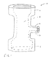
本発明は、HIP容器及びHIP容器を用いることにより得られるパーツを製造するための新しい有用な方法を提供する。図1は、金属粉末のHIP圧密により製造される弁体2の一例を示す。弁体2には、上部フランジ4と下部フランジ6があり、両フランジ間を延びる通路8がある。弁体2には、ハンドルポストを収容するための、雌ねじ部12を有するネック10もある。 The present invention provides a new and useful method for manufacturing HIP containers and parts obtained by using HIP containers. FIG. 1 shows an example of a valve body 2 manufactured by HIP consolidation of metal powder. The valve body 2 has an upper flange 4 and a lower flange 6, and a passage 8 extending between both flanges. The valve body 2 also has a neck 10 having an internal thread portion 12 for receiving a handle post.
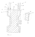
図2は、本発明に従って弁体2を製造するための第1HIP容器20の断面立面図を示す。この第1HIP容器20は、外側部22及び内側の中子24並びに両者の間にある空洞26を含む。空洞26の形状と大きさは、第1HIP容器20を用いて弁体2が製造されるようになっている。図示されている通り、第1HIP容器20には2つのポートがあり、HIPにより圧密された後で弁体2を構成することになる金属粉末を、第1ポート28と第2ポート30を介して空洞26の中に装填し、また、空洞26からガスを抽出することができる。空洞26での粉末の充填、及び/又は空洞26のガスの排出を行えるよう選択される設計特性に応じて、第1HIP容器20が単一又は任意の複数個のポートを含むことは、本発明の範囲内である。この典型的実施態様においては、ポート設計のバリエーションの一部が本発明に包含されることを示すために、第1ポート28と第2ポート30は異なる設計を有するものとして選択された。第1ポート28には、外側部22から突き出しているカラー32がある。カラー32は、真空ホースの取付けに適合するような長さと寸法を持つ溶接部38(破線で示す)によってカラー32に固定される圧着可能な管36(破線で示す)を受容するように適合している。第2ポート30は、真空ホースに適合するような長さと寸法を持つ圧着可能な管状の突起部40を含む。第1HIP容器20は、ガスを通さない被覆42も施すことができ、これは断面Aの拡大図に最もよく表されている。被覆42は、第1HIP容器20の外側を覆い、空洞30のガス排気時及び第1HIP容器20の熱間静水圧加圧成形時に空洞30へガスが漏えいするのを防ぐよう設計されている。被覆42のような被覆は、第1HIP容器20が相互に接続する多孔性であることにより空洞26において真空漏れを引き起こす、又は第1HIP容器20の熱間静水圧加圧成形時に空洞26にガスが入り込む可能性がある場合にのみ必要である。
FIG. 2 shows a sectional elevation view of a first HIP container 20 for producing the valve body 2 according to the invention. The first HIP container 20 includes an
第1HIP容器20は、本発明に従い、3次元印刷とその後の印刷後処理により製造される。第1HIP容器20を3次元印刷するために用いられる造形粉末は、3次元印刷プロセス、印刷された容器の印刷後処理、第1HIP容器20の空洞26の中に含まれることになる金属粉末、及びHIP条件に適合するよう選択される。例えば、造形粉末には、3次元プリンターの中で拡散され易く、その後強固な一体(モノリシック)物に焼結される、又はブロンズに焼結・浸透して強固な複合(コンポジット)物になることができるような粉末の大きさと分布を有する低炭素鋼粉末を選択することができる。低炭素鋼はまた、粉末が空洞26の中に充填されて空洞26からガスが排気された後に真空気密シールを形成する高温圧着に適している。低炭素鋼は室温では強固だが、一般的なHIP温度及び圧力条件の下では容易に流動するので、空洞26の中に含まれる金属粉末を固めて密度の高いパーツにすることができる。低炭素鋼はまた、空洞26の中の金属粉末を熱間静水圧加圧成形することにより作り出される弁体2から容易に機械で切削され、及び/又は化学的に除去される。 The first HIP container 20 is manufactured by three-dimensional printing and subsequent post-printing processing according to the present invention. The modeling powder used to three-dimensionally print the first HIP container 20 is a three-dimensional printing process, a post-printing treatment of the printed container, a metal powder that will be contained in the cavity 26 of the first HIP container 20, and Selected to meet HIP requirements. For example, the molding powder can be easily diffused in a three-dimensional printer and then sintered into a strong monolithic material, or sintered and infiltrated into bronze to become a strong composite material. It is possible to select a low carbon steel powder having such a powder size and distribution that can be obtained. Low carbon steel is also suitable for high temperature crimping where a powder is filled into the cavity 26 and a vacuum hermetic seal is formed after the gas is evacuated from the cavity 26. Low carbon steel is strong at room temperature, but easily flows under general HIP temperature and pressure conditions, so that the metal powder contained in the cavity 26 can be consolidated into a high density part. The low carbon steel is also easily machined and / or chemically removed from the valve body 2 created by hot isostatic pressing the metal powder in the cavity 26.
空洞26の中で圧密されることになる造形粉末と金属粉末の親和性は、造形粉末と接触することになる空洞26の表面部の性質を調整することにより高められてもよい。表面部の性質は、表面を相対的に不活性にする化学的手段によって当該表面を化学的に変化させることにより調整することができる。この調整は、表面を化学溶液、若しくは懸濁液に接触させる、表面を適切な温度で適切なガス、若しくは複数のガスの混合物に曝す、又はこれらの方法を組み合わせることにより行うことができる。表面の性質は、例えばアルミナや窒化ホウ素のような比較的不活性な物質によって当該表面を被覆することによっても調整することができる。この被覆は、適切な分散媒内で不活性物質の懸濁液に当該表面を曝すことにより施すことができる。表面の性質は、化学的手段の使用と被覆材の適用を組み合わせることにより調整することもできる。 The affinity between the modeling powder to be consolidated in the cavity 26 and the metal powder may be increased by adjusting the properties of the surface portion of the cavity 26 that will be in contact with the modeling powder. The nature of the surface portion can be adjusted by chemically changing the surface by chemical means that render the surface relatively inert. This conditioning can be done by contacting the surface with a chemical solution or suspension, exposing the surface to a suitable gas or mixture of gases at a suitable temperature, or a combination of these methods. Surface properties can also be adjusted by coating the surface with a relatively inert material such as alumina or boron nitride. This coating can be applied by exposing the surface to a suspension of inert material in a suitable dispersion medium. The surface properties can also be adjusted by combining the use of chemical means and the application of coatings.
オプションのガスを通さない被覆42は、使用される場合、第1HIP容器20の基底面にしっかりと付着しなければならない。被覆42は、HIP実施中の圧力と温度の下であっても気密シールを維持するために、当該基底面全体に広がって表面の多孔質を封止可能なものでなければならない。したがって、被覆42の厚さと材料特性はともに、注意を払って選択されなければならない。被覆42が単一の層、又は複数の層から成ることは、本発明の範囲内である。被覆42が複数の層から成る場合、それらの層は同じ材料である場合もあれば、異なる材料である場合もあり、後者の場合は、被覆42全体として上記の付着性と性能特性を有するように各材料が選択される。被覆42は、様々な方法、及び複数の方法の組み合わせによって施してよい。1つの方法は、電気めっき、若しくは無電解めっき、又はそれらの組み合わせにより、被覆42を施すものである。そのような被覆の一例には、厚さ約60〜100ミクロンのニッケルめっきした被覆がある。別の方法は、必要に応じて予熱及び望ましくない化学反応に対する任意の雰囲気保護を用いつつ、被覆材の溶融金属槽、又は1つ以上の被覆材の入った槽に第1HIP容器20を相次いで浸すことにより、被覆42を施すものである。別の方法は、プラズマ溶射付着により被覆を施すものである。これらの方法を2つ以上組み合わせて、被覆42を形成してもよい。被覆42の施工時には、適切な洗浄、及び例えば表面粗さの調整、一時的な界面層の施工などの表面処理を行うべきである。被覆42の形成時には、空洞26及びその表面の所望の清浄度を達成するために予防措置を講じるべきである。いくつかの実施態様において、被覆42は、空洞26表面の一部を覆う場合もあれば、表面全体を覆う場合もある。被覆42を施すための手段に関する追加情報は、1994年にASMインターナショナルが出版したASMの「HandbookVolume 5:Surface Engineering」(ISBN 978−0−87170−384−2)に記載されている。 If used, the optional gas impervious coating 42 must adhere firmly to the base surface of the first HIP container 20. In order to maintain a hermetic seal even under pressure and temperature during HIP operations, the coating 42 must be able to spread across the basal surface and seal the surface porosity. Accordingly, both the thickness and material properties of the coating 42 must be carefully selected. It is within the scope of the present invention for the coating 42 to consist of a single layer or multiple layers. When the coating 42 is composed of a plurality of layers, the layers may be the same material or different materials. In the latter case, the coating 42 as a whole has the above-mentioned adhesion and performance characteristics. Each material is selected. The coating 42 may be applied by various methods and combinations of methods. One method is to apply the coating 42 by electroplating, electroless plating, or a combination thereof. An example of such a coating is a nickel plated coating having a thickness of about 60-100 microns. Another method is to sequentially place the first HIP vessel 20 in a molten metal bath of coating material, or in a bath containing one or more coating materials, using optional pre-heating and optional atmospheric protection against undesirable chemical reactions. The coating 42 is applied by dipping. Another method is to apply the coating by plasma spray deposition. The coating 42 may be formed by combining two or more of these methods. When the coating 42 is applied, an appropriate cleaning and surface treatment such as adjustment of the surface roughness and temporary interface layer should be performed. When forming the coating 42, precautions should be taken to achieve the desired cleanliness of the cavity 26 and its surface. In some embodiments, the coating 42 may cover a portion of the surface of the cavity 26 or the entire surface. Additional information regarding the means for applying the coating 42 can be found in ASM's “Handbook Volume 5: Surface Engineering” (ISBN 978-0-87170-384-2) published by ASM International in 1994.
本発明を用いて、所望のパーツをHIPによって製造することができる。容器には、熱間静水圧加圧成形される所望のパーツになるよう構成され、寸法取りされた空洞が設けられる。容器の外面は、空洞に歪みのない静水圧を加えるべく、空洞に合うように設計される。空洞と外面の間の容器の肉厚は、当該容器を構成する材料、当該容器の設計、並びに製造及び処理時の当該容器の構造健全性を維持する必要性を考慮に入れて、可能な限り薄くなるように選択することが好ましい。好ましくは、肉厚は、約0.01インチ(0.25ミリメートル)〜0.5インチ(12.7ミリメートル)の範囲内である。 Using the present invention, the desired part can be manufactured by HIP. The container is provided with a dimensioned cavity configured to be the desired part to be hot isostatically pressed. The outer surface of the container is designed to fit into the cavity to apply an undistorted hydrostatic pressure to the cavity. The thickness of the container between the cavity and the outer surface should be as much as possible, taking into account the materials that make up the container, the design of the container, and the need to maintain the structural integrity of the container during manufacture and processing. It is preferable to select so as to be thin. Preferably, the wall thickness is in the range of about 0.01 inch (0.25 millimeter) to 0.5 inch (12.7 millimeter).
造形粉末の焼結は、固相焼結、反応焼結、過渡液相焼結、又は液相焼結により行うことができる。焼結に関する追加情報は、1996年にJohnWiley & Sonsにより出版されたRandal M. Germanによる「Sintering Theory and Practice」(ISPB 0−471−05785−X)に記載されている。 Sintering of the shaped powder can be performed by solid phase sintering, reaction sintering, transient liquid phase sintering, or liquid phase sintering. Additional information regarding sintering can be found in Randal M., published in 1996 by John Wiley & Sons. “Sintering Theory and Practice” (ISPB 0-471-05785-X) by German.
本明細書で特定される米国のすべての特許及び特許出願、米国外のすべての特許及び特許出願、並びにその他すべての文書は、法の下で認められる最大限の範囲で、本明細書内に省略せずに記載されているかの如く、参照により本明細書に組み込まれる。
All US patents and patent applications identified herein, all patents and patent applications outside the United States, and all other documents are within the scope of this specification, to the maximum extent permitted under law. As described without omission, it is incorporated herein by reference.
Claims (20)
造形粉末を以て容器(20)を3次元印刷することから成り、当該容器は粉末材料を受容するための空洞(26)と外面のある外側部(22)を有しており、当該空洞は表面を有し、当該空洞(26)内に粉末材料がある状態で当該容器(20)を熱間静水圧加圧成形することにより、当該容器(20)に囲まれた当該物品(2)が作り出されるような形状と大きさをしている
ことを特徴とする方法。 A method for producing a container (20) for forming an article (2) by hot isostatic pressing a powder material,
It consists of three-dimensional printing of the container (20) with shaped powder, the container having a cavity (26) for receiving the powder material and an outer part (22) with an outer surface, the cavity covering the surface And forming the article (2) surrounded by the container (20) by hot isostatic pressing with the powder material in the cavity (26). A method characterized by having a shape and size.
造形粉末を以て熱間静水圧加圧成形用容器(20)を3次元印刷し、当該容器(20)は粉末材料を受容するための空洞(26)と外面のある外側部(22)を有し、当該空洞(26)は表面を有し、当該空洞(26)内に粉末材料がある状態で当該容器を熱間静水圧加圧成形することにより、当該容器(20)に囲まれた当該物品(2)が作り出されるような形状と大きさをしており、
当該粉末材料を当該空洞(26)の中に装填し、
当該空洞(26)内に当該粉末材料がある状態で当該容器(20)を熱間静水圧加圧成形する
ステップから成る方法。 A method for producing an article (2) comprising:
A hot isostatic pressing container (20) is three-dimensionally printed with modeling powder, and the container (20) has a cavity (26) for receiving powder material and an outer part (22) with an outer surface. The article surrounded by the container (20) by forming the container with hot isostatic pressing under the condition that the cavity (26) has a surface and the powder material is in the cavity (26). (2) is shaped and sized to create
Loading the powder material into the cavity (26);
A method comprising the step of hot isostatic pressing the container (20) with the powder material in the cavity (26).
The method of claim 1, wherein the shaped powder comprises steel powder.
Applications Claiming Priority (3)
| Application Number | Priority Date | Filing Date | Title |
|---|---|---|---|
| US201361892078P | 2013-10-17 | 2013-10-17 | |
| US61/892,078 | 2013-10-17 | ||
| PCT/US2014/060572 WO2015057761A1 (en) | 2013-10-17 | 2014-10-15 | Three-dimensional printed hot isostatic pressing containers and processes for making same |
Publications (1)
| Publication Number | Publication Date |
|---|---|
| JP2016540887A true JP2016540887A (en) | 2016-12-28 |
Family
ID=52828629
Family Applications (1)
| Application Number | Title | Priority Date | Filing Date |
|---|---|---|---|
| JP2016523314A Pending JP2016540887A (en) | 2013-10-17 | 2014-10-15 | Three-dimensional printed hot isostatic pressing container and method for producing the same |
Country Status (4)
| Country | Link |
|---|---|
| US (1) | US20160243621A1 (en) |
| EP (1) | EP3057729A4 (en) |
| JP (1) | JP2016540887A (en) |
| WO (1) | WO2015057761A1 (en) |
Cited By (3)
| Publication number | Priority date | Publication date | Assignee | Title |
|---|---|---|---|---|
| JP2023066788A (en) * | 2021-10-29 | 2023-05-16 | 国立大学法人 東京大学 | METHOD FOR MANUFACTURING METAL ADDITIVE MOLDING PRODUCT |
| JP2023076470A (en) * | 2017-05-19 | 2023-06-01 | ボディコート エイチ.アイ.ピー.リミテッド | component |
| KR20230081817A (en) | 2021-11-29 | 2023-06-08 | 한국생산기술연구원 | Canning free hot isostatic pressure powder metallurgy method |
Families Citing this family (20)
| Publication number | Priority date | Publication date | Assignee | Title |
|---|---|---|---|---|
| KR101473900B1 (en) * | 2013-12-18 | 2014-12-18 | 한국항공우주연구원 | Metal core using direct metal rapid prototyping and manufacturing method of precision parts by hot isostatic press using the same and turbine blisk using the same |
| WO2015108891A1 (en) * | 2014-01-14 | 2015-07-23 | United Technologies Corporation | System and method for preventing powder depletion/contamination during consolidation process |
| US11434766B2 (en) * | 2015-03-05 | 2022-09-06 | General Electric Company | Process for producing a near net shape component with consolidation of a metallic powder |
| US20160279708A1 (en) * | 2015-03-26 | 2016-09-29 | Honeywell International Inc. | Net-shape or near-net shape powder metal components and methods for producing the same |
| US11117190B2 (en) * | 2016-04-07 | 2021-09-14 | Great Lakes Images & Engineering, Llc | Using thin-walled containers in powder metallurgy |
| GB2570618B (en) * | 2017-07-05 | 2021-05-19 | Bodycote H I P Ltd | Components |
| GB201721769D0 (en) * | 2017-12-22 | 2018-02-07 | Rolls Royce Power Eng Plc | A manufacturing method |
| EP3732019A1 (en) | 2017-12-31 | 2020-11-04 | Stratasys Ltd. | 3d printing of catalytic formulation for selective metal deposition |
| CN108220643B (en) * | 2018-01-29 | 2019-06-28 | 华中科技大学 | A kind of preparation method of tungsten particle reinforced amorphous matrix composite material |
| GB201802405D0 (en) * | 2018-02-14 | 2018-03-28 | Rolls Royce Plc | Method of manufacturing an object |
| US10955059B2 (en) | 2018-02-27 | 2021-03-23 | Delta Faucet Company | Faucet including dual water outlets |
| WO2019192633A1 (en) * | 2018-04-06 | 2019-10-10 | Hermle Maschinenbau Gmbh | Method for producing a component, capsule for hot isostatic pressing and component arrangement |
| US11498125B2 (en) * | 2018-10-31 | 2022-11-15 | Hamilton Sundstrand Corporation | Method for fabricating components using hybrid additive manufacturing and consolidation process |
| US10844969B2 (en) | 2018-12-28 | 2020-11-24 | Delta Faucet Company | Faucet including a rotatable spout arm |
| US11186973B2 (en) | 2018-12-28 | 2021-11-30 | Delta Faucet Company | Cantilevered faucet spout |
| FR3095147B1 (en) * | 2019-04-18 | 2022-07-08 | Safran Aircraft Engines | Method of manufacturing a turbomachine part |
| WO2021096517A1 (en) * | 2019-11-14 | 2021-05-20 | Halliburton Energy Services, Inc. | Additive manufacturing of components with functionally graded properties |
| WO2021126324A1 (en) * | 2019-12-17 | 2021-06-24 | Kennametal Inc. | Additive manufacturing techniques and applications thereof |
| CN112146439B (en) * | 2020-09-25 | 2021-10-22 | 同济大学 | A high temperature and high pressure gas-liquid combined sintering device and sintering method |
| US12172214B2 (en) * | 2022-09-26 | 2024-12-24 | Ge Infrastructure Technology Llc | Hot isostatic pressing container with enhanced directional consolidation |
Citations (4)
| Publication number | Priority date | Publication date | Assignee | Title |
|---|---|---|---|---|
| JPS52147509A (en) * | 1976-06-01 | 1977-12-08 | Special Metals Corp | Process and apparatus for production of solidifying element |
| JPH09262841A (en) * | 1996-03-26 | 1997-10-07 | Mitsuboshi:Kk | Production of hollow resin molded product and production of low melting point metal product used therein |
| JP2001522722A (en) * | 1997-09-30 | 2001-11-20 | アメテック・スペシャリティ・メタル・プロダクツ・ディビジョン | Static pressure processing method for gas |
| US20080237933A1 (en) * | 2003-06-16 | 2008-10-02 | Rainer Hochsmann | Methods and systems for manufacturing the manufacture of layered three-dimensional forms |
Family Cites Families (36)
| Publication number | Priority date | Publication date | Assignee | Title |
|---|---|---|---|---|
| US2751293A (en) * | 1951-07-31 | 1956-06-19 | Allied Prod Corp | Process of making perforated powdered metal article |
| US4212669A (en) * | 1978-08-03 | 1980-07-15 | Howmet Turbine Components Corporation | Method for the production of precision shapes |
| US5387380A (en) * | 1989-12-08 | 1995-02-07 | Massachusetts Institute Of Technology | Three-dimensional printing techniques |
| US5204055A (en) | 1989-12-08 | 1993-04-20 | Massachusetts Institute Of Technology | Three-dimensional printing techniques |
| US5490882A (en) | 1992-11-30 | 1996-02-13 | Massachusetts Institute Of Technology | Process for removing loose powder particles from interior passages of a body |
| US5775402A (en) | 1995-10-31 | 1998-07-07 | Massachusetts Institute Of Technology | Enhancement of thermal properties of tooling made by solid free form fabrication techniques |
| US5814161A (en) | 1992-11-30 | 1998-09-29 | Massachusetts Institute Of Technology | Ceramic mold finishing techniques for removing powder |
| US6146567A (en) | 1993-02-18 | 2000-11-14 | Massachusetts Institute Of Technology | Three dimensional printing methods |
| US6176874B1 (en) | 1993-10-18 | 2001-01-23 | Masschusetts Institute Of Technology | Vascularized tissue regeneration matrices formed by solid free form fabrication techniques |
| US5490962A (en) | 1993-10-18 | 1996-02-13 | Massachusetts Institute Of Technology | Preparation of medical devices by solid free-form fabrication methods |
| US5518680A (en) | 1993-10-18 | 1996-05-21 | Massachusetts Institute Of Technology | Tissue regeneration matrices by solid free form fabrication techniques |
| US6280771B1 (en) | 1997-02-20 | 2001-08-28 | Therics, Inc. | Dosage forms exhibiting multi-phasic release kinetics and methods of manufacture thereof |
| US5660621A (en) | 1995-12-29 | 1997-08-26 | Massachusetts Institute Of Technology | Binder composition for use in three dimensional printing |
| US6596224B1 (en) | 1996-05-24 | 2003-07-22 | Massachusetts Institute Of Technology | Jetting layers of powder and the formation of fine powder beds thereby |
| WO1998036738A1 (en) | 1997-02-20 | 1998-08-27 | Therics, Inc. | Dosage form exhibiting rapid disperse properties, methods of use and process for the manufacture of same |
| US5940674A (en) | 1997-04-09 | 1999-08-17 | Massachusetts Institute Of Technology | Three-dimensional product manufacture using masks |
| US6070973A (en) | 1997-05-15 | 2000-06-06 | Massachusetts Institute Of Technology | Non-resonant and decoupled droplet generator |
| WO1999015293A1 (en) | 1997-09-26 | 1999-04-01 | Massachusetts Institute Of Technology | Metal and ceramic containing parts produced from powder using binders derived from salt |
| US6397722B1 (en) | 1997-10-07 | 2002-06-04 | George D. Eddington | Variable torque accommodating, pressure fluid driven, transmissionless engine |
| DE69903800T2 (en) | 1998-03-18 | 2003-10-02 | Massachusetts Institute Of Technology, Cambridge | VASCULARIZED PERFUNDED ARRANGEMENTS FOR MICRO TISSUE AND MICROORGANES |
| US5939011A (en) * | 1998-04-06 | 1999-08-17 | Ford Global Technologies, Inc. | Method for producing a mandrel for use in hot isostatic pressed powder metallurgy rapid tool making |
| AU768641B2 (en) | 1998-10-12 | 2003-12-18 | Massachusetts Institute Of Technology | Composites for tissue regeneration and methods of manufacture thereof |
| US6042780A (en) | 1998-12-15 | 2000-03-28 | Huang; Xiaodi | Method for manufacturing high performance components |
| JP5178982B2 (en) | 2000-05-18 | 2013-04-10 | セリックス, インコーポレイテッド | Encapsulation of the toxic core in a non-toxic region in an oral dosage form |
| US6397922B1 (en) | 2000-05-24 | 2002-06-04 | Massachusetts Institute Of Technology | Molds for casting with customized internal structure to collapse upon cooling and to facilitate control of heat transfer |
| US6945638B2 (en) | 2001-10-29 | 2005-09-20 | Therics, Inc. | Method and system for controlling the temperature of a dispensed liquid |
| WO2003037244A2 (en) | 2001-10-29 | 2003-05-08 | Therics, Inc. | System for manufacturing controlled release dosage forms, such as a zero-order release profile dosage form manufactured by three-dimensional printing |
| CA2464478C (en) | 2001-10-29 | 2012-03-20 | Therics, Inc. | A system and method for uniaxial compression of an article, such as a three-dimensionally printed dosage form |
| DE60323482D1 (en) | 2002-05-06 | 2008-10-23 | Massachusetts Inst Technology | DIFFUSION CONTROLLED MEDICAMENT AND METHOD OF MANUFACTURE THROUGH THREE-DIMENSIONAL PRINTING |
| GB0307523D0 (en) * | 2003-04-01 | 2003-05-07 | Rolls Royce Plc | Hip manufacture of a hollow component |
| US7077334B2 (en) | 2003-04-10 | 2006-07-18 | Massachusetts Institute Of Technology | Positive pressure drop-on-demand printing |
| US7250134B2 (en) | 2003-11-26 | 2007-07-31 | Massachusetts Institute Of Technology | Infiltrating a powder metal skeleton by a similar alloy with depressed melting point exploiting a persistent liquid phase at equilibrium, suitable for fabricating steel parts |
| JP2007537007A (en) | 2004-05-12 | 2007-12-20 | マサチューセッツ インスティテュート オブ テクノロジー | Manufacturing methods such as three-dimensional printing including solvent vapor film formation |
| DK2236229T3 (en) | 2009-04-02 | 2015-10-05 | Sandvik Intellectual Property | A process for preparing a powder-based article |
| US20110052441A1 (en) * | 2009-08-27 | 2011-03-03 | General Electric Company | Method and device for hot isostatic pressing of alloyed materials |
| EP2551040A1 (en) * | 2011-07-25 | 2013-01-30 | EADS Deutschland GmbH | Method of manufacturing a component by hot isostatic pressing |
-
2014
- 2014-10-15 US US15/029,097 patent/US20160243621A1/en not_active Abandoned
- 2014-10-15 WO PCT/US2014/060572 patent/WO2015057761A1/en not_active Ceased
- 2014-10-15 EP EP14853308.6A patent/EP3057729A4/en not_active Withdrawn
- 2014-10-15 JP JP2016523314A patent/JP2016540887A/en active Pending
Patent Citations (4)
| Publication number | Priority date | Publication date | Assignee | Title |
|---|---|---|---|---|
| JPS52147509A (en) * | 1976-06-01 | 1977-12-08 | Special Metals Corp | Process and apparatus for production of solidifying element |
| JPH09262841A (en) * | 1996-03-26 | 1997-10-07 | Mitsuboshi:Kk | Production of hollow resin molded product and production of low melting point metal product used therein |
| JP2001522722A (en) * | 1997-09-30 | 2001-11-20 | アメテック・スペシャリティ・メタル・プロダクツ・ディビジョン | Static pressure processing method for gas |
| US20080237933A1 (en) * | 2003-06-16 | 2008-10-02 | Rainer Hochsmann | Methods and systems for manufacturing the manufacture of layered three-dimensional forms |
Cited By (4)
| Publication number | Priority date | Publication date | Assignee | Title |
|---|---|---|---|---|
| JP2023076470A (en) * | 2017-05-19 | 2023-06-01 | ボディコート エイチ.アイ.ピー.リミテッド | component |
| JP2023066788A (en) * | 2021-10-29 | 2023-05-16 | 国立大学法人 東京大学 | METHOD FOR MANUFACTURING METAL ADDITIVE MOLDING PRODUCT |
| JP7640432B2 (en) | 2021-10-29 | 2025-03-05 | 国立大学法人 東京大学 | Manufacturing method for metal additive manufacturing products |
| KR20230081817A (en) | 2021-11-29 | 2023-06-08 | 한국생산기술연구원 | Canning free hot isostatic pressure powder metallurgy method |
Also Published As
| Publication number | Publication date |
|---|---|
| WO2015057761A1 (en) | 2015-04-23 |
| EP3057729A4 (en) | 2017-10-18 |
| US20160243621A1 (en) | 2016-08-25 |
| EP3057729A1 (en) | 2016-08-24 |
Similar Documents
| Publication | Publication Date | Title |
|---|---|---|
| JP2016540887A (en) | Three-dimensional printed hot isostatic pressing container and method for producing the same | |
| US6354362B1 (en) | Method and apparatus for infiltrating preformed components and component assemblies | |
| EP2910324B1 (en) | Method for manufacturing a three-dimensional object using powders | |
| KR102297842B1 (en) | A method of making cermet or cemented carbide powder | |
| CN109689196B (en) | Multimaterial powder with composite particles for additive synthesis | |
| US9205492B2 (en) | Method for manufacturing a powder based article | |
| US6048432A (en) | Method for producing complex-shaped objects from laminae | |
| CN106862570A (en) | A kind of many shower nozzle Collaborative Control metal dust 3D forming methods | |
| US20160158843A1 (en) | Method of achieving full density binder jet printed metallic articles | |
| US11117190B2 (en) | Using thin-walled containers in powder metallurgy | |
| JP2018501398A (en) | Method for suppressing cavity deformation during heat treatment of three-dimensional printed material | |
| JPS6164801A (en) | Method for forming powders such as metals and ceramics | |
| WO2016030654A1 (en) | A mould for use in a hot isostatic press | |
| CN112789130A (en) | Method for producing a countermould and method for manufacturing a part with a complex shape using such a countermould | |
| KR20230121370A (en) | three-dimensional molded product and manufacturing method thereof | |
| CN104972114A (en) | Hot isostatic pressing integrated forming method of complex part with special functional layer | |
| JP2017514993A (en) | Method for manufacturing picklable metal components | |
| CN111690925B (en) | A kind of titanium and titanium alloy surface hardening and surface functionalization treatment process | |
| JP2726753B2 (en) | Method for forming coating on sintered layer | |
| CN107671294A (en) | Make high temperature insostatic pressing (HIP) jacket and the heat and other static pressuring processes of preformed member are produced using the jacket | |
| JPH04224603A (en) | Method and apparatus for preparing part with arbitrary and complicated shape | |
| EP3646970B1 (en) | Method for fabricating components using hybrid additive manufacturing and consolidation process | |
| JP4016106B2 (en) | Porous metal material and manufacturing method thereof | |
| WO2025179138A1 (en) | Method for densifying articles | |
| JPH07179907A (en) | Production of metallic material permeable to air and water |
Legal Events
| Date | Code | Title | Description |
|---|---|---|---|
| A621 | Written request for application examination |
Free format text: JAPANESE INTERMEDIATE CODE: A621 Effective date: 20160520 |
|
| A977 | Report on retrieval |
Free format text: JAPANESE INTERMEDIATE CODE: A971007 Effective date: 20170410 |
|
| A131 | Notification of reasons for refusal |
Free format text: JAPANESE INTERMEDIATE CODE: A131 Effective date: 20170523 |
|
| A521 | Request for written amendment filed |
Free format text: JAPANESE INTERMEDIATE CODE: A523 Effective date: 20170731 |
|
| A02 | Decision of refusal |
Free format text: JAPANESE INTERMEDIATE CODE: A02 Effective date: 20171213 |