JP2016538501A - Diesel engine fluid coolant system with solenoid operated gate valve - Google Patents
Diesel engine fluid coolant system with solenoid operated gate valve Download PDFInfo
- Publication number
- JP2016538501A JP2016538501A JP2016530948A JP2016530948A JP2016538501A JP 2016538501 A JP2016538501 A JP 2016538501A JP 2016530948 A JP2016530948 A JP 2016530948A JP 2016530948 A JP2016530948 A JP 2016530948A JP 2016538501 A JP2016538501 A JP 2016538501A
- Authority
- JP
- Japan
- Prior art keywords
- gate
- diesel engine
- fluid reservoir
- gate member
- reservoir system
- Prior art date
- Legal status (The legal status is an assumption and is not a legal conclusion. Google has not performed a legal analysis and makes no representation as to the accuracy of the status listed.)
- Granted
Links
Images


Classifications
-
- F—MECHANICAL ENGINEERING; LIGHTING; HEATING; WEAPONS; BLASTING
- F01—MACHINES OR ENGINES IN GENERAL; ENGINE PLANTS IN GENERAL; STEAM ENGINES
- F01P—COOLING OF MACHINES OR ENGINES IN GENERAL; COOLING OF INTERNAL-COMBUSTION ENGINES
- F01P7/00—Controlling of coolant flow
- F01P7/14—Controlling of coolant flow the coolant being liquid
-
- B—PERFORMING OPERATIONS; TRANSPORTING
- B60—VEHICLES IN GENERAL
- B60K—ARRANGEMENT OR MOUNTING OF PROPULSION UNITS OR OF TRANSMISSIONS IN VEHICLES; ARRANGEMENT OR MOUNTING OF PLURAL DIVERSE PRIME-MOVERS IN VEHICLES; AUXILIARY DRIVES FOR VEHICLES; INSTRUMENTATION OR DASHBOARDS FOR VEHICLES; ARRANGEMENTS IN CONNECTION WITH COOLING, AIR INTAKE, GAS EXHAUST OR FUEL SUPPLY OF PROPULSION UNITS IN VEHICLES
- B60K13/00—Arrangement in connection with combustion air intake or gas exhaust of propulsion units
- B60K13/04—Arrangement in connection with combustion air intake or gas exhaust of propulsion units concerning exhaust
-
- F—MECHANICAL ENGINEERING; LIGHTING; HEATING; WEAPONS; BLASTING
- F01—MACHINES OR ENGINES IN GENERAL; ENGINE PLANTS IN GENERAL; STEAM ENGINES
- F01N—GAS-FLOW SILENCERS OR EXHAUST APPARATUS FOR MACHINES OR ENGINES IN GENERAL; GAS-FLOW SILENCERS OR EXHAUST APPARATUS FOR INTERNAL COMBUSTION ENGINES
- F01N3/00—Exhaust or silencing apparatus having means for purifying, rendering innocuous, or otherwise treating exhaust
- F01N3/08—Exhaust or silencing apparatus having means for purifying, rendering innocuous, or otherwise treating exhaust for rendering innocuous
- F01N3/10—Exhaust or silencing apparatus having means for purifying, rendering innocuous, or otherwise treating exhaust for rendering innocuous by thermal or catalytic conversion of noxious components of exhaust
- F01N3/18—Exhaust or silencing apparatus having means for purifying, rendering innocuous, or otherwise treating exhaust for rendering innocuous by thermal or catalytic conversion of noxious components of exhaust characterised by methods of operation; Control
- F01N3/20—Exhaust or silencing apparatus having means for purifying, rendering innocuous, or otherwise treating exhaust for rendering innocuous by thermal or catalytic conversion of noxious components of exhaust characterised by methods of operation; Control specially adapted for catalytic conversion ; Methods of operation or control of catalytic converters
- F01N3/2066—Selective catalytic reduction [SCR]
-
- F—MECHANICAL ENGINEERING; LIGHTING; HEATING; WEAPONS; BLASTING
- F16—ENGINEERING ELEMENTS AND UNITS; GENERAL MEASURES FOR PRODUCING AND MAINTAINING EFFECTIVE FUNCTIONING OF MACHINES OR INSTALLATIONS; THERMAL INSULATION IN GENERAL
- F16K—VALVES; TAPS; COCKS; ACTUATING-FLOATS; DEVICES FOR VENTING OR AERATING
- F16K3/00—Gate valves or sliding valves, i.e. cut-off apparatus with closing members having a sliding movement along the seat for opening and closing
- F16K3/02—Gate valves or sliding valves, i.e. cut-off apparatus with closing members having a sliding movement along the seat for opening and closing with flat sealing faces; Packings therefor
- F16K3/029—Gate valves or sliding valves, i.e. cut-off apparatus with closing members having a sliding movement along the seat for opening and closing with flat sealing faces; Packings therefor with two or more gates
-
- F—MECHANICAL ENGINEERING; LIGHTING; HEATING; WEAPONS; BLASTING
- F16—ENGINEERING ELEMENTS AND UNITS; GENERAL MEASURES FOR PRODUCING AND MAINTAINING EFFECTIVE FUNCTIONING OF MACHINES OR INSTALLATIONS; THERMAL INSULATION IN GENERAL
- F16K—VALVES; TAPS; COCKS; ACTUATING-FLOATS; DEVICES FOR VENTING OR AERATING
- F16K3/00—Gate valves or sliding valves, i.e. cut-off apparatus with closing members having a sliding movement along the seat for opening and closing
- F16K3/02—Gate valves or sliding valves, i.e. cut-off apparatus with closing members having a sliding movement along the seat for opening and closing with flat sealing faces; Packings therefor
- F16K3/16—Gate valves or sliding valves, i.e. cut-off apparatus with closing members having a sliding movement along the seat for opening and closing with flat sealing faces; Packings therefor with special arrangements for separating the sealing faces or for pressing them together
- F16K3/18—Gate valves or sliding valves, i.e. cut-off apparatus with closing members having a sliding movement along the seat for opening and closing with flat sealing faces; Packings therefor with special arrangements for separating the sealing faces or for pressing them together by movement of the closure members
-
- F—MECHANICAL ENGINEERING; LIGHTING; HEATING; WEAPONS; BLASTING
- F16—ENGINEERING ELEMENTS AND UNITS; GENERAL MEASURES FOR PRODUCING AND MAINTAINING EFFECTIVE FUNCTIONING OF MACHINES OR INSTALLATIONS; THERMAL INSULATION IN GENERAL
- F16K—VALVES; TAPS; COCKS; ACTUATING-FLOATS; DEVICES FOR VENTING OR AERATING
- F16K31/00—Actuating devices; Operating means; Releasing devices
- F16K31/02—Actuating devices; Operating means; Releasing devices electric; magnetic
- F16K31/06—Actuating devices; Operating means; Releasing devices electric; magnetic using a magnet, e.g. diaphragm valves, cutting off by means of a liquid
- F16K31/0644—One-way valve
- F16K31/0668—Sliding valves
-
- B—PERFORMING OPERATIONS; TRANSPORTING
- B60—VEHICLES IN GENERAL
- B60K—ARRANGEMENT OR MOUNTING OF PROPULSION UNITS OR OF TRANSMISSIONS IN VEHICLES; ARRANGEMENT OR MOUNTING OF PLURAL DIVERSE PRIME-MOVERS IN VEHICLES; AUXILIARY DRIVES FOR VEHICLES; INSTRUMENTATION OR DASHBOARDS FOR VEHICLES; ARRANGEMENTS IN CONNECTION WITH COOLING, AIR INTAKE, GAS EXHAUST OR FUEL SUPPLY OF PROPULSION UNITS IN VEHICLES
- B60K11/00—Arrangement in connection with cooling of propulsion units
- B60K11/02—Arrangement in connection with cooling of propulsion units with liquid cooling
-
- B—PERFORMING OPERATIONS; TRANSPORTING
- B60—VEHICLES IN GENERAL
- B60K—ARRANGEMENT OR MOUNTING OF PROPULSION UNITS OR OF TRANSMISSIONS IN VEHICLES; ARRANGEMENT OR MOUNTING OF PLURAL DIVERSE PRIME-MOVERS IN VEHICLES; AUXILIARY DRIVES FOR VEHICLES; INSTRUMENTATION OR DASHBOARDS FOR VEHICLES; ARRANGEMENTS IN CONNECTION WITH COOLING, AIR INTAKE, GAS EXHAUST OR FUEL SUPPLY OF PROPULSION UNITS IN VEHICLES
- B60K15/00—Arrangement in connection with fuel supply of combustion engines or other fuel consuming energy converters, e.g. fuel cells; Mounting or construction of fuel tanks
- B60K15/03—Fuel tanks
- B60K2015/0321—Fuel tanks characterised by special sensors, the mounting thereof
-
- B—PERFORMING OPERATIONS; TRANSPORTING
- B60—VEHICLES IN GENERAL
- B60K—ARRANGEMENT OR MOUNTING OF PROPULSION UNITS OR OF TRANSMISSIONS IN VEHICLES; ARRANGEMENT OR MOUNTING OF PLURAL DIVERSE PRIME-MOVERS IN VEHICLES; AUXILIARY DRIVES FOR VEHICLES; INSTRUMENTATION OR DASHBOARDS FOR VEHICLES; ARRANGEMENTS IN CONNECTION WITH COOLING, AIR INTAKE, GAS EXHAUST OR FUEL SUPPLY OF PROPULSION UNITS IN VEHICLES
- B60K15/00—Arrangement in connection with fuel supply of combustion engines or other fuel consuming energy converters, e.g. fuel cells; Mounting or construction of fuel tanks
- B60K15/03—Fuel tanks
- B60K2015/03256—Fuel tanks characterised by special valves, the mounting thereof
- B60K2015/03302—Electromagnetic valves
-
- B—PERFORMING OPERATIONS; TRANSPORTING
- B60—VEHICLES IN GENERAL
- B60K—ARRANGEMENT OR MOUNTING OF PROPULSION UNITS OR OF TRANSMISSIONS IN VEHICLES; ARRANGEMENT OR MOUNTING OF PLURAL DIVERSE PRIME-MOVERS IN VEHICLES; AUXILIARY DRIVES FOR VEHICLES; INSTRUMENTATION OR DASHBOARDS FOR VEHICLES; ARRANGEMENTS IN CONNECTION WITH COOLING, AIR INTAKE, GAS EXHAUST OR FUEL SUPPLY OF PROPULSION UNITS IN VEHICLES
- B60K15/00—Arrangement in connection with fuel supply of combustion engines or other fuel consuming energy converters, e.g. fuel cells; Mounting or construction of fuel tanks
- B60K15/03—Fuel tanks
- B60K2015/03328—Arrangements or special measures related to fuel tanks or fuel handling
- B60K2015/03427—Arrangements or special measures related to fuel tanks or fuel handling for heating fuel, e.g. to avoiding freezing
-
- F—MECHANICAL ENGINEERING; LIGHTING; HEATING; WEAPONS; BLASTING
- F01—MACHINES OR ENGINES IN GENERAL; ENGINE PLANTS IN GENERAL; STEAM ENGINES
- F01N—GAS-FLOW SILENCERS OR EXHAUST APPARATUS FOR MACHINES OR ENGINES IN GENERAL; GAS-FLOW SILENCERS OR EXHAUST APPARATUS FOR INTERNAL COMBUSTION ENGINES
- F01N2610/00—Adding substances to exhaust gases
- F01N2610/02—Adding substances to exhaust gases the substance being ammonia or urea
-
- F—MECHANICAL ENGINEERING; LIGHTING; HEATING; WEAPONS; BLASTING
- F01—MACHINES OR ENGINES IN GENERAL; ENGINE PLANTS IN GENERAL; STEAM ENGINES
- F01N—GAS-FLOW SILENCERS OR EXHAUST APPARATUS FOR MACHINES OR ENGINES IN GENERAL; GAS-FLOW SILENCERS OR EXHAUST APPARATUS FOR INTERNAL COMBUSTION ENGINES
- F01N2610/00—Adding substances to exhaust gases
- F01N2610/10—Adding substances to exhaust gases the substance being heated, e.g. by heating tank or supply line of the added substance
- F01N2610/105—Control thereof
-
- F—MECHANICAL ENGINEERING; LIGHTING; HEATING; WEAPONS; BLASTING
- F01—MACHINES OR ENGINES IN GENERAL; ENGINE PLANTS IN GENERAL; STEAM ENGINES
- F01N—GAS-FLOW SILENCERS OR EXHAUST APPARATUS FOR MACHINES OR ENGINES IN GENERAL; GAS-FLOW SILENCERS OR EXHAUST APPARATUS FOR INTERNAL COMBUSTION ENGINES
- F01N2900/00—Details of electrical control or of the monitoring of the exhaust gas treating apparatus
- F01N2900/06—Parameters used for exhaust control or diagnosing
- F01N2900/18—Parameters used for exhaust control or diagnosing said parameters being related to the system for adding a substance into the exhaust
- F01N2900/1806—Properties of reducing agent or dosing system
- F01N2900/1811—Temperature
-
- F—MECHANICAL ENGINEERING; LIGHTING; HEATING; WEAPONS; BLASTING
- F01—MACHINES OR ENGINES IN GENERAL; ENGINE PLANTS IN GENERAL; STEAM ENGINES
- F01P—COOLING OF MACHINES OR ENGINES IN GENERAL; COOLING OF INTERNAL-COMBUSTION ENGINES
- F01P7/00—Controlling of coolant flow
- F01P7/14—Controlling of coolant flow the coolant being liquid
- F01P2007/146—Controlling of coolant flow the coolant being liquid using valves
-
- F—MECHANICAL ENGINEERING; LIGHTING; HEATING; WEAPONS; BLASTING
- F01—MACHINES OR ENGINES IN GENERAL; ENGINE PLANTS IN GENERAL; STEAM ENGINES
- F01P—COOLING OF MACHINES OR ENGINES IN GENERAL; COOLING OF INTERNAL-COMBUSTION ENGINES
- F01P2060/00—Cooling circuits using auxiliaries
- F01P2060/10—Fuel manifold
-
- Y—GENERAL TAGGING OF NEW TECHNOLOGICAL DEVELOPMENTS; GENERAL TAGGING OF CROSS-SECTIONAL TECHNOLOGIES SPANNING OVER SEVERAL SECTIONS OF THE IPC; TECHNICAL SUBJECTS COVERED BY FORMER USPC CROSS-REFERENCE ART COLLECTIONS [XRACs] AND DIGESTS
- Y02—TECHNOLOGIES OR APPLICATIONS FOR MITIGATION OR ADAPTATION AGAINST CLIMATE CHANGE
- Y02A—TECHNOLOGIES FOR ADAPTATION TO CLIMATE CHANGE
- Y02A50/00—TECHNOLOGIES FOR ADAPTATION TO CLIMATE CHANGE in human health protection, e.g. against extreme weather
- Y02A50/20—Air quality improvement or preservation, e.g. vehicle emission control or emission reduction by using catalytic converters
-
- Y—GENERAL TAGGING OF NEW TECHNOLOGICAL DEVELOPMENTS; GENERAL TAGGING OF CROSS-SECTIONAL TECHNOLOGIES SPANNING OVER SEVERAL SECTIONS OF THE IPC; TECHNICAL SUBJECTS COVERED BY FORMER USPC CROSS-REFERENCE ART COLLECTIONS [XRACs] AND DIGESTS
- Y02—TECHNOLOGIES OR APPLICATIONS FOR MITIGATION OR ADAPTATION AGAINST CLIMATE CHANGE
- Y02T—CLIMATE CHANGE MITIGATION TECHNOLOGIES RELATED TO TRANSPORTATION
- Y02T10/00—Road transport of goods or passengers
- Y02T10/10—Internal combustion engine [ICE] based vehicles
- Y02T10/12—Improving ICE efficiencies
Abstract
加熱要素と熱的連通状態にあるディーゼル排気流体のリザーバと、加熱要素に向うエンジンクーラント流体の流れのための第1の導管と、環境温度および/またはディーゼル排出流体の温度を検出するために配置された温度センサと、温度センサと通信可能に接続されかつスプラングゲートバルブと通信可能に接続されたコントローラーとを有するディーゼルエンジン流体リザーバシステム。ゲートバルブは、エンジンクーラント流体の流れの制御のための無流ポジションおよび流動ポジションを有し、かつ、流動ポジションにおいて導管ループと整列可能である、それを貫通する開口をそれぞれ有する第1のゲート部材および第2のゲート部材間に挟み込まれたエンドレス弾性材を含む。ディーゼル排気流体が凍結する送信された温度に応答して、コントローラーは流動ポジションとなるようにスプラングゲートバルブに信号を送る。A diesel exhaust fluid reservoir in thermal communication with the heating element, a first conduit for the flow of engine coolant fluid toward the heating element, and arranged to detect environmental temperature and / or diesel exhaust fluid temperature Engine fluid reservoir system having a programmed temperature sensor and a controller in communication with the temperature sensor and in communication with the sprang gate valve. The gate valve has a no-flow position and a flow position for control of the flow of engine coolant fluid, and first gate members each having an opening therethrough that is alignable with the conduit loop in the flow position. And an endless elastic material sandwiched between the second gate members. In response to the transmitted temperature at which the diesel exhaust fluid freezes, the controller signals the sprang gate valve to the flow position.
Description
本願は2013年11月12日に提出された米国仮出願第61/902,896号の利益を主張し、その全体はこの参照により本明細書中に組み込まれる。 This application claims the benefit of US Provisional Application No. 61 / 902,896, filed Nov. 12, 2013, which is hereby incorporated by reference in its entirety.
本願はディーゼルエンジン流体リザーバシステムに、特に、ディーゼルエンジン流体リザーバ加熱要素とエンジンとの間のエンジンクーラントの流れを選択的に制御するよう構成されたソレノイド駆動式ゲートバルブを有する、そのようなシステムに関する。 The present application relates to diesel engine fluid reservoir systems, and more particularly to such systems having a solenoid driven gate valve configured to selectively control the flow of engine coolant between the diesel engine fluid reservoir heating element and the engine. .
ディーゼルエンジンにおいては、低減されたエミッションレベルのための規制基準を満たすために、エンジンおよび車両製造業者は、排気中へ流体、ディーゼル排気流体(「DEF」)を注入する選択接触還元(「SCR」)システムを使用する。DEFは、通常、リザーバ内に貯蔵され、エンジン制御ユニットからの要求に応じて排気中に導入される。 しかしながら、DEFは、過度の低温にさらされた場合、凍結する傾向がある。それゆえ、DEFの凍結を防止するために、エンジンクーラントが、DFEを凍結しないように保つために、あるいはそれが既に凍結している場合にはDEFを解凍させるために、リザーバ内の加熱要素へと方向転換される。通常は電子的に制御される、ポペット、ダイアフラム、またはスプールバルブといったバルブが、主クーラントシステムからDEFを含むリザーバ内の加熱要素へのクーラントの流れを制御するための制御バルブとして使用されている。 In diesel engines, in order to meet regulatory standards for reduced emissions levels, engine and vehicle manufacturers use selective catalytic reduction (“SCR”) to inject fluid, diesel exhaust fluid (“DEF”) into the exhaust. ) Use the system. DEF is usually stored in a reservoir and introduced into the exhaust as required by the engine control unit. However, DEF tends to freeze when exposed to excessively low temperatures. Therefore, to prevent the DEF from freezing, the engine coolant keeps the DFE from freezing or, if it is already frozen, to the heating element in the reservoir to thaw the DEF. The direction is changed. Valves such as poppets, diaphragms, or spool valves, typically electronically controlled, are used as control valves to control the flow of coolant from the main coolant system to the heating element in the reservoir containing DEF.
電子的に制御されるポペット、ダイアフラムおよびスプールバルブは、動作可能ではあるが、望まれるように完全には機能しない。これらのタイプのバルブは汚染されやすく、しかも低い圧力損失が要求される場合には完全には機能しない。 Electronically controlled poppets, diaphragms, and spool valves are operable but do not function fully as desired. These types of valves are susceptible to contamination and do not function perfectly when low pressure loss is required.
自動化された、または「コマンド」バルブの中では、ゲートは、通常、ソレノイドによって作動させられ、ソレノイドコイルに印加される電流に応じて開閉される。これらのソレノイド駆動式ゲートバルブもまた、無給電の、「常時開」または「常時閉」ポジションに向かってゲートを付勢する、コイルスプリング、ダイアフラム、またはその他の付勢要素を含む傾向にある。付勢力は、その通常ポジションへと、それを復帰させるためにゲートの移動に抗する摩擦力に打ち勝つ必要があるために、そしてソレノイド機構は、能動的に給電された位置へとゲートを移動させるために、これらの同じ摩擦力および付勢力の両方に打ち勝つ必要があるために、摩擦力が、必要なソレノイド作動力の多くを決定する傾向にある。 Within an automated or “command” valve, the gate is typically actuated by a solenoid and opens and closes in response to the current applied to the solenoid coil. These solenoid-driven gate valves also tend to include coil springs, diaphragms, or other biasing elements that bias the gate toward a non-powered, “normally open” or “normally closed” position. The biasing force needs to overcome the frictional force that resists the movement of the gate to return it to its normal position, and the solenoid mechanism moves the gate to the actively powered position Thus, because both of these same frictional forces and biasing forces need to be overcome, the frictional forces tend to determine much of the required solenoid actuation force.
ゲートが閉じられた際の入口と出口との間の良好なシールは、通常、ゲートと導管の壁との間のある程度の干渉を必要とする。(特に妥当な許容範囲内でコンポーネント偏差を考慮したとき)信頼性の高い、高品質のシールを得るために設計の干渉を増加させることは、ゲートの移動に抗する摩擦力および必要なソレノイド作動力の両方を増大させる傾向がある。だが、シールの信頼性および品質を少ない摩擦抵抗を伴って維持できる場合、ソレノイド作動力の減少は、有益なことに、ソレノイド機構のサイズ、重量および放熱要求を、したがって全体としてゲートバルブのサイズ、重量および電力要求の低減を可能とするであろう。そうした改善されたゲートバルブが必要とされている。 A good seal between the inlet and the outlet when the gate is closed usually requires some degree of interference between the gate and the wall of the conduit. Increasing design interference in order to obtain a reliable, high quality seal (especially when considering component deviations within reasonable tolerances) is a frictional force that resists gate movement and the required solenoid performance. There is a tendency to increase both power. However, if the reliability and quality of the seal can be maintained with low frictional resistance, a reduction in solenoid actuation force beneficially reduces the size, weight and heat dissipation requirements of the solenoid mechanism, and thus the overall size of the gate valve, It will be possible to reduce weight and power requirements. There is a need for such an improved gate valve.
本明細書に開示されているのは、低減された作動力要求と共に、信頼性の高い、高品質のシールを提供するソレノイド駆動式ゲートバルブである。一態様では、ソレノイド駆動式ゲートバルブは、エンジンクーラントの流れを制御するために、したがってDEFの凍結を解除するために、エンジン冷却システムと、リザーバ内に保持されたDEFと熱的連通状態にある加熱要素との間の流体エンジンクーラント経路に組み込まれる。当該バルブはソレノイドコイルおよびバルブ機構に連結されたアーマチャーを含み、バルブ機構はスプラングゲートアセンブリのためのポケットを形成する導管を含み、これは、流動(開)ポジションと無流(閉)ポジションとの間でポケット内で直線移動可能である。スプラングゲートアセンブリは、第1のゲート部材と、この第1のゲート部材に対向する第2のゲート部材と、第1および第2のゲート部材間に保持されたエンドレス弾性帯とを含み、第1および第2のゲート部材は往復直線動作のためにアーマチャーに機械的に結合される。ある実施形態では、機械的結合はステムを含み、その上で第1および第2のゲート部材は少なくとも導管の長手方向軸線に平行な方向にそれぞれスライド可能であり、これは同じ方向であっても、あるいは互いに反対方向であってもよい。 Disclosed herein is a solenoid operated gate valve that provides a reliable, high quality seal with reduced actuation force requirements. In one aspect, the solenoid driven gate valve is in thermal communication with the engine cooling system and the DEF held in the reservoir to control the flow of engine coolant and thus to defreeze the DEF. Incorporated into the fluid engine coolant path between the heating elements. The valve includes an armature coupled to a solenoid coil and a valve mechanism, the valve mechanism including a conduit that forms a pocket for a sprung gate assembly, which has a flow (open) position and a no-flow (closed) position. It can move linearly in the pocket. The sprung gate assembly includes a first gate member, a second gate member facing the first gate member, and an endless elastic band held between the first and second gate members, And a second gate member is mechanically coupled to the armature for reciprocal linear motion. In some embodiments, the mechanical coupling includes a stem, on which the first and second gate members are each slidable in a direction parallel to at least the longitudinal axis of the conduit, which may be in the same direction. Or in opposite directions.
エンドレス弾性帯は、単一の、より硬質な材料から構成される一体型ゲートを圧縮することによって生成されるであろう大きな摩擦力を伴わずにスプラングゲートアセンブリがポケット内に締まり嵌めを形成することを可能とし、かつ、狭いコンポーネント公差の必要性を低減する。スライド可能な機械的結合は、ソレノイド機構および正確にゲートアセンブリと整列させられていない機械的結合により、スプラングゲートアセンブリが開ポジションと閉ポジションとの間で直線的に移動することを可能とし、ゲートアセンブリの移動に対する潜在的な摩擦抵抗をさらに低減する。当業者にとって、スライド可能な機械的カップリングは本発明の有益なさらなる任意の部分であることは明らかである。 The endless elastic band allows the sprung gate assembly to form an interference fit in the pocket without the large frictional forces that would be generated by compressing an integral gate composed of a single, harder material And reduce the need for narrow component tolerances. The slidable mechanical coupling allows the sparging gate assembly to move linearly between the open and closed positions by a solenoid mechanism and a mechanical coupling that is not precisely aligned with the gate assembly. Further reduce potential frictional resistance to assembly movement. It will be apparent to those skilled in the art that a slidable mechanical coupling is an additional useful part of the present invention.
以下の詳細な説明は本発明の一般的原理を示しており、その実例は添付図面に、さらに示されている。図面において、同様の参照番号は同一または機能的に類似の要素を示している。 The following detailed description illustrates the general principles of the invention, examples of which are further illustrated in the accompanying drawings. In the drawings, like reference numbers indicate identical or functionally similar elements.
本明細書で使用するように、「流体」とは、液体、懸濁液、コロイド、ガス、プラズマまたはそれらの組み合わせを意味する。 As used herein, “fluid” means liquid, suspension, colloid, gas, plasma, or combinations thereof.
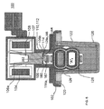
図2ないし図4は、それぞれ、図1に示すように加熱要素42とディーゼルエンジン14との間を流れるエンジンクーラント48の流れを選択的に制御するよう構成されたゲートバルブ100の一実施形態を示している。図1はディーゼルエンジンシステムに固有のものであるが、本明細書に開示されたゲートバルブは内燃エンジン内のその他のシステムを含む多くのシステムに組み込まれてもよく、ただし、ゲートバルブ100は図1のシステムに汚染許容範囲を含む多くの利点を提供する。図1の概略図を参照すると、ディーゼルエンジンシステム10が示されており、これは、DEF18を含むリザーバ16を有するディーゼル排気流体システム12を含む。加熱要素42は、DEF18および加熱要素42が良好な熱伝達状態に置かれるようにリザーバ16に取り付けられている。高圧エンジンクーラントは、それを通る流体の流れを制御するために、第1の導管20によって形成される流路内に作用的に配置されたゲートバルブ100を含む第1の導管20を通ってフィッティング44から流れる。ディーゼルエンジンシステム10はまた、ディーゼルエンジン14と、リザーバ16に取り付けられた加熱要素42との間の第2の流路を形成する第2の導管22を含む。リザーバ16は、DEF吸引ライン26およびDEFリターンライン28によって計量ポンプ24に対して流体的に結合され、そして計量ポンプ24は、計量制御モジュール30に対して作用的に、かつ、DEF圧力ライン34によってDEFインジェクター32に対して流体的に結合される。DEFインジェクター32は、ディーゼルエンジン14の排気流38内のSCR触媒コンバーター36の上流側に流体的に結合される。ディーゼルエンジンシステム10はまた、ディーゼルエンジン14とSCR触媒コンバーター36との間の排気流38中に、通常はDEFインジェクターの上流側に、ディーゼルパティキュレートフィルター40を含んでもよい。リーンNOxトラップ、酸化触媒、水素発生触媒ならびにこれらおよびその他の組み合わせといった、その他の触媒コンパートメントが組み込まれてもよい。
2-4 each illustrate one embodiment of a
依然として図1を参照すると、ゲートバルブ100は二つの状態、すなわち(1)無流状態および(ii)流動状態を持つ。計量制御モジュール30、またはディーゼルエンジン14に取り付けられたエンジン制御コンピュータは、温度センサ50を用いて、周囲温度、およびまたはDEF18の温度のいずれかを検出する。周囲またはDEF18の温度がDEFの凍結温度を下回るとき、ゲートバルブ100には流動状態となるように指令が出される。これによってエンジンクーラント48が加熱要素42を通って流れることが可能となる。エンジン温度がDEFの凍結温度を上回って上昇するとき、DEF18は溶融し、ポンプ輸送可能となる。温度センサ50によって測定されたDEF18の温度が特定の温度に達した後、ゲートバルブ100には無流状態となるように指令が出される。一実施形態では、ゲートバルブ100は、無流状態のためのパワーオフ形態および流動状態のためのパワーオン形態を有する。別の実施形態では、パワーオフおよびパワーオフは逆にされてもよい。
Still referring to FIG. 1, the
ここで図2〜4を参照すると、ゲートバルブ100は、バルブ機構120を作動させるソレノイドコイル104およびアーマチャー106を収容するハウジング102を有することができる。アーマチャー106は、ソレノイドコイル104内に収容された挿入端部106aと、コイルに電流を加えた際にソレノイドコイル104内により完全に収容される隣接ボディ部分107とを含む。ある構造では、挿入端部106aおよびボディ部分107は、磁性または常磁性材料、例えば鉄含有合金またはフェライト含有複合材料から製造されたシリンダーであってもよい。ここでは、アーマチャー106およびソレノイドコイル104は、バルブ機構120に作用する付勢力および摩擦力に打ち勝つのに十分な力を発生するように形作られかつ構成される。
Referring now to FIGS. 2-4, the
一実施形態では、そうした形状および構造は、挿入端部106aと、引き込み力の漸進的増大を実現するためにボディ部分107の方向に挿入端部106aから先細になる内部リセス108を有するシリンダーであるボディ部分107を含むことができる。テーパーは、引き込み力が付勢要素110によって生み出される反対向きの付勢力よりも大きくなるように構成されてもよい。図2に示すように、付勢要素110は、アーマチャー106のボディ部分107を取り囲むと共にソレノイドコイル104および非挿入端部106bの両方に当接するコイルスプリング112であってもよいが、この付勢要素は、非挿入端部106bに当接するか結合されたダイアフラムあるいはフラットスプリング、非挿入端部106bに当接するか結合されたリーフスプリングなどであってもよいことを理解されたい。ソレノイドが、代替的に、その他の付勢要素を含む双安定ソレノイドであってもよいこともまた当業者にとって明らかである。
In one embodiment, such a shape and structure is a cylinder having an
バルブ機構120は、やはり導管122によって形成されたポケット126を通る開口124を形成する導管122と、それを貫通する少なくとも一つの通路129を有するスプラングゲートアセンブリ128とを含むことができる。スプラングゲートアセンブリ128(図2〜6)は、図3に示すように、スプラングゲートを流動状態に置くためにポケット126内で直線的に移動可能であり、この状態では開口124は、流体が導管122を通って入口端部122aから出口端部122bへとまたはその逆に流れることを可能とするために、少なくとも部分的に通路129と整列させられる。一実施形態では、流動状態は、開口124と実質的に整列させられたスプラングゲートアセンブリ128の通路129を有する。閉状態では、図4に示すように、スプラングゲートアセンブリ128は流体が開口124を通過するのを阻止する。
The
図3および図4に示すように、導管122は、両端から開口124に向かって長手方向軸線「A」に沿って連続的に漸進的に先細になるかあるは幅狭になり、これによって開口124に本明細書では断面プロファイル125と呼ばれる、その最小内径を有するチューブであってもよい。この断面プロファイル125はゲートバルブ100を横切る圧力降下を最小限に抑える。その他の構造では、導管122は、その全長に沿って均一な内径を有していてもよい。図示された構造において、長手方向軸線「A」に垂直な断面は円形であるが、変形例においては、断面127は(均一または先細になる横および共役直径を有する)楕円形あるいは(均一または先細になる固有幅を有する)多角形などであってもよい。図面に示される導管122は一つの入口と一つの出口とを有するが、これは限定として解釈すべきではない。別の実施形態では、導管122は、二つの入口および一つの出口、または二つの出口および一つの入口、または一つの入口、一つの出口およびブラインド接続部を有していてもよい。
As shown in FIGS. 3 and 4, the
図2〜4の実施形態では、スプラングゲートアセンブリ128は、内部リセス108内から突出するステム114によって機械的にアーマチャー106に結合される。代替実施形態では、ステム114は、ソレノイドコイル104およびアーマチャー106がステムをバルブ機構120および開口124に向って引っ張るように構成されるか、あるいはそれらから離れるように引っ張るように構成されるかに依存して、アーマチャー106の挿入端部106aから、あるいはアーマチャー106の非挿入端部から突出していてもよい。図4および図5の実施形態に示されるように、ソレノイドコイル104、アーマチャー106、付勢要素110およびステム114の相対的な配置は、(以下でさらに説明するように、スプラングゲートアセンブリ128の細部構成に依存して)常時閉バルブから常時開バルブへとまたはその逆へとゲートバルブ100を変化させるために変更することができる。ソレノイドは、ゲートバルブ100を動作させるために、(1)直流電圧、(2)パルス幅変調(PWM)、または(3)ピーク・ホールド制御を利用可能である。ピーク・ホールドソレノイド(飽和スイッチソレノイドとしても知られる)は、より速い作動時間、低い平均電力消費、低い発熱量、および/またはより小さなパッケージサイズが望まれる場合に有効である。常時閉あるいは常時開ポジション間でゲートバルブ100を作動させる他に、ゲートバルブは、複数の部分的開/部分的閉ポジションの比例制御のために動作させられてもよい。ある構造では、ステム114はアーマチャー106からの一体的突起であってもよいが、別な構造では、ステムは、別のもの、好ましくは非磁性材料から製造された固定突起であってもよい。一実施形態では、電磁石が、所望のポジションへとアーマチャー106を引っ張るべく、吸引力のみを加えるために組み込まれてもよい。アーマチャーを別の位置へと移動させるためにスプリングが組み込まれてもよい。ソレノイドの動作には、その行程の終点でアーマチャー106を拘束するために永久磁石を利用することもできる。
In the embodiment of FIGS. 2-4, the sprung
ステムの接続開口端部114aはスプラングゲートアセンブリ128に固定されてもよいが、機械的カップリングは、好ましくは、少なくとも導管の長手方向軸線と平行な方向にスプラングゲートアセンブリに対してスライド可能である。ある構造では、機械的カップリングは、長手方向軸線Aと平行な方向にステム114およびスプラングゲートアセンブリ128間の相対的なスライド移動を可能にするレールシステム160を含む。このスライド可能な機械的カップリングは、ソレノイドコイル104およびアーマチャー106が、導管122のいずれかの端部に向かってゲートアセンブリを引っ張ることなく、ポケット126内でスプラングゲートアセンブリ128を直線移動させるように動作することを可能とする。ソレノイドコイル104、アーマチャー106および/またはステム114の、バルブ機構120との完全ではない整列は、さもなければ、その経路からスプラングゲートアセンブリ128を傾けるようとし、したがってゲートアセンブリと導管122の壁との間の摩擦力を増大させようとするであろう。
Although the stem connection
レールシステム160は、図5および図6の断面を参照することによって、より良く理解できるが、これらは導管122の長手方向軸線Aに対して交差している。レールシステム160は、その対向する側面に配置されたレースウェイ溝またはレッジ164を備えた、ステムの接続開口端部114a付近に配置されたガイドレール162を含む。スプラングゲートアセンブリ128の上側端部128a(ソレノイドコイル104およびアーマチャー106に近い端部)は、これに対応して、ガイドレール162を包み込みかつレースウェイ溝164内に突出するよう構成されたスライダー166を含む。一実施形態では、ガイドレール162は、スライダー166がその上に載るためのラットフォームあるいはレッジ164を形成するプレート状部材167(図5および図6)で終端してもよい。変形構造では、レールシステムは、ガイドレールおよびレーストラック溝(図示せず)を形成するステム114aの一部としてのスライダーおよびスプラングゲートアセンブリ128の上側端部128aを伴って、逆にされてもよい。
The
図4のみに見られるように、バルブ機構120は、任意選択で、スプラングゲートアセンブリ128を越えてポケット126内に漏れる流体を排出するために、ポケット126と流体連通するベントポート170を含んでもよい。図4において、ベントポート170は、アーマチャー106と開口124との間に配置されたポケット126の一部と流体連通しているが、これに限定されるものではない。ベントポート170は、流体がポケット126から導管の入口端部122aへと流れることを可能とするために、導管122の内部に開口していてもよい。
As seen only in FIG. 4, the
以下でさらに説明するスプラングゲートアセンブリ128の異なる実施形態は、いくつかの用途のためにより適しているであろう。さらに、当業者にとって、ゲートバルブ100が非自動車用途を含むその他の用途において、そして空気以外の流体と共に使用可能であることは明らかである。
Different embodiments of the sprung
図7〜9を参照すると、概して参照数字228で示されたスプラングゲートアセンブリの第1実施形態が示されている。スプラングゲートアセンブリ228は、第1のゲート部材230、第2のゲート部材232、そして第1および第2のゲート部材230,232間に収容されたエンドレス弾性帯234を含む。エンドレス弾性帯234は、第1および第2のゲート部材230,232間に挟み込まれるものとして説明することができる。図9から分かるように、第2のゲート部材232は、その内面252の一部の周りに、エンドレス弾性帯の一部を収容するためのトラック236を含む。図7〜9では認識できないが、第1のゲート部材230もまたトラック236を含む。
With reference to FIGS. 7-9, a first embodiment of a sprung gate assembly, generally designated by the
第1および第2のゲート部材230,232は、同一または実質的に類似の部材であってもよいが、本質的にこの様式に限定されるものではない。図7および図9に示すように。第1および第2のゲート部材230,232は同一であってもよく、したがって導管122の入口端部122aまたは出口端部122bのいずれかに面して配置することができる。これは、導管122内での流体の流れの方向に関係なく、同じような性能を有するバルブをもたらす。
The first and
特に図7および図9を参照すると、第1および第2のゲート部材230,232はいずれも、協働で通路229を形成する開口233をそれ自体に有する。図3に示すような開ポジションでは、スプラングゲートアセンブリ228を通過する通路229は、流体がそれを通って流れることができるように導管122と整列させられる。通路229を有するゲートの一部は、本明細書では、開ポジション部分240(図7)と呼ばれ、そして、スライダー266を有する上側端部228aの反対側に示された隣接部分は、ゲート228のこの部分が閉ポジションへと移動させられたときそれを通過する流体の流れを阻止するために導管122を塞ぐので閉ポジション部分242と呼ばれる。この実施形態における各ゲート部材230,232の閉ポジション部分242は、実質的に滑らかな連続的な外面250を有する。当業者にとって、常時閉から常時開へと(またはその逆へと)ゲートバルブ設計を変更する第2の手段を提供して、開ポジション部分240が接続開口端部228aと反対側にあるように、開ポジションおよび閉ポジション部分240,242を逆にすることが可能であることは明らかである。本明細書に開示されたスプラングゲートアセンブリは閉ポジション部分および開ポジション部分を有するものとして示されているが、別な実施形態では、異なる度合の開ポジション部分および少なくとも一つの閉ポジション部分を形成する二つ以上の部分を有していてもよい。一実施形態では、導管122は、少なくとも三つの異なるポジション部分を有するスプラングゲートアセンブリとの組み合わせで、二つの入口および一つの出口を有することができる。
With particular reference to FIGS. 7 and 9, the first and
この第1の実施形態において、エンドレス弾性帯234は略楕円形に成形されており、これによってオープンスペースを形成する内周282と、外周284と、対向する第1および第2の側面286,288を含む。エンドレス帯234は、第1の側面286が一方のトラック236内に収容され、かつ、第2の側面288が他方のトラック236内に収容された状態で、第1および第2のゲート部材230,232のトラック236内に収容される。エンドレス帯234が第1および第2のゲート部材230,232のトラック236内に収容されたとき、第1および第2のゲート部材230,232は距離D(図7)だけ互いに離間させられる。トラック236は、エンドレス弾性帯234を、同様にゲート部材の外周からある距離だけ奥まった位置に置くように配置される。図8から分かるように、この構成は、第1および第2のゲート部材230,232間でエンドレス弾性帯234の外面の周りにチャネル254を形成する。チャネル254は、ポケット126内のスプラングゲート228の周りの流体の流れをもたらす。ベントポート170(図4)が存在する場合、チャネル254は流体がポケット内で変位させられかつベントポート170を介して出て行くことを可能とし得る。チャネル254を介したこのベントは、概して、導管122を通る流体の流れの方向に略垂直であり、アーマチャー106がゲートをポケット内により完全に移動させるときポケットから流体を排出する。
In this first embodiment, the endless
エンドレス弾性帯234は、第1および第2のゲート部材230,232間で圧縮可能であり、したがって導管122を通る流れの方向と平行に作用するスプリングとして機能する。さらに、エンドレス弾性帯234は、このエンドレス弾性帯234と第1および第2のゲート部材230,232におけるトラック236の外壁部との間にシールを形成するために、導管122を通って流れる流体によってエンドレス弾性帯234に加えられる力に応答して、半径方向外側に拡張可能である。
The endless
作動時、図3に示すような開ポジションにおいては、導管を通って流れる流体は、左から右へ流れるにせよ、右から左へ流れるにせよ、スプラングゲートアセンブリ228内の通路229を通り、そして流体の圧力は、半径方向外側に向うエンドレス弾性帯234に作用する力を与え、これによってトラック236の外周とシーリング係合するようにエンドレス弾性帯を押圧する。このシーリング係合はコネクター開口124およびポケット126内への流体の漏れを低減または防止し、これによってスプラングゲートアセンブリ228は単一材料の均等に硬質なゲートよりも、より耐漏れ性に優れたものとなる。
In operation, in the open position as shown in FIG. 3, the fluid flowing through the conduit, whether flowing from left to right or flowing from right to left, passes through the
エンドレス弾性帯234はまた、このエンドレス弾性帯の存在により、特にポケット126の寸法およびゲート部材230,232の厚さに関して、製造公差の影響を受けにくいゲートを形成する。ポケット126は、通常、締まり嵌めを生じるようにスプラングゲートアセンブリ228の無負荷の幅よりも小さい幅を有するように形成される。スプラングゲートアセンブリ228において、エンドレス弾性帯234は、スプラングゲート228がポケット126内に挿入されたとき、第1および第2のゲート部材230,232間で圧縮状態となる。ポケット126内に挿入された(押し込まれた)際に第1および第2のゲート部材230,232へのエンドレス弾性帯のスプリング力は、漏れを低減または防止するためにポケットの壁とシーリング係合状態となるように、それぞれのゲート部材を押圧する。最も重要なことに、硬質ゲート部材230,232のそれに、または単一の剛性ゲートのそれに対する、エンドレス弾性帯の実質的に低い弾性率は、スプラングゲートアセンブリ228に作用する垂直力およびその経路に沿ったアセンブリの直線移動に抗する摩擦力が実質的に僅かであることを意味する。これは、摩擦力(摩擦力は垂直力と摩擦係数の積に等しい)を、したがって必要なソレノイド駆動力を低減する。この利点は、以下で説明するその他の実施形態にも等しく適用可能である。
The endless
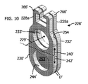
ここで図10および図11を参照すると、概して参照数字228’によって示されたスプラングゲートアセンブリの第2実施形態が提示され、これは、同様に、第1のゲート部材230’と、第2のゲート部材232’と、第1および第2のゲート部材230’,232’間に収容されたエンドレス弾性帯235’とを含む。エンドレスの弾性帯235’は、第1および第2のゲート部材230’,232’間に挟み込まれるものとして説明することができる。図11から分かるように、第2のゲート部材232’は、エンドレス弾性帯235’の一部を受け容れるために、その内面252’の一部の周りにトラック237’を含む。図10および図11では認識できないが、第1のゲート部材230’はまたトラック237’を含む。両方のゲート部材230’,232’は、上述したように、アーマチャー106に対してゲートアセンブリ228’をスライド可能に結合するためのスライダー266’を有する上側端部228aを有する。だが、上述したように、全てのそうした実施形態において、部材230,230’,232,232’等は、ステム114のガイドレール162およびレーストラック溝164と同様のガイドレールおよびレーストラック溝を交替で含むことができる。
Referring now to FIGS. 10 and 11, a second embodiment of a sprung gate assembly, generally indicated by reference numeral 228 ', is presented, which also includes a first gate member 230' and a second It includes a
ここで、図11に示すように、エンドレス弾性帯235’は、概して、弾性材料の8の字形状の帯であり、したがって第1のオープンスペースを形成する第1の内周272と、第2のオープンスペースを形成する第2の内周273と、外周274と、対向する第1および第2の側面276,278とを含む。エンドレス弾性帯235は、第1の側面276が一方のトラック237’内に収容されかつ第2の側面278が他方のトラック237’内に収容された状態で、第1および第2のゲート部材230’,232’のトラック237’内に収容される。エンドレス弾性帯235が8の字形状であるので、トラック237’もまた通常は8の字形状である。エンドレス弾性帯235’が第1および第2のゲート部材230’,232’のトラック237’内に着座させられたとき、第1および第2のゲート部材230’,232’は距離D’(図10)だけ互いに離間させられる。トラック237は、図7〜9を参照して先に説明したように、ベントを実現するために、エンドレス弾性帯235’を第1および第2のゲート部材230’,232’の外周からある距離だけ奥まった位置に置くように配置される。
Here, as shown in FIG. 11, the endless
第1および第2のゲート部材230’,232’は互いに構造的に異なるが、両者は、流体がそれを通って流れることを可能とするために、開ポジションにおいては導管122と整列させられる通路229’を協同で形成する第1の開口233’をそれ自体に有する。ゲートのこの部分は開ポジション部分240’(図10)と呼ばれ、そしてスライダー266’と反対側のそれに隣接する部分は、スプラングゲートアセンブリ228’のこの部分は閉ポジションへと移動させられたときそれを通過する流体の流れを阻止するために導管122を塞ぐので、閉ポジション部分242’と呼ばれる。この実施形態において、第1のゲート部材230’の閉ポジション部分242’は、それを貫通する第2の開口244’を含む。第2の開口は、第1の開口233’と実質的に同じ寸法とされてもよい。第2のゲート部材232’は、その閉ポジション部分242’に第2の開口を含んでいない。代わりに、第2のゲート部材232’の閉部分242’は実質的に連続した滑らかな外面を有する。第2のゲート部材232’は、任意選択で、エンドレス弾性帯235’によって形成された第2のオープンスペースの寸法内に嵌るよう構成されると共にエンドレス弾性帯235’の第2の内周273よりも小さな開口を形成する少なくとも第1のゲート部材230’における第2の開口244’のサイズとなるような寸法とされた、その内面252’から突出するプラグ253’を含んでいてもよい。プラグ253’は、第2のゲート部材232’の内面252’の実質的に滑らかな部分であってもよい。
Although the first and second gate members 230 ', 232' are structurally different from each other, they are both passages that are aligned with the
開ポジションにおいて、通路229’を通って流れる流体は、半径方向外側に向けられたエンドレス弾性帯235’に作用する力を提供し、これによってエンドレス弾性帯をトラック237’の外周とのシーリング係合状態となるように押圧する。このシーリング係合はポケット126内への流体の漏れを低減または防止し、これは、図10および図11の実施形態におけるゲート228’を単一材料の均等に硬質なゲートよりも、より耐漏れ性に優れたものとする。
In the open position, the fluid flowing through the passage 229 'provides a force acting on the radially outwardly directed endless elastic band 235', thereby sealing the endless elastic band with the outer periphery of the track 237 '. Press to be in a state. This sealing engagement reduces or prevents fluid leakage into the
閉ポジションにおいて、導管122内の流体の流れは、第1のゲート部材230’によって形成されたスプラングゲート228’の側に向かう方向であってもよく、すなわち第1のゲート部材230’はゲートバルブ100の入口端部122aに面していてもよい。特に、流れのこの方向は、導管122がフィッティング44からの高圧エンジンクーラントに接続される場合に有益である。これは、クーラント圧力が、第2の開口244を通過すると共に、第1および第2のゲート部材230’,232’のトラック237’に対して、それを密封係合させるためにエンドレス弾性帯に半径方向外側に作用するようにエンドレス弾性帯235’の第2の内周273に向ってプラグ253’によって案内されるので、そうである。第2の開口244’の存在はまた、その上にクーラント圧力が、エンドレス弾性帯235’を軸方向に圧縮するために導管122内の流れ方向と平行に作用する力を加えることができる第1のゲート部材230’の外面の表面積を最小にする。クーラント圧力が軸方向にエンドレス弾性帯235’を圧縮しない場合、ゲート部材230’,232’の一方が他方に近づくように移動し、Dを減少させ、そしてポケット126の一方の壁と、それを通って流体が漏れる可能性があるゲート部材との間にギャップを形成する。これは望ましくない結果である。したがって、ゲート部材228’に関して、第2のゲート部材232’の実質的に連続した滑らかな外面に影響を与えるであろう方向へ導管内にクーラント圧力が流れ込むのは望ましくないであろう。
In the closed position, the flow of fluid in the
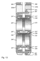
ここで図12〜14を参照すると、このまたはその他の実施形態において、ゲート部材230’,232’の一方は図10および図11のものである。ここで、スプラングゲートアセンブリ228’はラッチ281を含み、かつ、ゲート部材230’,232’の他方は対応するように配置されたデテント283を含むことができる。図示するように、一方が複数のラッチ281を含んでいてもよくかつ他方が複数のデテントを含んでいてもよく、あるいはそれぞれが、ラッチ281およびデテント283が、その相手方要素の配置に対応するように部材230’,232’の両端に配置された状態で、一つのラッチ281および一つのデテント283を含んでいてもよい。ラッチ281およびデテントは、ポケット126内への挿入前に組み立てられた状態でアセンブリを積極的に保持することにより、スプラングゲートアセンブリ228’(または128,228等)の組み立てを助ける。また、このまたはその他の実施形態の変形例では、ゲート部材230’,232’は、図5および図6に示すステム114のヘッド167の周りにカチッと嵌るマルチパートソケット268を協働で形成できる。マルチパートソケット268は、ポケット126内への挿入前にステム114上でアセンブリを積極的に保持することにより、スプラングゲートアセンブリ228’(または128,228等)の組み立てを助ける。マルチパートソケット268は、スライドゲートアセンブリ228’の直線動作の経路に垂直な複数の方向へのスライド移動を可能とするために、ステム117のヘッド167の周りにスナップフィット機能を使用してカチッと嵌ることができる。
Referring now to FIGS. 12-14, in this or other embodiments, one of the gate members 230 ', 232' is that of FIGS. Here, the sprung gate assembly 228 'may include a
ここで図15〜17を参照すると、(第1または第2のゲート部材のいずれかに向って案内される流れと連係動作可能な)ユニバーサルスプラングゲートアセンブリが図示されており、参照数字328で示されている。ユニバーサルスプラングゲート328は、図10および図11の実施形態と同様の第1のゲート部材230’と、第1のゲート部材230’と同じ一般的構造を有する第2のゲート部材332’と、閉ポジションのために必要な障害物を提供するインナーゲート部材334と、第1のゲート部材230’とインナーゲート部材334との間に形成されたトラック内に配置された第1のエンドレス弾性帯346と、第2のゲート部材332とインナーゲート部材334との間に形成されたトラック内に配置された第2のエンドレス弾性帯348とを有する。第2のゲート部材332(図16参照)は、スライダー366と、第1の開ポジション部分240’における第1の開口333と、その第2の閉ポジション部分242’における第2の開口344とを含むことができる。インナーゲート部材334は、その開ポジション部分240’に開口336を含み、かつ、閉ポジション部分242’を形成する対向する実質的に連続的な外面を有するが、これは、ユニバーサルスプラングゲート328が閉ポジションにあるとき導管を通る流体の流れを妨げることができる。
Referring now to FIGS. 15-17, a universal sparging gate assembly (operable in conjunction with the flow directed toward either the first or second gate member) is illustrated and designated by the
図15〜17の実施形態では、第1および第2のゲート部材230’,332のそれぞれにおける二つの開口のために、8の字形状のエンドレス弾性帯が好ましい。8の字形状エンドレス弾性帯346,348は上述したようなものである。ここで、第1のエンドレス弾性帯346は、インナーゲート部材334における第1のトラック352内および第1のゲート部材230’のトラック237’内の両方に着座させられるが、これは、好ましくは、第1のエンドレス弾性帯346を収容するような寸法とされた8の字形状である。同様に、第2のエンドレス弾性帯348は、インナーゲート部材334における第2のトラック354内および第2のゲート部材332のトラック337内の両方に着座させられるが、これは、好ましくは、第2のエンドレス弾性帯348を収容するような寸法とされた8の字形状である。
In the embodiment of FIGS. 15-17, an eight-shaped endless elastic band is preferred because of the two openings in each of the first and
動作時、ユニバーサルスプラングゲート328は、開ポジションにおいて、かつ、閉ポジションにおいて、図10および図11のスプラングゲート228’の第1のゲート部材側に関して上述したように動作する。そのユニバーサル特性ならびに第1および第2のゲート部材のそれぞれの閉ポジション部分における減少した表面領域の利点によって、導管を通る流れの方向に関係なく、コネクター開口124およびポケット126内への漏れを低減するかまたは防止するために、このゲート機能はゲートを密封する。この実施形態はまた、アクチュエータとベントポート170との間の流体連通を実現するためにエンドレスの弾性帯の外面周りに複数のチャネル254を提供するという利点を有する。
In operation, the universal sprung
ある態様では、本明細書に開示されるのはソレノイド駆動式ゲートバルブである。ソレノイドは、開ポジションにおいてゲートアセンブリを通過する通路を協同で形成する第1のゲート部材および第2のゲート部材間で保持されるエンドレス弾性帯と、ゲートを通過する通路が導管と整列させられた開ポジションと、ゲートの第2の部分がそれを通過する流体の流れを妨げるために導管を塞ぐ閉ポジションとの間でその中で移動可能なゲートを有する導管内のポケットとを備えたスプラングゲートアセンブリを動作させる。 In certain aspects, disclosed herein is a solenoid driven gate valve. The solenoid has an endless elastic band held between the first gate member and the second gate member that cooperatively forms a passage through the gate assembly in the open position, and the passage through the gate is aligned with the conduit. Spranging gate with an open position and a pocket in the conduit having a gate movable therein between a closed position where the second portion of the gate closes the conduit to prevent fluid flow therethrough Operate the assembly.
一実施形態では、エンドレス弾性帯は概して弾性材料の楕円形帯である。別の実施形態では、エンドレスの弾性帯は概して弾性材料の8の字形状の帯として形成される。一実施形態において、弾性材料は、天然または合成ゴムである。弾性材料は、アクチュエータに過度の摩擦ヒステリシスを付加することなくスプラングゲートアセンブリのシールを強化するが、これは、少なくとも時間および温度に関して制御することが困難であるために好ましくない。 In one embodiment, the endless elastic band is generally an elliptical band of elastic material. In another embodiment, the endless elastic band is generally formed as an 8-shaped band of elastic material. In one embodiment, the elastic material is natural or synthetic rubber. The elastic material enhances the seal of the sparging gate assembly without adding excessive friction hysteresis to the actuator, which is undesirable because it is difficult to control at least with respect to time and temperature.
一実施形態では、第1および第2のゲート部材の少なくとも一方は、特にゲートの閉ポジション部分に、実質的に滑らかな外面を有する。第1および第2のゲート部材の一方のみが実質的に滑らかな外面を有する別の実施形態では、別のゲート部材は、ゲートの閉ポジション部分に第2の開口を含む。別の実施形態では、第1および第2のゲート部材の両方は、そのそれぞれ閉ポジション部分に第2の開口を含む。したがって、閉部分を提供するために、ゲートはまた、その閉ポジション部分の両面に実質的に連続した外面を有する内側ゲート部材と、内側ゲート部材と第2のゲート部材との間のシールとしての第2のエンドレス弾性帯とを含む。 In one embodiment, at least one of the first and second gate members has a substantially smooth outer surface, particularly in the closed position portion of the gate. In another embodiment, where only one of the first and second gate members has a substantially smooth outer surface, the other gate member includes a second opening in the closed position portion of the gate. In another embodiment, both the first and second gate members include a second opening in their respective closed position portions. Thus, to provide a closed portion, the gate also serves as a seal between the inner gate member having a substantially continuous outer surface on both sides of the closed position portion, and the inner gate member and the second gate member. A second endless elastic band.
ソレノイドアクチュエータを備えたスプラングゲートアセンブリの使用により提供される利益および利点としては、ポケット内でのスプラングゲートの製造および組み立てにおけるより大きな許容性と、(それがゲート部材に作用する際)それを通って流れる流体の圧力を利用することによるゲート周りの漏れの低減とが挙げられる。これらの利点の結果は、スプラングゲートアセンブリを動作させるために、より少ない電力しか必要としない小さな物理的サイズを有するソレノイドである。これは自動車およびオフハイウェイビークルに関して有利である。というのは、ソレノイドおよびスプラングゲートアセンブリは、そうしたエンジンの電気的および物理的サイズパラメータ内で上首尾に動作するからである。 Benefits and advantages provided by the use of a sprung gate assembly with a solenoid actuator include greater tolerance in manufacturing and assembly of the sprung gate in the pocket and through it (when it acts on the gate member). And reducing the leakage around the gate by using the pressure of the flowing fluid. The result of these advantages is a solenoid with a small physical size that requires less power to operate the sprung gate assembly. This is advantageous for automobiles and off-highway vehicles. This is because solenoids and spranging gate assemblies operate successfully within the electrical and physical size parameters of such engines.
実施形態は、その用途または使用に関して、図面および明細書において説明した部品およびステップの構成および配置の詳細には限定されないことに留意されたい。例示的な実施形態、構成および変形例の特徴は、その他の実施形態、構成、変形例および変更において実施されるか組み込まれてもよく、さまざまな方法で実施または実行されてもよい。さらに、特に断らない限り、本明細書で用いられる用語および表現は、読者の便宜のために本発明の例示的な実施形態を説明するために選択されており、本発明を限定するためではな。 It should be noted that the embodiments are not limited to the details of the construction and arrangement of the parts and steps described in the drawings and specification with respect to their application or use. The features of the exemplary embodiments, configurations, and variations may be implemented or incorporated in other embodiments, configurations, variations, and modifications, and may be implemented or performed in various ways. Further, unless otherwise noted, the terms and expressions used herein are selected to describe exemplary embodiments of the present invention for the convenience of the reader and are not intended to limit the present invention. .
10 ディーゼルエンジンシステム
12 ディーゼル排気流体システム
14 ディーゼルエンジン
16 リザーバ
20 第1の導管
22 第2の導管
24 計量ポンプ
26 吸引ライン
28 リターンライン
30 計量制御モジュール
32 インジェクター
34 圧力ライン
36 触媒コンバーター
38 排気流
40 ディーゼルパティキュレートフィルター
42 加熱要素
44 フィッティング
48 エンジンクーラント
50 温度センサ
100 ゲートバルブ
102 ハウジング
104 ソレノイドコイル
106 アーマチャー
106a 挿入端部
106b 非挿入端部
107 隣接ボディ部分
108 内部リセス
110 付勢要素
112 コイルスプリング
114 ステム
114a 接続開口端部
117 ステム
120 バルブ機構
122 導管
122a 入口端部
122b 出口端部
124 コネクター開口
125 断面プロファイル
126 ポケット
127 断面
128 スプラングゲートアセンブリ
128a 上側端部
129 通路
160 レールシステム
162 ガイドレール
164 レースウェイ溝
166 スライダー
167 ヘッド(プレート状部材)
170 ベントポート
228,228’ スプラングゲートアセンブリ
228a 接続開口端部
229,229’ 通路
230,230’ 第1のゲート部材
232,232’ 第2のゲート部材
233,233’ 開口
234,235,235’ エンドレス弾性帯
236,237,237’ トラック
240,240’ 開ポジション部分
242,242’ 閉ポジション部分
244,244’ 第2の開口
250 外面
252,252’ 内面
253’ プラグ
254 チャネル
266,266’ スライダー
268 マルチパートソケット
272 第1の内周
273 第2の内周
274 外周
276 第1の側面
278 第2の側面
281 ラッチ
282 内周
283 デテント
284 外周
286 第1の側面
288 第2の側面
328 ユニバーサルスプラングゲート
332,332’ 第2のゲート部材
333 第1の開口
334 インナーゲート部材
336’ 開口
337 トラック
344 第2の開口
346 8の字形状エンドレス弾性帯(第1のエンドレス弾性帯)
348 8の字形状エンドレス弾性帯(第2のエンドレス弾性帯)
352 第1のトラック
354 第2のトラック
366 スライダー
DESCRIPTION OF SYMBOLS 10
170
348 8-shaped endless elastic band (second endless elastic band)
352
Claims (16)
加熱要素と熱的連通状態にあるディーゼル排気流体のリザーバと、
前記加熱要素に向い、そしてディーゼルエンジンへと戻るエンジンクーラント流体の流れのための導管ループであって、それを通過する前記エンジンクーラント流体の流れの制御のための無流ポジションおよび流動ポジションを備えたスプラングゲートバルブを有する、導管ループと、
環境温度および/またはディーゼル排出流体の温度を検出するために配置された温度センサと、
前記温度センサと通信可能に接続され、かつ、前記スプラングゲートバルブと通信可能に接続されたコントローラーと、
を具備し、
前記温度センサが、前記ディーゼル排気流体の凍結点温度より低い温度を検出したとき、前記コントローラーは、前記流動ポジションとなるように前記スプラングゲートバルブに信号を送信し、
前記スプラングゲートバルブは、
前記流動ポジションにおいて前記導管ループと整列可能であり、これによってエンジンクーラント流体が前記ディーゼル排気流体へ熱を伝達するために前記加熱要素へと流れることを可能とする、それを貫通する開口をそれぞれ有する第1のゲート部材および第2のゲート部材間に挟み込まれたエンドレス弾性と、
前記導管ループ内のポケット内で直線的に前記第1および第2のゲート部材を一緒に移動させるソレノイドアクチュエータと、
を具備する、ディーゼルエンジン流体リザーバシステム。 A diesel engine fluid reservoir system,
A reservoir of diesel exhaust fluid in thermal communication with the heating element;
A conduit loop for the flow of engine coolant fluid facing the heating element and back to the diesel engine, comprising a no-flow position and a flow position for control of the flow of the engine coolant fluid passing therethrough A conduit loop having a sprang gate valve;
A temperature sensor arranged to detect the ambient temperature and / or the temperature of the diesel exhaust fluid;
A controller communicably connected to the temperature sensor and communicably connected to the sprang gate valve;
Comprising
When the temperature sensor detects a temperature lower than the freezing point temperature of the diesel exhaust fluid, the controller sends a signal to the sprung gate valve to be in the flow position,
The sprang gate valve is
Each has an opening therethrough that is alignable with the conduit loop in the flow position, thereby allowing engine coolant fluid to flow to the heating element to transfer heat to the diesel exhaust fluid. Endless elasticity sandwiched between the first gate member and the second gate member;
A solenoid actuator that moves the first and second gate members together linearly within a pocket in the conduit loop;
A diesel engine fluid reservoir system comprising:
Applications Claiming Priority (3)
| Application Number | Priority Date | Filing Date | Title |
|---|---|---|---|
| US201361902896P | 2013-11-12 | 2013-11-12 | |
| US61/902,896 | 2013-11-12 | ||
| PCT/US2014/065252 WO2015073554A2 (en) | 2013-11-12 | 2014-11-12 | Diesel engine fluid coolant system having a solenoid-powered gate valve |
Publications (2)
| Publication Number | Publication Date |
|---|---|
| JP2016538501A true JP2016538501A (en) | 2016-12-08 |
| JP6623154B2 JP6623154B2 (en) | 2019-12-18 |
Family
ID=53042465
Family Applications (1)
| Application Number | Title | Priority Date | Filing Date |
|---|---|---|---|
| JP2016530948A Active JP6623154B2 (en) | 2013-11-12 | 2014-11-12 | Diesel engine fluid coolant system with solenoid operated gate valve |
Country Status (7)
| Country | Link |
|---|---|
| US (1) | US9303548B2 (en) |
| EP (1) | EP3080412B1 (en) |
| JP (1) | JP6623154B2 (en) |
| KR (1) | KR102092996B1 (en) |
| CN (1) | CN105723061B (en) |
| BR (1) | BR112016010714A2 (en) |
| WO (1) | WO2015073554A2 (en) |
Families Citing this family (9)
| Publication number | Priority date | Publication date | Assignee | Title |
|---|---|---|---|---|
| US6338901B1 (en) | 1999-05-03 | 2002-01-15 | Guardian Industries Corporation | Hydrophobic coating including DLC on substrate |
| US20140377712A1 (en) * | 2013-06-19 | 2014-12-25 | Loren Van Wyk | Heating System |
| US10221867B2 (en) * | 2013-12-10 | 2019-03-05 | Dayco Ip Holdings, Llc | Flow control for aspirators producing vacuum using the venturi effect |
| EP3094900B1 (en) | 2013-12-11 | 2020-09-16 | Dayco IP Holdings, LLC | Magnetically actuated shut-off valve |
| US9599246B2 (en) | 2015-08-05 | 2017-03-21 | Dayco Ip Holdings, Llc | Magnetically actuated shut-off valve |
| US9599234B1 (en) * | 2015-12-07 | 2017-03-21 | Dayco Ip Holdings, Llc | Sprung gate valve |
| FR3058679B1 (en) * | 2016-11-14 | 2018-12-07 | Peugeot Citroen Automobiles Sa | MODULE OF A LIQUID OUTPUT HOUSING OF A VEHICLE COCKPIT HEATING |
| DE102017222301A1 (en) * | 2017-12-08 | 2019-06-13 | Continental Automotive Gmbh | SCR dosing unit for conveying and providing a liquid exhaust gas cleaning additive |
| US20210222601A1 (en) * | 2020-01-22 | 2021-07-22 | Cnh Industrial America Llc | System for cooling a diesel exhaust fluid |
Citations (7)
| Publication number | Priority date | Publication date | Assignee | Title |
|---|---|---|---|---|
| US2204142A (en) * | 1937-12-13 | 1940-06-11 | Macclatchie Mfg Company | Gate valve |
| US5195722A (en) * | 1990-06-14 | 1993-03-23 | Bedner Michael P | Fool proof slide gate valve |
| JPH09217856A (en) * | 1996-02-09 | 1997-08-19 | Mitsubishi Heavy Ind Ltd | High velocity solenoid valve |
| JPH10159998A (en) * | 1996-12-03 | 1998-06-16 | Ckd Corp | Gate type solenoid valve |
| JP2008101535A (en) * | 2006-10-19 | 2008-05-01 | Denso Corp | Exhaust emission control device for engine |
| JP2009013845A (en) * | 2007-07-03 | 2009-01-22 | Hitachi Constr Mach Co Ltd | Engine power machine |
| JP2016532837A (en) * | 2013-08-30 | 2016-10-20 | デイコ アイピー ホールディングス, エルエルシーDayco Ip Holdings, Llc | Spring loaded gate valve movable by solenoid actuator |
Family Cites Families (67)
| Publication number | Priority date | Publication date | Assignee | Title |
|---|---|---|---|---|
| US2306490A (en) * | 1939-09-11 | 1942-12-29 | Reed Roller Bit Co | Valve |
| US2740962A (en) | 1950-01-05 | 1956-04-03 | Sperry Rand Corp | Three axis tracking system |
| US2816730A (en) | 1951-04-20 | 1957-12-17 | Rabas Eduard | Shut-off valve |
| US2913220A (en) | 1955-06-20 | 1959-11-17 | Martin L Cover | Valve structure and method of installation |
| US2953346A (en) | 1956-02-29 | 1960-09-20 | Hochdruck Dichtungs Fabrik Sch | Gate valves |
| US3069131A (en) | 1959-10-09 | 1962-12-18 | Marvin H Grove | Valve construction |
| US3113757A (en) | 1961-01-18 | 1963-12-10 | Nixon Phillip | Solenoid-operated gate valve |
| US3478771A (en) * | 1967-09-15 | 1969-11-18 | Amca Pharm Lab Ltd | Sectional body gate valve with seat scraping means |
| US3666231A (en) * | 1969-03-10 | 1972-05-30 | Fiat Spa | Sealed valve with electromagnetic action |
| US3635601A (en) | 1970-08-10 | 1972-01-18 | Economics Lab | Fail-safe multiple product aspirator |
| US3768774A (en) | 1971-06-16 | 1973-10-30 | Vetco Offshore Ind Inc | Gate valve with pressure actuated plug seat |
| GB1411303A (en) | 1973-05-02 | 1975-10-22 | Coplastix Ltd | Fluid flow control valves |
| US3871616A (en) | 1973-12-10 | 1975-03-18 | Julian S Taylor | Gate valve disc |
| US3871615A (en) * | 1974-02-19 | 1975-03-18 | Deltrol Corp | Solenoid operated wedge gate valve |
| US4010928A (en) | 1974-12-27 | 1977-03-08 | Xomox Corporation | Piston-operated parallel-slide gate valve |
| US4056255A (en) | 1975-05-08 | 1977-11-01 | Lace Donald A | Valve actuator |
| CA1063454A (en) | 1975-10-29 | 1979-10-02 | Blakeway Industries Ltd. | Carburetor for an internal combustion engine |
| US4013090A (en) | 1975-11-10 | 1977-03-22 | Taylor Julian S | Gate valve rotating disc |
| US4210308A (en) * | 1978-07-24 | 1980-07-01 | Sims James O | Valve |
| US4341369A (en) | 1980-04-25 | 1982-07-27 | Acf Industries, Incorporated | Expanding gate valve assembly |
| DE3209199A1 (en) | 1981-07-03 | 1983-09-22 | Armaturenfabrik und Metallgießerei Koch und Müller GmbH, 4250 Bottrop | Gate valve for gas lines in particular |
| US4446887A (en) | 1981-12-21 | 1984-05-08 | Custom Oilfield Products, Inc. | Variable high pressure choke |
| JPS59214280A (en) | 1983-05-20 | 1984-12-04 | Hitachi Ltd | Cryostat |
| US4535967A (en) | 1984-01-05 | 1985-08-20 | Joy Manufacturing Company | Expanding gate valve with fluid-powered actuator |
| US4638193A (en) | 1984-11-23 | 1987-01-20 | Med-Tech Associates | Linear impulse motor |
| JPS61180423A (en) | 1985-02-06 | 1986-08-13 | Hitachi Ltd | Molecular beam epitaxy equipment |
| US4568058A (en) | 1985-07-01 | 1986-02-04 | Joy Manufacturing Company | Dual stage hydraulic actuator for expanding gate valve |
| US4585207A (en) | 1985-09-03 | 1986-04-29 | Joy Manufacturing Company | Expanding gate valve with pneumatic actuator |
| US5000215A (en) | 1988-04-27 | 1991-03-19 | Phillips Edwin D | Bellows seal for valves and the like |
| JPH0364820A (en) | 1989-08-01 | 1991-03-20 | Mitsubishi Electric Corp | Electromagnetic switch device |
| US4934652A (en) | 1989-12-11 | 1990-06-19 | Otis Engineering Corporation | Dual stage valve actuator |
| DE3942542A1 (en) | 1989-12-22 | 1991-06-27 | Lungu Cornelius | BISTABLE MAGNETIC DRIVE WITH PERMANENT MAGNETIC HUBANKER |
| US5627504A (en) | 1992-04-07 | 1997-05-06 | Avl Medical Instruments Ag | Electromagnetic actuating device, in particular for a valve |
| DE4414176A1 (en) | 1994-04-22 | 1995-10-26 | Zimmermann & Jansen Gmbh | Knife gate valve |
| JP3665674B2 (en) | 1996-03-08 | 2005-06-29 | コスモ工機株式会社 | Flexible valve body in gate valve device |
| DE19727602C1 (en) | 1997-06-28 | 1998-10-15 | Voith Sulzer Stoffaufbereitung | Automatic liquid and solid material lock and release system |
| US5909525A (en) | 1997-08-06 | 1999-06-01 | Miller; Jack V. | Electro-optical relay |
| US6199587B1 (en) | 1998-07-21 | 2001-03-13 | Franco Shlomi | Solenoid valve with permanent magnet |
| KR100324894B1 (en) | 1999-04-19 | 2002-02-28 | 김덕용 | Switch using uni-solenoid |
| GB9920166D0 (en) | 1999-08-25 | 1999-10-27 | Alpha Thames Limited | Valve actuator |
| US6158718A (en) | 1999-09-17 | 2000-12-12 | Erc Industries, Inc. | Gate valve |
| US6425410B1 (en) | 2000-09-06 | 2002-07-30 | Julian S. Taylor | High impact type gate pressure release valve |
| JP3425937B2 (en) | 2000-12-04 | 2003-07-14 | 入江工研株式会社 | Gate valve |
| US6442955B1 (en) | 2001-03-06 | 2002-09-03 | Stuart Peter Oakner | Condensate overflow safety switch |
| DE60301150T2 (en) | 2002-02-01 | 2006-01-05 | Vetco Gray Controls Ltd., Nailsea | linear actuator |
| EP1669567B1 (en) * | 2003-09-19 | 2012-03-21 | Nissan Diesel Motor Co., Ltd. | Exhaust gas purification device of engine |
| US7017886B1 (en) | 2004-03-17 | 2006-03-28 | Romanus Aniekezie Ngene-Igwe | Sliding gate valve |
| US20060016477A1 (en) | 2004-07-23 | 2006-01-26 | Algis Zaparackas | Vacuum enhancing check valve |
| US7240693B2 (en) | 2005-03-30 | 2007-07-10 | Robertshaw Controls Company | Pressure regulated solenoid valve having integral mounting structure |
| CN2791391Y (en) * | 2005-03-31 | 2006-06-28 | 烟台蓝德空调工业科技有限公司 | Dual-flow-way electronic expansion valve |
| CN2934798Y (en) * | 2006-07-26 | 2007-08-15 | 胡金木 | Self-sealed double flat plate gate valve with diversion hole |
| US7523916B2 (en) | 2006-10-05 | 2009-04-28 | Vetco Gray Inc. | Fail-safe gate valve |
| US7819378B2 (en) | 2006-10-30 | 2010-10-26 | Vetco Gray Inc. | Floating plug gate valve |
| JP4977900B2 (en) | 2007-07-20 | 2012-07-18 | Smc株式会社 | Linear operated gate valve |
| BRPI0817716A2 (en) | 2007-10-02 | 2015-03-31 | Skf Ab | Valve Actuator, and, Emergency Valve Actuator Device |
| US7748217B2 (en) | 2007-10-04 | 2010-07-06 | Delphi Technologies, Inc. | System and method for modeling of turbo-charged engines and indirect measurement of turbine and waste-gate flow and turbine efficiency |
| EP3128143B1 (en) * | 2009-06-18 | 2018-05-23 | Cummins IP, Inc. | System for reductant line heating control |
| CN101963240A (en) | 2009-07-22 | 2011-02-02 | 戴学祥 | Expanding type metal seated ball valve |
| US8925520B2 (en) | 2010-03-10 | 2015-01-06 | Ford Global Technologies, Llc | Intake system including vacuum aspirator |
| JP5573351B2 (en) | 2010-05-17 | 2014-08-20 | いすゞ自動車株式会社 | SCR system |
| EA023592B1 (en) | 2011-01-28 | 2016-06-30 | Уэйр Минералз (Индия) Прайвит Лимитед | Sealing element for a gate valve |
| US8662473B2 (en) | 2011-04-05 | 2014-03-04 | Vetco Gray Inc. | Replaceable floating gate valve seat seal |
| US9222583B2 (en) | 2011-04-08 | 2015-12-29 | Cameron International Corporation | Split gate valve |
| SG185830A1 (en) | 2011-05-09 | 2012-12-28 | Cameron Int Corp | Split gate valve with biasing mechanism |
| US8777184B2 (en) | 2011-06-13 | 2014-07-15 | Tom J. Brock | Gate valve |
| US9562613B2 (en) | 2011-09-30 | 2017-02-07 | Integrated Equipment, Inc. | Expanding gate valve assembly |
| US9027536B2 (en) | 2012-06-26 | 2015-05-12 | Ford Global Technologies, Llc | Crankcase ventilation and vacuum generation |
-
2014
- 2014-11-12 BR BR112016010714A patent/BR112016010714A2/en active Search and Examination
- 2014-11-12 WO PCT/US2014/065252 patent/WO2015073554A2/en active Application Filing
- 2014-11-12 JP JP2016530948A patent/JP6623154B2/en active Active
- 2014-11-12 CN CN201480062039.4A patent/CN105723061B/en active Active
- 2014-11-12 EP EP14861438.1A patent/EP3080412B1/en active Active
- 2014-11-12 KR KR1020167014832A patent/KR102092996B1/en active IP Right Grant
- 2014-11-12 US US14/539,656 patent/US9303548B2/en active Active
Patent Citations (7)
| Publication number | Priority date | Publication date | Assignee | Title |
|---|---|---|---|---|
| US2204142A (en) * | 1937-12-13 | 1940-06-11 | Macclatchie Mfg Company | Gate valve |
| US5195722A (en) * | 1990-06-14 | 1993-03-23 | Bedner Michael P | Fool proof slide gate valve |
| JPH09217856A (en) * | 1996-02-09 | 1997-08-19 | Mitsubishi Heavy Ind Ltd | High velocity solenoid valve |
| JPH10159998A (en) * | 1996-12-03 | 1998-06-16 | Ckd Corp | Gate type solenoid valve |
| JP2008101535A (en) * | 2006-10-19 | 2008-05-01 | Denso Corp | Exhaust emission control device for engine |
| JP2009013845A (en) * | 2007-07-03 | 2009-01-22 | Hitachi Constr Mach Co Ltd | Engine power machine |
| JP2016532837A (en) * | 2013-08-30 | 2016-10-20 | デイコ アイピー ホールディングス, エルエルシーDayco Ip Holdings, Llc | Spring loaded gate valve movable by solenoid actuator |
Also Published As
| Publication number | Publication date |
|---|---|
| US9303548B2 (en) | 2016-04-05 |
| US20150128573A1 (en) | 2015-05-14 |
| JP6623154B2 (en) | 2019-12-18 |
| KR102092996B1 (en) | 2020-03-24 |
| EP3080412B1 (en) | 2019-01-02 |
| CN105723061B (en) | 2018-05-18 |
| BR112016010714A2 (en) | 2017-09-12 |
| EP3080412A2 (en) | 2016-10-19 |
| CN105723061A (en) | 2016-06-29 |
| EP3080412A4 (en) | 2017-12-20 |
| KR20160083907A (en) | 2016-07-12 |
| WO2015073554A3 (en) | 2015-11-12 |
| WO2015073554A2 (en) | 2015-05-21 |
Similar Documents
| Publication | Publication Date | Title |
|---|---|---|
| JP6623154B2 (en) | Diesel engine fluid coolant system with solenoid operated gate valve | |
| US9574677B2 (en) | Solenoid-powered gate valve | |
| KR102077886B1 (en) | Sprung gate valves movable by a solenoid actuator | |
| JP6466418B2 (en) | Spring-loaded gate valve that can be operated by an actuator | |
| JP6683828B2 (en) | Spring type gate valve | |
| JP6357114B2 (en) | Capacity control valve with check valve | |
| EP3094897B1 (en) | Solenoid-powered gate valve | |
| JP6090605B2 (en) | Air bypass valve | |
| WO2009107293A1 (en) | Fuel injection valve | |
| JP2017516957A5 (en) | ||
| JP2017516957A (en) | solenoid valve | |
| CN115163342B (en) | Injector and power device | |
| WO2022242736A1 (en) | Reversible solenoid valve, and air conditioning unit having same | |
| JP7160944B2 (en) | Two-position gate and spring-loaded gate valve with full and limited flow open positions | |
| CN106594318B (en) | Three-way magnetic valve | |
| JP2009091998A (en) | Injector | |
| KR101412476B1 (en) | Valve for Flow Control | |
| KR101845249B1 (en) | An EGR valve assembly comprising a metal sealing member |
Legal Events
| Date | Code | Title | Description |
|---|---|---|---|
| A521 | Request for written amendment filed |
Free format text: JAPANESE INTERMEDIATE CODE: A821 Effective date: 20160622 Free format text: JAPANESE INTERMEDIATE CODE: A523 Effective date: 20160712 |
|
| A711 | Notification of change in applicant |
Free format text: JAPANESE INTERMEDIATE CODE: A711 Effective date: 20160622 |
|
| A621 | Written request for application examination |
Free format text: JAPANESE INTERMEDIATE CODE: A621 Effective date: 20171026 |
|
| A977 | Report on retrieval |
Free format text: JAPANESE INTERMEDIATE CODE: A971007 Effective date: 20180829 |
|
| A131 | Notification of reasons for refusal |
Free format text: JAPANESE INTERMEDIATE CODE: A131 Effective date: 20180903 |
|
| A521 | Request for written amendment filed |
Free format text: JAPANESE INTERMEDIATE CODE: A523 Effective date: 20181105 |
|
| A131 | Notification of reasons for refusal |
Free format text: JAPANESE INTERMEDIATE CODE: A131 Effective date: 20190304 |
|
| A521 | Request for written amendment filed |
Free format text: JAPANESE INTERMEDIATE CODE: A523 Effective date: 20190510 |
|
| A131 | Notification of reasons for refusal |
Free format text: JAPANESE INTERMEDIATE CODE: A131 Effective date: 20190809 |
|
| A521 | Request for written amendment filed |
Free format text: JAPANESE INTERMEDIATE CODE: A523 Effective date: 20191010 |
|
| TRDD | Decision of grant or rejection written | ||
| A01 | Written decision to grant a patent or to grant a registration (utility model) |
Free format text: JAPANESE INTERMEDIATE CODE: A01 Effective date: 20191028 |
|
| A61 | First payment of annual fees (during grant procedure) |
Free format text: JAPANESE INTERMEDIATE CODE: A61 Effective date: 20191125 |
|
| R150 | Certificate of patent or registration of utility model |
Ref document number: 6623154 Country of ref document: JP Free format text: JAPANESE INTERMEDIATE CODE: R150 |
|
| R250 | Receipt of annual fees |
Free format text: JAPANESE INTERMEDIATE CODE: R250 |
|
| R250 | Receipt of annual fees |
Free format text: JAPANESE INTERMEDIATE CODE: R250 |