JP2016536081A - Flow activated pulsed oxygen supply for medical applications - Google Patents
Flow activated pulsed oxygen supply for medical applications Download PDFInfo
- Publication number
- JP2016536081A JP2016536081A JP2016540352A JP2016540352A JP2016536081A JP 2016536081 A JP2016536081 A JP 2016536081A JP 2016540352 A JP2016540352 A JP 2016540352A JP 2016540352 A JP2016540352 A JP 2016540352A JP 2016536081 A JP2016536081 A JP 2016536081A
- Authority
- JP
- Japan
- Prior art keywords
- nasal
- oxygen
- fluid
- flow
- sensor
- Prior art date
- Legal status (The legal status is an assumption and is not a legal conclusion. Google has not performed a legal analysis and makes no representation as to the accuracy of the status listed.)
- Pending
Links
Images


Classifications
-
- A—HUMAN NECESSITIES
- A61—MEDICAL OR VETERINARY SCIENCE; HYGIENE
- A61M—DEVICES FOR INTRODUCING MEDIA INTO, OR ONTO, THE BODY; DEVICES FOR TRANSDUCING BODY MEDIA OR FOR TAKING MEDIA FROM THE BODY; DEVICES FOR PRODUCING OR ENDING SLEEP OR STUPOR
- A61M16/00—Devices for influencing the respiratory system of patients by gas treatment, e.g. mouth-to-mouth respiration; Tracheal tubes
- A61M16/06—Respiratory or anaesthetic masks
- A61M16/0666—Nasal cannulas or tubing
- A61M16/0672—Nasal cannula assemblies for oxygen therapy
- A61M16/0677—Gas-saving devices therefor
-
- A—HUMAN NECESSITIES
- A61—MEDICAL OR VETERINARY SCIENCE; HYGIENE
- A61M—DEVICES FOR INTRODUCING MEDIA INTO, OR ONTO, THE BODY; DEVICES FOR TRANSDUCING BODY MEDIA OR FOR TAKING MEDIA FROM THE BODY; DEVICES FOR PRODUCING OR ENDING SLEEP OR STUPOR
- A61M16/00—Devices for influencing the respiratory system of patients by gas treatment, e.g. mouth-to-mouth respiration; Tracheal tubes
- A61M16/021—Devices for influencing the respiratory system of patients by gas treatment, e.g. mouth-to-mouth respiration; Tracheal tubes operated by electrical means
- A61M16/022—Control means therefor
- A61M16/024—Control means therefor including calculation means, e.g. using a processor
-
- A—HUMAN NECESSITIES
- A61—MEDICAL OR VETERINARY SCIENCE; HYGIENE
- A61M—DEVICES FOR INTRODUCING MEDIA INTO, OR ONTO, THE BODY; DEVICES FOR TRANSDUCING BODY MEDIA OR FOR TAKING MEDIA FROM THE BODY; DEVICES FOR PRODUCING OR ENDING SLEEP OR STUPOR
- A61M16/00—Devices for influencing the respiratory system of patients by gas treatment, e.g. mouth-to-mouth respiration; Tracheal tubes
- A61M16/20—Valves specially adapted to medical respiratory devices
- A61M16/201—Controlled valves
- A61M16/202—Controlled valves electrically actuated
-
- A—HUMAN NECESSITIES
- A62—LIFE-SAVING; FIRE-FIGHTING
- A62B—DEVICES, APPARATUS OR METHODS FOR LIFE-SAVING
- A62B7/00—Respiratory apparatus
- A62B7/02—Respiratory apparatus with compressed oxygen or air
-
- A—HUMAN NECESSITIES
- A61—MEDICAL OR VETERINARY SCIENCE; HYGIENE
- A61M—DEVICES FOR INTRODUCING MEDIA INTO, OR ONTO, THE BODY; DEVICES FOR TRANSDUCING BODY MEDIA OR FOR TAKING MEDIA FROM THE BODY; DEVICES FOR PRODUCING OR ENDING SLEEP OR STUPOR
- A61M16/00—Devices for influencing the respiratory system of patients by gas treatment, e.g. mouth-to-mouth respiration; Tracheal tubes
- A61M16/10—Preparation of respiratory gases or vapours
- A61M16/1005—Preparation of respiratory gases or vapours with O2 features or with parameter measurement
- A61M16/101—Preparation of respiratory gases or vapours with O2 features or with parameter measurement using an oxygen concentrator
-
- A—HUMAN NECESSITIES
- A61—MEDICAL OR VETERINARY SCIENCE; HYGIENE
- A61M—DEVICES FOR INTRODUCING MEDIA INTO, OR ONTO, THE BODY; DEVICES FOR TRANSDUCING BODY MEDIA OR FOR TAKING MEDIA FROM THE BODY; DEVICES FOR PRODUCING OR ENDING SLEEP OR STUPOR
- A61M16/00—Devices for influencing the respiratory system of patients by gas treatment, e.g. mouth-to-mouth respiration; Tracheal tubes
- A61M16/0003—Accessories therefor, e.g. sensors, vibrators, negative pressure
- A61M2016/0015—Accessories therefor, e.g. sensors, vibrators, negative pressure inhalation detectors
- A61M2016/0018—Accessories therefor, e.g. sensors, vibrators, negative pressure inhalation detectors electrical
- A61M2016/0021—Accessories therefor, e.g. sensors, vibrators, negative pressure inhalation detectors electrical with a proportional output signal, e.g. from a thermistor
-
- A—HUMAN NECESSITIES
- A61—MEDICAL OR VETERINARY SCIENCE; HYGIENE
- A61M—DEVICES FOR INTRODUCING MEDIA INTO, OR ONTO, THE BODY; DEVICES FOR TRANSDUCING BODY MEDIA OR FOR TAKING MEDIA FROM THE BODY; DEVICES FOR PRODUCING OR ENDING SLEEP OR STUPOR
- A61M16/00—Devices for influencing the respiratory system of patients by gas treatment, e.g. mouth-to-mouth respiration; Tracheal tubes
- A61M16/0003—Accessories therefor, e.g. sensors, vibrators, negative pressure
- A61M2016/0027—Accessories therefor, e.g. sensors, vibrators, negative pressure pressure meter
-
- A—HUMAN NECESSITIES
- A61—MEDICAL OR VETERINARY SCIENCE; HYGIENE
- A61M—DEVICES FOR INTRODUCING MEDIA INTO, OR ONTO, THE BODY; DEVICES FOR TRANSDUCING BODY MEDIA OR FOR TAKING MEDIA FROM THE BODY; DEVICES FOR PRODUCING OR ENDING SLEEP OR STUPOR
- A61M16/00—Devices for influencing the respiratory system of patients by gas treatment, e.g. mouth-to-mouth respiration; Tracheal tubes
- A61M16/0003—Accessories therefor, e.g. sensors, vibrators, negative pressure
- A61M2016/003—Accessories therefor, e.g. sensors, vibrators, negative pressure with a flowmeter
- A61M2016/0033—Accessories therefor, e.g. sensors, vibrators, negative pressure with a flowmeter electrical
- A61M2016/0039—Accessories therefor, e.g. sensors, vibrators, negative pressure with a flowmeter electrical in the inspiratory circuit
-
- A—HUMAN NECESSITIES
- A61—MEDICAL OR VETERINARY SCIENCE; HYGIENE
- A61M—DEVICES FOR INTRODUCING MEDIA INTO, OR ONTO, THE BODY; DEVICES FOR TRANSDUCING BODY MEDIA OR FOR TAKING MEDIA FROM THE BODY; DEVICES FOR PRODUCING OR ENDING SLEEP OR STUPOR
- A61M2205/00—General characteristics of the apparatus
- A61M2205/33—Controlling, regulating or measuring
- A61M2205/3368—Temperature
-
- A—HUMAN NECESSITIES
- A61—MEDICAL OR VETERINARY SCIENCE; HYGIENE
- A61M—DEVICES FOR INTRODUCING MEDIA INTO, OR ONTO, THE BODY; DEVICES FOR TRANSDUCING BODY MEDIA OR FOR TAKING MEDIA FROM THE BODY; DEVICES FOR PRODUCING OR ENDING SLEEP OR STUPOR
- A61M2205/00—General characteristics of the apparatus
- A61M2205/35—Communication
- A61M2205/3546—Range
- A61M2205/3569—Range sublocal, e.g. between console and disposable
-
- A—HUMAN NECESSITIES
- A61—MEDICAL OR VETERINARY SCIENCE; HYGIENE
- A61M—DEVICES FOR INTRODUCING MEDIA INTO, OR ONTO, THE BODY; DEVICES FOR TRANSDUCING BODY MEDIA OR FOR TAKING MEDIA FROM THE BODY; DEVICES FOR PRODUCING OR ENDING SLEEP OR STUPOR
- A61M2205/00—General characteristics of the apparatus
- A61M2205/35—Communication
- A61M2205/3576—Communication with non implanted data transmission devices, e.g. using external transmitter or receiver
- A61M2205/3592—Communication with non implanted data transmission devices, e.g. using external transmitter or receiver using telemetric means, e.g. radio or optical transmission
-
- A—HUMAN NECESSITIES
- A61—MEDICAL OR VETERINARY SCIENCE; HYGIENE
- A61M—DEVICES FOR INTRODUCING MEDIA INTO, OR ONTO, THE BODY; DEVICES FOR TRANSDUCING BODY MEDIA OR FOR TAKING MEDIA FROM THE BODY; DEVICES FOR PRODUCING OR ENDING SLEEP OR STUPOR
- A61M2205/00—General characteristics of the apparatus
- A61M2205/82—Internal energy supply devices
- A61M2205/8206—Internal energy supply devices battery-operated
Abstract
本発明は、患者の吸入に反応して補充酸素のような流体を提供する流体供給システムに関する。前記流体供給システムは鼻側の流れを感知することにより起動するバルブ組立体を備える。前記システムは鼻を通して直接流れを検出するように構成された、あるいは口による吸息の間、患者の鼻腔を通していくらかの「鼻側の流れ漏れ」を検出するように構成された、センサを備える。鼻側の流れを感知することを備える患者への流体の節約された供給方法が開示されている。【選択図】図2The present invention relates to a fluid delivery system that provides fluids such as supplemental oxygen in response to patient inhalation. The fluid supply system includes a valve assembly that is activated by sensing nasal flow. The system comprises a sensor configured to detect flow directly through the nose or to detect some “nasal flow leak” through the patient's nasal cavity during inhalation by the mouth. A method of conserving fluid delivery to a patient comprising sensing nasal flow is disclosed. [Selection] Figure 2
Description
本発明は、患者に対する酸素を監視し供給するための、並びに患者に対する酸素の供給を有効に節約するための装置及び方法に関する。 The present invention relates to an apparatus and method for monitoring and delivering oxygen to a patient and for effectively saving the supply of oxygen to a patient.
今日の米国においては、メディケア決済システムによるほぼ20億ドルの費用で、概ね百万人の患者が補充酸素療法を受けており、このコストはほぼ13%の割合で毎年増加している(非特許文献1)。 In today's US, with nearly $ 2 billion in Medicare payment systems, nearly 1 million patients are receiving supplemental oxygen therapy, and this cost is increasing every year at a rate of nearly 13% (non-patented) Reference 1).
長期補充酸素療法(LTOT)を受けている大部分の患者は、慢性閉塞性肺疾患(COPD)を有する結果として慢性低酸素血症に苦しんでいる。現在のところ、この状態の治療法は存在しない。しかしながら、慢性低酸素血症の有害な影響は長期酸素療法(LTOT)の管理により緩和することができる。鼻カニューレからの典型的に2〜3リットル毎分の低流量の酸素の連続的な吸入は、患者が呼吸する酸素の濃度を高める。1リットル毎分の流量により、全体的な吸入濃度は3〜4%上昇すると推定される。酸素濃度の上昇は、酸素の吸収における患者の肺の低下した機能を補償する。 Most patients undergoing long-term supplemental oxygen therapy (LTOT) suffer from chronic hypoxemia as a result of having chronic obstructive pulmonary disease (COPD). There is currently no cure for this condition. However, the harmful effects of chronic hypoxemia can be mitigated by management of long-term oxygen therapy (LTOT). Continuous inhalation of oxygen, typically a few liters per minute, from the nasal cannula increases the concentration of oxygen that the patient breathes. With a flow rate of 1 liter per minute, the overall inhalation concentration is estimated to increase by 3-4%. The increased oxygen concentration compensates for the reduced function of the patient's lungs in oxygen absorption.
一般的に、患者が慢性低酸素血症と診断されると、診療室における20分の滴定試験に基づいて、一定の流量の酸素が処方される。試験の間に、患者の血中酸素飽和度が、侵襲性の血液ガス測定装置、あるいは例えばパルスオキシメータといった非侵襲性の装置を用いて測定される。血中飽和度(SpO2)を測定するときには、患者は彼あるいは彼女が運動する間に彼あるいは彼女が必要とする追加の酸素を測定するために、トレッドミル上で歩行することが求められ得る。この短い試験に基づいて一定の流量の酸素が処方される。患者は、運動の間、例えば階段を登る間、睡眠の間、あるいは息切れを感じる場合に、酸素の流量を増加させるように勧められ得る。患者は、睡眠の間を含む彼らの全ての活動の間に、酸素飽和度が90%を上回るように保つために、酸素治療の適切さを確認する必要がある。一部の患者は、1日につき24時間酸素を呼吸するように処方され、あるいは歩き回る間だけ酸素を必要とし、あるいは睡眠の間だけ酸素治療を必要とするかもしれない。彼らが起きている時間の間にLTOTを必要とする患者は、多くの場合に睡眠の間により高い流量が必要となる。患者が睡眠している間に1リットル毎分だけ流量を増やすことが一般的なやり方である。 Generally, when a patient is diagnosed with chronic hypoxemia, a constant flow of oxygen is prescribed based on a 20 minute titration test in the clinic. During the test, the patient's blood oxygen saturation is measured using an invasive blood gas measurement device or a non-invasive device such as a pulse oximeter. When measuring blood saturation (SpO 2 ), the patient may be required to walk on a treadmill to measure the additional oxygen he or she needs while he or she exercises. . A constant flow of oxygen is prescribed based on this short test. Patients may be advised to increase oxygen flow during exercise, for example, climbing stairs, sleeping, or if they feel shortness of breath. Patients need to confirm the suitability of oxygen therapy to keep oxygen saturation above 90% during all their activities, including during sleep. Some patients may be prescribed to breathe oxygen for 24 hours per day, or may need oxygen only while walking around, or need oxygen therapy only during sleep. Patients who require LTOT during their waking hours often require higher flow during sleep. It is common practice to increase the flow rate by 1 liter per minute while the patient is sleeping.
安静にしている間にも患者が酸素を呼吸する必要がある場合、彼あるいは彼女には据え付けの酸素発生ユニットが彼又は彼女の家に設けられ、それは例えば93%の酸素を最高で5リットル毎分発生させるように設定することができる。一般的に、これらのユニットは、今日では、定められたリットル毎分流量に手動でセットされる。歩き回る間に患者が酸素を必要とする場合、彼あるいは彼女は、典型的に、小さい高圧酸素シリンダ、あるいは小さい補充可能な液体酸素デュワー瓶を持ち運ぶ。小さい携帯型酸素発生器もまた利用できるが、それは最高で3リットル毎分の連続酸素を発生させることができるか、あるいはより高い流量でパルス化された酸素を供給する。これらの携帯型酸素供給システムの全てに欠点がある。携帯型濃縮器は、通常、より大きくてより雑音が多く、かつバッテリ寿命が比較的に短い。小さい高圧酸素シリンダは容量が制限され、特により小さいものがそうであるが、バッテリを必要とせず、あるいは濃縮器によるその種のノイズを発生させない。 If the patient needs to breathe oxygen while resting, he or she will be provided with a stationary oxygen generation unit in his or her home, for example, 93% oxygen up to every 5 liters It can be set to generate minutes. In general, these units are now manually set to a defined liter per minute flow rate. If a patient needs oxygen while walking around, he or she typically carries a small high pressure oxygen cylinder, or a small refillable liquid oxygen dewar. A small portable oxygen generator can also be used, but it can generate up to 3 liters of continuous oxygen per minute, or provides pulsed oxygen at higher flow rates. All of these portable oxygen supply systems have drawbacks. Portable concentrators are typically larger and noisier and have a relatively short battery life. Small high pressure oxygen cylinders are limited in capacity, especially the smaller ones, but do not require a battery or generate such noise from the concentrator.
歩行のために小さいシリンダ及びデュワー瓶に酸素を供給する費用により、酸素の流れを節約すべく様々な酸素節約装置が開発されてきた。これらの従来技術の酸素節約装置は、患者の吸息の始めに、酸素の短いパルスを供給するだけである。呼息の間あるいは吸息の遅い期間の間に酸素を供給しないことにより、患者の酸素飽和度を高めることに影響を及ぼさない酸素が節約される。現在、空気式及び電子式の両方の酸素節約装置が存在しており、連続的な酸素流れの供給に比較して2:1から7:1の比率で酸素の節約を達成すると主張する。より高い節約の比率は電子装置により達成され、それらは呼吸をスキップするようにプログラムされていて、酸素パルスは一つおきの呼吸の際に供給される。しかしながら、電子装置は全ての歩き回る患者に用いることができるというわけではない。その高い節約比率が実際に、患者にとって、活発に歩くあるいは階段を上るような酸素利用が特に増加する期間の間に低い酸素飽和度に帰着するからである。 Due to the cost of supplying oxygen to small cylinders and dewars for walking, various oxygen conserving devices have been developed to conserve oxygen flow. These prior art oxygen conserving devices only deliver a short pulse of oxygen at the beginning of the patient's inspiration. By not supplying oxygen during exhalation or during periods of late inspiration, oxygen is saved that does not affect increasing the patient's oxygen saturation. Currently, both pneumatic and electronic oxygen conserving devices exist and claim to achieve oxygen conserving at a ratio of 2: 1 to 7: 1 compared to a continuous oxygen flow supply. Higher savings ratios are achieved by the electronic devices, which are programmed to skip breaths, and oxygen pulses are delivered during every other breath. However, electronic devices cannot be used for all walking patients. That high savings rate actually results in a low oxygen saturation during the period when oxygen utilization is particularly increased for patients, such as walking actively or going up stairs.
更に、現在利用できる節約装置は鼻側の空気圧力の低下を測定するものであり、極めて低下した呼吸機能;ほとんど口で呼吸する;歩きながら話す;活発に歩く間、あるいは強く話す間;又は睡眠の間といった様々な状況の下では、大部分の患者にとって酸素の放出を起動させるには不十分である。これらの歩行可能な装置が始動すると、患者は装置の起動を助けるべく鼻呼吸に集中することが「教えられる」。多くの場合、患者は、彼あるいは彼女の活動を止めて、彼あるいは彼女の鼻呼吸に集中する必要があり、又は彼あるいは彼女は鼻カニューレプローブを口に付けてより有効に装置を起動させる必要がある。 In addition, currently available savings devices measure a drop in nasal air pressure, with extremely reduced respiratory function; breathing almost by mouth; speaking while walking; while walking actively or speaking strongly; or sleeping Under various circumstances, such as during, most patients are not sufficient to trigger the release of oxygen. When these ambulatory devices are activated, the patient is “taught” to concentrate on nasal breathing to help activate the device. Often, the patient needs to stop his or her activity and concentrate on his or her nasal breathing, or he or she needs to put the nasal cannula probe on the mouth to activate the device more effectively There is.
電子酸素節約装置の吸息の開始の圧力検知は、現在のところ、二つの方法のうちの一つで達成される:
1.一部の従来設計は二つの管腔カニューレを用い、それらの管腔の一方は圧力検知に特化し、他方は酸素供給に特化している。この設計は、吸息の開始により敏感であることが意図されているが、鼻側の通路のうちの一つに酸素を供給できるだけであるという欠点を有している。
2.他の設計は、2つの鼻側ピンの下方のT字形部分に接続された圧力センサを典型的に有する、単一管腔カニューレを用いる。吸息に関連する全体的な圧力の低下は両方の鼻側通路から検出され、かつ酸素は両方の鼻側通路に供給される。
Electronic oxygen conserving device inhalation pressure sensing is currently accomplished in one of two ways:
1. Some conventional designs use two lumen cannulas, one of which specializes in pressure sensing and the other in oxygen supply. This design is intended to be more sensitive to the onset of inspiration, but has the disadvantage that it can only supply oxygen to one of the nasal passages.
2. Other designs use a single lumen cannula that typically has a pressure sensor connected to the T-shaped portion below the two nasal pins. The overall pressure drop associated with inspiration is detected from both nasal passages and oxygen is supplied to both nasal passages.
両方の設計は、患者の鼻側通路のうちの一つが閉塞した場合、それが検出及び酸素の供給を邪魔するという欠点に苦しむことになる。 Both designs suffer from the disadvantage that if one of the patient's nasal passages becomes occluded, it interferes with detection and oxygen delivery.
現在の酸素発生システムの他の欠点は、様々な運動の結果としての短期間の、及び健康状態の改善あるいは悪化の結果としての長期間の両方において、患者の理想的な酸素の必要性が時間と共に変化するという事実である。医師が患者について一定流量の酸素を処方するときに、医師は、患者の血液飽和度が88〜89%の酸素飽和度より低下しないことを確実にすることに主な関心を持つ。医師は、患者のいかなる動作の間にも、90%未満の酸素の脱飽和を患者に経験させたくない。長期間にわたって高濃度(50パーセントを超える)の酸素が投与される患者における潜在的な毒性に対する理論的な懸念(例えば、吸収性アテレクターゼ、増加した酸化性ストレス及び炎症)が存在するにもかかわらず、LTOTを設定することのこれらの懸念について臨床経験はほとんどサポートを提供して来なかった(非特許文献1)。 Another shortcoming of current oxygen generation systems is that the patient's ideal oxygen need is time-consuming, both in the short term as a result of various exercises and in the long term as a result of improved or worsening health. It is a fact that changes with. When a physician prescribes a constant flow of oxygen for a patient, the physician is primarily concerned with ensuring that the patient's blood saturation does not fall below 88-89% oxygen saturation. The physician does not want the patient to experience less than 90% oxygen desaturation during any operation of the patient. Despite the existence of theoretical concerns about potential toxicity in patients who receive high concentrations (greater than 50 percent) of oxygen over long periods of time (eg, absorbable ateletase, increased oxidative stress and inflammation) , Clinical experience has provided little support for these concerns of setting up LTOT (1).
現在の酸素治療プランは、ファッセルその他の研究により証明されるエラーを起こしやすい(非特許文献2)。その研究においては、各患者の酸素処方が彼あるいは彼女の飽和度を適切に維持しているかどうかを確認すべく、COPDに苦しむ20人の患者の血液飽和度レベルを、パルス酸素測定を用いて連続的にモニタした。その調査の結論は、COPD患者についてのLTOTスクリーニングの間における、従来の酸素投与評価方法と連続歩行可能な酸素測定との間の相関は低いというものであった。より最近の「酸素節約装置の臨床性能の批評的な比較」という名称の論文(非特許文献3)において、その全てが圧力検知に基づくものである節約装置の現在の集まりが、それらの有効性の主張を達成できないとして批評された。「鼻及び口呼吸の間に各装置が起動したにもかかわらず、どれもが技術的な期待に従って一貫して作動しなかった」と著者は主張する。 The current oxygen treatment plan is prone to errors as evidenced by Fassel et al. (Non-Patent Document 2). In that study, blood saturation levels of 20 patients suffering from COPD were measured using pulse oximetry to ascertain whether each patient's oxygen regimen maintained his or her saturation appropriately. Monitored continuously. The conclusion of the study was that there was a low correlation between conventional oxygenation assessment methods and continuous ambulatory oximetry during LTOT screening for COPD patients. In a more recent paper entitled “Critical Comparison of Clinical Performance of Oxygen Conserving Devices” (Non-Patent Document 3), the current collection of conserving devices, all of which are based on pressure sensing, is their effectiveness. It was criticized for not being able to achieve the claim. "Even though each device was activated during nasal and mouth breathing, none worked consistently according to technical expectations," the author claims.
節約装置あるいは一定の酸素流量を用いている間に患者が低い酸素飽和度の結果を得るときの自然な応答は、単純に流量を増加させることである。増加させた鼻側流量はますます高価になり、一般的には認められない。彼らの家において据え付けの酸素濃縮器を用いる一部のCOPD患者は金融面で悪化しており、酸素濃縮器を連続的に作動させるための電力コストについての懸念を抱いている。多くの場合、このことは、電気代を節約するために、患者が濃縮器のスイッチを入れずに医師により定められた治療に従わないことに決め得る順守の問題に至っている。更に、これらの酸素濃縮器は、かなりの熱量を部屋に投入し、それはエネルギーコスト、すなわち部屋を冷やすための経費を更に追加し得る。現在の酸素濃縮器の設計は、典型的に、例えば5リットル毎分の最大流量を生じさせる。患者が静止しているときの処方が2リットル毎分である場合、患者は彼らのカニューレを介した流量を必要な流量にセットすることができ、発生した過剰な酸素は単純に鼻孔内に押し込まれ、口呼吸の間に浪費され得る。多くの酸素療法患者は、彼らの時間のかなりの量を活動し、会話し、昼寝をし、あるいは睡眠して過ごしており、血液酸素飽和度レベルは容認できないものになる。 The natural response when a patient obtains low oxygen saturation results while using a conserving device or constant oxygen flow is simply to increase the flow. Increased nasal flow becomes increasingly expensive and is generally not accepted. Some COPD patients using stationary oxygen concentrators in their homes are getting worse financially and have concerns about the cost of power to operate the oxygen concentrator continuously. In many cases, this has led to compliance issues where the patient may decide not to follow the treatment prescribed by the physician without switching on the concentrator to save on electricity bills. In addition, these oxygen concentrators put a significant amount of heat into the room, which can add additional energy costs, i.e., expenses to cool the room. Current oxygen concentrator designs typically produce a maximum flow rate of, for example, 5 liters per minute. If the prescription is 2 liters per minute when the patient is stationary, the patient can set the flow rate through their cannula to the required flow rate and the excess oxygen generated is simply pushed into the nostril And can be wasted during mouth breathing. Many oxygen therapy patients are active, talking, taking a nap or sleeping in their time, and blood oxygen saturation levels become unacceptable.
確かに圧力ベースの酸素節約ユニットは、話している間、食べている間のより活発な活動の間、及び/又は睡眠しているときの口呼吸のときに、それらの要求に応えていない。多くの場合、歩行可能な酸素の患者は、立ち止まって鼻呼吸に集中し、あるいは鼻カニューレのピンを彼らの口に付けて酸素の放出を起動させるべくそれらを吸わなければならない。酸素の必要性が満たされないときの単純な解決策は鼻側の流量を増加させることであり、それによって鼻側通路の不快な乾燥、時には鼻側の粘膜の出血という問題を増加させる。更に、患者は多くの場合、食事の時には彼らの酸素供給システムを止める。 Indeed, pressure-based oxygen conserving units do not meet these requirements during speaking, during more active activities while eating, and / or during mouth breathing while sleeping. In many cases, ambulatory oxygen patients must stop and concentrate on nasal breathing, or attach nasal cannula pins to their mouths and inhale them to activate the release of oxygen. A simple solution when the need for oxygen is not met is to increase the nasal flow, thereby increasing the problem of unpleasant drying of the nasal passages and sometimes bleeding of the nasal mucosa. In addition, patients often turn off their oxygen supply system during meals.
従って、本発明の目的は、効率的にかつ効果的に患者に酸素を与えるために用いることができる、従来技術の上述した及び他の短所を解決する、新しくかつ改良されたタイプの節約酸素調節器を提供することにある。本発明の他の目的は、独立型の調節器として用いることができ、あるいは非節約調節器の上の「ピギーバック」としてそれらを効率的にする、新しくかつ改良されたタイプの節約酸素調節器を提供することにある。本発明の更に他の目的は、現在用いられている節約酸素発生器の全てに組み込むことができて、マルチユーザ用の病院あるいはクリニックの液体酸素システムに適用して効率を追加できる、新しくかつ改良されたタイプの節約酸素調節器を提供することにある。この発明は、CPAPあるいはBiPAPマシンでの睡眠時無呼吸の治療の間のパルス酸素の使用を可能にする。 Accordingly, it is an object of the present invention to provide a new and improved type of saving oxygen regulation that overcomes the above and other shortcomings of the prior art that can be used to efficiently and effectively oxygenate patients. Is to provide a vessel. Another object of the present invention is a new and improved type of conserving oxygen regulator that can be used as a stand-alone regulator or make them efficient as "piggyback" over non-conserving regulators. Is to provide. Yet another object of the present invention is a new and improved that can be incorporated into all currently used saving oxygen generators and can be applied to multi-user hospital or clinic liquid oxygen systems to add efficiency. Is to provide an improved type of saving oxygen controller. The present invention allows the use of pulsed oxygen during the treatment of sleep apnea on CPAP or BiPAP machines.
以下の概要は、本発明の全ての特徴及び態様を含むことを意図しないばかりでなく、本発明がこの概要に述べる全ての特徴及び態様を含まなければならないことを暗示するものではない。 The following summary is not intended to include all features and aspects of the present invention, but does not imply that the present invention must include all features and aspects described in this summary.
本発明は、バルブ組立体を具備する鼻カニューレあるいは組み合わせられた鼻及び口カニューレと、患者の鼻側空胴を介した「流れの漏れ」を検出する流量センサとを提供することにより、上述した従来技術装置に対する改良をもたらす。この「隠れた信号」は、鼻の及び/又は口の流れパターンの同時モニタリングと組み合わされて、その両方が酸素の浪費あるいは患者に対する不十分な酸素供給につながる不確実なあるいは誤った方向に送られる酸素のない、真にオンデマンドの酸素供給システムを可能にする。 The present invention has been described above by providing a nasal cannula or combined nasal and mouth cannula with a valve assembly and a flow sensor for detecting "flow leakage" through the patient's nasal cavity. Provides an improvement over prior art devices. This “hidden signal” is combined with simultaneous monitoring of nasal and / or mouth flow patterns, both of which are sent in uncertain or wrong directions that lead to wasted oxygen or inadequate oxygen supply to the patient. Enables a truly on-demand oxygen supply system without the oxygen produced.
従って、一実施形態において、本開示は、少なくとも一つの流体の供給源;患者の吸息の間に少なくとも一つの供給源から流体が流れるようにすべく構成された、少なくとも一つの流体供給源に接続された少なくとも一つのバルブ組立体;少なくとも一つのバルブ組立体と流体連通する鼻のあるいは口鼻のカニューレを含む出口端部;及び患者の吸息に反応して流体供給を起動させる鼻側流量センサ、を備える流体供給システムを提供する。 Accordingly, in one embodiment, the present disclosure provides at least one fluid source; at least one fluid source configured to allow fluid to flow from the at least one source during patient inspiration. At least one connected valve assembly; an outlet end including a nasal or oral-nose cannula in fluid communication with the at least one valve assembly; and a nasal flow rate that activates the fluid supply in response to patient inspiration A fluid supply system comprising a sensor is provided.
この流体供給システムは、少なくとも一つのバルブ組立体を作動させるべく構成された動力源を更に備えることができる。鼻側流量センサの位置は、鼻カニューレ若しくは口鼻カニューレに若しくはそれに隣接し、流体供給源に隣接し、又は鼻カニューレ若しくは口鼻カニューレと少なくとも一つの流体供給源との間の空気管とすることができる。 The fluid supply system can further include a power source configured to operate the at least one valve assembly. The location of the nasal flow sensor should be on or adjacent to the nasal or oral nasal cannula, adjacent to the fluid source, or air tube between the nasal or oral nasal cannula and at least one fluid source. Can do.
流体供給システムが口鼻カニューレを含む実施形態において、口鼻カニューレは、分割された鼻カニューレと口カニューレとから構成することができる。分割された鼻カニューレ及び口カニューレは、互いに接続することができ、その接続は調整可能な長さのスリーブにより、又は着脱可能な管により達成することができる。更にまた、分割された鼻カニューレ及び口カニューレは、共有のバルブ組立体と流体連通することができ、あるいはそれぞれが別々のバルブ組立体と流体連通することができる。流体供給システムは、患者の吸息に反応して流体の供給を起動させるための口側流量センサを更に備えることができる。 In embodiments where the fluid supply system includes an oral nasal cannula, the oral nasal cannula can be comprised of a segmented nasal cannula and an oral cannula. The split nasal cannula and mouth cannula can be connected to each other, and the connection can be achieved by an adjustable length sleeve or by a removable tube. Furthermore, the split nasal cannula and mouth cannula can be in fluid communication with a shared valve assembly, or each can be in fluid communication with a separate valve assembly. The fluid supply system may further comprise an oral flow sensor for activating fluid supply in response to patient inspiration.
本開示の流体供給システムの少なくとも一つのバルブ組立体は、少なくとも一つのソレノイドバルブを含むことができる。更に、鼻側流量センサは、鼻側の吸息の間に患者の鼻側空胴を介した流れを検出し、並びに口による吸息の間に「鼻側の流れ漏れ」を検出するべく構成することができる。好ましい実施態様において、流体供給システムにより供給される流体は補助酸素である。流体供給システムは、流量センサからの信号に基づいて少なくとも一つのバルブ組立体を制御するための回路を更に備えることができる。その回路は、少なくとも一つのバルブ組立体を介した流体の放出を起動させるための起動機構を含むことができる。 At least one valve assembly of the fluid supply system of the present disclosure may include at least one solenoid valve. In addition, the nasal flow sensor is configured to detect a flow through the patient's nasal cavity during nasal inspiration and to detect a “nasal flow leak” during inhalation by mouth. can do. In a preferred embodiment, the fluid supplied by the fluid supply system is supplemental oxygen. The fluid supply system may further comprise a circuit for controlling at least one valve assembly based on a signal from the flow sensor. The circuit can include an activation mechanism for activating fluid discharge through the at least one valve assembly.
他の実施形態において、本開示は、酸素供給源から患者に供給される酸素を節約する装置であり、酸素供給源と鼻カニューレあるいは口鼻カニューレとの間に接続され、酸素を鼻カニューレあるいは口鼻カニューレに供給すべく選択的に起動される少なくとも一つの弁を備える酸素節約制御装置;鼻側の吸気を検出するように構成されたセンサ;及び、節約器の制御装置を起動させるべくセンサと通信する起動機構、を備え、患者の吸気を検出するセンサが、鼻による吸息の間に患者の鼻側空胴を介した流れを検出し、並びに口による吸息の間に「鼻側の流れ漏れ」を検出するように構成されている、装置を提供する。 In another embodiment, the present disclosure is an apparatus that conserves oxygen supplied to a patient from an oxygen source, connected between the oxygen source and a nasal or oral nasal cannula to deliver oxygen to the nasal cannula or oral cavity. An oxygen conserving control device comprising at least one valve selectively activated to deliver to the nasal cannula; a sensor configured to detect nasal inspiration; and a sensor to activate the conserving device control device; A sensor that detects the patient's inspiration, detects the flow through the patient's nasal cavity during inhalation by the nose, and “in the nose” during inhalation by the mouth. An apparatus is provided that is configured to detect "flow leakage".
また別の実施形態において、センサは、音響センサ、流量センサ、圧力センサ、温度センサ、二酸化炭素センサ、歪ゲージ、及び電気機械式センサよりなるグループから選択することができる。更に、センサと起動機構は互いに離間させることができ、かつ有線あるいは無線で通信することもできる。 In yet another embodiment, the sensor can be selected from the group consisting of an acoustic sensor, a flow sensor, a pressure sensor, a temperature sensor, a carbon dioxide sensor, a strain gauge, and an electromechanical sensor. Furthermore, the sensor and the activation mechanism can be separated from each other and can communicate with each other by wire or wirelessly.
本開示は、患者に対する流体の供給を節約する方法であって、流体供給源及び鼻のあるいは口鼻のカニューレと連通する弁を準備する段階;弁と連通する鼻側流量センサによって、鼻側の吸息の間の、あるいは患者が口で呼吸するときに生じる「鼻側の流れ漏れ」の形態の鼻側の流れを検出する段階;及び、検出した吸息あるいは漏れに応答して弁を起動させ、鼻のあるいは口鼻のカニューレを介した患者への供給のために流体供給源から流体を放出させる段階、を含む方法を更に提供する。本方法により供給される流体は酸素から構成することができる。 The present disclosure is a method for conserving fluid supply to a patient, comprising providing a valve in communication with a fluid source and a nasal or oro-nose cannula; with a nasal flow sensor in communication with the valve, Detecting nasal flow in the form of "nasal flow leakage" during inspiration or when the patient breathes in the mouth; and actuates the valve in response to the detected inspiration or leakage And releasing fluid from a fluid source for delivery to a patient via a nasal or oral-nose cannula. The fluid supplied by the method can be composed of oxygen.
本発明は、類似の要素を示すために類似の参照符号が用いられている図面に関連してなされる以下の詳細な説明の読み込みから、より良く理解される。 The invention will be better understood from a reading of the following detailed description taken in conjunction with the drawings in which like reference numerals are used to indicate like elements.
図面を参照しつつ以下の説明において実施形態を説明するが、類似の参照符号は同一又は類似の要素を表している。この明細書の全体における「一実施形態」、「実施形態」、「ある実施形態」若しくは類似の用語についての言及は、実施形態に関連して説明する特定の特徴、構造若しくは特色が、本発明の少なくとも一つの実施形態に含まれることを意味する。従って、この明細書の全体にわたる「一実施形態において」、「実施形態において」及び類似の用語の出現は、必然的ではないが、全てが同じ実施形態に関連することができる。 Embodiments are described in the following description with reference to the drawings, wherein like reference numerals represent the same or similar elements. Reference throughout this specification to "one embodiment," "embodiment," "an embodiment," or similar terms may refer to particular features, structures, or characteristics described in connection with the embodiments. Is included in at least one embodiment. Thus, the appearances of “in one embodiment”, “in an embodiment” and similar terms throughout this specification are not necessarily all but can relate to the same embodiment.
本発明の説明する特徴、構造あるいは特色は、一つ又は複数の実施形態において、何らかの適切なやり方で組み合わせることができる。以下の説明においては、本発明の実施形態の完全な理解をもたらすべく、多くの具体的な細部について詳述する。しかしながら、本発明を、一つ又は複数の具体的な細部なしに、あるいは他の方法、要素、材料、その他と共に実施し得ることは当業者が認識するところである。他の例においては、本発明の態様が不明瞭になることを回避すべく、周知の構造、材料又は作動を詳細に示さず、あるいは説明しない。 The described features, structures or characteristics of the invention may be combined in any suitable manner in one or more embodiments. In the following description, numerous specific details are set forth in order to provide a thorough understanding of embodiments of the present invention. However, one skilled in the art will recognize that the invention may be practiced without one or more specific details or with other methods, elements, materials, etc. In other instances, well-known structures, materials or operations are not shown or described in detail to avoid obscuring aspects of the invention.
本発明の流体供給システムは、患者の周期的な呼吸に基づいて、間欠的に患者に酸素を供給する。この流体供給システムは、流れにより起動する鼻のあるいは口鼻のバルブ組立体を含んでおり、それは、さもなければ吸息が終了する前に患者の「デッドスペース」を満たすことで無駄になる酸素を節約すべく、患者の吸息に反応して開くと共に吸息相の間に閉じる。すなわち、本発明は、鼻カニューレにあるいは鼻側のタブから調節器への経路に沿って配置された鼻側流量センサにより、吸息の際に、患者の鼻側空洞を介した「流れの漏れ」を検出し、患者の周期的な呼吸に同期させて調節器バルブを起動させて開閉させる。 The fluid supply system of the present invention intermittently supplies oxygen to a patient based on the patient's periodic breathing. The fluid delivery system includes a flow activated nasal or nasal valve assembly that otherwise wastes oxygen by filling the patient's “dead space” before inspiration ends. In response to patient inspiration, it opens and closes during the inspiration phase. That is, the present invention provides a “flow leak” through the patient's nasal cavity during inspiration by means of a nasal flow sensor located in the nasal cannula or along the path from the nasal tab to the regulator. ”Is detected and the regulator valve is activated to open and close in synchronization with the patient's periodic breathing.
鼻側流量センサは、患者が口で呼吸している間に鼻側の通路を介した「流れの漏れ」を検出するのに十分に敏感である。非常に敏感な流量センサにより、全体的には塞がれていない少なくとも一つの鼻孔を有する患者は、彼又は彼女の口によって呼吸しているときでも、彼又は彼女の鼻側空洞を介した十分な「流れ漏れ」を有していて、吸息及び呼息を開始するときにはっきりとした明確さをもたらす。この「隠れた信号」は、単独に、あるいは口及び鼻の流量パターンの同時モニタリングと組み合わされて、その両方が酸素の浪費あるいは患者に対する不十分な酸素供給につながる、不確実なあるいは誤った方向に送られる酸素のない、真にオンデマンドな酸素供給システムを利用可能とする。この流量情報により、眠っていて口で呼吸している者を連続した流れの酸素とは対照的にパルス調整された酸素で処置しようとする際に付随するリスクが、取り除かれる。同様に、口呼吸を開始する歩行患者は、もはや息つぎをして、意識的な慎重な鼻呼吸により「呼吸を戻す」必要がない。従って、この装置を用いる間に、酸素供給の何らかの認識できる遅延を取り除くことにより、患者は、呼吸の開始と酸素の供給とが同期する気持ちの良い感覚を有することとなり、彼又は彼女は酸素パルスを逃す恐れなしに自由に動き回って自然に会話する。ようやく、中央液体供給装置から、信頼できるパルス酸素供給システムにより、入院しているあるいは寝たきりの患者に対し節約装置の有効性を活用することができる。 The nasal flow sensor is sensitive enough to detect a “flow leak” through the nasal passage while the patient is breathing in the mouth. With a very sensitive flow sensor, a patient with at least one nostril that is totally unoccupied will be able to adequately pass through his or her nasal cavity even when breathing through his or her mouth. Have a clear “flow leak” and provide clear clarity when inhaling and exhaling. This “hidden signal”, either alone or in combination with simultaneous monitoring of mouth and nasal flow patterns, can lead to uncertain or incorrect directions that both lead to wasted oxygen or inadequate oxygen supply to the patient. A truly on-demand oxygen supply system without oxygen being sent to This flow information eliminates the risks associated with trying to treat a person who is sleeping and breathing in the mouth with pulsed oxygen as opposed to a continuous flow of oxygen. Similarly, ambulatory patients who begin mouth breathing no longer need to breathe and “return breathing” with conscious and careful nasal breathing. Thus, by removing any perceptible delay in oxygen delivery while using this device, the patient has a pleasant sensation that the onset of breathing and the delivery of oxygen are synchronized, and he or she Move around freely and talk naturally without fear of missing. Finally, from the central liquid supply device, a reliable pulsed oxygen supply system can take advantage of the effectiveness of the saving device for hospitalized or bedridden patients.
そのうえ、従来技術において説明されている圧力センサとは異なり、検出、従って起動は本質的に瞬間的である。従って、補充酸素供給の遅延は本質的にない。また、従来の流量センサ検知器に比較すると、酸素の浪費もない。結果的に、患者の周期的な呼吸に合わせて補助酸素の流れはオン/オフされる。その結果、患者が酸素を必要としないとき:「デッドスペース」(すなわち、ガス交換に参加しない吸入された空気量)を満たす間、あるいは呼息の間に、補助酸素が供給されないので、補助酸素が節約される。 Moreover, unlike the pressure sensors described in the prior art, detection and thus activation is essentially instantaneous. Therefore, there is essentially no delay in supplemental oxygen supply. In addition, oxygen is not wasted compared to conventional flow sensor detectors. As a result, supplemental oxygen flow is turned on / off in line with the patient's periodic breathing. As a result, when the patient does not need oxygen: supplemental oxygen is not supplied while filling the “dead space” (ie, the amount of inhaled air that does not participate in gas exchange) or during exhalation. Is saved.
本明細書において用いるように、吸息は吸気と同義的に用いられ、かつ呼息は呼気と同義的に用いられる。吸息は、外部環境から気道を通って肺に入る空気の動きである。吸息の間、胸部は拡大し、かつ横隔膜は下方へあるいは後端側に縮小して、胸膜腔内空間の拡大及び胸部空胴内部の負圧に帰着する。この負圧は、主として鼻あるいは口から咽頭(のど)及び気管の内部への気流に帰着し、最終的に肺に入る。しかしながら、口で呼吸するときにおいても、患者は鼻を通る少なくとも少量の気流を感じる。私は、少量の気流ですら鼻側流量センサを起動させるのに十分であることを見いだした。更に、鼻側流量センサを用いることにより、吸息の決定は基本的に瞬間的であり、酸素を供給すべく吸息において最も重要な位相を利用する。あらゆる塊状のあるいはパルス状の酸素を供給するシステムが流量等価として設定されるが、塊の量と連続的な流量にはより大きな整合性及び等量性がある。連続的な流れに匹敵するとみなされる「パルス等価」という用語は、流れ節約調節器がどのように設定されるかを表している。連続的な流量は、毎分数リットルに設定される。 As used herein, inspiration is used synonymously with inspiration and exhalation is used synonymously with expiration. Inspiration is the movement of air from the external environment through the airways and into the lungs. During inspiration, the thorax expands and the diaphragm contracts downward or to the posterior end, resulting in enlargement of the intrapleural space and negative pressure inside the chest cavity. This negative pressure results primarily in airflow from the nose or mouth into the pharynx (throat) and trachea and eventually enters the lungs. However, even when breathing in the mouth, the patient feels at least a small amount of airflow through the nose. I have found that even a small amount of airflow is sufficient to activate the nasal flow sensor. Furthermore, by using a nasal flow sensor, the determination of inspiration is essentially instantaneous and utilizes the most important phase in inspiration to deliver oxygen. Although any mass or pulsed oxygen supply system is set as flow equivalent, there is greater consistency and equivalence between the mass and the continuous flow rate. The term “pulse equivalent”, regarded as comparable to continuous flow, describes how the flow saving regulator is set. The continuous flow rate is set to a few liters per minute.
パルスユニットは連続した酸素を出力しないので、それらは毎分当たりのリットル数として測定することができない。代わりに、それらは個々のパルス(塊)のサイズによって、すなわち毎分何回パルスを供給することができるか、及び吸気(呼吸)サイクルにおいてパルスがいつ供給されるかによって、区分される。パルス化された酸素濃縮器を制限し得る他の問題は、ユニットが毎分生成できるよりも多くの呼吸を患者がいつしようとするかである。このことが発生すると、酸素ユーザは、より小さいパルス、より少ない酸素のパルスを得ることになり、あるいはパルスを全く得られなくなる。酸素ユーザが動作をして著しく息をきらすことになる状態において、ユニットはユーザの必要性を満たすことができない。本発明の鼻側流量センサによって、私は連続的な酸素の流れにより近付くことができる。酸素が本質的に直ちに(ユーザが空気を吸入し始めた後、吸息開始から概ねミリ秒の範囲内で)供給されるからである。酸素の放出を起動させる圧力センサ法において特有の遅延が無いので、供給の遅れを埋め合わせるために塊の量を増加させる必要がない。 Since pulse units do not output continuous oxygen, they cannot be measured as liters per minute. Instead, they are differentiated by the size of the individual pulses, ie how many pulses can be delivered per minute and when the pulses are delivered in the inspiration (breathing) cycle. Another problem that can limit the pulsed oxygen concentrator is when the patient tries to breathe more than the unit can produce every minute. When this happens, the oxygen user will get smaller pulses, fewer oxygen pulses, or no pulse at all. In situations where the oxygen user will be operating and take a breath away, the unit cannot meet the user's needs. The nasal flow sensor of the present invention allows me to approach a continuous oxygen flow. This is because oxygen is supplied essentially immediately (after the user begins to inhale air, generally within milliseconds from the start of inspiration). There is no inherent delay in the pressure sensor method that triggers the release of oxygen, so there is no need to increase the amount of lumps to make up for the supply delay.
本発明の鼻側流れ起動パルス酸素を用いることにより、ユーザはどのように呼吸するかについて考える必要はなく、患者が口で呼吸しているとき、あるいは話している間に、歩きながら話し、若しくは食べている間においてさえ、トリガーが鼻側流量センサを介して吸気を検知する。ユーザが大きな鼻孔を有している、又はユーザが椅子において居眠りしている、あるいは眠っていることは、重要ではない。必要な訓練はなく、ユーザは、彼又は彼女の鼻孔内にカニューレを配置し、本質的に同期している酸素の供給を感じる。圧力で起動するパルス酸素の供給には、供給される酸素の「噴き出し」に顕著な遅延があるが、鼻側の流れで起動する酸素の供給には本質的に知覚できる遅延がなく、より自然な感覚を与える。それは、ユーザが吸い込み始めた後ではなく、本質的にユーザが吸い込むときに酸素を放出する。比較として、吸息を判断するために従来の胸部歪ゲージを用いるときには、この鼻側流量センサにより起動するソレノイドの開口は、何らかの胸部の運動が検出される前に生じる。この吸息と酸素供給との間の改良された同期は、より快適であり、より効果的でかつ信頼でき、かつ他のタイプの節約ユニットが主張するだけであるものを実際に実行するので、より良好な患者の承認を得ることになる。 By using the nasal flow activation pulsed oxygen of the present invention, the user does not have to think about how to breathe, but speaks while walking while the patient is breathing in the mouth or speaking, or Even while eating, the trigger detects inspiration via the nasal flow sensor. It is not important that the user has a large nostril or that the user is asleep or sleeping in the chair. There is no training required and the user places a cannula in his or her nostril and feels an essentially synchronized supply of oxygen. The pressure-driven pulsed oxygen delivery has a noticeable delay in the “squirting” of the delivered oxygen, while the nasal flow-activated oxygen delivery has essentially no perceptible delay and is more natural. Give a sense. It essentially releases oxygen when the user inhales, not after the user begins to inhale. As a comparison, when using a conventional chest strain gauge to determine inspiration, the solenoid opening activated by this nasal flow sensor occurs before any chest movement is detected. This improved synchronization between inspiration and oxygen supply actually does what is more comfortable, more effective and reliable, and just what other types of saving units claim. Better patient approval will be obtained.
鼻側の流れで起動する酸素は、患者が口あるいは鼻で呼吸しているときを決定するために容積の分析を用いることができる。従って、眠っている間に、本発明は、患者がより高い流量を必要とするときに厳密な鼻側の低い流量から鼻及び口の酸素供給へと、酸素の供給を変更するために用いることができる。このことは、鼻を介してパルス化することができないより大きな容積を供給すべく、二重の鼻口酸素カニューレにより達成することができる。現在利用可能な圧力で起動するパルス供給では、パルス化された供給による高流量の酸素供給は可能でない。 Oxygen activated by nasal flow can use volume analysis to determine when the patient is breathing in the mouth or nose. Thus, while sleeping, the present invention can be used to change the supply of oxygen from strict nasal low flow to nasal and oral oxygen supply when the patient requires higher flow. Can do. This can be accomplished with a double nasal oxygen cannula to provide a larger volume that cannot be pulsed through the nose. With pulsed feeds that start with currently available pressures, high flow oxygen supplies with pulsed feeds are not possible.
口呼吸の間の臨床的に軽度な鼻側流れの追加の使用は、睡眠障害の診断分野におけるものである。睡眠時無呼吸の診断を確認すべく、多くの注目が睡眠研究に向けられてきており、それは研究室及び家庭での両方の睡眠研究において診断される。睡眠の間の呼吸の検出及び裏づけは、吸気の流れをより正確に測定することにより改善することができる。従って、パルス状の酸素供給を起動させることができる同一の鼻側流量センサは、診断的な評価の間に効率的に呼吸を測定すべく適合させることもできる。睡眠時無呼吸あるいは周期的に呼吸が変動し、酸素補給を用いているだけである患者は、パルス化された酸素の供給を安全に用いることもできる。この装置は、CPAPあるいはBiPAPマシンを用いる患者が、吸気の間に酸素を鼻側の通路に供給するパルス化された酸素供給の効率の利益を活用できるようにする。このことは、内蔵型マスクに漏れがある場合、並びに夜間に生じる偶然のマスク漏れの場合に、極めて非効率的な酸素供給システムをもたらす、マスクへと延びるホースにただ酸素を追加するだけの現在の方法に対する改良である。 The additional use of clinically mild nasal flow during mouth breathing is in the diagnostic field of sleep disorders. Much attention has been focused on sleep studies to confirm sleep apnea diagnosis, which is diagnosed in both laboratory and home sleep studies. Respiration detection and support during sleep can be improved by measuring inspiratory flow more accurately. Thus, the same nasal flow sensor that can activate the pulsed oxygen supply can also be adapted to efficiently measure respiration during diagnostic evaluation. Patients who have sleep apnea or periodic breathing fluctuations and are only using supplemental oxygen can also safely use a pulsed supply of oxygen. This device allows a patient using a CPAP or BiPAP machine to take advantage of the efficiency benefits of a pulsed oxygen supply that supplies oxygen to the nasal passage during inspiration. This is simply the addition of oxygen to the hose that extends to the mask, resulting in a very inefficient oxygen supply system in the event of a leak in the built-in mask as well as in the event of an accidental mask leak that occurs at night. It is an improvement to the method.
鼻側の流れで起動する酸素供給はまた、現在のところ毎分3リットルの連続流量に制約されている移動中の患者をその制約から解放する。携帯型濃縮器では、眠っている間の毎分4〜6+リットルのパルス速度の設定はちょっと信頼できない(非特許文献3)。これらのパルス化高流量装置は、眠っている間に患者に酸素を与えることができると主張するが、大部分のヘルスケア医療提供者は、パルス化高流量装置が、眠っている患者に充分な酸素を確実に供給するとは考えていない。 Oxygen delivery activated by nasal flow also relieves the moving patient currently constrained by a continuous flow rate of 3 liters per minute. With a portable concentrator, setting a pulse rate of 4-6 + liters per minute while sleeping is a bit unreliable (Non-Patent Document 3). While these pulsed high flow devices claim to be able to give oxygen to the patient while sleeping, most health care providers believe that pulsed high flow devices are sufficient for sleeping patients We do not think that we will supply reliable oxygen.
鼻側の流れで起動する酸素供給はまた、病院及びクリニックの中央液体酸素システムにおける「ピギーバック方式」での供給に適合させることができ、現状では存在しない効率をもたらす。 The nasal flow-activated oxygen supply can also be adapted to a “piggyback” supply in hospital and clinic central liquid oxygen systems, resulting in efficiency that does not currently exist.
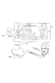
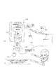
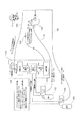
図1〜図3を参照すると、本発明の流体供給システム100は、流体供給源102と、この流体供給源102に接続された流体調節器104とを備えている。本発明は、図3に示すように、複数の流体供給源102及び/又は複数の流体調節器104を備えることができる。流体供給源102には、例えば、酸素発生装置、病院の設定範囲内の据え付けの酸素貯蔵器、又は加圧酸素若しくは液体酸素デュワー瓶の携帯型キャニスタが含まれる。この流体供給システム100は、例えばバッテリあるいは外部電力(図示せず)といった電力供給源と、(全般的に112で示されている)流量センサ、増幅回路及びソフトウェアを含む電子制御装置とを更に含んでいる。図1に示すように、電子制御装置は、隣接する流体供給源102あるいは隣接する出口端部108を含む、流体供給源102と出口端部108との間の任意の位置に配置することができる。加えて、図2〜図3に示すように、電子制御装置は、出口端部と通信するペンダントに配置することができる。
1 to 3, the
流体調節器104は、流体供給源102、並びに出口端部108と流体連通している。そのような流体連通は、例えば、流体調節器を流体供給源及び出口端部に接続しあるいは連結するチューブによって容易にすることができる。流体調節器104は、出口端部108における予め定められた圧力において酸素の流れを中断させる。出口端部108は、図1〜図2に示すような鼻カニューレ、あるいは図3に示すような口鼻カニューレを含むことができる。好ましくは、流体調節器104は、供給源における(例えば、流体供給源内に残る酸素の)入口圧、及び出口端部における出口圧を測定する二つの圧力計を含む。
The
流体調節器104は、流量センサからのデータに基づいて鼻のあるいは口鼻のタブに対する酸素の流れを所定の時間の長さにわたって開放して、出口端部108に酸素のパルスを送るソレノイドバルブを含んでいる。出口端部が、図3に示すように口鼻カニューレを含んでいるときに、流体調節器104はソレノイドバルブであり、(鼻側あるいは口側のうち)いずれの開口が肺に対する明確な流れを「要求しているか」を定める流量センサからのデータに基づいて、所定の長さの時間にわたって口鼻側タブに対する酸素の流れを開放すると共に鼻あるいは口に酸素のパルスを送る。この判定は、一方が鼻側の経路にあり他方が口側の経路にある、流れをモニタするための別々のセンサに基づく。
The
トリガーとして圧力降下を(機械的にあるいは電子的に)検出するのではなく、この発明は、ソレノイドバルブを起動させるために、本質的に瞬間的な鼻側の流れを検出する。酸素供給源の開閉は、ユーザに対して酸素を放出すべく戦略的に配置された、正確に「時間合わせされた」酸素のパルスを供給することができる。この装置は、任意の調節器を「スマートな」節約調節器に本質的に変換させる。この「スマートな」節約調節器鼻あるいは口鼻カニューレシステムには、例えば、ソレノイド、センサ及び電力供給源を自己診断する;不十分な酸素供給源を検出する;カニューレに対する酸素流れの不調、例えば管の分離あるいは管の締め付けを検出する;システムが適切に作動していない場合、連続流れにデフォルト設定する;及び、流量センサあるいは酸素経路の何らかの閉塞を検出するといった、様々な安全の態様をビルトインすることができる。以下により詳しく述べるように、流体調節器104は、弁、例えば圧力バルブ組立体を起動させて、患者の吸息の際に設定された時間、例えば概ね400msにわたって開放させる。
Rather than detecting a pressure drop (mechanically or electronically) as a trigger, the present invention detects an essentially instantaneous nasal flow to activate the solenoid valve. Opening and closing the oxygen source can provide a precisely “timed” pulse of oxygen strategically arranged to release oxygen to the user. This device essentially converts any regulator into a “smart” savings regulator. This “smart” savings regulator nasal or oral nasal cannula system includes, for example, self-diagnosis of solenoids, sensors and power sources; detects insufficient oxygen sources; Built-in various safety aspects, such as detecting segregation or tube tightening; defaulting to continuous flow if the system is not working properly; and detecting any obstruction in the flow sensor or oxygen pathway be able to. As will be described in more detail below, the
図4を参照すると、出口端部108は、そこから延びる2つの鼻カニューレ120及び122を具備する中空体を含むカニューレから構成することができる。鼻カニューレ120、122は、分割チューブ導管126及び導管128により、ソレノイドバルブ104を介して酸素供給源102に接続されている(図1及び図2)鼻側酸素チューブ132に接続される。鼻側流量センサ134は、好ましくは、鼻カニューレ120、122のうちの一つに組み込まれる。代わりに、鼻側流量センサ134は、酸素源に隣接して、あるいはそれらの間のどこかに配置することができる。
Referring to FIG. 4, the
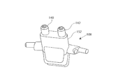
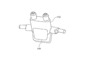
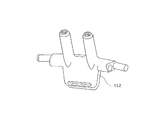
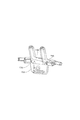
また、図5A〜図5D及び図6を参照すると、出口端部108は、代わりに、そこから延びる2つの鼻カニューレ140、142及び口カニューレ144を具備する中空本体を有する口鼻カニューレを含むことができる。鼻カニューレ140、142は、分割チューブ導管146及び導管148により、ソレノイドバルブ104を介して酸素供給源102に接続されている鼻側酸素チューブ132に接続されている。鼻側流量センサ134は、以下に詳述するように、好ましくは鼻カニューレ140、142のうちの一つに組み込まれる。
Referring also to FIGS. 5A-5D and 6, the
同様のやり方で、口流れカニューレは、流れ通路136、導管138、弁104を介して酸素供給源102に接続される。酸素流量センサ150は、好ましくは流れ通路136に組み込まれる。図5A〜図5Dを再び参照すると、異なる患者に対応するために、口鼻カニューレ108は、様々な長さの人中スペーサ152を含むことができる。更に、口鼻カニューレの鼻カニューレ及び口カニューレは、例えば着脱可能なチューブあるいは長さが調整可能なスリーブを介して、それぞれ接続することができる。
In a similar manner, the mouth flow cannula is connected to the
図7A及び図7Bを参照すると、参照符号1006は、鼻の内部の微小な流れを測定するように設計されたセンサ1006を表しており、マイクロプロセッサあるいはマイクロコントローラ1012を介し、その両方がバッテリ1016から電力が供給されて、起動機構(図7B)と通信する。センサ1006は、好ましくは、例えばスイス、WattwilのInnovative Sensor Technologyにより製造されるMicroflow Sens MFS02センサといった、極めて高速な流量測定部を含んでいる。トリガーアンプと節約調節器との間の様々なあり得る通信のために、例えばシステムは有線、あるいは例えばBluetooth(登録商標)通信機又は他の無線通信機を使用する無線とするができ、それらは呼吸の努力あるいは酸素供給の検出に失敗するリスクを犯すのに十分なだけバッテリが弱まったときにLEDを点灯させる。
Referring to FIGS. 7A and 7B, reference numeral 1006 represents a sensor 1006 designed to measure minute flow inside the nose, both via a microprocessor or
LED1014は、好ましくは、センサがオンでありかつバッテリ1016が充分に充電されていることを報知するために含まれている。マイクロプロセッサ1012は、センサ1006から信号を受信し、送信機1018を介して起動機構(図4B)に信号を送信する。起動機構は、ソレノイドバルブ機構1026に信号を送信するためのマイクロプロセッサあるいはマイクロコントローラ1024と通信する受信器1022を含んでいる。起動機構は、好ましくは、起動機構が起動すると共にバッテリが充分に充電されているときに信号を送信するためのバッテリ1028及びLED1030を含んでいる。
リモートセンサ及び起動機構は、例えばセンサ、起動機構及び酸素供給源を接続するチューブにワイヤを組み込むことにより有線とすることができ、又は、例えばBluetooth(登録商標)短波長無線通信技術若しくは他の無線プロトコルを用いてワイヤレスで通信するように設計することができる。従って、センサと起動機構は、互いに隣接し、あるいは互いに離間することができる。 The remote sensor and activation mechanism can be wired, for example, by incorporating a wire into a tube connecting the sensor, activation mechanism, and oxygen source, or, for example, Bluetooth® short wavelength wireless communication technology or other wireless It can be designed to communicate wirelessly using a protocol. Therefore, the sensor and the activation mechanism can be adjacent to each other or separated from each other.
吸息と呼息との間の動きの特性の違いを測定しあるいは識別するために用いることができる、任意のセンサあるいはセンサの組合せは、節約調節器を同期させかつオン/オフするために用いることができる。患者の吸息/呼息を検出するために用いることができるセンサの実例には、空気流量センサ、空気圧力センサ、吸気と呼気との間の温度差を測定する温度センサ、吸気と呼気との間のガス成分レベルを測定する二酸化炭素ガスセンサ、及び患者の胸部空胴の拡大及び収縮を測定する、例えば歪ゲージ胸ストラップといった身体測定システムが含まれる。例えば特許文献1あるいは特許文献2に記載されている、吸息及び呼息の流れの音を検出する音響センサといった、他のセンサを用いることができる。更に他のあり得るセンサには、例えば特許文献3の教示に従う、患者の吸息により空気の流れが発生するときに変位することができる可動ベーンを有した電気機械式センサが含まれる。 Any sensor or combination of sensors that can be used to measure or identify the difference in motion characteristics between inspiration and expiration can be used to synchronize and turn on / off the savings regulator be able to. Examples of sensors that can be used to detect patient inspiration / expiration include air flow sensors, air pressure sensors, temperature sensors that measure the temperature difference between inspiration and expiration, inspiration and expiration Carbon dioxide gas sensors that measure gas component levels in between, and body measurement systems such as strain gauge chest straps that measure the expansion and contraction of the patient's chest cavity. For example, other sensors such as an acoustic sensor that detects sounds of inhalation and exhalation flows described in Patent Document 1 or Patent Document 2 can be used. Still other possible sensors include electromechanical sensors having movable vanes that can be displaced when air flow is generated by patient inspiration, eg, according to the teachings of US Pat.
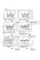
図8A〜図8Fを参照すると、示されているグラフは、本発明のセンサにより評価される様々な条件の下での患者の呼吸サイクルの吸気位相と呼気位相を表すと共に、補助的な酸素供給源からの酸素流れを起動させるべく流れデータがどのように用いられるかを説明している。 Referring to FIGS. 8A-8F, the graphs shown represent the inspiratory and expiratory phases of the patient's respiratory cycle under various conditions evaluated by the sensor of the present invention, and supplemental oxygen delivery. It explains how the flow data is used to activate the oxygen flow from the source.
本発明によるセンサ及び制御装置の回路図が図9に示されている。 A circuit diagram of a sensor and control device according to the present invention is shown in FIG.
いくつかの場合には、二重の起動を回避すべく、患者の生理学的な速度に基づいて流量データの一部を時間切れとすることができる。他のオプションもまた可能である。 In some cases, a portion of the flow data can be timed out based on the patient's physiological rate to avoid double activation. Other options are also possible.
本発明を所定の実施形態を参照して詳細に説明してきたが、説明のためであって限定するためにではなく説明してきた実施形態以外に本発明を実施できることは、当業者が認めるところである。例えば、上記したシステムは、従来の据え付け型の流量調節器あるいは従来の病院の壁ユニット調節器に接続することができて、それらを「スマート調節器」に変換することができる。本システムはまた、CPAPマスクに組み込みあるいは付加的な特徴として適合させることができて、酸素の節約を可能にする。更に他の変更も可能である。従って、添付の請求の範囲の適用範囲は、本明細書に含まれる実施形態の説明に限定されるべきではない。 Although the invention has been described in detail with reference to certain embodiments, those skilled in the art will recognize that the invention can be practiced other than those described for purposes of illustration and not limitation. . For example, the system described above can be connected to a conventional stationary flow regulator or a conventional hospital wall unit regulator, which can be converted to a “smart regulator”. The system can also be incorporated into the CPAP mask or adapted as an additional feature to allow oxygen savings. Still other modifications are possible. Accordingly, the scope of the appended claims should not be limited to the description of the embodiments contained herein.
100 流体供給システム
102 酸素供給源
104 ソレノイドバルブ、流体調節器
108 口鼻カニューレ
120 鼻カニューレ
122 鼻カニューレ
126 分割チューブ導管
128 導管
132 鼻側酸素チューブ
134 鼻側流量センサ
136 通路
138 導管
140 鼻カニューレ
142 鼻カニューレ
144 口カニューレ
146 分割チューブ導管
148 導管
150 酸素流量センサ
152 人中スペーサ
1006 センサ
1012 マイクロコントローラ
1014 LED
1016 バッテリ
1018 送信機
1022 受信器
1024 マイクロコントローラ
1026 ソレノイドバルブ機構
1028 バッテリ
1030 LED
DESCRIPTION OF
1016
Claims (15)
患者の吸息の間に前記少なくとも一つの供給源から流体が流れるように構成された、前記少なくとも一つの流体供給源に接続された少なくとも一つのバルブ組立体;
前記少なくとも一つのバルブ組立体と流体連通する鼻のあるいは口鼻のカニューレを含む出口端部;及び、
患者の吸息に反応して流体供給を起動させる鼻側流量センサ、
を備える流体供給システム。 At least one fluid source;
At least one valve assembly connected to the at least one fluid source configured to allow fluid to flow from the at least one source during patient inhalation;
An outlet end comprising a nasal or oronasal cannula in fluid communication with the at least one valve assembly; and
A nasal flow sensor that activates fluid supply in response to patient inspiration,
A fluid supply system comprising:
前記酸素供給源と鼻カニューレあるいは口鼻カニューレとの間に接続された酸素節約器の制御装置であり、酸素を鼻のあるいは口鼻のカニューレに供給すべく選択的に起動される少なくとも一つの弁を備える制御装置;
鼻側の吸気を検出するように構成されたセンサ;及び、
前記節約器の制御装置を起動させるべく前記センサと通信する起動機構、
を備え、
患者の吸息を検出するための前記センサは、鼻による吸息の間に患者の鼻側の空胴を介した流れを検出し、並びに口による吸息の間に「鼻側の流れ漏れ」を検出するように構成されている装置。 A device for conserving oxygen supplied to a patient from an oxygen source,
At least one valve selectively activated to supply oxygen to the nasal or oronasal cannula, wherein the oxygen conserving device is connected between the oxygen source and the nasal or oral nasal cannula. A control device comprising:
A sensor configured to detect nasal inspiration; and
An activation mechanism in communication with the sensor to activate the controller of the saver;
With
The sensor for detecting patient inspiration detects flow through the patient's nasal cavity during inhalation by the nose, as well as “nasal flow leakage” during inhalation by the mouth. A device configured to detect.
流体供給源及び鼻のあるいは口鼻のカニューレと連通する弁を準備する段階;
前記弁と連通する鼻側流量センサによって、鼻側の吸息の間の、あるいは患者が口で呼吸するときに生じる「鼻側の流れ漏れ」の形態の鼻側の流れを検出する段階;及び、
検出した吸息あるいは漏れに応答して前記弁を起動させ、前記鼻のあるいは口鼻のカニューレを介した患者への供給のために前記流体供給源から流体を放出させる段階、
を含む方法。 A method for conserving a supply of fluid, preferably oxygen, to a patient, comprising:
Providing a valve in communication with a fluid source and a nasal or oral-nose cannula;
Detecting, by means of a nasal flow sensor in communication with said valve, nasal flow during nasal inspiration or in the form of a “nasal flow leak” that occurs when the patient breathes in the mouth; and ,
Activating the valve in response to a detected inspiration or leak and releasing fluid from the fluid source for delivery to the patient via the nasal or nasal cannula;
Including methods.
Applications Claiming Priority (5)
| Application Number | Priority Date | Filing Date | Title |
|---|---|---|---|
| US201361873715P | 2013-09-04 | 2013-09-04 | |
| US61/873,715 | 2013-09-04 | ||
| US201461943610P | 2014-02-24 | 2014-02-24 | |
| US61/943,610 | 2014-02-24 | ||
| PCT/US2014/053924 WO2015034942A1 (en) | 2013-09-04 | 2014-09-03 | Flow triggered pulsed oxygen delivery for medical applications |
Publications (2)
| Publication Number | Publication Date |
|---|---|
| JP2016536081A true JP2016536081A (en) | 2016-11-24 |
| JP2016536081A5 JP2016536081A5 (en) | 2017-05-25 |
Family
ID=52581406
Family Applications (1)
| Application Number | Title | Priority Date | Filing Date |
|---|---|---|---|
| JP2016540352A Pending JP2016536081A (en) | 2013-09-04 | 2014-09-03 | Flow activated pulsed oxygen supply for medical applications |
Country Status (10)
| Country | Link |
|---|---|
| US (1) | US9707366B2 (en) |
| EP (1) | EP3041587A4 (en) |
| JP (1) | JP2016536081A (en) |
| CN (2) | CN111467618A (en) |
| AU (1) | AU2014315301B2 (en) |
| CA (1) | CA2923303A1 (en) |
| MX (1) | MX2016002888A (en) |
| PH (1) | PH12016500423A1 (en) |
| RU (1) | RU2668067C9 (en) |
| WO (1) | WO2015034942A1 (en) |
Cited By (1)
| Publication number | Priority date | Publication date | Assignee | Title |
|---|---|---|---|---|
| WO2018180392A1 (en) * | 2017-03-31 | 2018-10-04 | 帝人ファーマ株式会社 | Respiratory information acquisition device and respiratory information acquisition method |
Families Citing this family (14)
| Publication number | Priority date | Publication date | Assignee | Title |
|---|---|---|---|---|
| US9375542B2 (en) | 2012-11-08 | 2016-06-28 | Covidien Lp | Systems and methods for monitoring, managing, and/or preventing fatigue during ventilation |
| US9907487B2 (en) * | 2015-01-22 | 2018-03-06 | Alexander Gelfand | Non-invasive method and apparatus for determining lung tissue thermal properties and for extra vascular lung water measurement |
| JP6843759B2 (en) | 2015-03-31 | 2021-03-17 | フィッシャー アンド ペイケル ヘルスケア リミテッド | User interface and system for supplying gas to the airways |
| WO2016209129A1 (en) * | 2015-06-25 | 2016-12-29 | Maquet Critical Care Ab | Oxygen boost during mechanical ventilation of a patient |
| GB2567998B (en) | 2016-08-11 | 2022-07-20 | Fisher & Paykel Healthcare Ltd | A collapsible conduit, patient interface and headgear connector |
| CN111065430B (en) * | 2017-08-22 | 2023-03-07 | 皇家飞利浦有限公司 | Breathing mask and mask control method |
| CN110038205A (en) * | 2019-04-12 | 2019-07-23 | 佛山市第一人民医院(中山大学附属佛山医院) | Oral oxygen inhalation device |
| US20210128864A1 (en) * | 2019-11-06 | 2021-05-06 | Koninklijke Philips N.V. | Oxygen recovery during nasal therapy |
| US20210220599A1 (en) | 2020-01-21 | 2021-07-22 | Wearair Ventures, Inc. | Efficient enriched oxygen airflow systems and methods |
| US11247008B1 (en) | 2020-08-05 | 2022-02-15 | Effortless Oxygen, Llc | Flow triggered gas delivery |
| US11420007B2 (en) | 2020-08-05 | 2022-08-23 | Effortless Oxygen, Llc | Flow triggered gas delivery |
| US11318276B2 (en) | 2020-08-05 | 2022-05-03 | Effortless Oxygen, Llc | Flow triggered gas delivery |
| WO2023164365A1 (en) * | 2022-02-22 | 2023-08-31 | Baltimore Respiratory Innovations Inc. | System and method for point-of-delivery patient oxygen supply monitoring |
| WO2023230091A1 (en) * | 2022-05-25 | 2023-11-30 | Carilion Clinic | System, devices and methods for delivering a flow of oxygen |
Citations (2)
| Publication number | Priority date | Publication date | Assignee | Title |
|---|---|---|---|---|
| DE19921917A1 (en) * | 1999-05-12 | 2000-12-14 | Michael Lerch | Control of the amount of enriching oxygen delivered to a user so that enrichment levels are matched to requirements by use of a carbon dioxide sensor, blood oxygen level sensor, etc. and controlling electronics |
| WO2013043504A1 (en) * | 2011-09-20 | 2013-03-28 | Metelits Joel B | Pulsated oxygen delivery for medical applications |
Family Cites Families (28)
| Publication number | Priority date | Publication date | Assignee | Title |
|---|---|---|---|---|
| US3906936A (en) | 1974-02-15 | 1975-09-23 | Mutaz B Habal | Nasal air flow detection method for speech evaluation |
| US4278082A (en) * | 1979-05-11 | 1981-07-14 | Blackmer Richard H | Adjustable nasal cannula |
| US4706664A (en) * | 1986-04-11 | 1987-11-17 | Puritan-Bennett Corporation | Inspiration oxygen saver |
| US5074299A (en) * | 1988-05-02 | 1991-12-24 | Dietz Henry G | Monitor for controlling the flow of gases for breathing during inhalation |
| US5165397A (en) * | 1988-12-15 | 1992-11-24 | Arp Leon J | Method and apparatus for demand oxygen system monitoring and control |
| US5485850A (en) * | 1993-08-13 | 1996-01-23 | Dietz; Henry G. | Monitor of low pressure intervals with control capabilities |
| AU6540299A (en) * | 1995-08-09 | 2000-05-11 | Resmed Limited | Apparatus and methods for oro-nasal respiration monitoring |
| US5694923A (en) | 1996-08-30 | 1997-12-09 | Respironics, Inc. | Pressure control in a blower-based ventilator |
| US5865174A (en) * | 1996-10-29 | 1999-02-02 | The Scott Fetzer Company | Supplemental oxygen delivery apparatus and method |
| US6615831B1 (en) | 1999-07-02 | 2003-09-09 | Respironics, Inc. | Pressure support system and method and a pressure control valve for use in such system and method |
| US6581599B1 (en) * | 1999-11-24 | 2003-06-24 | Sensormedics Corporation | Method and apparatus for delivery of inhaled nitric oxide to spontaneous-breathing and mechanically-ventilated patients |
| US6612307B2 (en) | 2000-09-11 | 2003-09-02 | Western/Scott Fetzer Company | Oxygen conserver |
| US20030140924A1 (en) * | 2001-11-06 | 2003-07-31 | Aylsworth Alonzo C. | Therapeutic gas conserver and control |
| US7614401B2 (en) | 2003-08-06 | 2009-11-10 | Paul S. Thompson | Nasal cannula assembly |
| EP1737520A4 (en) | 2004-04-15 | 2009-10-28 | Resmed Ltd | Snoring treatment apparatus and methods of managing snorers |
| US7222624B2 (en) | 2004-07-02 | 2007-05-29 | Praxair Technology, Inc. | Dual sensor oxygen therapy device |
| US7013898B2 (en) | 2004-07-09 | 2006-03-21 | Praxair Technology, Inc. | Nasal pressure sensor oxygen therapy device |
| US20060169281A1 (en) * | 2005-02-03 | 2006-08-03 | Aylsworth Alonzo C | Continuous flow selective delivery of therapeutic gas |
| US7370651B2 (en) * | 2005-04-01 | 2008-05-13 | Ric Investments, Llc | Gas conserving device |
| US7866320B2 (en) * | 2005-06-08 | 2011-01-11 | Nichols Heath C | Nasal canula and mouthpiece assembly and method |
| US20080078393A1 (en) * | 2005-11-22 | 2008-04-03 | General Electric Company | Respiratory monitoring with cannula receiving respiratory airflows, differential pressure transducer, and ventilator |
| US7422015B2 (en) * | 2005-11-22 | 2008-09-09 | The General Electric Company | Arrangement and method for detecting spontaneous respiratory effort of a patient |
| US8161971B2 (en) * | 2006-08-04 | 2012-04-24 | Ric Investments, Llc | Nasal and oral patient interface |
| NZ742900A (en) * | 2008-06-05 | 2020-02-28 | ResMed Pty Ltd | Treatment of respiratory conditions by automatic control of flow and/or temperature and/or humidity independently to nares via separate flow paths |
| US9044565B2 (en) * | 2008-10-30 | 2015-06-02 | Oridion Medical (1987) Ltd. | Oral-nasal cannula system enabling CO2 and breath flow measurement |
| JP2012508074A (en) | 2008-11-10 | 2012-04-05 | チャート・シークワル・テクノロジーズ・インコーポレイテッド | Medical ventilator system and method using an oxygen concentrator |
| WO2012091967A1 (en) * | 2010-12-31 | 2012-07-05 | O2Ool, Llc | Apparatus for positioning a nasal cannula |
| US20130092165A1 (en) | 2011-09-26 | 2013-04-18 | Anthony David Wondka | Nasal Ventilation Cannula System and Methods |
-
2014
- 2014-09-03 US US14/476,552 patent/US9707366B2/en active Active
- 2014-09-03 WO PCT/US2014/053924 patent/WO2015034942A1/en active Application Filing
- 2014-09-03 CA CA2923303A patent/CA2923303A1/en not_active Abandoned
- 2014-09-03 AU AU2014315301A patent/AU2014315301B2/en not_active Ceased
- 2014-09-03 EP EP14842330.4A patent/EP3041587A4/en not_active Withdrawn
- 2014-09-03 CN CN201911324344.7A patent/CN111467618A/en active Pending
- 2014-09-03 MX MX2016002888A patent/MX2016002888A/en unknown
- 2014-09-03 CN CN201480049058.3A patent/CN105579102A/en active Pending
- 2014-09-03 JP JP2016540352A patent/JP2016536081A/en active Pending
- 2014-09-03 RU RU2016107490A patent/RU2668067C9/en not_active IP Right Cessation
-
2016
- 2016-03-04 PH PH12016500423A patent/PH12016500423A1/en unknown
Patent Citations (2)
| Publication number | Priority date | Publication date | Assignee | Title |
|---|---|---|---|---|
| DE19921917A1 (en) * | 1999-05-12 | 2000-12-14 | Michael Lerch | Control of the amount of enriching oxygen delivered to a user so that enrichment levels are matched to requirements by use of a carbon dioxide sensor, blood oxygen level sensor, etc. and controlling electronics |
| WO2013043504A1 (en) * | 2011-09-20 | 2013-03-28 | Metelits Joel B | Pulsated oxygen delivery for medical applications |
Cited By (7)
| Publication number | Priority date | Publication date | Assignee | Title |
|---|---|---|---|---|
| WO2018180392A1 (en) * | 2017-03-31 | 2018-10-04 | 帝人ファーマ株式会社 | Respiratory information acquisition device and respiratory information acquisition method |
| JPWO2018180392A1 (en) * | 2017-03-31 | 2019-11-07 | 帝人ファーマ株式会社 | Respiratory information acquisition device and respiratory information acquisition method |
| CN110446518A (en) * | 2017-03-31 | 2019-11-12 | 帝人制药株式会社 | Respiration information acquisition device and respiration information adquisitiones |
| KR20190130164A (en) * | 2017-03-31 | 2019-11-21 | 데이진 화-마 가부시키가이샤 | Respiratory information acquisition device and respiration information acquisition method |
| CN110446518B (en) * | 2017-03-31 | 2021-11-05 | 帝人制药株式会社 | Respiratory information acquisition device and respiratory information acquisition method |
| KR102524710B1 (en) | 2017-03-31 | 2023-04-24 | 데이진 화-마 가부시키가이샤 | Respiratory information acquisition device and respiration information acquisition method |
| US11666718B2 (en) | 2017-03-31 | 2023-06-06 | Teijin Pharma Limited | Respiratory information acquisition device and respiratory information acquisition method |
Also Published As
| Publication number | Publication date |
|---|---|
| CN111467618A (en) | 2020-07-31 |
| EP3041587A4 (en) | 2017-05-10 |
| EP3041587A1 (en) | 2016-07-13 |
| AU2014315301A1 (en) | 2016-03-17 |
| AU2014315301B2 (en) | 2017-09-28 |
| RU2668067C2 (en) | 2018-09-25 |
| WO2015034942A1 (en) | 2015-03-12 |
| PH12016500423B1 (en) | 2016-05-16 |
| CA2923303A1 (en) | 2015-03-12 |
| RU2668067C9 (en) | 2019-06-14 |
| RU2016107490A3 (en) | 2018-03-21 |
| US20150059764A1 (en) | 2015-03-05 |
| PH12016500423A1 (en) | 2016-05-16 |
| CN105579102A (en) | 2016-05-11 |
| US9707366B2 (en) | 2017-07-18 |
| MX2016002888A (en) | 2016-11-07 |
| RU2016107490A (en) | 2017-10-09 |
Similar Documents
| Publication | Publication Date | Title |
|---|---|---|
| US9707366B2 (en) | Flow triggered pulsed oxygen delivery for medical applications | |
| US7013898B2 (en) | Nasal pressure sensor oxygen therapy device | |
| EP2121092B1 (en) | Apparatus for delivering a dose of a gaseous drug to a patient | |
| ES2242289T3 (en) | CONTROL DEVICE TO SUPPLY SUPPLEMENTARY OXYGEN FOR BREATHING. | |
| RU2537062C2 (en) | System and respiratory device for supporting positive pressure in patients' respiratory ways | |
| US9987444B2 (en) | System and method for limited flow respiratory therapy | |
| EP2414019A1 (en) | Methods, systems and devices for non-invasive open ventilation with gas delivery nozzles in free space | |
| CN117279685A (en) | System and method for generating and delivering nitric oxide | |
| CN108289784A (en) | Control the equipment and control method of the enrichment of nitric oxide level | |
| US11247008B1 (en) | Flow triggered gas delivery | |
| WO2013043504A1 (en) | Pulsated oxygen delivery for medical applications | |
| US11420007B2 (en) | Flow triggered gas delivery | |
| AU2021221922B2 (en) | Flow triggered gas delivery | |
| US11318276B2 (en) | Flow triggered gas delivery | |
| US20220040426A1 (en) | Flow Triggered Gas Delivery | |
| KR101520857B1 (en) | Portable nebulizer of artificial intelligence spraying type | |
| CN113425959A (en) | Oxygenation and oxygen supply control device and control method thereof |
Legal Events
| Date | Code | Title | Description |
|---|---|---|---|
| A521 | Request for written amendment filed |
Free format text: JAPANESE INTERMEDIATE CODE: A523 Effective date: 20170405 |
|
| A621 | Written request for application examination |
Free format text: JAPANESE INTERMEDIATE CODE: A621 Effective date: 20170405 |
|
| A131 | Notification of reasons for refusal |
Free format text: JAPANESE INTERMEDIATE CODE: A131 Effective date: 20180130 |
|
| A977 | Report on retrieval |
Free format text: JAPANESE INTERMEDIATE CODE: A971007 Effective date: 20180126 |
|
| A521 | Request for written amendment filed |
Free format text: JAPANESE INTERMEDIATE CODE: A523 Effective date: 20180425 |
|
| A02 | Decision of refusal |
Free format text: JAPANESE INTERMEDIATE CODE: A02 Effective date: 20180703 |