CN111467618A - Fluid triggered pulsed oxygen delivery for medical applications - Google Patents
Fluid triggered pulsed oxygen delivery for medical applications Download PDFInfo
- Publication number
- CN111467618A CN111467618A CN201911324344.7A CN201911324344A CN111467618A CN 111467618 A CN111467618 A CN 111467618A CN 201911324344 A CN201911324344 A CN 201911324344A CN 111467618 A CN111467618 A CN 111467618A
- Authority
- CN
- China
- Prior art keywords
- nasal
- fluid
- oxygen
- patient
- sensor
- Prior art date
- Legal status (The legal status is an assumption and is not a legal conclusion. Google has not performed a legal analysis and makes no representation as to the accuracy of the status listed.)
- Pending
Links
Images


Classifications
-
- A—HUMAN NECESSITIES
- A61—MEDICAL OR VETERINARY SCIENCE; HYGIENE
- A61M—DEVICES FOR INTRODUCING MEDIA INTO, OR ONTO, THE BODY; DEVICES FOR TRANSDUCING BODY MEDIA OR FOR TAKING MEDIA FROM THE BODY; DEVICES FOR PRODUCING OR ENDING SLEEP OR STUPOR
- A61M16/00—Devices for influencing the respiratory system of patients by gas treatment, e.g. mouth-to-mouth respiration; Tracheal tubes
- A61M16/06—Respiratory or anaesthetic masks
- A61M16/0666—Nasal cannulas or tubing
- A61M16/0672—Nasal cannula assemblies for oxygen therapy
- A61M16/0677—Gas-saving devices therefor
-
- A—HUMAN NECESSITIES
- A61—MEDICAL OR VETERINARY SCIENCE; HYGIENE
- A61M—DEVICES FOR INTRODUCING MEDIA INTO, OR ONTO, THE BODY; DEVICES FOR TRANSDUCING BODY MEDIA OR FOR TAKING MEDIA FROM THE BODY; DEVICES FOR PRODUCING OR ENDING SLEEP OR STUPOR
- A61M16/00—Devices for influencing the respiratory system of patients by gas treatment, e.g. mouth-to-mouth respiration; Tracheal tubes
- A61M16/021—Devices for influencing the respiratory system of patients by gas treatment, e.g. mouth-to-mouth respiration; Tracheal tubes operated by electrical means
- A61M16/022—Control means therefor
- A61M16/024—Control means therefor including calculation means, e.g. using a processor
-
- A—HUMAN NECESSITIES
- A61—MEDICAL OR VETERINARY SCIENCE; HYGIENE
- A61M—DEVICES FOR INTRODUCING MEDIA INTO, OR ONTO, THE BODY; DEVICES FOR TRANSDUCING BODY MEDIA OR FOR TAKING MEDIA FROM THE BODY; DEVICES FOR PRODUCING OR ENDING SLEEP OR STUPOR
- A61M16/00—Devices for influencing the respiratory system of patients by gas treatment, e.g. mouth-to-mouth respiration; Tracheal tubes
- A61M16/20—Valves specially adapted to medical respiratory devices
- A61M16/201—Controlled valves
- A61M16/202—Controlled valves electrically actuated
-
- A—HUMAN NECESSITIES
- A62—LIFE-SAVING; FIRE-FIGHTING
- A62B—DEVICES, APPARATUS OR METHODS FOR LIFE-SAVING
- A62B7/00—Respiratory apparatus
- A62B7/02—Respiratory apparatus with compressed oxygen or air
-
- A—HUMAN NECESSITIES
- A61—MEDICAL OR VETERINARY SCIENCE; HYGIENE
- A61M—DEVICES FOR INTRODUCING MEDIA INTO, OR ONTO, THE BODY; DEVICES FOR TRANSDUCING BODY MEDIA OR FOR TAKING MEDIA FROM THE BODY; DEVICES FOR PRODUCING OR ENDING SLEEP OR STUPOR
- A61M16/00—Devices for influencing the respiratory system of patients by gas treatment, e.g. mouth-to-mouth respiration; Tracheal tubes
- A61M16/10—Preparation of respiratory gases or vapours
- A61M16/1005—Preparation of respiratory gases or vapours with O2 features or with parameter measurement
- A61M16/101—Preparation of respiratory gases or vapours with O2 features or with parameter measurement using an oxygen concentrator
-
- A—HUMAN NECESSITIES
- A61—MEDICAL OR VETERINARY SCIENCE; HYGIENE
- A61M—DEVICES FOR INTRODUCING MEDIA INTO, OR ONTO, THE BODY; DEVICES FOR TRANSDUCING BODY MEDIA OR FOR TAKING MEDIA FROM THE BODY; DEVICES FOR PRODUCING OR ENDING SLEEP OR STUPOR
- A61M16/00—Devices for influencing the respiratory system of patients by gas treatment, e.g. mouth-to-mouth respiration; Tracheal tubes
- A61M16/0003—Accessories therefor, e.g. sensors, vibrators, negative pressure
- A61M2016/0015—Accessories therefor, e.g. sensors, vibrators, negative pressure inhalation detectors
- A61M2016/0018—Accessories therefor, e.g. sensors, vibrators, negative pressure inhalation detectors electrical
- A61M2016/0021—Accessories therefor, e.g. sensors, vibrators, negative pressure inhalation detectors electrical with a proportional output signal, e.g. from a thermistor
-
- A—HUMAN NECESSITIES
- A61—MEDICAL OR VETERINARY SCIENCE; HYGIENE
- A61M—DEVICES FOR INTRODUCING MEDIA INTO, OR ONTO, THE BODY; DEVICES FOR TRANSDUCING BODY MEDIA OR FOR TAKING MEDIA FROM THE BODY; DEVICES FOR PRODUCING OR ENDING SLEEP OR STUPOR
- A61M16/00—Devices for influencing the respiratory system of patients by gas treatment, e.g. mouth-to-mouth respiration; Tracheal tubes
- A61M16/0003—Accessories therefor, e.g. sensors, vibrators, negative pressure
- A61M2016/0027—Accessories therefor, e.g. sensors, vibrators, negative pressure pressure meter
-
- A—HUMAN NECESSITIES
- A61—MEDICAL OR VETERINARY SCIENCE; HYGIENE
- A61M—DEVICES FOR INTRODUCING MEDIA INTO, OR ONTO, THE BODY; DEVICES FOR TRANSDUCING BODY MEDIA OR FOR TAKING MEDIA FROM THE BODY; DEVICES FOR PRODUCING OR ENDING SLEEP OR STUPOR
- A61M16/00—Devices for influencing the respiratory system of patients by gas treatment, e.g. mouth-to-mouth respiration; Tracheal tubes
- A61M16/0003—Accessories therefor, e.g. sensors, vibrators, negative pressure
- A61M2016/003—Accessories therefor, e.g. sensors, vibrators, negative pressure with a flowmeter
- A61M2016/0033—Accessories therefor, e.g. sensors, vibrators, negative pressure with a flowmeter electrical
- A61M2016/0039—Accessories therefor, e.g. sensors, vibrators, negative pressure with a flowmeter electrical in the inspiratory circuit
-
- A—HUMAN NECESSITIES
- A61—MEDICAL OR VETERINARY SCIENCE; HYGIENE
- A61M—DEVICES FOR INTRODUCING MEDIA INTO, OR ONTO, THE BODY; DEVICES FOR TRANSDUCING BODY MEDIA OR FOR TAKING MEDIA FROM THE BODY; DEVICES FOR PRODUCING OR ENDING SLEEP OR STUPOR
- A61M2205/00—General characteristics of the apparatus
- A61M2205/33—Controlling, regulating or measuring
- A61M2205/3368—Temperature
-
- A—HUMAN NECESSITIES
- A61—MEDICAL OR VETERINARY SCIENCE; HYGIENE
- A61M—DEVICES FOR INTRODUCING MEDIA INTO, OR ONTO, THE BODY; DEVICES FOR TRANSDUCING BODY MEDIA OR FOR TAKING MEDIA FROM THE BODY; DEVICES FOR PRODUCING OR ENDING SLEEP OR STUPOR
- A61M2205/00—General characteristics of the apparatus
- A61M2205/35—Communication
- A61M2205/3546—Range
- A61M2205/3569—Range sublocal, e.g. between console and disposable
-
- A—HUMAN NECESSITIES
- A61—MEDICAL OR VETERINARY SCIENCE; HYGIENE
- A61M—DEVICES FOR INTRODUCING MEDIA INTO, OR ONTO, THE BODY; DEVICES FOR TRANSDUCING BODY MEDIA OR FOR TAKING MEDIA FROM THE BODY; DEVICES FOR PRODUCING OR ENDING SLEEP OR STUPOR
- A61M2205/00—General characteristics of the apparatus
- A61M2205/35—Communication
- A61M2205/3576—Communication with non implanted data transmission devices, e.g. using external transmitter or receiver
- A61M2205/3592—Communication with non implanted data transmission devices, e.g. using external transmitter or receiver using telemetric means, e.g. radio or optical transmission
-
- A—HUMAN NECESSITIES
- A61—MEDICAL OR VETERINARY SCIENCE; HYGIENE
- A61M—DEVICES FOR INTRODUCING MEDIA INTO, OR ONTO, THE BODY; DEVICES FOR TRANSDUCING BODY MEDIA OR FOR TAKING MEDIA FROM THE BODY; DEVICES FOR PRODUCING OR ENDING SLEEP OR STUPOR
- A61M2205/00—General characteristics of the apparatus
- A61M2205/82—Internal energy supply devices
- A61M2205/8206—Internal energy supply devices battery-operated
Abstract
A fluid delivery system provides fluid, such as supplemental oxygen, to a patient in response to inhalation. The fluid delivery system includes a valve assembly that is fluidly activated by sensing a nose. The system includes a sensor configured to detect fluid directly through the nose and to detect any "fluid leaks" through the patient's nasal cavity when inhaled orally. A method for protecting delivery of fluid to a patient and including sensing such nasal fluid is also disclosed.
Description
Technical Field
The present invention relates to devices and methods for monitoring and providing oxygen to a patient, as well as effectively protecting the delivery of oxygen to the patient.
Background
Currently, approximately 100 million patients in the United states receive supplemental oxygen therapy through medical insurance payment systems at a cost of approximately $ 20 billion, with this cost increasing at a rate of approximately 13% per year ("L ong-term oxidative therapy," Up-To-Date; 18 months 1 and 2013 Brian L Tiep, MD Rick Carter, PhD, MBA).
The majority of patients receiving long-term supplemental oxygen therapy (L TOT) have chronic hypoxemia due to chronic obstructive pulmonary disease (COPD.) there is currently no method to cure this disease however the adverse effects of chronic hypoxemia can be alleviated by the administration of long-term oxygen therapy (L TOT.) continuous inhalation of low flow oxygen, typically 2 to 3lpm (L/min), from a nasal cannula increases the oxygen concentration in the patient's breath.
In general, when a patient is diagnosed with chronic hypoxemia, oxygen is prescribed as a fixed flow rate based on a 20 minute titration test in a physician's office, during the test, the patient's blood oxygen saturation is measured by using an invasive blood gas analyzer or a non-invasive device such as a pulse oximeter, while measuring blood saturation (SpO2), the patient may be required to walk on a treadmill in order to measure the need for supplemental oxygen when he or she is exerting his or her effort, based on this simple test, a fixed flow of oxygen is prescribed.
If a patient needs to breathe oxygen even while at rest, he or she will be given a fixed oxygen generating device in his or her home that can be set to produce 93% oxygen, for example, up to 5L/min.
Because oxygen is expensive to provide in small bottles and dewars for mobile use, various oxygen-containing devices (oxygen-containing devices) have been developed to protect oxygen fluids. These prior art oxygen protection devices deliver only a short pulse of oxygen when the patient begins to inhale. By not delivering oxygen during expiration or late inspiration, this will protect oxygen that does not have an effect on increasing the oxygen saturation of the patient. Pneumatic and electronic oxygen protection devices exist today, which both require achieving oxygen protection ratios from 2:1 to 7:1 compared to continuous oxygen fluid delivery. The higher protection ratio can be achieved by electronic means programmed to skip breathing so that the oxygen pulses are delivered only intermittently by breathing. However, electronic devices cannot be used for all ambulatory patients because their higher protection rates can actually lead to poor oxygen saturation of the patient, especially during periods of increased oxygen use and when the patient is walking vigorously or is walking up stairs.
Furthermore, existing protective devices measure the reduction of air pressure in the nasal cavity, which is insufficient for most patients to initiate the release of oxygen in a variety of situations, including: extremely reduced respiratory function; maximum mouth breathing; talking while walking; when walking is fast or speaking is strong; or while sleeping. When these dynamic devices are activated, the patient is "taught" to focus on nasal inhalation to help trigger the device. Often the patient needs to stop his or her activities and focus on his or her nasal breathing, or place a nasal cannula probe in his or her mouth to more effectively trigger the device.
The occurrence of pressure sensing inhalation in electronic oxygen protectors is currently achieved by one of two ways:
1. some prior art designs employ dual lumen cannulas, where one lumen is dedicated to pressure sensing and the other to oxygen delivery. Such designs are meant to be more sensitive to the occurrence of inhalation, but suffer from the disadvantage of being able to deliver oxygen into only one nasal passage.
2. Other designs use a single lumen cannula, which typically has a pressure sensor attached to a T-piece under two nasal prongs (nasalprong). The total pressure drop associated with inhalation is sensed from both nasal passages, and oxygen is then delivered to both nasal passages.
Both designs suffer from the disadvantage that if one nasal passage of the patient becomes blocked, it will interfere with detection and oxygen delivery.
Another drawback of current oxygen generating systems is the fact that the ideal need for oxygen for a patient varies over time, whether short term due To consumption variation or long term due To health improvement or deterioration.when a physician prescribes a patient with a fixed fluid rate of oxygen, physicians are primarily concerned with ensuring that the patient's blood saturation does not fall below 88% To 89% oxygen saturation.A physician does not wish any patient To experience desaturation of less than 90% of oxygen during their activities.although there are high concentrations (above 50%) of oxygen administration for a longer period of time (e.g., absorptive pulmonary atemia, increased oxidative stress and inflammation) with potential theoretical concerns about toxicity, clinical experience in the setting of L TOT provides little support for these concerns "(" L ong-term supplemental oxygen therapy "(" Dato-To-Up, Brick L Tiep, Carter, PhD, MBA).
The current Oxygen therapy program was proven to be error prone by the Fussell et al study (respiratory care. month 2 2003, Vol.48No. 2.) in that study, blood saturation levels of 20 patients with COPD were continuously monitored using pulse oximetry to confirm whether each patient's Oxygen treatment adequately maintained his or her saturation. the conclusion of this study was that there was poor correlation between conventional oxygenation assessment methods and continuous dynamic oximetry during L TOT screening of COPD patients, in a recent article entitled "clinical compositions of the clinical Performance of Oxygen-monitoring Devices" am.J.Respir.Crit. CareMed.2010, month 15; 181 (3510) in the article of 10611071, the collection of all current pressure-sensing-based protective Devices was not claimed to be effective in operation with each of their mouths, but was claimed to be consistent with the results of nasal breathing during the same time as they were expected to be operated by the nasal health Devices.
In many cases, this leads to compliance issues, in which patients may choose not to open the hub and not treat on the physician's prescribed therapy to save on electricity costs, in addition, these oxygen collectors may contribute significant heat to the room, which may further increase energy costs, i.e., for cooling the room.
Of course, pressure-based oxygen protection devices do not meet their requirements when breathing in the mouth during strenuous activity, talking, eating and/or sleeping. Usually patients on dynamic oxygen will have to stop and concentrate on breathing with their nose, or place nasal prongs (prong) in their mouth and suck them to trigger oxygen release. When the oxygen demand is not met, a simple solution is to increase the nasal flow rate, which can lead to the problem of uncomfortable drying of the nasal passages and sometimes increased bleeding of the nasal mucosa. In addition, patients often stop their oxygen delivery system completely while eating.
Disclosure of Invention
It is therefore an object of the present invention to provide a new and improved type of protected oxygen regulator which can be used to effectively and efficiently oxygenate patients and which overcomes the above-mentioned and other drawbacks of the prior art. It is another object of the present invention to provide a new and improved type of protected oxygen regulator which can be used as a stand-alone regulator or as a "piggyback" on-board (or "piggyback") on non-protected regulators to make them effective. Yet another object of the present invention is to provide a new and improved type of protected oxygen regulator that can be integrated into all currently used protected oxygen generators and can be applied to multi-user hospital or clinical liquid oxygen systems to increase efficiency. The present invention may also allow the use of pulsed oxygen during sleep apnea treatment using a C-PAP or Bi-PAP machine.
The following brief summary is not intended to include all features and aspects of the present invention, nor is it intended that the present invention necessarily include all features and aspects discussed in this summary.
The present invention provides an improvement over the prior art devices described above by providing a nasal cannula or a combined nasal and oral cannula with a valve assembly and a flow sensor for sensing "leak flow" through the nasal cavity of a patient. This "hidden signal" mode, combined with simultaneous monitoring of nasal and/or oral flow patterns, enables a true on-demand oxygen delivery system without uncertain or misleading oxygen-both of which result in wasted oxygen, or insufficient oxygen delivered to the patient.
Accordingly, in one embodiment, the present invention provides a fluid delivery system comprising at least one fluid source; at least one valve assembly connected to the at least one fluid source, wherein the at least one valve assembly is configured to allow fluid flow from the at least one fluid source during patient inhalation; an outlet end comprising a nasal or oronasal cannula in fluid communication with at least one valve assembly; and a nasal flow sensor for triggering fluid delivery in response to patient inhalation.
The fluid delivery system also includes a power source configured to operate the at least one valve assembly. The position of the nasal flow sensor may be within or adjacent the nasal cannula or oronasal cannula, or adjacent the source of fluid, or within an air tube between the nasal cannula or oronasal cannula and the at least one source of fluid.
In embodiments where the fluid delivery system comprises an oronasal cannula, the oronasal cannula may comprise a split nasal cannula (split nasal cannula) and an oral cannula. The split nasal cannula and the oral cannula may be coupled to each other and the coupling may be achieved by an adjustable length sleeve or by a detachable tube. Further, the split nasal cannula and the oral cannula are in fluid communication with a common valve assembly or each in fluid communication with a separate valve assembly. The fluid delivery system may also include an oral flow sensor for triggering fluid delivery in response to patient inhalation.
The at least one valve assembly of the fluid delivery system of the present invention may comprise at least one solenoid valve. In addition, the nasal flow sensor may be configured to detect flow through the patient's nasal cavity and detect "nasal flow leakage" when inhaled nasally as well as orally. In a preferred embodiment, the fluid delivered by the fluid delivery system is supplemental oxygen. The fluid delivery system may also include circuitry for controlling at least one valve assembly based on a signal from the flow sensor. The circuit may include a trigger mechanism for initiating the release of fluid through the at least one valve assembly.
In another embodiment, the present invention provides a device for protecting oxygen delivered to a patient from an oxygen supply, comprising: an oxygen protection controller connected between the oxygen supply and the nasal or oronasal cannula, wherein the controller includes at least one valve selectively activated to deliver oxygen to the nasal or oronasal cannula; a sensor configured to sense nasal inhalation; and a trigger mechanism coupled to the sensor for activating the protective controller, wherein the sensor for sensing patient inhalation is configured to detect fluid through the nasal cavity of the patient and detect "nasal flow leakage" during nasal inhalation and oral inhalation.
In yet another embodiment, the sensor of the device is selected from the group consisting of an acoustic sensor, a flow sensor, a pressure sensor, a temperature sensor, a carbon dioxide sensor, a strain gauge, and an electro-mechanical sensor.
Further, the sensor and the trigger mechanism may be remote from each other, and may also communicate via wire or wirelessly.
The present invention also provides a method for protecting (conserved) delivery of a fluid to a patient, comprising the steps of: providing a valve in communication with a fluid source and the nasal or oronasal cannula; sensing nasal flow in the form of "nasal flow leak" occurring during nasal inhalation or when a patient breathes orally with a nasal flow sensor in communication with a valve; and triggering a valve to release fluid from the fluid source for delivery to the patient via the nasal cavity or oronasal cannula in response to the sensed inhalation or leak. The fluid delivered by the method may include oxygen.
Drawings
The invention will be better understood from a reading of the following detailed description taken in conjunction with the drawings in which like reference designators are used to designate like elements, and in which:
FIGS. 1 through 3 are block diagrams of three different systems for fluid delivery according to the present invention;
FIG. 4 is a simplified illustration of a nasal prong and a nasal flow sensor according to the present invention;
FIGS. 5A through 5D are perspective views illustrating an oronasal cannula according to various embodiments of the present invention;
FIG. 6 is an X-ray view of the oronasal cannula of FIG. 5A;
FIGS. 7A and 7B are block diagrams of a remote sensor and trigger mechanism according to a preferred embodiment of the present invention;
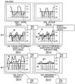
FIGS. 8A through 8F are graphs illustrating sensed oxygen flow according to the present invention; and
FIG. 9 is a block diagram of a sensor and controller for testing a nasal flow sensor and time triggered response according to the present invention.
Detailed Description
Embodiments are described in the following description with reference to the figures, in which like numerals represent the same or similar elements. Reference throughout this specification to "one embodiment," "an embodiment," "some embodiments," or similar language means that a particular feature, structure, or characteristic described in connection with the embodiment is included in at least one embodiment of the present invention. Thus, appearances of the phrases "in one embodiment," "in an embodiment," and similar language throughout this specification may, but do not necessarily, all refer to the same embodiment.
The described features, structures, or characteristics of the invention may be combined in any suitable manner in one or more embodiments. In the following description, numerous specific details are set forth in order to provide a thorough understanding of embodiments of the invention. One skilled in the relevant art will recognize, however, that the invention can be practiced without one or more of the specific details, or with other methods, components, materials, and so forth. In other instances, well-known structures, materials, or operations are not shown or described in detail to avoid obscuring aspects of the invention.
The fluid delivery system of the present invention provides oxygen to the patient at intermittent time intervals based on tidal breathing of the patient. The fluid delivery system includes a nasal or oronasal flow trigger valve assembly that opens in response to inhalation by the patient and closes during the inhalation phase to protect oxygen that would otherwise be wasted filling the "dead space" of the patient prior to the end of inhalation. That is, the present invention senses "flow leakage" through the nasal cavity of a patient upon inhalation by a nasal flow sensor placed within the nasal cannula or along the path of the nasal pull tab (tab) to the regulator and triggers the regulator valve to open and close in synchronization with the patient's tidal breathing.
Nasal flow sensors are sensitive enough to sense "flow leakage" through the nasal passages when the patient breathes in the mouth. With very sensitive flow sensors, a patient whose at least one nostril is not completely blocked has sufficient "flow leakage" through his or her nasal cavity, even when breathing through his or her mouth, to provide a clear definition at the onset of accurate inspiration and expiration. This "hidden signal" alone or in combination with simultaneous monitoring of the flow patterns of the oral and nasal cavities enables a true on-demand oxygen delivery system without uncertain or misleading oxygen, both of which result in wasted oxygen or insufficient oxygen delivered to the patient. With the help of this flow information, the risk relating to, for example, trying to treat sleeping mouth breathers with pulsed oxygen instead of continuous flow is eliminated. Likewise, an ambulatory patient who begins mouth breathing no longer needs to pause and "seize" the breathing rhythm by consciously and deliberately breathing through the nose. Thus, by eliminating any significant delay in oxygen delivery when using this device, the patient has a pleasant sensation of synchronization between the initiation of breathing and the delivery of oxygen, and feels that he or she may walk around and talk spontaneously without fear of missing his or her oxygen pulse. The efficiency of the protective equipment can ultimately be used in hospitalized or bedridden patients from a central liquid supply with a reliable pulsed oxygen delivery system.
Furthermore, unlike the pressure sensors described in the prior art, the sensing and thus the triggering is essentially instantaneous. Thus, there is substantially no delay in delivering supplemental oxygen. There is also no waste of oxygen as compared to conventional flow sensor detectors. Thus, the supplemental oxygen flow is turned on and off in concert with tidal breathing of the patient. Therefore, supplemental oxygen is protected because when the patient does not require oxygen: supplemental oxygen is not provided during "dead space" filling (i.e., the volume of gas inhaled does not account for the volume of gas exchanged) or during exhalation.
As used herein, inhalation is used synonymously with inhalation, and exhalation is used synonymously with exhalation. Inhalation is the movement of air from the external environment through the airway and into the lungs. During inhalation, the chest expands and the diaphragm contracts downward or the back of the body, resulting in expansion of the space within the chest cavity and negative pressure within the chest cavity. This negative pressure causes airflow primarily from the nose or mouth into the pharynx (throat) and trachea, and ultimately into the lungs. However, even when breathing orally, the patient still experiences at least a small amount of airflow through the nose. It has been found that even a small amount of airflow is sufficient to trigger the nasal flow sensor. Further, by using a nasal flow sensor, the determination of inspiration is substantially instantaneous, taking advantage of the most important phase of inspiration to deliver oxygen. While any single (bolus) or pulsed oxygen delivery system is set to flow rate equivalence, there is more consistency and equality between bolus injection and continuous flow rates. The term "pulse equivalent" is assumed to be comparable to continuous flow, how the current protection regulator is set. The continuous flow rate was set at liters per minute.
Because the pulsing devices are not capable of delivering continuous oxygen, they cannot measure in liters per minute. Rather, they are classified by the size of the individual pulses (singles), i.e., the frequency with which the pulses can be delivered in one minute and the time at which the pulses are delivered in the inspiratory (respiratory) cycle. Another problem with the limited pulse oxygen concentrator is when the patient attempts to breathe more than the device is capable of producing per minute. When this happens, the oxygen user will either get a smaller pulse, a pulse with less oxygen, or no pulse at all. In a situation where the oxygen user is exhausted and becomes significantly angry without getting angry down, the device cannot meet the user's needs. Using a nasal flow sensor according to the present invention, an equivalent amount closer to a continuous oxygen flow can be obtained because oxygen is delivered substantially immediately (i.e., typically within a few milliseconds of the beginning of inhalation after the user begins inhaling air). Without the delay inherent in the approach of a pressure sensor triggering oxygen release, it is not necessary to boost the bolus volume to compensate for the delay in delivery.
Also with the nasal flow triggered pulsed oxygen according to the present invention, the user does not have to think about how he or she is breathing-even when the patient is breathing or speaking orally, walking while speaking, or eating, the trigger senses inspiration through the nasal flow sensor. Whether the user has a large nostril or the user is napping or sleeping in a chair. No training is required-the user simply places the cannula within his or her nostril and tests for substantially simultaneous oxygen delivery. Pressure triggered pulsed oxygen delivery has a significant delay in "providing oxygen delivery", while nasal flow triggered oxygen delivery has substantially no significant delay, giving it a more natural feel. It releases oxygen substantially after the user is inhaling, rather than beginning inhalation. By way of comparison, when inhalation is judged using a conventional chest strain gauge, the nasal flow sensor, which currently triggers the solenoid valve to open, occurs before any chest movement is detected! This improved synchronization between inhalation and oxygen delivery is more comfortable, more efficient and more reliable, and also results in better patient compliance because it represents the only performance required of other types of protective devices in practice.
Nasal flow triggered oxygen may also be used with volumetric analysis to determine whether the patient is breathing by mouth or nose. Thus, the present invention can be used to vary oxygen delivery from strict low flow nasal breathing to nasal and oral oxygen delivery when a patient requires a higher flow rate during sleep. This can be achieved with dual oral nasal oxygen cannulas to deliver larger volumes that cannot be pulsed through the nose. With the pressure-triggered pulse delivery that is currently available, high flow oxygen delivery by pulse delivery is not possible.
Other uses of this clinically weak nasal flow during mouth breathing may be useful in the diagnostic field of sleep disorders. Much attention has been directed to sleep studies to confirm sleep apnea diagnosis, which is diagnosed in sleep laboratories and in home sleep studies. Sensing and recording of breathing during sleep can be improved by more accurately measuring inspiratory flow. Thus, the same nasal flow sensor that can trigger pulsed oxygen delivery can also be adapted to effectively measure respiration during diagnostic evaluation. Patients with sleep apnea or periodic breathing and using supplemental oxygen alone may also safely use pulsed oxygen delivery. The device may now allow patients using the C-PAP or Bi-PAP machines to take advantage of the efficiency of pulsed oxygen delivery-delivering oxygen to the nasal passages on inhalation. This is an improvement over the current method of merely adding oxygen to the hose connecting the mask, whereas the current method provides a minimal oxygen delivery system in view of the built-in mask venting, as well as inadvertent mask leaks that occur during the night.
Nasal flow triggered Oxygen delivery can also release patients who are currently traveling at only 3L/min continuous flow rate, using a portable concentrator, it is unreliable to set a pulse of 4-6+ liters per minute during sleep ("critical company of the Clinical compliance of Oxygen-monitoring Devices", am.j.respir.crit.care, 2010, 5/15/2010, 181(10): 1061-1071; published on-line on 2/4/2010, doi: 10.1164/rccm.200910-1638OC PMC id: PMC 2874449.) these pulsed high flow Devices are claimed to be able to oxygenate while the patient is sleeping, but most medical service providers do not consider pulsed high flow Devices to be reliably providing adequate Oxygen to sleeping patients.
Nasal flow triggered oxygen delivery may also accommodate "piggybacking" on-site hospital and clinical center liquid oxygen systems at the point of delivery, providing efficiencies that do not currently exist.
Referring to fig. 1-3, a fluid delivery system 100 of the present invention includes a fluid source 102 and a fluid regulator 104 connected to the fluid source 102. The present invention may include more than one fluid source 102 and/or more than one fluid regulator 104, as shown in fig. 3. Examples of fluid sources 102 include, for example: an oxygen generating device, a fixed oxygen reservoir in a hospital setting, or a portable tank of pressurized oxygen or a liquid oxygen dewar. The fluid delivery system 100 also includes a power source, such as a battery or utility power (not shown), and an electronic control device, generally indicated at 112, including a flow sensor, amplification circuitry and software. As shown in fig. 1, the electronic control device may be located anywhere in fluid source 102 and outlet port 108, including adjacent fluid source 102 or adjacent outlet port 108. Alternatively, as shown in fig. 2-3, the electronic control means may be located in a pendant (pendant) in communication with the outlet port.
The fluid regulator 104 is in fluid communication with the fluid source 102 and the outlet port 108. Such fluid communication may be facilitated by, for example, plumbing connections or coupling fluid regulators to the fluid source and outlet ports. The fluid regulator 104 will discontinue the flow of oxygen at a predetermined pressure at the outlet end 108. Outlet end 108 may comprise a nasal cannula, as shown in fig. 1-2, or an oronasal cannula, as shown in fig. 3. Preferably, the fluid regulator 104 includes a dual pressure gauge for measuring the inlet pressure at the source point (e.g., oxygen left at the fluid source) and the outlet pressure at the outlet end.
The fluid regulator 104 includes a solenoid valve that opens the flow of oxygen into the nasal or oro-nasal pull rings for a predetermined amount of time and sends a pulse of oxygen to the outlet port 108 based on data from the flow sensor. When the outlet port comprises an oronasal cannula, as shown in FIG. 3, the flow regulator 104 is a solenoid valve that opens oxygen flow to the oronasal pull ring for a predetermined amount of time and sends a pulse of oxygen to the mouth or nose based on data from a flow sensor that determines which orifice (nose or mouth) is the "desired" flow to the lungs. This determination is based on separate sensors monitoring flow-one in the nasal and one in the oral passages.
The present invention essentially senses instantaneous nasal flow to trigger the solenoid valve rather than sending a pressure drop as a trigger (whether mechanical or electronic). The switching of the oxygen source may provide precise "timed" pulses of oxygen strategically placed to deliver oxygen to the user. The device can convert virtually any regulator into a "smart" protection regulator. The "intelligent" protective regulator of this nasal or oronasal cannula system may have built in various safety factors such as: self-detecting solenoid valves and sensors and power supplies; detecting an insufficient source of oxygen; detecting a failure of oxygen flow supply to the cannula, for example, if the tube separates or the tube shrinks; continuous flow is not performed, for example, if the system is not working properly; and detect any flow sensor or oxygen channel blockage. As will be described in greater detail below, a valve, e.g., a pressure valve assembly, triggered by the fluid regulator 104 may open upon inhalation by the patient for a set amount of time, e.g., approximately 400 milliseconds.
Referring to fig. 4, the outlet end 108 may comprise a cannula comprising a hollow body having two nasal cannulae 120 and 122 extending therefrom. The nasal cannulae 120, 122 are connected by split tube (split tube) tubing 126 and tubing 128 to a nasal oxygen tube 132 (fig. 1 and 2), the nasal oxygen tube 132 being connected to the oxygen source 102 by the solenoid valve 104. The nasal flow sensor 134 is preferably incorporated into one of the nasal cannulae 120, 122. Alternatively, the nasal flow sensor 134 may be located adjacent the oxygen source, or anywhere in between.
Referring to fig. 5A-5D and 6, the outlet end 108 optionally includes an oral nasal cannula including a hollow body having two nasal cannulae 140 and 142 extending therefrom and an oral cannula 144. The nasal cannulae 140, 142 are connected to a nasal oxygen tube 132 by a split tube conduit 146 and a conduit 148, the nasal oxygen tube 132 being connected to the oxygen source 102 by the solenoid valve 104. A nasal flow sensor 134, described in more detail below, is preferably incorporated into one of the nasal cannulae 140, 142.
In a similar manner, the oral flow cannula is connected to the oxygen supply 102 through the valve 104 via a flow channel 136 and a conduit 138. Oxygen flow sensor 150 is preferably incorporated into flow channel 136. Referring again to fig. 5A-5D, the oronasal cannula 108 may include various lengths of medio-nasal spacers 152 in order to accommodate different patients. Furthermore, the nasal cannula and the oral cannula of the oronasal cannula may be coupled to each other, for example by means of a detachable conduit or a sleeve of adjustable length.
Referring to fig. 7A and 7B, reference numeral 1006 represents a sensor for measuring minimal flow within the nose 1006 and through a microprocessor or microcontroller 1012, both battery driven 1016 and in communication with a trigger mechanism (fig. 7B). the sensor 1006 preferably includes a very fast flow measurement, such as the Microflow SensMFS02 sensor manufactured by wateville, switzerland, innovative sensor technologies, various possible communications between the trigger amplifier and the protective regulator, for example, the system may be a hard wired connection, or it may be used wirelessly, for example, bluetooth communication or other wireless communication device that will turn on the ED L when the battery is weakened to sense breathing or oxygen delivery.
L ED1014 is preferably signaled when the sensor is in operation and the battery 1016 is sufficiently charged, microprocessor 1012 receives the signal from sensor 1006 and sends the signal to the triggering mechanism via transmitter 1018 (FIG. 7B), the triggering mechanism includes a receiver 1022 connected to a microprocessor or microcontroller 1024 for sending a signal to the solenoid mechanism 1026.
The remote sensor and trigger mechanism may be hard-wired, e.g., by inserting a wire into the catheter, connecting the sensor and trigger mechanism and the oxygen source, or may be designed to communicate wirelessly, e.g., using bluetooth short-wave radio transmission technology or other wireless protocols. Thus, the sensor and the trigger mechanism may be adjacent to each other or remote from each other.
Either sensor or combination of sensors may be used to measure or identify property differences between inhalation and exhalation maneuvers that may be used to synchronize and switch protective regulators. Examples of sensors that may be used to detect patient inspiration/expiration include air flow sensors, air pressure sensors, temperature sensors for measuring the temperature difference between inspiration and expiration, carbon dioxide gas sensors for measuring the level of gas composition between inspiration and expiration, and physical measurement systems, such as strain gauge chest straps, capable of measuring the expansion and contraction of the patient's chest. Other sensors, such as acoustic sensors that detect the sounds of inhaled and exhaled flow, are advantageously employed, for example, as described in U.S. published application No. 2005/0183725 or U.S. patent 6,152,130. Another possible sensor includes an electromechanical sensor that incorporates a movable blade that can be displaced when the airflow generated by patient inhalation, for example, in accordance with the teachings of U.S. patent 5,655,523.
Referring to fig. 8A-8F, graphs are shown depicting the inspiratory phase and expiratory phase of a patient's respiratory cycle under various conditions as evaluated by the sensor of the present invention, illustrating how flow data is used to trigger oxygen flow from a supplemental oxygen source.
A circuit diagram of a sensor and control according to the invention is shown in fig. 9.
In some cases, some flow data may be timed to avoid double triggering based on the patient's physiological ratio. Other schemes are also possible.
While the invention has been described in detail with reference to certain embodiments, those skilled in the art will appreciate that the invention can be practiced by other embodiments, which have been presented for purposes of illustration and not of limitation. For example, the system described above can be inserted into a conventional fixed flow regulator, or into a conventional hospital wall regulator and converted to a "smart regulator". The system may also be built in or retrofitted as an additional function of the C-PAP mask and oxygen protection. Accordingly, the scope of the appended claims should not be limited to the embodiments described herein.
Claims (9)
1. A fluid delivery system (100) for controlling delivery of an oxygen-enriched gaseous fluid from a fluid source (102) to a patient, the system comprising:
at least one valve assembly (140) coupled to the at least one fluid source (102), wherein the at least one valve assembly (140) is configured to flow fluid from the at least one fluid source (102);
an outlet end (108) comprising a nasal or oronasal cannula in fluid communication with the at least one valve assembly (104);
a nasal flow sensor for monitoring the patient's breathing and activating the valve assembly (140) in response to patient inhalation; and
a trigger mechanism (112) in communication with the nasal flow sensor (134) to activate a valve for triggering delivery of the fluid to the patient in response to a signal received from the sensor based on inhalation by the patient,
wherein the flow sensor comprises a nasal flow sensor (134), the nasal flow sensor (134) comprising a separate sensor operatively connected via a split nasal cannula (140, 142) and an oral cannula (144) connected to each other and configured to detect a nasal flow leak (1006) through the patient's nasal cavity during snuffing and a nasal flow leak (1008) during sniffing to determine a time of start of inhalation, and to generate a signal based on the time of start of inhalation, and
wherein the nasal flow sensor (134) and the trigger mechanism (112) are remote from each other, and the nasal flow sensor (134) and the trigger mechanism (112) preferably communicate by wire or wirelessly.
2. The fluid delivery system of claim 1, further comprising a power source (1016, 1028) configured to operate the at least one valve assembly.
3. The fluid delivery system of claim 1 or 2, wherein the nasal flow sensor (134) is located in or near the nasal or oronasal cannula (108), or near the at least one fluid source (102), or in an air tube (132) between the nasal or oronasal cannula (108) and the at least one fluid source (102).
4. The fluid delivery system of claim 3, wherein the split nasal cannulae (140, 142) and oral cannula (144) are connected to each other by an adjustable length sleeve (152) or by detachable tubing, or the split nasal cannulae (140, 142) and oral cannula (144) are in fluid communication with a common valve assembly or each with a separate valve assembly.
5. The fluid delivery system of claim 3, further comprising an oral flow sensor (150) for triggering fluid delivery in response to patient inhalation.
6. The fluid delivery system of any one of claims 1 to 5, wherein the at least one valve assembly comprises at least one solenoid valve (140).
7. The fluid delivery system of any one of claims 1 to 6, wherein the delivered fluid comprises supplemental oxygen.
8. The fluid delivery system of any of claims 1 to 7, further comprising circuitry (1012, 1024) for controlling the at least one valve assembly (104) based on a signal from a flow sensor (134).
9. The fluid delivery system of any of claims 1 to 8, wherein the nasal flow sensor (134) is selected from the group consisting of an acoustic sensor, an air flow sensor, a pressure sensor, a temperature sensor, a carbon dioxide sensor, a strain gauge, and an electro-mechanical sensor.
Applications Claiming Priority (5)
| Application Number | Priority Date | Filing Date | Title |
|---|---|---|---|
| US201361873715P | 2013-09-04 | 2013-09-04 | |
| US61/873,715 | 2013-09-04 | ||
| US201461943610P | 2014-02-24 | 2014-02-24 | |
| US61/943,610 | 2014-02-24 | ||
| CN201480049058.3A CN105579102A (en) | 2013-09-04 | 2014-09-03 | Flow triggered pulsed oxygen delivery for medical applications |
Related Parent Applications (1)
| Application Number | Title | Priority Date | Filing Date |
|---|---|---|---|
| CN201480049058.3A Division CN105579102A (en) | 2013-09-04 | 2014-09-03 | Flow triggered pulsed oxygen delivery for medical applications |
Publications (1)
| Publication Number | Publication Date |
|---|---|
| CN111467618A true CN111467618A (en) | 2020-07-31 |
Family
ID=52581406
Family Applications (2)
| Application Number | Title | Priority Date | Filing Date |
|---|---|---|---|
| CN201911324344.7A Pending CN111467618A (en) | 2013-09-04 | 2014-09-03 | Fluid triggered pulsed oxygen delivery for medical applications |
| CN201480049058.3A Pending CN105579102A (en) | 2013-09-04 | 2014-09-03 | Flow triggered pulsed oxygen delivery for medical applications |
Family Applications After (1)
| Application Number | Title | Priority Date | Filing Date |
|---|---|---|---|
| CN201480049058.3A Pending CN105579102A (en) | 2013-09-04 | 2014-09-03 | Flow triggered pulsed oxygen delivery for medical applications |
Country Status (10)
| Country | Link |
|---|---|
| US (1) | US9707366B2 (en) |
| EP (1) | EP3041587A4 (en) |
| JP (1) | JP2016536081A (en) |
| CN (2) | CN111467618A (en) |
| AU (1) | AU2014315301B2 (en) |
| CA (1) | CA2923303A1 (en) |
| MX (1) | MX2016002888A (en) |
| PH (1) | PH12016500423B1 (en) |
| RU (1) | RU2668067C9 (en) |
| WO (1) | WO2015034942A1 (en) |
Families Citing this family (15)
| Publication number | Priority date | Publication date | Assignee | Title |
|---|---|---|---|---|
| US9375542B2 (en) | 2012-11-08 | 2016-06-28 | Covidien Lp | Systems and methods for monitoring, managing, and/or preventing fatigue during ventilation |
| US9907487B2 (en) * | 2015-01-22 | 2018-03-06 | Alexander Gelfand | Non-invasive method and apparatus for determining lung tissue thermal properties and for extra vascular lung water measurement |
| EP3988153B1 (en) * | 2015-03-31 | 2024-04-24 | Fisher & Paykel Healthcare Limited | A user interface for supplying gases to an airway |
| CN107787238B (en) * | 2015-06-25 | 2020-08-07 | 马奎特紧急护理公司 | Oxygenation during mechanical ventilation of a patient |
| CN114569855A (en) | 2016-08-11 | 2022-06-03 | 费雪派克医疗保健有限公司 | Collapsible catheter, patient interface and headgear connector |
| EP3603712B1 (en) * | 2017-03-31 | 2023-11-29 | Teijin Pharma Limited | Respiratory information acquisition device and respiratory information acquisition method |
| CN111065430B (en) * | 2017-08-22 | 2023-03-07 | 皇家飞利浦有限公司 | Breathing mask and mask control method |
| CN110038205A (en) * | 2019-04-12 | 2019-07-23 | 佛山市第一人民医院(中山大学附属佛山医院) | Oral oxygen inhalation device |
| US20210128864A1 (en) * | 2019-11-06 | 2021-05-06 | Koninklijke Philips N.V. | Oxygen recovery during nasal therapy |
| US20210220599A1 (en) | 2020-01-21 | 2021-07-22 | Wearair Ventures, Inc. | Efficient enriched oxygen airflow systems and methods |
| US11420007B2 (en) * | 2020-08-05 | 2022-08-23 | Effortless Oxygen, Llc | Flow triggered gas delivery |
| US11318276B2 (en) | 2020-08-05 | 2022-05-03 | Effortless Oxygen, Llc | Flow triggered gas delivery |
| US11247008B1 (en) | 2020-08-05 | 2022-02-15 | Effortless Oxygen, Llc | Flow triggered gas delivery |
| WO2023164365A1 (en) * | 2022-02-22 | 2023-08-31 | Baltimore Respiratory Innovations Inc. | System and method for point-of-delivery patient oxygen supply monitoring |
| WO2023230091A1 (en) * | 2022-05-25 | 2023-11-30 | Carilion Clinic | System, devices and methods for delivering a flow of oxygen |
Citations (9)
| Publication number | Priority date | Publication date | Assignee | Title |
|---|---|---|---|---|
| US5074299A (en) * | 1988-05-02 | 1991-12-24 | Dietz Henry G | Monitor for controlling the flow of gases for breathing during inhalation |
| AU6540299A (en) * | 1995-08-09 | 2000-05-11 | Resmed Limited | Apparatus and methods for oro-nasal respiration monitoring |
| US20030140924A1 (en) * | 2001-11-06 | 2003-07-31 | Aylsworth Alonzo C. | Therapeutic gas conserver and control |
| US20060169281A1 (en) * | 2005-02-03 | 2006-08-03 | Aylsworth Alonzo C | Continuous flow selective delivery of therapeutic gas |
| US20070113851A1 (en) * | 2005-11-22 | 2007-05-24 | Delisle Matt S | Arrangement and method for detecting respiratory effort of a patient |
| US20080190436A1 (en) * | 2006-08-04 | 2008-08-14 | Jaffe Michael B | Nasal and oral patient interface |
| US20100113955A1 (en) * | 2008-10-30 | 2010-05-06 | Joshua Lewis Colman | Oral-nasal cannula system enabling co2 and breath flow measurement |
| US20110253136A1 (en) * | 2008-06-05 | 2011-10-20 | Resmed Limited | Treatment of respiratory conditions |
| WO2013043504A1 (en) * | 2011-09-20 | 2013-03-28 | Metelits Joel B | Pulsated oxygen delivery for medical applications |
Family Cites Families (21)
| Publication number | Priority date | Publication date | Assignee | Title |
|---|---|---|---|---|
| US3906936A (en) * | 1974-02-15 | 1975-09-23 | Mutaz B Habal | Nasal air flow detection method for speech evaluation |
| US4278082A (en) * | 1979-05-11 | 1981-07-14 | Blackmer Richard H | Adjustable nasal cannula |
| US4706664A (en) * | 1986-04-11 | 1987-11-17 | Puritan-Bennett Corporation | Inspiration oxygen saver |
| US5165397A (en) * | 1988-12-15 | 1992-11-24 | Arp Leon J | Method and apparatus for demand oxygen system monitoring and control |
| US5485850A (en) * | 1993-08-13 | 1996-01-23 | Dietz; Henry G. | Monitor of low pressure intervals with control capabilities |
| US5694923A (en) | 1996-08-30 | 1997-12-09 | Respironics, Inc. | Pressure control in a blower-based ventilator |
| US5865174A (en) * | 1996-10-29 | 1999-02-02 | The Scott Fetzer Company | Supplemental oxygen delivery apparatus and method |
| DE19921917A1 (en) * | 1999-05-12 | 2000-12-14 | Michael Lerch | Control of the amount of enriching oxygen delivered to a user so that enrichment levels are matched to requirements by use of a carbon dioxide sensor, blood oxygen level sensor, etc. and controlling electronics |
| US6615831B1 (en) | 1999-07-02 | 2003-09-09 | Respironics, Inc. | Pressure support system and method and a pressure control valve for use in such system and method |
| US6581599B1 (en) * | 1999-11-24 | 2003-06-24 | Sensormedics Corporation | Method and apparatus for delivery of inhaled nitric oxide to spontaneous-breathing and mechanically-ventilated patients |
| US6612307B2 (en) | 2000-09-11 | 2003-09-02 | Western/Scott Fetzer Company | Oxygen conserver |
| US7614401B2 (en) | 2003-08-06 | 2009-11-10 | Paul S. Thompson | Nasal cannula assembly |
| JP2007532204A (en) | 2004-04-15 | 2007-11-15 | レスメド リミテッド | Snoring treatment device and method for managing snoring |
| US7222624B2 (en) | 2004-07-02 | 2007-05-29 | Praxair Technology, Inc. | Dual sensor oxygen therapy device |
| US7013898B2 (en) | 2004-07-09 | 2006-03-21 | Praxair Technology, Inc. | Nasal pressure sensor oxygen therapy device |
| US7370651B2 (en) * | 2005-04-01 | 2008-05-13 | Ric Investments, Llc | Gas conserving device |
| US7866320B2 (en) * | 2005-06-08 | 2011-01-11 | Nichols Heath C | Nasal canula and mouthpiece assembly and method |
| US20080078393A1 (en) * | 2005-11-22 | 2008-04-03 | General Electric Company | Respiratory monitoring with cannula receiving respiratory airflows, differential pressure transducer, and ventilator |
| JP2012508074A (en) * | 2008-11-10 | 2012-04-05 | チャート・シークワル・テクノロジーズ・インコーポレイテッド | Medical ventilator system and method using an oxygen concentrator |
| WO2012091967A1 (en) * | 2010-12-31 | 2012-07-05 | O2Ool, Llc | Apparatus for positioning a nasal cannula |
| US20130092165A1 (en) * | 2011-09-26 | 2013-04-18 | Anthony David Wondka | Nasal Ventilation Cannula System and Methods |
-
2014
- 2014-09-03 US US14/476,552 patent/US9707366B2/en active Active
- 2014-09-03 WO PCT/US2014/053924 patent/WO2015034942A1/en active Application Filing
- 2014-09-03 RU RU2016107490A patent/RU2668067C9/en not_active IP Right Cessation
- 2014-09-03 JP JP2016540352A patent/JP2016536081A/en active Pending
- 2014-09-03 AU AU2014315301A patent/AU2014315301B2/en not_active Ceased
- 2014-09-03 CN CN201911324344.7A patent/CN111467618A/en active Pending
- 2014-09-03 CA CA2923303A patent/CA2923303A1/en not_active Abandoned
- 2014-09-03 EP EP14842330.4A patent/EP3041587A4/en not_active Withdrawn
- 2014-09-03 CN CN201480049058.3A patent/CN105579102A/en active Pending
- 2014-09-03 MX MX2016002888A patent/MX2016002888A/en unknown
-
2016
- 2016-03-04 PH PH12016500423A patent/PH12016500423B1/en unknown
Patent Citations (10)
| Publication number | Priority date | Publication date | Assignee | Title |
|---|---|---|---|---|
| US5074299A (en) * | 1988-05-02 | 1991-12-24 | Dietz Henry G | Monitor for controlling the flow of gases for breathing during inhalation |
| AU6540299A (en) * | 1995-08-09 | 2000-05-11 | Resmed Limited | Apparatus and methods for oro-nasal respiration monitoring |
| US20030140924A1 (en) * | 2001-11-06 | 2003-07-31 | Aylsworth Alonzo C. | Therapeutic gas conserver and control |
| CN1741830A (en) * | 2002-11-05 | 2006-03-01 | 空气矩阵技术有限公司 | Therapeutic gas conserver and control |
| US20060169281A1 (en) * | 2005-02-03 | 2006-08-03 | Aylsworth Alonzo C | Continuous flow selective delivery of therapeutic gas |
| US20070113851A1 (en) * | 2005-11-22 | 2007-05-24 | Delisle Matt S | Arrangement and method for detecting respiratory effort of a patient |
| US20080190436A1 (en) * | 2006-08-04 | 2008-08-14 | Jaffe Michael B | Nasal and oral patient interface |
| US20110253136A1 (en) * | 2008-06-05 | 2011-10-20 | Resmed Limited | Treatment of respiratory conditions |
| US20100113955A1 (en) * | 2008-10-30 | 2010-05-06 | Joshua Lewis Colman | Oral-nasal cannula system enabling co2 and breath flow measurement |
| WO2013043504A1 (en) * | 2011-09-20 | 2013-03-28 | Metelits Joel B | Pulsated oxygen delivery for medical applications |
Also Published As
| Publication number | Publication date |
|---|---|
| US20150059764A1 (en) | 2015-03-05 |
| AU2014315301A1 (en) | 2016-03-17 |
| MX2016002888A (en) | 2016-11-07 |
| RU2668067C2 (en) | 2018-09-25 |
| EP3041587A4 (en) | 2017-05-10 |
| RU2016107490A3 (en) | 2018-03-21 |
| RU2016107490A (en) | 2017-10-09 |
| EP3041587A1 (en) | 2016-07-13 |
| CN105579102A (en) | 2016-05-11 |
| WO2015034942A1 (en) | 2015-03-12 |
| JP2016536081A (en) | 2016-11-24 |
| AU2014315301B2 (en) | 2017-09-28 |
| PH12016500423A1 (en) | 2016-05-16 |
| CA2923303A1 (en) | 2015-03-12 |
| RU2668067C9 (en) | 2019-06-14 |
| US9707366B2 (en) | 2017-07-18 |
| PH12016500423B1 (en) | 2016-05-16 |
Similar Documents
| Publication | Publication Date | Title |
|---|---|---|
| CN111467618A (en) | Fluid triggered pulsed oxygen delivery for medical applications | |
| US9987444B2 (en) | System and method for limited flow respiratory therapy | |
| US6371114B1 (en) | Control device for supplying supplemental respiratory oxygen | |
| RU2516863C2 (en) | System and respiratory device for supporting patient's airway | |
| WO2008092021A2 (en) | System for providing flow-targeted ventilation synchronized to a patient's breathing cycle | |
| US9895083B2 (en) | Non-invasive ventilation measurement | |
| CN104470571A (en) | System and method for improved compliance in respiratory therapy | |
| CN117279685A (en) | System and method for generating and delivering nitric oxide | |
| CN108289784A (en) | Control the equipment and control method of the enrichment of nitric oxide level | |
| US11247008B1 (en) | Flow triggered gas delivery | |
| US20140326242A1 (en) | Sysems and methods for using partial co2 rebreathing integrated in a ventilator and measurements thereof to determine noninvasive cardiac output | |
| WO2013043504A1 (en) | Pulsated oxygen delivery for medical applications | |
| US11420007B2 (en) | Flow triggered gas delivery | |
| AU2021221922B2 (en) | Flow triggered gas delivery | |
| US11318276B2 (en) | Flow triggered gas delivery | |
| US20220040426A1 (en) | Flow Triggered Gas Delivery | |
| KR101520857B1 (en) | Portable nebulizer of artificial intelligence spraying type |
Legal Events
| Date | Code | Title | Description |
|---|---|---|---|
| PB01 | Publication | ||
| PB01 | Publication | ||
| SE01 | Entry into force of request for substantive examination | ||
| SE01 | Entry into force of request for substantive examination | ||
| WD01 | Invention patent application deemed withdrawn after publication |
Application publication date: 20200731 |
|
| WD01 | Invention patent application deemed withdrawn after publication |