JP2016532905A - Scanning microscope and acousto-optic main beam splitter for the scanning microscope - Google Patents
Scanning microscope and acousto-optic main beam splitter for the scanning microscope Download PDFInfo
- Publication number
- JP2016532905A JP2016532905A JP2016539528A JP2016539528A JP2016532905A JP 2016532905 A JP2016532905 A JP 2016532905A JP 2016539528 A JP2016539528 A JP 2016539528A JP 2016539528 A JP2016539528 A JP 2016539528A JP 2016532905 A JP2016532905 A JP 2016532905A
- Authority
- JP
- Japan
- Prior art keywords
- crystal
- illumination light
- light
- beam splitter
- main beam
- Prior art date
- Legal status (The legal status is an assumption and is not a legal conclusion. Google has not performed a legal analysis and makes no representation as to the accuracy of the status listed.)
- Granted
Links
Images

Classifications
-
- G—PHYSICS
- G02—OPTICS
- G02F—OPTICAL DEVICES OR ARRANGEMENTS FOR THE CONTROL OF LIGHT BY MODIFICATION OF THE OPTICAL PROPERTIES OF THE MEDIA OF THE ELEMENTS INVOLVED THEREIN; NON-LINEAR OPTICS; FREQUENCY-CHANGING OF LIGHT; OPTICAL LOGIC ELEMENTS; OPTICAL ANALOGUE/DIGITAL CONVERTERS
- G02F1/00—Devices or arrangements for the control of the intensity, colour, phase, polarisation or direction of light arriving from an independent light source, e.g. switching, gating or modulating; Non-linear optics
- G02F1/29—Devices or arrangements for the control of the intensity, colour, phase, polarisation or direction of light arriving from an independent light source, e.g. switching, gating or modulating; Non-linear optics for the control of the position or the direction of light beams, i.e. deflection
- G02F1/33—Acousto-optical deflection devices
-
- G—PHYSICS
- G01—MEASURING; TESTING
- G01J—MEASUREMENT OF INTENSITY, VELOCITY, SPECTRAL CONTENT, POLARISATION, PHASE OR PULSE CHARACTERISTICS OF INFRARED, VISIBLE OR ULTRAVIOLET LIGHT; COLORIMETRY; RADIATION PYROMETRY
- G01J3/00—Spectrometry; Spectrophotometry; Monochromators; Measuring colours
- G01J3/12—Generating the spectrum; Monochromators
- G01J3/1256—Generating the spectrum; Monochromators using acousto-optic tunable filter
-
- G—PHYSICS
- G02—OPTICS
- G02B—OPTICAL ELEMENTS, SYSTEMS OR APPARATUS
- G02B21/00—Microscopes
- G02B21/0004—Microscopes specially adapted for specific applications
- G02B21/002—Scanning microscopes
- G02B21/0024—Confocal scanning microscopes (CSOMs) or confocal "macroscopes"; Accessories which are not restricted to use with CSOMs, e.g. sample holders
- G02B21/0032—Optical details of illumination, e.g. light-sources, pinholes, beam splitters, slits, fibers
-
- G—PHYSICS
- G02—OPTICS
- G02B—OPTICAL ELEMENTS, SYSTEMS OR APPARATUS
- G02B21/00—Microscopes
- G02B21/0004—Microscopes specially adapted for specific applications
- G02B21/002—Scanning microscopes
- G02B21/0024—Confocal scanning microscopes (CSOMs) or confocal "macroscopes"; Accessories which are not restricted to use with CSOMs, e.g. sample holders
- G02B21/0052—Optical details of the image generation
- G02B21/0064—Optical details of the image generation multi-spectral or wavelength-selective arrangements, e.g. wavelength fan-out, chromatic profiling
-
- G—PHYSICS
- G02—OPTICS
- G02B—OPTICAL ELEMENTS, SYSTEMS OR APPARATUS
- G02B21/00—Microscopes
- G02B21/0004—Microscopes specially adapted for specific applications
- G02B21/002—Scanning microscopes
- G02B21/0024—Confocal scanning microscopes (CSOMs) or confocal "macroscopes"; Accessories which are not restricted to use with CSOMs, e.g. sample holders
- G02B21/0052—Optical details of the image generation
- G02B21/0068—Optical details of the image generation arrangements using polarisation
-
- G—PHYSICS
- G02—OPTICS
- G02B—OPTICAL ELEMENTS, SYSTEMS OR APPARATUS
- G02B27/00—Optical systems or apparatus not provided for by any of the groups G02B1/00 - G02B26/00, G02B30/00
- G02B27/28—Optical systems or apparatus not provided for by any of the groups G02B1/00 - G02B26/00, G02B30/00 for polarising
- G02B27/283—Optical systems or apparatus not provided for by any of the groups G02B1/00 - G02B26/00, G02B30/00 for polarising used for beam splitting or combining
-
- G—PHYSICS
- G02—OPTICS
- G02F—OPTICAL DEVICES OR ARRANGEMENTS FOR THE CONTROL OF LIGHT BY MODIFICATION OF THE OPTICAL PROPERTIES OF THE MEDIA OF THE ELEMENTS INVOLVED THEREIN; NON-LINEAR OPTICS; FREQUENCY-CHANGING OF LIGHT; OPTICAL LOGIC ELEMENTS; OPTICAL ANALOGUE/DIGITAL CONVERTERS
- G02F1/00—Devices or arrangements for the control of the intensity, colour, phase, polarisation or direction of light arriving from an independent light source, e.g. switching, gating or modulating; Non-linear optics
- G02F1/01—Devices or arrangements for the control of the intensity, colour, phase, polarisation or direction of light arriving from an independent light source, e.g. switching, gating or modulating; Non-linear optics for the control of the intensity, phase, polarisation or colour
- G02F1/11—Devices or arrangements for the control of the intensity, colour, phase, polarisation or direction of light arriving from an independent light source, e.g. switching, gating or modulating; Non-linear optics for the control of the intensity, phase, polarisation or colour based on acousto-optical elements, e.g. using variable diffraction by sound or like mechanical waves
- G02F1/116—Devices or arrangements for the control of the intensity, colour, phase, polarisation or direction of light arriving from an independent light source, e.g. switching, gating or modulating; Non-linear optics for the control of the intensity, phase, polarisation or colour based on acousto-optical elements, e.g. using variable diffraction by sound or like mechanical waves using an optically anisotropic medium, wherein the incident and the diffracted light waves have different polarizations, e.g. acousto-optic tunable filter [AOTF]
Landscapes
- Physics & Mathematics (AREA)
- General Physics & Mathematics (AREA)
- Optics & Photonics (AREA)
- Nonlinear Science (AREA)
- Chemical & Material Sciences (AREA)
- Analytical Chemistry (AREA)
- Spectroscopy & Molecular Physics (AREA)
- Microscoopes, Condenser (AREA)
- Optical Modulation, Optical Deflection, Nonlinear Optics, Optical Demodulation, Optical Logic Elements (AREA)
- Investigating Or Analysing Materials By Optical Means (AREA)
- Investigating, Analyzing Materials By Fluorescence Or Luminescence (AREA)
Abstract
本発明は、走査顕微鏡のための音響光学メインビームスプリッタに関するものであり、この音響光学メインビームスプリッタは、事前に選択された又は事前に選択可能な照明光波長の照明光を、試料を照明するための照明光ビームパスに向け、且つ、試料から到来する検出光を検出光ビームパスに向けるように構成されており、またそのように動作する。この音響光学メインビームスプリッタは以下の特徴を備えている。つまり、音響光学メインビームスプリッタにおいて、照明光波長に対応付けられている音響周波数の1つの力学的な波が伝播されるか、又は、照明光波長に対応付けられており、且つ、同一の音響周波数を有している複数の力学的な波が伝播され、試料から到来する検出光束から、1つの力学的な波との相互作用によって、又は、複数の力学的な波との相互作用によって、検出光束の、第1の直線偏光方向及び照明光波長を有している成分も、検出光束の、第1の直線偏光方向に対して垂直な第2の直線偏光方向及び照明光波長を有している成分も偏向されて、前記検出光束から除去される、及び/又は、1つの力学的な波との相互作用によって、又は、複数の力学的な波との相互作用によって、第1の直線偏光方向及び事前に選択された照明光波長を有している照明光の成分も、第1の直線偏光方向とは異なる、特に第1の直線偏光方向に対して垂直な第2の直線偏光方向及び事前に選択された照明光波長を有している照明光の成分も、試料を照明するための照明光ビームパスへと向けられる。The present invention relates to an acousto-optic main beam splitter for a scanning microscope, which illuminates a sample with illumination light of a pre-selected or pre-selectable illumination light wavelength. For the illumination light beam path and for directing the detection light coming from the sample to the detection light beam path, and operates as such. This acousto-optic main beam splitter has the following features. In other words, in the acousto-optic main beam splitter, one dynamic wave having an acoustic frequency associated with the illumination light wavelength is propagated or associated with the illumination light wavelength and the same acoustic wave is transmitted. A plurality of mechanical waves having a frequency are propagated, and from a detected light beam coming from the sample, by interaction with one mechanical wave, or by interaction with a plurality of mechanical waves, The component having the first linear polarization direction and the illumination light wavelength of the detection light beam also has the second linear polarization direction and the illumination light wavelength perpendicular to the first linear polarization direction of the detection light beam. Component is also deflected and removed from the detection beam and / or by interaction with one dynamic wave or by interaction with a plurality of dynamic waves Polarization direction and pre-selected illumination The component of the illumination light having a light wavelength is also different from the first linear polarization direction, in particular a second linear polarization direction perpendicular to the first linear polarization direction and a preselected illumination light wavelength. A component of the illumination light having a is also directed to the illumination light beam path for illuminating the sample.
Description
本発明は、走査顕微鏡のための音響光学メインビームスプリッタに関するものであり、この音響光学メインビームスプリッタは、事前に選択された又は事前に選択可能な照明光波長の照明光を、試料を照明するための照明光ビームパスに向け、且つ、試料から到来する検出光を検出光ビームパスに向けるように構成されており、またそのように動作する。 The present invention relates to an acousto-optic main beam splitter for a scanning microscope, which illuminates a sample with illumination light of a pre-selected or pre-selectable illumination light wavelength. For the illumination light beam path and for directing the detection light coming from the sample to the detection light beam path, and operates as such.
走査顕微鏡では、試料が光ビームによって照明され、それによって試料から放射される反射光又は蛍光が観測される。照明光ビームの焦点は、制御可能なビーム偏向装置を用いて、一般的に2つのミラーの傾斜させることによって、対象平面において移動される。多くの場合、偏向軸は相互に垂直であり、従って一方のミラーはx方向において偏向され、他方のミラーはy方向において偏向される。ミラーの傾斜は例えばガルバノメータ位置決め素子によって行われる。対象物から到来する光の出力は、走査ビームの位置に依存して測定される。通常の場合、位置決め素子には目下のミラー位置を求めるためのセンサが備えつけられている。 In a scanning microscope, a sample is illuminated by a light beam, whereby reflected light or fluorescence emitted from the sample is observed. The focus of the illumination light beam is moved in the object plane, typically by tilting the two mirrors, using a controllable beam deflector. In many cases, the deflection axes are perpendicular to each other so that one mirror is deflected in the x direction and the other mirror is deflected in the y direction. The mirror is tilted by, for example, a galvanometer positioning element. The light output coming from the object is measured depending on the position of the scanning beam. In a normal case, the positioning element is equipped with a sensor for determining the current mirror position.
特に、共焦点走査顕微鏡では、光ビームの焦点を用いて対象物が3次元で走査される。共焦点走査顕微鏡は、一般的に、光源と、光源の光を絞り(いわゆる励起ピンホール)に焦点合わせする際に用いられるフォーカシング光学系と、ビームスプリッタと、ビームを制御するためのビーム偏向装置と、顕微鏡光学系と、検出絞りと、検出光又は蛍光を検出する検出器と、を有している。照明光は、例えばビームスプリッタを介して入射される。 In particular, in a confocal scanning microscope, an object is scanned in three dimensions using the focus of a light beam. A confocal scanning microscope generally includes a light source, a focusing optical system used to focus light from the light source on a diaphragm (so-called excitation pinhole), a beam splitter, and a beam deflecting device for controlling the beam. And a microscope optical system, a detection aperture, and a detector for detecting detection light or fluorescence. The illumination light is incident through, for example, a beam splitter.
対象物から到来する蛍光は、ビーム偏向装置を介してビームスプリッタへと戻され、更にそのビームスプリッタを通過し、続いて、検出絞りに焦点合わせされる。検出絞りの後段には検出器が設けられている。焦点領域には直接的に由来しない検出光は別の光路を進み、従って検出絞りは通過しないので、その結果、スポット点情報が取得され、このスポット情報は、対象物の連続的な走査によって3次元画像がもたらされる。 Fluorescence coming from the object is returned to the beam splitter via the beam deflecting device, passes further through the beam splitter, and is subsequently focused on the detection aperture. A detector is provided after the detection aperture. Detection light that is not directly derived from the focal region travels in a different optical path, and therefore does not pass through the detection diaphragm. As a result, spot point information is acquired. This spot information is obtained by continuous scanning of the object. A dimensional image is provided.
蛍光顕微鏡では、蛍光だけを検出できるようにするために、試料において反射及び散乱された照明光の成分が検出光から除去されなければならない。このために、従来の顕微鏡では、ダイクロイックフィルタ、いわゆるメインビームスプリッタが使用される。 In a fluorescence microscope, in order to be able to detect only fluorescence, the component of the illumination light reflected and scattered by the sample must be removed from the detection light. For this reason, in a conventional microscope, a dichroic filter, a so-called main beam splitter is used.
その種のビームスプリッタの代わりに、少なくとも1つの光源の励起光を顕微鏡に入射させ、且つ、対象物において散乱及び反射された励起光又は励起波長を、検出ビームパスを介して対象物より到来する光から遮蔽するために、音響光学コンポーネントとして構成されている光学装置を設けることもできる。このことは例えば独国の出願公告明細書、独国特許出願公開第199 06 757号明細書から公知である。この刊行物から公知の光学装置は、非常に簡単な構造での可変の構成を実現するために、スペクトル選択素子によって種々の波長の励起光を遮蔽できることを特徴としている。択一的に、その種の光学装置は、スペクトル選択素子を遮蔽すべき励起波長に合わせて調整できることを特徴としている。 Instead of such a beam splitter, the excitation light of at least one light source is incident on the microscope and the excitation light or excitation wavelength scattered and reflected at the object is light coming from the object via the detection beam path An optical device configured as an acousto-optic component can also be provided for shielding from This is known, for example, from the German published application specification, German Patent Application Publication No. 199 06 757. The optical device known from this publication is characterized in that the excitation light of various wavelengths can be shielded by a spectral selection element in order to realize a variable configuration with a very simple structure. Alternatively, such an optical device is characterized in that the spectral selection element can be adjusted to the excitation wavelength to be shielded.
その種の音響光学コンポーネントの機能は、実質的に、照明光と力学的な波との相互作用を基礎としている。幾つかの音響光学コンポーネントでは、例えばAOTFでは、所望の照明光波長の光に関してブラッグの条件が厳密に満たされているようにするために、力学的な波が厳密に規定された周波数を有していなければならない。ブラッグの条件が満たされていない光は、この音響光学コンポーネントでは、力学的な波によって偏向されない。複数の波長の光が試料を照明するための照明光として使用される場合、異なる周波数を有する複数の力学的な波も同時に形成されなければならない。 The function of such acousto-optic components is essentially based on the interaction of illumination light with dynamic waves. In some acousto-optic components, for example in AOTF, the mechanical wave has a strictly defined frequency to ensure that the Bragg condition is strictly met for light of the desired illumination light wavelength. Must be. Light that does not satisfy the Bragg condition is not deflected by mechanical waves in this acousto-optic component. When light of a plurality of wavelengths is used as illumination light for illuminating the sample, a plurality of dynamic waves having different frequencies must be formed simultaneously.
音響光学コンポーネントは、通常の場合、電気的な変換器(文献においてはトランスデューサと称されることが多い)が取り付けられている、いわゆる音響光学結晶から構成されている。変換器は通常の場合、圧電材料と、その圧電材料の上下に設けられている電極と、を含んでいる。典型的には30MHzから800MHzの間の範囲にある無線周波数を用いて電極を電気的に活性化させることによって、圧電材料が振動され、その結果、音響的な波を、即ち音波を生じさせることができ、この音波は発生後に結晶を通過する。多くの場合、音響的な波は、光学的な相互作用領域を通過した後に、反対側に位置する結晶面において吸収されるか、又は、入射方向とは異なる方向へと反射されるので、光にもはや影響は及ぼされない。 Acousto-optic components usually consist of so-called acousto-optic crystals, to which electrical transducers (often referred to as transducers in the literature) are attached. The transducer usually includes a piezoelectric material and electrodes provided above and below the piezoelectric material. By electrically activating the electrode with a radio frequency typically in the range between 30 MHz and 800 MHz, the piezoelectric material is vibrated, resulting in an acoustic wave, ie a sound wave. This sound wave passes through the crystal after generation. In many cases, the acoustic wave passes through the optical interaction region and is either absorbed by the opposite crystal plane or reflected in a direction different from the incident direction. Is no longer affected.
音響光学結晶は、生じた音波によって結晶の光学特性が変化することを特徴としており、その際、音響によって一種の光学格子又は同等の光学的にアクティブな構造、例えばホログラムが誘導される。結晶を通過した光は光学格子において回折される。相応に、光は種々の回折次数で種々の回折方向へと偏向される。入射する光全体に多かれ少なかれ、波長に依存せずに影響を及ぼす、音響光学コンポーネントが存在する。これについては、例えばAOM(acousto optical modulator)、AOD(acousto optical deflector)、周波数シフタのようなコンポーネントがあることを示唆するにとどめる。 Acousto-optic crystals are characterized in that the optical properties of the crystals are changed by the generated sound waves, in which case a kind of optical grating or an equivalent optically active structure, for example a hologram, is induced by the sound. Light passing through the crystal is diffracted by the optical grating. Correspondingly, the light is deflected in different diffraction directions with different diffraction orders. There are acousto-optic components that affect the incident light more or less independently of wavelength. This only suggests that there are components such as AOM (acousto optical modulator), AOD (acousto optical deflector), and frequency shifter.
更に、例えば放射される無線周波数に依存して個々の波長に選択的に作用するコンポーネント(AOTF)も既に存在している。音響光学素子は、例えば二酸化テルリウムのような複屈折結晶から形成されることが多く、光の入射方向及びその光の偏光に対する結晶軸の姿勢は各素子の光学作用を決定する。これらの関係は、例えば独国特許出願公開第10 2006 053 187号明細書から公知である。 Furthermore, there already exist components (AOTF) that act selectively on individual wavelengths, for example depending on the radio frequency emitted. Acousto-optic elements are often formed from birefringent crystals such as tellurium dioxide, and the incident direction of light and the orientation of the crystal axis with respect to the polarization of the light determine the optical action of each element. These relationships are known, for example, from DE 10 2006 053 187.
メインビームスプリッタとしての音響光学コンポーネントを有している走査顕微鏡の動作様式は、独国特許出願公開第101 37 155号明細書に詳細に記載されている。この刊行物には、接線方向に偏光された照明光を偏向させる第1のAOTFの力学的な波が、接線方向の直線偏光方向を有している照明光波長の成分だけを検出光から完全に除去できることも記載されている。もっとも検出光は、矢状方向の偏光方向を有している成分も、接線方向の偏光方向を有している成分も含んでいる。 The mode of operation of a scanning microscope with an acousto-optic component as main beam splitter is described in detail in DE 101 37 155 A1. In this publication, the mechanical wave of the first AOTF that deflects illuminating light polarized in the tangential direction, the component of the illuminating light wavelength having a tangential linear polarization direction is completely removed from the detected light. It is also described that it can be removed. However, the detection light includes a component having a sagittal polarization direction and a component having a tangential polarization direction.
この理由から、音響光学コンポーネントの後段には、別の音響光学コンポーネントとして形成されている補償素子が設けられている。この別の音響光学コンポーネントもやはりAOTFとして形成されており、別の周波数の別の電磁高周波を用いる別の高周波源によって制御される。別の電磁高周波のHF周波数は、照明光の波長及び矢状方向の偏光方向を有している検出光の成分が遮蔽されるように選択されている。この方式は、検出光から遮蔽すべき、矢状方向の偏光方向を有している光に関して、力学的な波における回折のためのブラッグの条件は、その力学的な波が接線方向の偏光方向を有している光の周波数とは異なる周波数を有している場合にしか満たされないことから必要となる。従って、顕微鏡は、異なる周波数の2つの力学的な波を同時に形成するために、各照明光波長に対して2つの異なるHF周波数を提供しなければならない。更に、別の音波発生器を備えている別の音響光学コンポーネントが必須となる。例えば、4つの波長の照明光を用いて照明が行われるならば、8つの電磁高周波が同時に提供され、それにより、2つの音響光学コンポーネントにおいて分散的に、異なる周波数の8つの力学的な波が形成される場合にのみ、蛍光検出が可能となる。 For this reason, a compensation element formed as another acousto-optic component is provided after the acousto-optic component. This other acousto-optic component is also formed as an AOTF and is controlled by another high frequency source that uses another electromagnetic high frequency at a different frequency. Another electromagnetic high frequency HF frequency is selected such that the component of the detection light having the wavelength of the illumination light and the sagittal polarization direction is shielded. In this method, for light having a sagittal polarization direction to be shielded from detection light, Bragg's condition for diffraction in a dynamic wave is that the dynamic wave is tangentially polarized. It is necessary because it is satisfied only when it has a frequency different from the frequency of the light having the light. Therefore, the microscope must provide two different HF frequencies for each illumination light wavelength in order to form two dynamic waves of different frequencies simultaneously. Furthermore, a separate acousto-optic component with a separate sound wave generator is essential. For example, if illumination is performed using illumination light of four wavelengths, eight electromagnetic high frequencies are provided simultaneously, so that eight mechanical waves of different frequencies are distributed dispersively in the two acousto-optic components. Only when it is formed, fluorescence detection is possible.
従来のダイクロイックメインビームスプリッタを使用しても観測することができない原因不明の妨害的な縞が像に頻繁に発生するということは非常に深刻な問題である。 It is a very serious problem that unfamiliar disturbing fringes that cannot be observed even when a conventional dichroic main beam splitter is used frequently occur in an image.
従って、本発明の課題は、使用時に妨害的な縞が発生しない、音響光学メインビームスプリッタを提供することである。 Accordingly, an object of the present invention is to provide an acousto-optic main beam splitter that does not generate disturbing fringes when in use.
この課題は、以下の特徴を備えている音響光学メインビームスプリッタによって解決される。つまり、音響光学メインビームスプリッタにおいて、照明光波長に対応付けられている音響周波数の1つの力学的な波が伝播されるか、又は、照明光波長に対応付けられており、且つ、同一の音響周波数を有している複数の力学的な波が伝播され、
a.試料から到来する検出光束から、1つの力学的な波との相互作用によって、又は、複数の力学的な波との相互作用によって、検出光束の、第1の直線偏光方向及び照明光波長を有している成分も、検出光束の、第1の直線偏光方向に対して垂直な第2の直線偏光方向及び照明光波長を有している成分も偏向されて、検出光束から除去される、及び/又は、
b.1つの力学的な波との相互作用によって、又は、複数の力学的な波との相互作用によって、第1の直線偏光方向及び事前に選択された照明光波長を有している照明光の成分も、第1の直線偏光方向とは異なる、特に第1の直線偏光方向に対して垂直な第2の直線偏光方向及び事前に選択された照明光波長を有している照明光の成分も、試料を照明するための照明光ビームパスに向けられる。
This problem is solved by an acousto-optic main beam splitter having the following characteristics. In other words, in the acousto-optic main beam splitter, one dynamic wave having an acoustic frequency associated with the illumination light wavelength is propagated or associated with the illumination light wavelength and the same acoustic wave is transmitted. A plurality of dynamic waves with frequencies propagated,
a. From the detected light beam coming from the sample, it has the first linear polarization direction and the illumination light wavelength of the detected light beam by interaction with one dynamic wave or by interaction with multiple dynamic waves. The component having the second linear polarization direction and illumination light wavelength perpendicular to the first linear polarization direction of the detected light beam is also deflected and removed from the detected light beam, and Or
b. A component of illumination light having a first linear polarization direction and a preselected illumination light wavelength by interaction with a single dynamic wave or by interaction with a plurality of dynamic waves Also, a component of the illumination light having a second linear polarization direction different from the first linear polarization direction, in particular perpendicular to the first linear polarization direction, and a preselected illumination light wavelength, Directed to an illumination light beam path for illuminating the sample.
本発明によれば先ず、上述の妨害的な縞は、個々の力学的な波の周波数領域が相互に重畳すると生じる「うなり」に起因しており、これは最終的に、試料及び/又は検出器に到来する光の光出力に周期的な変動をもたらすことが分かった。この問題は、特に、力学的な波がその性質上、無限に狭い音響周波数を、即ち単一の音響周波数を有することができずに、むしろ中心周波数を軸として常に周波数領域が存在しているという事実に基づいている。それにもかかわらず本明細書においては、分かり易くするために音響周波数という用語を用いており、これはその都度、中間周波数を意味している。 According to the invention, first, the disturbing fringes described above are due to “beats” that occur when the frequency regions of the individual dynamic waves overlap each other, which ultimately results in the sample and / or detection. It was found that the optical output of light arriving at the vessel causes periodic fluctuations. The problem is that, in particular, mechanical waves cannot have an infinitely narrow acoustic frequency, that is, a single acoustic frequency due to their nature, but there is always a frequency region around the center frequency. Based on the fact that. Nevertheless, in the present specification, the term acoustic frequency is used for the sake of clarity, and this means an intermediate frequency each time.
本発明によれば、有利には、電磁高周波が印加されることによって音響光学メインビームスプリッタにおいて生じる熱出力が、従来技術から公知の音響光学メインビームスプリッタにおいて生じる熱出力よりも遙に低くなる。つまり、照明波長毎にそれぞれ2つの力学的な波が入射されることによって、非常に大きい熱出力が1つ又は複数の結晶に注入される。このことは、最終的に回折効率を低下させ、ひいては、不可避の温度変動によって偏光方向も変動させ、従って試料及び検出器に到来する光の光出力も変動させる。これら全ての欠点は、本発明による音響光学メインビームスプリッタでは回避されるか、又は少なくとも実質的に低減される。 According to the invention, advantageously, the heat output generated in the acousto-optic main beam splitter by application of electromagnetic high frequency is much lower than the heat output generated in the acousto-optic main beam splitter known from the prior art. In other words, a very large heat output is injected into one or more crystals by the incidence of two dynamic waves for each illumination wavelength. This ultimately lowers the diffraction efficiency, and hence the direction of polarization due to unavoidable temperature fluctuations, and hence the light output of the light arriving at the sample and detector. All these disadvantages are avoided or at least substantially reduced with the acousto-optic main beam splitter according to the invention.
以下では、分かり易くするために先ず、単一の照明光波長の光だけが照明光ビームパスに結合される場合、及び/又は、単一の照明光波長を有している成分だけが、試料から到来する検出光から除去される場合に、本発明による音響光学メインビームスプリッタがどのように機能するかを、特に種々の実施例に基づき説明する。しかしながら下記において更に詳細に説明するように、本発明が基礎とする原理は、複数の照明光波長の照明光が同時に照明光ビームパスに向けられるべき場合、及び/又は、複数の照明光波長の成分が同時に試料から到来する検出光から除去されるべき場合に、それぞれ同一の装置において共通して何度も適用することも可能であり、その際、各照明光波長に対しては、照明光波長に固有のそれぞれ1つの音響周波数の少なくとも1つの固有の力学的な波が必要とされる。 In the following, for the sake of clarity, first, only light of a single illumination light wavelength is coupled into the illumination light beam path and / or only components having a single illumination light wavelength are removed from the sample. How the acousto-optic main beam splitter according to the invention functions when removed from the incoming detection light will be described in particular on the basis of various embodiments. However, as explained in more detail below, the principle on which the present invention is based is that the illumination light of a plurality of illumination light wavelengths should be directed simultaneously into the illumination light beam path and / or the components of the plurality of illumination light wavelengths Are to be removed from the detection light coming from the sample at the same time, it can be applied multiple times in common in the same device, and for each illumination light wavelength, the illumination light wavelength At least one unique dynamic wave of each unique acoustic frequency is required.
本発明による音響光学メインビームスプリッタは更に、1つ又は複数の音響周波数を単純に変更することによって、別の1つ又は複数の波長の光を偏向させることができることから、音響光学メインビームスプリッタが設けられている顕微鏡を非常に個別的に使用することができる、という利点を提供する。 The acoustooptic main beam splitter according to the invention can further deflect light of one or more wavelengths by simply changing one or more acoustic frequencies, so that the acoustooptic main beam splitter is It offers the advantage that the provided microscope can be used very individually.
本発明が基礎とする本質的な着想、即ち、事前に決定された又は事前に決定可能な波長の照明光及び/又は検出光を、その偏光に依存せずに、波長に対応付けられている単一の音響周波数を使用して、照明光ビームパス又は検出光ビームパスに向けるという着想を、種々のやり方で実現することができる。 The essential idea on which the present invention is based, i.e. the illumination and / or detection light of a predetermined or predeterminable wavelength is associated with the wavelength, independent of its polarization. The idea of using a single acoustic frequency to direct the illumination light beam path or the detection light beam path can be realized in various ways.
つまり、例えば、対応付けられた音響周波数の力学的な波が伝播し、且つ、所定の波長の光がその偏光に依存せずに偏向される単一の結晶を使用することができる。しかしながら、音響光学メインビームスプリッタにおいて複数の結晶を、特に2つの結晶を使用することも可能である。以下では、考えられる多数の構成のヴァリエーションの中から例示的に幾つかの構成を説明する。 That is, for example, it is possible to use a single crystal in which a dynamic wave having an associated acoustic frequency propagates and light having a predetermined wavelength is deflected without depending on its polarization. However, it is also possible to use a plurality of crystals, in particular two crystals, in the acousto-optic main beam splitter. In the following, several configurations will be described by way of example from a large number of possible configurations.
特に簡単に実現可能な1つの実施の形態においては、2つの結晶が設けられており、それらの結晶においてはそれぞれ1つの力学的な波が伝播され、その際、力学的な波は同一の音響周波数を有しているが、しかしながら結晶は、その他のパラメータに関して、例えば結晶カット面及び/又は結晶方位及び/又は力学的な波及び光の伝播方向に関して、相互に異なっており、且つ、2つの結晶のうちの第1の結晶においては、第1の直線偏光方向を有している所定の波長の光が偏向され、それに対し、2つの結晶のうちの第2の結晶においては、特に第1の直線偏光方向に対して垂直な第2の直線偏光方向を有している所定の波長の光が偏向されるように、相互に調整されている。 In one embodiment that is particularly easy to implement, two crystals are provided, in which one dynamic wave propagates in each of the crystals, with the dynamic waves being the same acoustic wave. The crystals have frequencies, however, the crystals are different from each other with respect to other parameters, for example with respect to crystal cut planes and / or crystal orientations and / or mechanical wave and light propagation directions, and two In the first crystal of the crystals, light of a predetermined wavelength having the first linear polarization direction is deflected, whereas in the second crystal of the two crystals, the first crystal is particularly the first. Are adjusted so that light of a predetermined wavelength having a second linear polarization direction perpendicular to the linear polarization direction is deflected.
結晶のそのような配置構成を有しているその種の音響光学メインビームスプリッタにおいては、有利には、照明光を照明光ビームパスに入射させるための複数の入光部を設けることができる。特に、有利には、異なる直線偏光方向の照明光が入射され、照明光ビームパスに向けられる。しかしながら、偏光されていない一次光を受光し、少なくとも、1つ又は複数の所定の波長の成分を、必要に応じて1つの結晶の異なる入光部を介して、又は複数の結晶の異なる入光部を介して、試料を照明するための照明光ビームパスに向けることも可能である。その種の音響光学メインビームスプリッタは、例えば、偏光ビームスプリッタを有することができ、この偏光ビームスプリッタは偏光されていない一次光を受光し、また直線偏光方向に依存して空間的に分割することができ、それによって、生じた照明光束には、1つ又は複数の結晶の異なる入光部を介して、1つの力学的な波又は複数の力学的な波を作用させることができる。 In such acousto-optic main beam splitters having such an arrangement of crystals, it is advantageously possible to provide a plurality of light entrances for making the illumination light incident on the illumination light beam path. In particular, advantageously, illumination light of different linear polarization directions is incident and directed to the illumination light beam path. However, it receives unpolarized primary light, and at least one or more components of a predetermined wavelength, if necessary, through different light entrances of one crystal or different light incidences of a plurality of crystals. It is also possible to direct the illumination light beam path for illuminating the sample through the unit. Such an acousto-optic main beam splitter can have, for example, a polarizing beam splitter, which receives the unpolarized primary light and spatially divides it depending on the direction of linear polarization. Thereby, the generated illumination light beam can be subjected to one dynamic wave or a plurality of dynamic waves via different light entrances of one or more crystals.
1つの特別な構成においては、音響光学メインビームスプリッタは、検出光束が連続的に通過するように配置されている、第1の結晶及び第2の結晶を有している。第1の結晶内に存在し、且つ、音響周波数を有している第1の力学的な波との相互作用によって、第1の直線偏光方向及び照明光波長を有している成分が偏向されて、検出光束から除去される。同様に、第2の結晶内に存在し、且つ、音響周波数を有している第2の力学的な波との相互作用によって、第2の直線偏光方向及び照明光波長を有している成分が偏向されて、検出光束から除去される。 In one particular configuration, the acousto-optic main beam splitter has a first crystal and a second crystal that are arranged so that the detected light beam passes continuously. The component having the first linear polarization direction and the illumination light wavelength is deflected by the interaction with the first mechanical wave that exists in the first crystal and has an acoustic frequency. And removed from the detected light flux. Similarly, a component having a second linear polarization direction and an illumination light wavelength by interaction with a second mechanical wave that is present in the second crystal and has an acoustic frequency. Is deflected and removed from the detected light beam.
その種の実施の形態は、複数ある結晶のうちの少なくとも1つの結晶が、例えば調整可能な音響光学フィルタ(acousto optical tunable filter:AOTF)に対して使用されるような、市販の結晶であって良いという極めて重要な利点を有している。その場合有利には、その他の結晶も別のパラメータに関して、第1の結晶の音響周波数と同一の音響周波数を有している力学的な波が、同一の波長を有しているが異なる直線偏光方向を有している光に作用するように形成されている。 Such an embodiment is a commercially available crystal in which at least one of the plurality of crystals is used, for example, for an adjustable optical tunable filter (AOTF). It has the very important advantage of being good. In that case, advantageously, the other waves also have different parameters, with respect to the other parameters, a mechanical wave having the same acoustic frequency as that of the first crystal has the same wavelength but a different linear polarization. It is formed to act on light having a direction.
第1の結晶が市販の結晶であるか、又は特別に製造された結晶であるかに依存せずに、有利には、第1の結晶を形状及び/又はサイズ及び/又は結晶カット面の点に関して第2の結晶と異ならせることができる。択一的又は付加的に、第1の結晶の格子構造に対する検出光束の伝播方向の配向を、第2の結晶の格子構造に対する検出光束の伝播方向の配向とは異ならせることができる、及び/又は、第1の結晶の格子構造に対する第1の力学的な波の伝播方向の配向を、第2の結晶の格子構造に対する第2の力学的な波の伝播方向の配向とは異ならせることができる。 Regardless of whether the first crystal is a commercially available crystal or a specially manufactured crystal, advantageously the first crystal is shaped and / or sized and / or has a crystal cut plane. Can be different from the second crystal. Alternatively or additionally, the orientation of the detection beam in the propagation direction relative to the lattice structure of the first crystal can be different from the orientation of the propagation direction of the detection beam relative to the lattice structure of the second crystal, and / or Alternatively, the orientation of the first mechanical wave propagation direction relative to the lattice structure of the first crystal may be different from the orientation of the second mechanical wave propagation direction relative to the lattice structure of the second crystal. it can.
音響光学メインビームスプリッタが2つの結晶を有している特別な実施の形態においては、有利には、検出光束を先ず第1の結晶を通過させ、続けて第2の結晶を通過させ、また、第1の結晶の力学的な波との相互作用によって、照明光波長の照明光を照明光ビームパスに向けることができる。択一的又は付加的に、検出光束を先ず第1の結晶を通過させ、続けて第2の結晶を通過させ、また、第2の結晶の力学的な波との相互作用によって、照明光波長の照明光を照明光ビームパスに向けることができる。 In a special embodiment in which the acousto-optic main beam splitter has two crystals, it is advantageous to pass the detection beam first through the first crystal and then through the second crystal, The illumination light having the wavelength of the illumination light can be directed to the illumination light beam path by the interaction with the mechanical wave of the first crystal. Alternatively or additionally, the detection beam is first passed through the first crystal, followed by the second crystal, and by the interaction with the mechanical wave of the second crystal, the wavelength of the illumination light Can be directed to the illumination light beam path.
結晶のそのような配置構成を有しているその種の音響光学メインビームスプリッタにおいても、有利には、照明光を照明光ビームパスに入射させるための複数の入光部を設けることができる。特に、有利には、異なる直線偏光方向の照明光が入射され、照明光ビームパスに向けられる。その種の実施の形態においても、偏光されていない一次光を受光し、少なくとも、1つ又は複数の所定の波長の成分を、必要に応じて1つ又は複数の結晶の異なる入光部を介して、試料を照明するための照明光ビームパスに向けることも可能である。特に、その種の音響光学メインビームスプリッタも、例えば、偏光ビームスプリッタを有することができ、この偏光ビームスプリッタは偏光されていない一次光を受光し、また直線偏光方向に依存して空間的に分割することができ、それによって、生じた照明光束には、1つ又は複数の結晶の異なる入光部を介して、1つの力学的な波又は複数の力学的な波を作用させることができる。 Such acousto-optic main beam splitters having such an arrangement of crystals can also advantageously be provided with a plurality of light entrances for allowing illumination light to enter the illumination light beam path. In particular, advantageously, illumination light of different linear polarization directions is incident and directed to the illumination light beam path. Even in such an embodiment, unpolarized primary light is received and at least one or more components of a predetermined wavelength are passed through different light entrances of one or more crystals as required. Thus, it is possible to direct the illumination light beam path for illuminating the sample. In particular, such an acousto-optic main beam splitter can also have, for example, a polarizing beam splitter, which receives the unpolarized primary light and also spatially splits depending on the linear polarization direction. The resulting illumination light flux can then be subjected to one dynamic wave or multiple dynamic waves via different light entrances of one or more crystals.
前述の実施の形態の代替的な実施の形態として、音響光学メインビームスプリッタが、光の事前に選択された波長に対応付けられている音響周波数を有している力学的な波が伝播する結晶を1つだけ有していることも考えられる。 As an alternative to the previous embodiment, an acousto-optic main beam splitter is a crystal through which a mechanical wave propagates having an acoustic frequency associated with a preselected wavelength of light. It is also possible to have only one.
その種の実施の形態は、有利には、結晶及び力学的な波の伝播方向が、以下のように相互に相対的に、また、それぞれが結晶に入射する検出光束に相対的に配向されているように構成されている。つまり、音響光学メインビームスプリッタが、力学的な波によって、検出光束の、第1の直線偏光方向及び照明光波長を有している成分も、検出光束の、第1の直線偏光方向に対して垂直な第2の直線偏光方向及び照明光波長を有している成分も偏向させて、検出光束から除去するように配向されている。 Such an embodiment advantageously has the crystal and mechanical wave propagation directions oriented relative to each other as follows, and relative to the detected light flux each incident on the crystal: It is configured to be. That is, the acousto-optic main beam splitter has a component that has the first linear polarization direction and the illumination light wavelength of the detected light beam due to a mechanical wave. A component having a vertical second linear polarization direction and an illumination light wavelength is also deflected and oriented to be removed from the detected light beam.
特に、結晶内では第1の直線偏光方向の検出光を第1の方向へと偏向させ、それに対して、特に第1の直線偏光方向に対して垂直な第2の直線偏光方向の検出光を別の第2の方向へと偏向させることができる。択一的又は付加的に、第1の直線偏光方向の照明光を、音響光学メインビームスプリッタの第1の入光部へと入射させ、それに対して、第2の直線偏光方向の光を、音響光学メインビームスプリッタの第2の入光部へと入射させることも可能である。 In particular, in the crystal, the detection light in the first linear polarization direction is deflected in the first direction, and the detection light in the second linear polarization direction perpendicular to the first linear polarization direction in particular is detected. It can be deflected in another second direction. Alternatively or additionally, the illumination light in the first linear polarization direction is incident on the first light incident portion of the acousto-optic main beam splitter, while the light in the second linear polarization direction is It is also possible to enter the second light incident portion of the acousto-optic main beam splitter.
音響光学ビームスプリッタの特別な実施の形態に依存せずに、しかしながら、特に力学的な波が1つの照明光波長及び2つの直線偏光方向を有している光成分に作用する音響光学ビームスプリッタにおいては、有利には、メインビームスプリッタのビームガイドコンポーネントは、検出光束の残存部分が音響光学メインビームスプリッタから共線的に出射される、及び/又は、所望の波長の全ての照明光束は、その偏光方向に依存せずに、その照明光束が向けられた照明光ビームパスにおいて共線的に統合される。 Without depending on the particular embodiment of the acousto-optic beam splitter, however, in an acousto-optic beam splitter in which, in particular, a mechanical wave acts on a light component having one illumination light wavelength and two linear polarization directions Advantageously, the beam guide component of the main beam splitter allows the remaining part of the detected beam to be emitted collinearly from the acousto-optic main beam splitter and / or all the illumination beam of the desired wavelength Regardless of the polarization direction, the illumination beam is integrated collinearly in the directed illumination light beam path.
その種の音響光学メインビームスプリッタの具体的な構造、特に1つ又は複数の力学的な波の伝播方向及び検出光束の伝播方向に相対的な結晶の配向、並びに、1つ又は複数の力学的な波及び検出光束の相互に相対的な配向、また、入射面及び出射面の相互的な配向及び結晶の光学軸に対する入射面及び出射面の配向を、特に分割された照明光が音響光学メインビームスプリッタ及び/又は結晶から共線的な照明光束として出射される構成に関して、例えば、下記において説明する反復的な方法に従い発展させることができ、この方法は有利には、実際の構成部材に基づいてではなく、コンピュータシミュレーションにおいて実行され、これは結晶形状、面及び結晶格子の配向の個々のパラメータ、力学的な波の伝播方向の配向、及び、検出光及び/又は照明光の伝播方向が所望の要求に応じるまで行われる。もっとも、この方法は実際の構成部材に基づいても実現することは可能であると考えられる。コンピュータシミュレーションにおいて関連する全てのパラメータがこのようにして求められると、続けて、結晶が別のステップにおいて製造される。 The specific structure of such an acousto-optic main beam splitter, in particular the orientation of the crystal relative to the direction of propagation of one or more mechanical waves and the direction of propagation of the detected light beam, and one or more mechanical The relative illumination orientation of the light wave and the detection light beam, the mutual orientation of the entrance surface and the exit surface, and the orientation of the entrance surface and the exit surface with respect to the optical axis of the crystal. With regard to the arrangement emitted as a collinear illumination beam from the beam splitter and / or crystal, it can be developed, for example, according to the iterative method described below, which method is advantageously based on the actual component Rather than computer simulation, which involves individual parameters of crystal shape, plane and crystal lattice orientation, mechanical wave propagation direction orientation, and detection And / or propagation direction of the illumination light is performed until meet the desired requirements. However, it is considered that this method can be realized based on actual components. Once all relevant parameters in the computer simulation have been determined in this way, crystals are subsequently produced in a separate step.
先ず、公知の通常の結晶カット面及び公知の配向を有している音響光学構成部材が、例えば市販のAOTFが、90°の入射角で検出光束を結晶の入射面へと入射させるように、顕微鏡のビームパスに導入される。続いて、結晶は有利には、入射する検出光束及び力学的な波の伝播方向によって張られている平面において、1つ又は複数の力学的な波を有している検出光束から、1つ又は複数の照明光波長の2つの直線偏光成分が偏向されて、検出光束から除去されるまで、十分に回転され、従って、力学的な波の伝播方向と結晶軸との間の角度も変更される。 First, an acousto-optic component having a known normal crystal cut surface and a known orientation is used so that, for example, a commercially available AOTF causes the detection light beam to be incident on the incident surface of the crystal at an incident angle of 90 °. Introduced into the beam path of the microscope. Subsequently, the crystal is advantageously one or more from the detection beam having one or more dynamic waves in a plane stretched by the incident detection beam and the direction of propagation of the dynamic wave. The two linearly polarized components of the multiple illumination light wavelengths are deflected and rotated sufficiently until they are removed from the detected light beam, thus changing the angle between the dynamic wave propagation direction and the crystal axis. .
もっとも、通常の場合、回転によって、放出された検出光の共線性が失われることにある。この理由から、後続の反復ステップにおいては、結晶を回転させることなく、入射面が入射する検出光束に対して再び垂直になるように、結晶の形状が変更される。更なるステップにおいては、結晶を回転させるのではなく、結晶の形状を変更することによって、検出光が共線的な検出光束として結晶から出射されるように、検出光のための出射面が配向される。 However, in a normal case, the collinearity of the emitted detection light is lost due to rotation. For this reason, in subsequent iteration steps, the crystal shape is changed so that the incident surface is again perpendicular to the incident detection beam without rotating the crystal. In a further step, the exit surface for the detection light is oriented so that the detection light is emitted from the crystal as a collinear detection beam by changing the shape of the crystal rather than rotating the crystal. Is done.
もっとも、結晶の形状を変更することによって、通常の場合、力学的な波によって、1つ又は複数の照明光波長の2つの各直線偏光成分はもはや偏向されずに検出光束から除去されることになる。このことから、結晶はこの条件が再び満たされるまで、再び回転される。続いて、既に説明した別の反復ステップが繰り返される。 However, by changing the shape of the crystal, the two linearly polarized components of one or more illumination light wavelengths are no longer deflected and removed from the detected light beam, usually by mechanical waves. Become. From this, the crystal is rotated again until this condition is met again. Subsequently, another iteration step already described is repeated.
2つの直線偏光成分が同時に偏向する条件と、共線的な光の出射の条件とが満たされるまで、反復サイクルが複数回実行される。通常の場合、本方法は非常に高速に収束されるので、小数の反復サイクルが実行された後には目的が達成されている。 The iterative cycle is executed a plurality of times until the condition that the two linearly polarized light components are simultaneously deflected and the condition of collinear light emission are satisfied. In the usual case, the method converges so quickly that the objective is achieved after a small number of iterative cycles have been performed.
1つの特別な実施の形態においては、結晶の回転時に、検出光の直線偏光方向に関して、照明光波長を有している全ての一次回折光が共線的に結晶から出射されることがその都度顧慮される。その種の実施の形態は、その都度ただ1つの力学的な波が、異なる直線偏光のそれぞれ2つの成分を検出光束から除去できるという利点だけではなく、更には、上述の共線性が生じる一次回折の光路を介して、多色の照明光を共線的に照明光ビームパスに回折させることができるという利点も提供する。 In one particular embodiment, every time the crystal rotates, all first-order diffracted light having the illumination light wavelength is collinearly emitted from the crystal with respect to the linear polarization direction of the detection light. Be considered. Such an embodiment not only has the advantage that only one dynamic wave in each case can remove each two components of different linearly polarized light from the detection beam, but also the first order diffraction that produces the collinearity described above. This also provides the advantage that multicolor illumination light can be collinearly diffracted into the illumination light beam path via the optical path.
更に上記において説明したように、音響光学メインビームスプリッタが、光の事前に選択された複数の波長のうちの1つに対応付けられている音響周波数を有しており、且つ、事前に選択された波長の光にその偏光に依存せずに作用する力学的な波が伝播する結晶を1つだけ有していることも可能である。 Further, as explained above, the acousto-optic main beam splitter has an acoustic frequency associated with one of a plurality of pre-selected wavelengths of light and is pre-selected. It is also possible to have only one crystal in which a dynamic wave acting on light of a different wavelength does not depend on its polarization.
本発明による音響光学メインビームスプリッタの1つの特別な実施の形態においては、その種の2つの結晶が相前後して設けられており、それによって、それら2つの結晶を検出すべき検出光が連続的に通過する。その種の実施の形態は、試料から到来する検出光からの、1つ又は複数の照明光波長を有している光成分の除去に関して非常に良好な効率を提供する。更には、その種の実施の形態は有利には、別の照明光束を顕微鏡の照明光ビームパスへと入射させるための付加的な入射の可能性を提供する。特に、複数の結晶を備えているその種の実施の形態は、複数の照明光束を顕微鏡の照明光ビームパスへと同時に入射させることができる。 In one particular embodiment of the acousto-optic main beam splitter according to the invention, two such crystals are provided one after the other so that the detection light for detecting the two crystals is continuous. Pass through. Such an embodiment provides very good efficiency with respect to the removal of light components having one or more illumination light wavelengths from detection light coming from the sample. Furthermore, such an embodiment advantageously provides an additional incidence possibility for allowing another illumination beam to be incident on the illumination light beam path of the microscope. In particular, such an embodiment comprising a plurality of crystals allows a plurality of illumination beams to be simultaneously incident on the illumination light beam path of the microscope.
特に、その種の配置構成の第1の結晶においても、第2の結晶においても、所定の波長の光をその偏光に依存せずに偏向させる力学的な波がそれぞれ1つずつ伝播されるが、その際、結晶内を伝播する力学的な波の音響周波数は異なっていても良い。むしろ、相前後して設けられている音響光学コンポーネントの構造を、特に、結晶の構造及び配向を、音響周波数を有している、第1の結晶内を伝播する力学的な波も、音響周波数を有している、第2の結晶内を伝播する力学的な波も、それぞれ偏光に依存せずに、照明光波長の光に作用するように異ならせることも可能である。 In particular, in each of the first crystal and the second crystal having such an arrangement, one mechanical wave is transmitted that deflects light of a predetermined wavelength without depending on the polarization. In that case, the acoustic frequency of the dynamic wave propagating in the crystal may be different. Rather, the mechanical wave propagating in the first crystal, which has an acoustic frequency, especially the structure and orientation of the acousto-optic component provided in series, the crystal structure and orientation, is also the acoustic frequency. The dynamic wave propagating in the second crystal having the above can also be made different so as to act on the light of the illumination light wavelength without depending on the polarization.
既に説明したように、有利には、検出光束の残存部分が音響光学メインビームスプリッタから共線的に出射されるように、メインビームスプリッタのビームガイドコンポーネントを配置及び構成することができる。 As already explained, the beam guide component of the main beam splitter can advantageously be arranged and configured in such a way that the remaining part of the detection beam is emitted collinearly from the acousto-optic main beam splitter.
音響光学メインビームスプリッタは、有利には、第1の直線偏光方向が、結晶の複屈折特性に関する通常光の直線偏光方向であるように構成されている。択一的又は付加的に、第2の直線偏光方向を、結晶の複屈折特性に関する通常光の直線偏光方向とすることができる、及び/又は、第1の直線偏光方向又は第2の直線偏光方向を、力学的な波の伝播方向及び検出光束の伝播方向によって張られている平面内に配置することができる。 The acousto-optic main beam splitter is advantageously configured such that the first linear polarization direction is the linear polarization direction of normal light with respect to the birefringence characteristics of the crystal. Alternatively or additionally, the second linear polarization direction can be the normal light linear polarization direction with respect to the birefringence characteristics of the crystal and / or the first linear polarization direction or the second linear polarization direction. The direction can be arranged in a plane that is stretched by the propagation direction of the dynamic wave and the propagation direction of the detected light beam.
本発明によれば有利には、音響光学メインビームスプリッタが、試料を照明するための、特に複数の異なる照明光束を顕微鏡の照明光ビームパスに向けるための多数の可能性を提供するように構成されている。特に有利には、音響光学メインビームスプリッタが複数の一次光束を入射させるための複数の入光部を有しており、それらの入光部からそれぞれ、事前に設定された又は事前に設定可能な1つの波長の照明光、又は、事前に設定された又は事前に設定可能な複数の波長の照明光を分割することができ、且つ、照明光ビームパスに向けることができる。 According to the invention, the acousto-optic main beam splitter is advantageously configured to provide a number of possibilities for illuminating the sample, in particular for directing a plurality of different illumination beams into the illumination light beam path of the microscope. ing. Particularly advantageously, the acousto-optic main beam splitter has a plurality of light entrances for the incidence of a plurality of primary light beams, each of which is preset or preset in advance. One wavelength of illumination light or multiple wavelengths of preset or preset wavelength illumination light can be split and directed into the illumination light beam path.
例えば、1つの特別な実施の形態においては、音響光学メインビームスプリッタが第1の結晶及び第2の結晶を有しており、それらの結晶は特に、検出光束が連続的に通過するように配置されており、その際、第1の結晶内に存在し、且つ、音響周波数を有している第1の力学的な波との相互作用によって、第1の直線偏光方向及び照明光波長を有している照明光が試料を照明するために照明光ビームパスに向けられ、また、第2の結晶内に存在し、且つ、音響周波数を有している第2の力学的な波との相互作用によって、第1の直線偏光方向とは異なる第2の直線偏光方向及び照明光波長を有している照明光が試料を照明するための照明光ビームパスに向けられる。 For example, in one special embodiment, the acousto-optic main beam splitter has a first crystal and a second crystal, which are particularly arranged so that the detected light beam passes continuously. In this case, the first linear polarization direction and the illumination light wavelength are obtained by the interaction with the first dynamic wave that exists in the first crystal and has an acoustic frequency. Interacting with a second mechanical wave that is directed into the illumination light beam path to illuminate the sample and is present in the second crystal and has an acoustic frequency Thus, the illumination light having the second linear polarization direction and the illumination light wavelength different from the first linear polarization direction is directed to the illumination light beam path for illuminating the sample.
択一的に、結晶内を伝播する力学的な波との相互作用によって、第1の多色の、有利には共線的な、第1の直線偏光方向を有している一次光束からも、第2の多色の、有利には共線的な、第1の直線偏光方向とは異なる、特に、第1の直線偏光方向に対して垂直な第2の直線偏光方向を有している一次光束からも、それぞれ、力学的な波の周波数に対応付けられている照明光波長の照明光を分割し、試料を照明するために照明光ビームパスに向けるように音響光学メインビームスプリッタを構成することができるか、又は、結晶内を伝播する力学的な波との相互作用によって、第1の直線偏光方向及び照明光波長を有している照明光も、特に第1の直線偏光方向に対して垂直な別の第2の直線偏光方向及び照明光波長を有している照明光も、試料を照明するための照明光ビームパスに向けるように音響光学メインビームスプリッタを構成することができる。 Alternatively, from the first multi-colored, preferably collinear, primary light beam having the first linear polarization direction by interaction with mechanical waves propagating in the crystal. The second multicolor, preferably collinear, has a second linear polarization direction that is different from the first linear polarization direction, in particular perpendicular to the first linear polarization direction. The acousto-optic main beam splitter is configured to divide the illumination light of the illumination light wavelength corresponding to the frequency of the dynamic wave from the primary light beam and direct it to the illumination light beam path to illuminate the sample. Illumination light having a first linear polarization direction and an illumination light wavelength can also be produced, particularly with respect to the first linear polarization direction, by interaction with mechanical waves propagating in the crystal. Illumination light having another second linear polarization direction and illumination light wavelength perpendicular to each other, It is possible to configure the acousto-optic main beam splitter to direct the illumination light beam path for illuminating a fee.
本発明によるメインビームスプリッタを用いることによって、波長及び/又は偏光に関して相互に異ならせることができる種々の照明光成分を、試料を照明するための照明光ビームパスに向け、例えば分解能を高める特別な効果を惹起させることができる。特に、本発明によるメインビームスプリッタは、STED(Stimulated Emission Depletion)顕微鏡の分野において、又は、CARS(Coherent Anti Stokes Raman Spectroscopy)顕微鏡の分野において、又は、SRS(Stimulated Raman Scattering)顕微鏡の分野において、又は、CSRS(Coherent Stokes Raman Scattering)顕微鏡の分野において、又は、Rikes(Raman induced Kerr−Effect Scattering)顕微鏡の分野において、有利に使用することができる。 By using the main beam splitter according to the invention, the special effect of increasing the various illumination light components, which can be different from each other in terms of wavelength and / or polarization, to the illumination light beam path for illuminating the sample, for example increasing the resolution Can be triggered. In particular, the main beam splitter according to the present invention is used in the field of STIM (Stimulated Emission Depletion) microscopes, in the field of CARS (Coherent Anti-Stokes Raman Spectroscopy) microscopes, or in the field of SRS (Stimulated Raman Scattering). It can be advantageously used in the field of a CSRS (Coherent Stokes Raman Scattering) microscope or in the field of a Rikes (Raman Induced Kerr-Effect Scattering) microscope.
既に説明したように、音響光学メインビームスプリッタは、単一の波長の光を偏向させることに限定されるものではない。むしろ、音響光学メインビームスプリッタは、それぞれが異なる音響周波数によって特徴付けられている複数の力学的な波を用いて、検出光束から、試料において散乱及び/又は反射された、音響周波数に対応付けられている複数の照明光波長の照明光の成分を除去することができる。 As already described, the acousto-optic main beam splitter is not limited to deflecting light of a single wavelength. Rather, the acousto-optic main beam splitter is associated with acoustic frequencies that are scattered and / or reflected at the sample from the detected beam using a plurality of mechanical waves, each characterized by a different acoustic frequency. The components of the illumination light having a plurality of illumination light wavelengths can be removed.
1つの特別な実施の形態においては、音響光学メインビームスプリッタが第1の結晶及び第2の結晶を有しており、第1の結晶においては、それぞれが異なる照明光波長に対応付けられている異なる音響周波数によって特徴付けられている複数の力学的な波を用いて同時的に、第1の直線偏光方向及び音響周波数に対応付けられている複数の照明光波長を有している、試料において散乱及び/又は反射された照明光の成分が、検出光束から偏向され、また、第2の結晶においては、第1の結晶の力学的な波と同じ音響周波数を有している複数の力学的な波を用いて同時的に、第1の直線偏光方向とは異なる第2の直線偏光方向及び音響周波数に対応付けられている複数の照明光波長を有している、試料において散乱及び/又は反射された照明光の成分が、検出光束から偏向される。 In one special embodiment, the acousto-optic main beam splitter has a first crystal and a second crystal, each of which is associated with a different illumination light wavelength. In a sample having a plurality of illumination light wavelengths associated with a first linear polarization direction and an acoustic frequency simultaneously using a plurality of mechanical waves characterized by different acoustic frequencies Scattered and / or reflected components of the illumination light are deflected from the detected light flux and, in the second crystal, a plurality of mechanical components having the same acoustic frequency as the dynamic waves of the first crystal. And / or simultaneously in the sample having a plurality of illumination light wavelengths associated with a second linear polarization direction and an acoustic frequency different from the first linear polarization direction. Reflected lighting Components are deflected from the detection light beam.
より多くの色用途に関しては、既に説明したように有利には、メインビームスプリッタにおいては、特にメインビームスプリッタの結晶においては、それぞれが異なる照明光波長に対応付けられている異なる音響周波数によって特徴付けられている複数の力学的な波を同時に伝播させることができ、複数の力学的な波の各々は、その周波数に対応付けられている照明光波長を有しており、且つ第1の直線偏光方向を有している成分も、第1の直線偏光方向に対して垂直な第2の直線偏光方向を有している成分もそれぞれ偏向させて、検出光から除去することができる。 For more color applications, as already explained, advantageously in the main beam splitter, especially in the main beam splitter crystal, each is characterized by a different acoustic frequency associated with a different illumination light wavelength. A plurality of mechanical waves being propagated simultaneously, each of the plurality of mechanical waves having an illumination light wavelength associated with that frequency, and the first linearly polarized light Both the component having the direction and the component having the second linear polarization direction perpendicular to the first linear polarization direction can be deflected and removed from the detection light.
この際、特に、複数の力学的な波は同一の伝播方向を有している、及び/又は、同一の音波発生器によって形成されている。音波発生器は、有利には、結晶の外面に取り付けられており、力学的な波の伝播方向は、結晶及び結晶の格子構造に相対的に、結晶本体に対する結晶カット面によって規定することができる外面の配向によって決定されている。 In this case, in particular, the plurality of mechanical waves have the same propagation direction and / or are formed by the same sound wave generator. The acoustic wave generator is advantageously mounted on the outer surface of the crystal, and the propagation direction of the mechanical wave can be defined by the crystal cut plane relative to the crystal body relative to the crystal and the lattice structure of the crystal. It is determined by the orientation of the outer surface.
有利には、音響光学メインビームスプリッタは複数の力学的な波を用いて、少なくとも1つの光源の多色の一次光から、複数の照明光波長の照明光を分割させ、試料を照明するために、照明光ビームパスに向けることができる。特に、音響光学メインビームスプリッタは複数の力学的な波を用いて、多色の、有利には共線的な一次光束から、試料を照明するための複数の照明光波長の照明光を分割させ、試料を照明するために、照明光ビームパスに向けることができる。 Advantageously, the acousto-optic main beam splitter uses a plurality of dynamic waves to divide the illumination light of a plurality of illumination light wavelengths from the polychromatic primary light of at least one light source and illuminate the sample. , Can be directed to the illumination light beam path. In particular, the acousto-optic main beam splitter uses multiple dynamic waves to split illumination light of multiple illumination light wavelengths for illuminating a sample from a multicolored, preferably collinear primary beam. In order to illuminate the sample, it can be directed to the illumination light beam path.
上記において力学的な波に関して既に説明したように、有利には、音響光学メインビームスプリッタは異なる音響周波数を有している複数の力学的な波を用いて、その都度、多色の、有利には共線的な、第1の直線偏光方向を有している少なくとも1つの光源の第1の一次光束からも、多色の、有利には共線的な、第1の直線偏光方向に対して垂直な第2の直線偏光方向を有している少なくとも1つの光源の第2の一次光束からも、それぞれ複数の波長の照明光を分割させ、試料を照明するために照明光ビームパスに向けることができ、その際、各力学的な波の周波数にはそれぞれ複数ある照明光波長のうちの1つが対応付けられている。 As already described above for mechanical waves, the acousto-optic main beam splitter advantageously uses a plurality of mechanical waves having different acoustic frequencies, each time with a multicolored, advantageously Is also collinear, from the first primary light flux of at least one light source having a first linear polarization direction, with respect to the polychromatic, preferably collinear, first linear polarization direction. And splitting the illumination light of a plurality of wavelengths from the second primary light flux of at least one light source having a second perpendicular polarization direction perpendicular to each other and directing the illumination light beam path to illuminate the sample In this case, each of the dynamic wave frequencies is associated with one of a plurality of illumination light wavelengths.
非常に特別な多面的に使用することができる実施の形態においては、音響光学メインビームスプリッタ及び/又はメインビームスプリッタの結晶が、試料を照明するための事前に選択された又は事前に選択可能な波長の照明光を分割することができる、第1の直線偏光方向の第1の一次光束のための第1の入光部と、試料を照明するための事前に選択された又は事前に選択可能な波長の照明光を分割することができる、特に第1の直線偏光方向に対して垂直な別の直線偏光方向の第2の一次光束のための第2の入光部と、を有している。特に有利には、第1の一次光束及び第2の一次光束を、偏光ビームスプリッタを用いた、例えば白色光源の偏光されていない一次光束の空間的な分割によって生じさせることができる。 In a very special multi-faceted embodiment, the acousto-optic main beam splitter and / or the crystals of the main beam splitter are preselected or preselectable for illuminating the sample. A first light entrance for a first primary beam of a first linear polarization direction capable of splitting illumination light of a wavelength and a preselected or preselectable for illuminating a sample A second light incident part for a second primary light beam in another linear polarization direction that is perpendicular to the first linear polarization direction, in particular, Yes. Particularly advantageously, the first primary beam and the second primary beam can be generated by spatial division of the unpolarized primary beam of a white light source, for example, using a polarizing beam splitter.
また、音響光学メインビームスプリッタは、例えばフォトニック導光ファイバを含んでいる白色光源の一次光束を、第1の直線偏光方向を有している第1の成分と、特に第1の直線偏光方向に対して垂直な別の第2の直線偏光方向を有している成分と、に空間的に分割するための偏光ビームスプリッタを有することができる。 In addition, the acousto-optic main beam splitter converts, for example, a primary light beam of a white light source including a photonic light guide fiber, a first component having a first linear polarization direction, and particularly a first linear polarization direction. And a polarization beam splitter for spatially dividing into a component having another second linear polarization direction perpendicular to.
同様に既に説明したように、有利には、照明光ビームパスに向けられた照明光を、音響光学メインビームスプリッタ及び/又は音響光学メインビームスプリッタの結晶から、共線的な照明光束として出射させることができる。その限りにおいて、音響光学メインビームスプリッタを、同一の波長を有するが、しかしながら異なる直線偏光を有している照明光のためのビームコンバイナとして機能させることができる。この実施の形態は、単一の対物レンズを用いて、また有利には対物レンズの瞳全体を照明して、試料表面又は試料内に照明光を焦点合わせすることができるという利点を有している。 Similarly, as already explained, advantageously the illumination light directed to the illumination light beam path is emitted from the acousto-optic main beam splitter and / or the acousto-optic main beam splitter crystal as a collinear illumination beam. Can do. To that extent, the acousto-optic main beam splitter can function as a beam combiner for illumination light having the same wavelength but different linear polarization. This embodiment has the advantage that a single objective lens can be used and advantageously the entire pupil of the objective lens can be illuminated to focus the illumination light on the sample surface or in the sample. Yes.
1つの特別な実施の形態においては、力学的な波が伝播する、音響光学メインビームスプリッタの結晶が、検出光のための入射面を有しており、特に、検出光を0°の入射角で入射させることができる。 In one special embodiment, the crystal of the acousto-optic main beam splitter, through which the dynamic wave propagates, has an entrance surface for the detection light, in particular the detection light with an incident angle of 0 °. Can be made incident.
特に、択一的又は付加的に、力学的な波が伝播する、音響光学メインビームスプリッタの結晶が、検出光のための出射面を有することができる、及び/又は、力学的な波が伝播する、音響光学メインビームスプリッタの結晶が、検出光のための出射面を有しており、この出射面を介して検出光を0°の出射角で結晶から出射させることができる。 In particular or in addition, the mechanical wave propagates, the crystal of the acousto-optic main beam splitter can have an exit surface for the detection light, and / or the mechanical wave propagates. The crystal of the acousto-optic main beam splitter has an emission surface for detection light, and the detection light can be emitted from the crystal at an emission angle of 0 ° through the emission surface.
1つの特別な実施の形態においては、力学的な波が伝播する、音響光学メインビームスプリッタの結晶が、検出光のための、入射面と、その入射面に対して平行に配向されている出射面と、を有している。 In one special embodiment, the crystal of the acousto-optic main beam splitter, through which the dynamic wave propagates, has an entrance surface for the detection light and an exit oriented parallel to the entrance surface. And a surface.
1つの極めて有利な実施の形態においては、音響光学メインビームスプリッタの結晶が、少なくとも1つの光源の一次光のための入射面を有している。既に説明したように、光源を有利には、例えばマイクロ構造化ファイバ及び/又はPBGファイバを用いて広範なスペクトルを有する一次光を放出する光源とすることができ、それによって、音響光学メインビームスプリッタを用いて、その都度、所望の波長の光成分を顕微鏡の照明光ビームパスに向けることができる。有利には、所望の照明光の偏向は、一次回折への1つの力学的な波(又は複数の波長の光が照明光として所望されている場合には複数の力学的な波)における回折によって行われ、他方、残存光は(1つ又は複数の)力学的な波と相互作用せずにビームトラップに到達する。 In one highly advantageous embodiment, the acousto-optic main beam splitter crystal has an entrance surface for the primary light of at least one light source. As already explained, the light source can advantageously be a light source that emits primary light having a broad spectrum, for example using microstructured fibers and / or PBG fibers, thereby providing an acousto-optic main beam splitter. Can be used to direct the light component of the desired wavelength to the illumination light beam path of the microscope each time. Advantageously, the desired illumination light deflection is due to diffraction in one dynamic wave (or multiple dynamic waves if multiple wavelengths of light are desired as illumination light) to the first order diffraction. On the other hand, the residual light reaches the beam trap without interacting with the mechanical wave (s).
1つの特別な実施の形態においては、音響光学メインビームスプリッタの結晶が、少なくとも1つの光源の一次光のための少なくとも1つの入射面を有しており、この入射面は同時に検出光のための出射面でもある。 In one special embodiment, the acousto-optic main beam splitter crystal has at least one entrance surface for the primary light of at least one light source, which entrance surface is at the same time for the detection light. It is also the exit surface.
特に、音響光学メインビームスプリッタの結晶は、同時に検出光のための入射面でもある、照明光のための出射面を有している、及び/又は、音響光学メインビームスプリッタの結晶は、少なくとも1つの光源の一次光のための入射面と、分割された照明光のための出射面と、を有しており、それらの入射面及び出射面は、力学的な波を用いて偏向された照明光が0°の入射角で出射面に入射するように相互に配向されている。 In particular, the crystal of the acousto-optic main beam splitter has an exit surface for illumination light, which is also the entrance surface for detection light, and / or the crystal of the acousto-optic main beam splitter is at least 1 The light source has an entrance surface for primary light and an exit surface for split illumination light, and the entrance surface and the exit surface are deflected using a mechanical wave. Lights are oriented with respect to each other so that they are incident on the exit surface at an incident angle of 0 °.
音響光学メインビームスプリッタの結晶が、少なくとも1つの光源の一次光のための入射面と、分割された照明光のための出射面と、を有しており、それらの入射面及び出射面は、一次光を共線的な一次光束として結晶に入射させることがき、且つ、力学的な波によって偏向された照明光が共線的な照明光束として結晶から出射されるように相互に配向されている実施の形態は特に有利である。 The crystal of the acousto-optic main beam splitter has an entrance surface for primary light of at least one light source and an exit surface for split illumination light, and the entrance surface and exit surface are The primary light can be incident on the crystal as a collinear primary beam, and the illumination light deflected by a mechanical wave is oriented so that it is emitted from the crystal as a collinear illumination beam. The embodiment is particularly advantageous.
関連する光束の共線性を達成するために、1つの有利な実施の形態においては、音響光学メインビームスプリッタが少なくとも1つの分散光学コンポーネントを有しており、この分散光学コンポーネントは、(少なくとも部分的に)結晶によって惹起される一次光及び/又は照明光及び/又は検出光の空間的な色分割を補償する。 In order to achieve the collinearity of the associated luminous flux, in one advantageous embodiment, the acousto-optic main beam splitter has at least one dispersive optical component, which dispersive optical component (at least partially) To compensate for the spatial color separation of the primary and / or illumination and / or detection light caused by the crystal.
択一的又は付加的に、音響光学メインビームスプリッタは少なくとも1つの分散光学コンポーネントを有することができ、この分散光学コンポーネントは、(少なくとも部分的に)結晶によって惹起される一次光及び/又は照明光及び/又は検出光の空間的な色分割を補償し、且つ、複数の入射面を、即ち、特に第1の直線偏光方向を有している光のための第1の入射面と、第1の直線偏光方向に対して垂直な第2の直線偏光方向を有している光のための第2の入射面と、を有している。 As an alternative or in addition, the acousto-optic main beam splitter can have at least one dispersive optical component, which is (at least partly) primary and / or illumination light induced by the crystal. And / or compensate for the spatial color splitting of the detection light and have a plurality of entrance surfaces, i.e. a first entrance surface, in particular for light having a first linear polarization direction, and the first A second incident surface for light having a second linear polarization direction perpendicular to the linear polarization direction.
この実施の形態は、音響光学メインビームスプリッタには結晶を設けることができ、この結晶が比較的単純な基本形状を有することができる、という利点を有している。例えば、検出光のための入射面を、検出光のための出射面に対して平行に形成することができる。例えば、検出光のための出射面を介して入射する光源の一次光の、結晶による空間的な色分割を、本発明によれば、例えば、一次光が結晶に入射する前にその一次光が先ず反対方向において空間的に分割され、その空間的な分割が結晶によって再び戻されることによって補償することができる。 This embodiment has the advantage that the acousto-optic main beam splitter can be provided with a crystal, which can have a relatively simple basic shape. For example, the incident surface for the detection light can be formed parallel to the emission surface for the detection light. For example, the spatial color division of the primary light of the light source incident through the exit surface for the detection light by the crystal can be performed according to the present invention, for example, before the primary light is incident on the crystal. First, it is spatially divided in the opposite direction, which can be compensated by being returned again by the crystal.
特に、音響光学メインビームスプリッタから出射される検出光の共線性を達成するために、試料に由来する検出光が2つの結晶を連続的に通過できるように2つの結晶が直列に設けられている、音響光学メインビームスプリッタの実施の形態においては、有利には、第1の結晶の入射窓が第2の結晶の出射窓に対して平行に配置されており、また付加的に、第1の結晶の出射窓が第2の結晶の入射窓に対して平行に配置されている。 In particular, in order to achieve collinearity of the detection light emitted from the acousto-optic main beam splitter, the two crystals are provided in series so that the detection light derived from the sample can pass through the two crystals continuously. In an embodiment of the acousto-optic main beam splitter, the entrance window of the first crystal is advantageously arranged parallel to the exit window of the second crystal, and additionally the first The exit window of the crystal is arranged parallel to the entrance window of the second crystal.
択一的又は付加的に、共線性を達成するために、音響光学メインビームスプリッタは少なくとも1つの分散光学コンポーネントを有することができ、この分散光学コンポーネントは、力学的な波が伝播する、音響光学メインビームスプリッタの結晶によって(少なくとも部分的に)惹起される一次光及び/又は照明光及び/又は検出光の空間的な色分割を補償する。択一的又は付加的に、音響光学メインビームスプリッタは少なくとも1つの分散光学コンポーネントを有することができ、この分散光学コンポーネントは、力学的な波が伝播する、音響光学メインビームスプリッタの結晶によって(少なくとも部分的に)惹起される一次光及び/又は照明光及び/又は検出光の空間的な色分割を補償し、且つ、複数の入射面を有している、及び/又は、音響光学メインビームスプリッタは、少なくとも1つの分散光学コンポーネントを有することができ、この分散光学コンポーネントは、力学的な波が伝播する、音響光学メインビームスプリッタの結晶によって(少なくとも部分的に)惹起される一次光及び/又は照明光及び/又は検出光の空間的な色分割を補償し、且つ、第1の直線偏光方向を有している光のための第1の入射面と、第1の直線偏光方向に対して垂直な第2の直線偏光方向を有している光のための第2の入射面と、を有している。 Alternatively or additionally, in order to achieve collinearity, the acousto-optic main beam splitter can have at least one dispersive optical component, which dispersive optical component propagates mechanical waves. Compensate for the spatial color splitting of the primary and / or illumination and / or detection light caused (at least in part) by the crystal of the main beam splitter. As an alternative or in addition, the acousto-optic main beam splitter can have at least one dispersive optical component, which is at least (by at least the crystal of the acousto-optic main beam splitter, through which the dynamic wave propagates. Compensate for the partial color separation of the primary and / or illumination light and / or detection light caused in part and have a plurality of entrance planes and / or an acousto-optic main beam splitter Can have at least one dispersive optical component, which dispersive optical component is caused by (at least in part) primary light and / or caused by a crystal of the acousto-optic main beam splitter through which the dynamic wave propagates. Compensates for spatial color separation of illumination light and / or detection light and has a first linear polarization direction A first entrance face for, and a, a second entrance face for light having a second linear polarization direction perpendicular to the first linear polarization direction.
本発明による音響光学メインビームスプリッタが設けられている走査顕微鏡、特に共焦点走査顕微鏡を非常に多面的に使用することができる。 A scanning microscope, in particular a confocal scanning microscope, provided with an acousto-optic main beam splitter according to the invention can be used very multifaceted.
図面には本発明の対象が概略的に示されている。これを以下では図面に基づき説明する。同一の作用を有する構成要素には同一の参照符号を付している。 The subject matter of the present invention is schematically shown in the drawings. This will be described below with reference to the drawings. Components having the same action are given the same reference numerals.
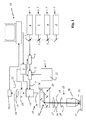
図1には、共焦点走査顕微鏡として形成されており、且つ、本発明による音響光学メインビームスプリッタが設けられている顕微鏡が示されている。 FIG. 1 shows a microscope configured as a confocal scanning microscope and provided with an acousto-optic main beam splitter according to the invention.
顕微鏡は複数の光源1を含んでおり、それら複数の光源1の光は共線的な一次光束2へと結合される。具体的に、顕微鏡はダイオードレーザ3と、有利にはダイオード励起固体レーザ4(DPSSレーザ;diode pumped solid State laser)と、ヘリウムネオンレーザ5と、アルゴンイオンレーザ6と、を含んでおり、それらのレーザの放射光束は、ダイクロイックビームスプリッタ7によって結合される。続いて、結合された放射光束はAOTF(acousto optical tunable filter)8に到達し、このAOTF8は、結合された放射光束から特定の波長の光を選択し、更にその光を通過させることができる。このために、AOTF8には高周波源9の電磁高周波が印加される。ユーザは、PC10を介する入力によって、1つ又は複数の波長のいずれの波長を、更に案内される光が有するべきかを設定することができる。また、高周波源9の周波数は、自動的に顕微鏡によって相応に調整される。AOTF8内では、電磁高周波によって、所望の光を回折させるための力学的な波が形成される。
The microscope includes a plurality of
顕微鏡は更に音響光学ビームコンバイナ11を有しており、このビームコンバイナ11は、一方ではAOTF8から転送された光を受光し、他方では白色光源12の光を受光する。
The microscope further includes an acousto-optic beam combiner 11 which receives light transmitted from the AOTF 8 on the one hand and light from the
特にその種の白色光源12は、入射した一次光を、特にパルスレーザの光をスペクトル的に拡張する特別な光学素子を有することができ、例えばマイクロ構造光学素子及び/又はテーパファイバ及び/又はフォトニック結晶ファイバ及び/又はフォトニック結晶及び/又はフォトニックバンドギャップ材料及び/又は非線形性を誘導する同等の光学素子を有することができる。その種の光源は数10nmのスペクトル幅、特に数100nmのスペクトル幅の一次光を供給することができる。
In particular, such a
音響光学ビームコンバイナ11にも同様に、高周波源9から供給される電磁高周波が印加される。音響光学ビームコンバイナ11は、電磁高周波によって光ビームを偏向又は回折させるための力学的な波を形成することができる音響光学素子を含んでいる。力学的な波の形成は、AOTF8から転送される光と、白色光源12の光とが、相互に共線的な結合された一次光束として音響光学ビームコンバイナ11から出射されるように行われる。
Similarly, the acoustooptic beam combiner 11 is applied with an electromagnetic high frequency supplied from the
顕微鏡は更に音響光学メインビームスプリッタ13を含んでおり、この音響光学メインビームスプリッタ13は、一方では、1つの所望の波長の照明光14又は複数の所望の波長の照明光14を照明光ビームパス15に向けるタスクを有しており、他方では、試料ステージ17上に配置されて照明されている試料16に由来する、多色且つ共線性の検出光束18(破線で示されている)から、試料16において散乱及び/又は反射された照明光14の成分を除去するタスクを有している。
The microscope further includes an acousto-optic
音響光学メインビームスプリッタ13によって照明光ビームパス15に向けられた照明光14は、ビーム偏向装置24に到達する。ビーム偏向装置24は、第1のガルバノメータミラー25及び第2のガルバノメータミラー26を含んでいる。一次光2の残りの部分は、1つ又は複数の力学的な波による影響を受けずにビームトラップ(図示せず)に到達する。
The
照明光14はビーム偏向装置24から出射された後に、先ず走査レンズ27に到達し、続いてチューブレンズ28に到達し、最後に、照明光14を試料16表面又は試料16内に焦点合わせする対物レンズ29に到達する。
After the
ビーム偏向装置24は、照明光14の焦点を試料16にわたり又は試料16を通るように、有利には蛇行状に案内する。その際、第1のガルバノメータミラー25はX方向における偏向を担当し、第2のガルバノメータミラー26はY方向における偏向を担当する。
The
音響光学メインビームスプリッタ13にも、少なくとも1つの電磁高周波が印加され、それによって1つの周波数の少なくとも1つの力学的な波が形成される。電磁高周波の周波数を変更することによって、力学的な波の周波数を変更することができる。力学的な波の形成は、例えばピエゾ音波発生器によって行なうことができる。
The acousto-optic
力学的な波が伝播する、音響光学メインビームスプリッタ13の結晶(この図においては図示されていない)及び力学的な波の伝播方向は、試料16から到来する検出光束18に対して以下のように配向されている。つまり、音響光学メインビームスプリッタ13が、力学的な波を用いて、検出光束18の、第1の直線偏光方向及び照明波長を有している成分も、検出光束18の、第1の直線偏光方向に対して垂直な第2の直線偏光方向及び照明波長を有している成分も偏向させて、検出光束18から除去するように配向されている。検出光束18の残存成分19は共線的に結晶から出射され、またAONF(acousto optical notch filters)20、結像光学系21及び検出絞り22を通過した後に、有利には、マルチバンド検出器として形成されている検出器23に到達する。検出器23の電気信号は、更なる処理及び評価のためにPC10に伝送される。
The crystal (not shown in the figure) of the acousto-optic
顕微鏡は以下のように構成されている。即ち、照明光14としての1つの波長の光だけが照明光ビームパス15に向けられ、1つの波長の光だけが試料16から到来する検出光束18から除去されるのではなく、それと同時に、複数の異なる波長(及び2つの直線偏光方向)の照明光を検出光から除去するために、及び/又は、複数の異なる波長(及び2つの直線偏光方向)の照明光を照明光ビームパスに向けるために複数の力学的な波を使用することができ、その際、しかしながら有利には、音響光学メインビームスプリッタ13の結晶内の照明光波長毎にただ1つの力学的な波が形成されるように、顕微鏡は構成されている。
The microscope is configured as follows. That is, only the light of one wavelength as the
音響光学メインビームスプリッタ13には、ユーザが所望する照明光波長毎に、高周波源9によって形成される固有の電磁高周波が印加される。完全性を期すために、高周波源9がAONF20、音響光学ビームコンバイナ11、AOTF8及び音響光学メインビームスプリッタ13に対して供給する種々の高周波は通常の場合、異なる周波数を有していることを言及しておく。しかしながら、少なくとも2つの音響光学コンポーネントに対して同一の周波数の2つの高周波を使用できるように、音響光学コンポーネントを構成することも可能である。
A specific electromagnetic high frequency formed by the
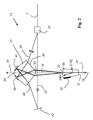
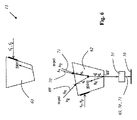
図2には、音響光学メインビームスプリッタ13の第1の実施例が概略的に示されている。
FIG. 2 schematically shows a first embodiment of the acousto-optic
音響光学メインビームスプリッタ13は偏光ビームスプリッタ33を含んでおり、この偏光ビームスプリッタ33は、例えば白色光源の複数の波長の偏光されていない一次光束を、特に偏光されていない広帯域の一次光束2を受光する。偏光ビームスプリッタ33は、一次光束2を第1の一次光束34及び第2の一次光束35へと空間的に分割し、その際、一次光束34,35の光は相互に垂直な直線偏光方向を有している。
The acousto-optic
音響光学メインビームスプリッタ13は、試料(この図においては図示していない)から到来する検出光束18(破線で示されている)のための入射面31と、最終的に検出器(この図においては図示していない)へと案内される検出光束18の残存成分19のための出射面32と、を備えている結晶30を含んでいる。残存成分19のための出射面32は、それと同時に第1の一次光束34及び第2の一次光束35を結晶30に入射させるための入射面でもある。
The acousto-optic
結晶30にはピエゾ音波発生器36が配置されており、このピエゾ音波発生器36には、1つの周波数の1つの電磁高周波又は複数の周波数の複数の電磁高周波が、1つの力学的な波又は複数の異なる力学的な波を形成するために印加される。1つ又は複数の力学的な波を用いて、第1の一次光束34からも、第2の一次光束35からも、1つの所望の照明光波長の光成分又は、複数の所望の照明光波長の光成分を回折によって偏向させ、それによって共線的に照明光ビームパス15に向けることができる。その際、各力学的な波のそれぞれ1つの周波数は(特にそれぞれがブラッグの条件を満たすために)、複数ある照明光波長のうちの1つの照明光波長に(2つの直線偏光方向に対して同時に)対応付けられている。
A piezoelectric
照明光14は、検出光束18のための入射面31を介して結晶30から出射される。従って、この入射面31は同時に照明光14のための出射面でもある。
The
同時に、1つの力学的な波を用いて、又は複数の力学的な波を用いて、検出光束18(破線で示されている)から、照明光14の1つ又は複数の波長を有している光成分が除去される。その際、結晶30及び(1つ又は複数の)力学的な波の伝播方向は、試料16から到来する検出光束18に対して以下のように配向されている。つまり、各力学的な波が、検出光束18の、第1の直線偏光方向及び照明波長を有している成分も、検出光束18の、第1の直線偏光方向に対して垂直な第2の直線偏光方向及び照明波長を有している成分も偏向させて、検出光束18から除去するように配向されている。検出光束18の残存成分19は、出射面32を介して共線的に結晶から出射される。図面においては、結晶構造の配向は結晶軸[001]及び[110]を示すことによって概略的に示唆されている。
At the same time, with one or more wavelengths of the
第1の一次光束34は、(検出光の回折された成分に関する)通常光の一次回折の方向とは反対に結晶30に入射され、他方、第2の一次光束35は、(検出光の回折された成分に関する)異常光の一次回折の方向とは反対に結晶30に入射される。このようにして、音響光学メインビームスプリッタを用いて一次光束2から所定の1つ又は複数の波長の照明光14を顕微鏡の照明光ビームパスに、従って試料に向けるために、全ての一次光束2が使用され、その際、各波長に関しては、単一の周波数の単一の力学的な波だけが必要とされる。
The first
結晶30から出射する照明光14の共線性を達成するために、結晶30の前段には分散光学コンポーネント37が設けられており、この分散光学コンポーネント37は、第1の一次光束34及び第2の一次光束35を空間的且つスペクトル的に分割し、その際、(特に角度及び/又は光路長の選択による)空間的な分割の程度は、それらが結晶30によって再び取り消されるように規定されている。
In order to achieve the collinearity of the
分散光学コンポーネント37は、第1の一次光束34のための入射兼出射窓38を有している。第1の一次光束34は先ず、入射兼出射窓38を介して、分散光学コンポーネント37に入射し、空間的且つスペクトル的に分割されて入射兼出射窓38を介して再び分散光学コンポーネント37から出射される前に、分散光学コンポーネント37を通った後に、入射兼出射窓38に対向する面に取り付けられている第1のミラー39によって反射される。
The dispersion
同様に、分散光学コンポーネント37は、偏向ミラー42によって偏向された第2の一次光束35のための別の入射兼出射窓40を有している。第2の一次光束35は先ず、入射兼出射窓40を介して、分散光学コンポーネント37に入射し、空間的且つスペクトル的に分割されて入射兼出射窓40を介して再び分散光学コンポーネント37から出射される前に、分散光学コンポーネント37を通った後に、入射兼出射窓40に対向する面に取り付けられている第2のミラー41によって反射される。
Similarly, the dispersion
更に分散光学コンポーネント37は、検出光束18の残存成分19のための、入射面43と、この入射面43に平行な出射面44と、を有している。検出光束18の残存成分19は、入射面43にも、それに平行な出射面44にも垂直に入射するので、従ってスペクトル的に分割されない。
Further, the dispersion
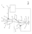
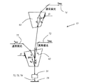
図3には、第1の結晶45及び第2の結晶46を有している、本発明による音響光学メインビームスプリッタ13の第2の実施例が示されている。
FIG. 3 shows a second embodiment of the acousto-optic
図示されている音響光学メインビームスプリッタ13は、複数の波長の光を含んでいる、図示されていない光源の一次光束47を受光する。一次光束はミラー48によって第1の結晶45の方向へと偏向され、出射窓49を介して第1の結晶45に入射する。試料から到来する検出光は出射窓を介して第1の結晶45から出射される(これについては下記において詳細に説明する)ことから、ここでは出射窓という用語を任意的に選択したことを明らかにしておく。
The illustrated acousto-optic
第1の結晶45には、第1のピエゾ音波発生器57が配置されている。第1のピエゾ音波発生器57には、高周波源9の周波数f1の電磁高周波が印加されており、またこの第1のピエゾ音波発生器57は、第1の結晶45を介して伝播される、周波数f1に対応する音響周波数の(図示していない)第1の力学的な波を形成する。
A first piezoelectric
力学的な波との相互作用によって、音響周波数に対応付けられている照明光波長の照明光が、試料16を照明するために照明光ビームパスへと偏向される。偏向された照明光は、入射窓50を介して第1の結晶45から出射され、特に少なくとも1つの走査装置及び顕微鏡対物レンズを含んでいる、顕微鏡の走査及び光学系ユニット51を介して、照明すべき試料16に到達する。
Due to the interaction with the mechanical wave, the illumination light of the illumination light wavelength associated with the acoustic frequency is deflected to the illumination light beam path to illuminate the
試料16に由来する検出光束18は、反対向きの光路を伝播して再び第1の結晶45に到達し、入射窓50を介してこの第1の結晶45に入射する。力学的な波との相互作用によって、検出光束の、第1の直線偏光方向及び照明光波長を有している第1の部分55が偏向されて、検出光束18から除去される。検出光束18の残存部分は、出射窓49を介して第1の結晶から出射され、続いて第2の結晶46の入射窓52に到達する。
The
第2の結晶46には、第2のピエゾ音波発生器53が配置されている。第2のピエゾ音波発生器53にもやはり高周波源9の周波数f1の電磁高周波が印加されており、またこの第2のピエゾ音波発生器53は、第2の結晶46を介して伝播される、周波数f1に対応する音響周波数の(図示していない)第2の力学的な波を形成する。
A second piezo-
第2の結晶46内を伝播する第2の力学的な波との相互作用によって、検出光束の、第1の直線偏光方向に対して垂直な第2の直線偏光方向及び照明光波長を有している第2の部分56が偏向されて、検出光束18から除去される。検出光束18の残存部分は、出射窓54を介して第2の結晶46から出射され、続いて図示していない検出器に到達する。
Due to the interaction with the second mechanical wave propagating in the
同一の音響周波数の音波によって、2つの結晶45,46において連続的に、検出光束の、第1の直線偏光方向及び照明光波長を有している第1の部分55も、検出光束の、第1の直線偏光方向に対して垂直な第2の直線偏光方向及び照明光波長を有している第2の部分56も偏向できることは、それらの結晶45,46が、少なくとも1つのパラメータに関して、例えば結晶カット面及び/又は結晶方位及び/又は力学的な波及び光の伝播方向に関して、偏向すべき光に対するブラッグの条件をそれぞれ満たしているように相互に異なっており、且つ相互に調整されていることによって達成されている。
The
結晶は、検出器に供給すべき検出光が共線的な光束としてメインビームスプリッタ13から出射されるように形成及び配置されている。
The crystal is formed and arranged so that detection light to be supplied to the detector is emitted from the
図4には、本発明による音響光学メインビームスプリッタ13の第3の実施例が示されている。
FIG. 4 shows a third embodiment of an acousto-optic
この音響光学メインビームスプリッタ13は、図3に図示した音響光学メインビームスプリッタ13に実質的に類似する構造を有しているが、しかしながらこの図4のメインビームスプリッタ13では、第1の入光部58を介して第1の一次光束34が入射され、第2の入光部59及び偏向ミラー61を介して第2の一次光束35が入射される。第1の一次光束34は、第1の直線偏光方向を有しており、それに対し第2の一次光束35は、第1の直線偏光方向に対して垂直な第2の直線偏光方向を有している。各結晶45,46内を伝播する力学的な波との相互作用によって、一次光束34,35の各々から、音響周波数に対応付けられている波長を有している成分が、試料16を照明するための照明光ビームパスに向けられる。
The acoustooptic
検出器(図示せず)に供給すべき検出光は、共線的な光束として出光部60を介してメインビームスプリッタ13から出射される。
Detection light to be supplied to a detector (not shown) is emitted from the
音響周波数を変更することによって、別の波長の成分を、試料16を照明するための照明光ビームパスに向けることができる。
By changing the acoustic frequency, another wavelength component can be directed to the illumination light beam path for illuminating the
図5には、本発明による音響光学メインビームスプリッタ13の第4の実施例が示されているが、ここでは図面を見やすくするために、試料16から到来する検出光の軌道、及び、照明光波長λ1及びλ2を有している成分の、試料16から到来する検出光からの除去のみが示されている。
FIG. 5 shows a fourth embodiment of the acousto-optic
音響光学メインビームスプリッタ13は第1の結晶62を有しており、この第1の結晶62には第1のピエゾ音波発生器75が配置されている。第1のピエゾ音波発生器75には、周波数f1及びf2の2つの電磁高周波が印加されており、またこの第1のピエゾ音波発生器75は、第1の結晶62を介して伝播される、各周波数f1及びf2に対応するそれぞれ1つの音響周波数の(図示していない)2つの力学的な波を形成する。
The acousto-optic
第1の結晶62及び力学的な波の伝播方向は、第1の結晶62についてはその結晶構造に関して、以下のように相互に相対的に、また、それぞれが結晶に入射する検出光束18に相対的に配向されている。つまり、力学的な波によって、検出光束18の、第1の直線偏光方向及び照明光波長λ1及びλ2を有している成分も、検出光束18の、第1の直線偏光方向に対して垂直な第2の直線偏光方向及び照明光波長λ1及びλ2を有している成分も偏向されて、検出光束18から除去されるように配向されている。
The propagation directions of the
図中、除去された成分は参照符号oe及びeoで表されている。第1の直線偏光方向は、この実施例において、第1の結晶62の複屈折特性に関する通常光の直線偏光方向であり、それに対し第2の直線偏光方向は、この実施例において、第1の結晶62の複屈折特性に関する異常光の直線偏光方向である。参照符号oe及びeoによって、入射する検出光の直線偏光方向は力学的な波との相互作用によって、(通常光から異常光、又は、通常光から異常光へと)それぞれ90°回転されることを表している。
In the figure, the removed components are represented by reference signs oe and eo. In this embodiment, the first linear polarization direction is the linear polarization direction of normal light related to the birefringence characteristics of the
音響光学メインビームスプリッタ13は、第2の結晶63を更に有しており、この第2の結晶63は、第1の結晶62から出射された残存検出光を受光する。この検出光は空間的に、その偏光に関しても、またその波長に関しても分割されている。しかしながら第2の結晶63は、自身から出射されて(図示していない)検出器へと供給される検出光束18が共線的に結合されるように構成されている。このことは、第1の結晶62の入射窓64が第2の結晶63の出射窓65に対して平行に配置されており、また付加的に、第1の結晶62の出射窓66が第2の結晶63の入射窓64に対して平行に配置されていることによって達成されている。
The acoustooptic
第2の結晶63は一方では、(第1の結晶62の力学的な波との相互作用にもかかわらず)、場合によっては未だなお検出光に残存する、照明光波長λ1及びλ2の成分を除去するために使用される。第2の結晶63は他方では、試料に向けられる照明光のための少なくとも1つの別の入射面を提供するために使用されるが、これはここでは詳細に図示されていない。
On the one hand, the
第2の結晶63には第2のピエゾ音波発生器68が配置されている。第2のピエゾ音波発生器68には、周波数f1’及びf2’の2つの電磁高周波が印加されており、またこの第2のピエゾ音波発生器68は、第2の結晶63を介して伝播される、各周波数f1’及びf2’に対応するそれぞれ1つの音響周波数の(図示していない)2つの力学的な波を形成する。
A second piezoelectric
第2の結晶63及び力学的な波の伝播方向は、第2の結晶63についてはその結晶構造に関して、以下のように相互に相対的に、また、それぞれが結晶に入射する検出光束18に相対的に配向されている。つまり、力学的な波によって、検出光束18の、第1の直線偏光方向及び照明光波長λ1及びλ2を有している成分も、検出光束18の、第1の直線偏光方向に対して垂直な第2の直線偏光方向及び照明光波長λ1及びλ2を有している成分も偏向されて、検出光束18から除去されるように配向されている。
The propagation directions of the
図6には、第1の直線偏光方向も、その第1の直線偏光方向とは異なる第2の直線偏光方向も有している、照明光波長λ1及びλ2の照明光が、図3に関連させて既に詳細に説明した音響光学メインビームスプリッタ13を用いて、試料16を照明するための照明光ビームパスにどのように向けられるかが示されている。
In FIG. 6, the illumination light of the illumination light wavelengths λ1 and λ2 having both the first linear polarization direction and a second linear polarization direction different from the first linear polarization direction is related to FIG. Thus, it is shown how the acousto-optic
以下の説明においては、第1の結晶62を介して、その結晶62内を伝播する(図示していない)力学的な波との相互作用があった照明光についてのみ説明する。しかしながら、択一的又は付加的に、第2の結晶63を介して照明光を入射させ、試料16を照明するための照明光ビームパスに向けることも可能である。
In the following description, only illumination light that has interacted with a mechanical wave (not shown) propagating through the
照明光の入射は、図6に示されているように、検出光の、照明光波長を有している成分が検出光束18から除去される光路において行われる。
As shown in FIG. 6, the illumination light is incident on the optical path where the component of the detection light having the illumination light wavelength is removed from the
第1の結晶62の特別な結晶カット面に基づき、(図中「o−pol」が付されている)第1の直線偏光方向及び二つの照明光波長λ1及びλ2を有している第1の照明光束69が、共線的な照明光束として入射される。力学的な波との相互作用によって、光は試料16を照明するための照明光ビームパスに向けられる。また光は、特に少なくとも1つの走査装置及び顕微鏡対物レンズを含んでいる、顕微鏡の走査及び光学系ユニット51を介して、照明すべき試料16に到達する。
Based on the special crystal cut surface of the
更に、第2の直線偏光方向と、照明光波長λ1の光と、を有している第2の照明光束70、並びに、照明光波長λ2の光と、同様に第2の直線偏光方向と、を有している第3の照明光束71が、空間的に別個の照明光束70,71として入射される。これらの照明光束70,71の光も、第1の結晶62内を伝播する力学的な波との相互作用によって、照明光ビームパスに到達し、また顕微鏡の走査及び光学系ユニット51を介して試料16に到達する。
Furthermore, the second
照明光波長λ1又は照明光波長λ2を有していない光は、照明光ビームパスには向けられずに、図示していないビームトラップに向けられる。 Light that does not have the illumination light wavelength λ1 or the illumination light wavelength λ2 is not directed to the illumination light beam path, but is directed to a beam trap (not shown).
図7には、STED顕微鏡における特別な使用可能性に関する第4の実施例が示されており、ここでは、試料に照射される照明光の軌道のみが示されており、図面を見やすくするために、検出光の軌道は図示していない。 FIG. 7 shows a fourth embodiment relating to a special possibility of use in the STED microscope, in which only the trajectory of the illumination light applied to the sample is shown, in order to make the drawing easier to see. The trajectory of the detection light is not shown.
共焦点走査顕微鏡の解像能力は、特に、試料における励起光束の焦点の空間的な大きさ及び強度分布によって定まる。蛍光の用途に関する解像能力を向上させるための装置は、国際公開第95/21393号から公知である。その装置においては、励起光束の焦点体積の横方向の縁部領域が、別の波長の別の光束の、いわゆる脱励起光束の、必要に応じて特別に成形された焦点でもって照明され、その縁部領域では、励起光束によって励起された試料領域が誘導放出されて基底状態に戻る。その場合、脱励起光束によって照明されない領域から自然放射される光だけが検出されるので、その結果、総じて解像度の向上が達成される。この方法については、STED(Stimulated Emission Depletion)と言う名称が定着している。 The resolution capability of the confocal scanning microscope is determined in particular by the spatial size and intensity distribution of the focal point of the excitation light beam in the sample. An apparatus for improving the resolution capability for fluorescent applications is known from WO 95/21393. In that device, the lateral edge region of the focal volume of the excitation beam is illuminated with a specially shaped focal point of a so-called de-excitation beam of another beam of another wavelength, if necessary In the edge region, the sample region excited by the excitation light beam is stimulated and released to return to the ground state. In that case, only the light naturally emitted from the region that is not illuminated by the deexcitation light flux is detected, and as a result, the resolution is improved as a whole. About this method, the name STED (Stimulated Emission Depletion) has been established.
図7に示されている実施例においては、音響光学メインビームスプリッタ13が、異なる方向から到来し、且つ波長λexc及び異なる直線偏光をそれぞれが有している2つの励起光束72,73も、波長λdepの脱励起光も、試料16を照明するための照明光ビームパスに向けるために使用される。
In the embodiment shown in FIG. 7, the acousto-optic
第1の結晶62のピエゾ音波発生器75には、周波数f1の高周波が印加されており、またこの第1のピエゾ音波発生器75は、第1の結晶62を介して伝播される、周波数f1に対応する音響周波数の(図示していない)力学的な波を形成する。
A high frequency of
励起光は第1の結晶62を介して入射し、また脱励起光は第2の結晶63を介して入射する。励起光は、第1の直線偏光方向(第1の結晶62の複屈折特性に関する通常直線偏光)を有している第1の励起光束72として、また、第1の直線偏光方向に対して垂直な直線偏光方向(第1の結晶62の複屈折特性に関する通常直線偏光)を有している第2の励起光束73として入射する。2つの励起光束72,73は、力学的な波との相互作用によって偏向され、相互に共軸に延びて、試料16を照明するための照明光ビームパスへと向けられる。
Excitation light is incident through the
第2の結晶63のピエゾ音波発生器68には、周波数f2の高周波が印加されており、またこの第2のピエゾ音波発生器68は、第2の結晶63を介して伝播される、周波数f2に対応する音響周波数の(図示していない)力学的な波を形成する。この力学的な波との相互作用によって、第2の結晶63の複屈折特性に関する通常直線偏光方向を有している、波長λdepの脱励起光束74は、照明光ビームパスに向けられ、最終的に試料16に到達する。
A high frequency of frequency f2 is applied to the piezoelectric
更に、脱励起光束74の直線偏光方向に対して垂直な直線偏光方向を有している別の脱励起光束を入射させることも可能である。これによって例えば、脱励起光束74によって誘導放出が行われる試料領域とは異なる試料領域において、その別の脱励起光束によって、誘導放出を行うことができる。
Furthermore, another deexcitation light beam having a linear polarization direction perpendicular to the linear polarization direction of the
この実施例においても、その偏光に依存せずに、検出光の、照明光波長を有している成分が、試料に由来する検出光束から除去される。 Also in this embodiment, the component having the illumination light wavelength of the detection light is removed from the detection light beam derived from the sample without depending on the polarization.
しかしながら、上記において詳細に説明したように、この実施例においても、励起光の波長λexcを有している成分が、試料から到来する検出光束から除去される。 However, as described in detail above, also in this embodiment, the component having the wavelength λexc of the excitation light is removed from the detected light beam coming from the sample.
本発明を特別な実施の形態に関連させて説明した。しかしながら、別紙の特許請求の範囲の保護範囲から逸脱することなく、種々の変更及び修正を行えることは明らかである。 The invention has been described with reference to particular embodiments. However, it will be apparent that various changes and modifications can be made without departing from the scope of protection of the appended claims.
Claims (21)
前記音響光学メインビームスプリッタにおいて、前記照明光波長に対応付けられている音響周波数の1つの力学的な波が伝播されるか、又は、前記照明光波長に対応付けられており、且つ、同一の音響周波数を有している複数の力学的な波が伝播され、
a.試料から到来する検出光束から、前記1つの力学的な波との相互作用によって、又は、前記複数の力学的な波との相互作用によって、前記検出光束の、第1の直線偏光方向及び前記照明光波長を有している成分も、前記検出光束の、前記第1の直線偏光方向に対して垂直な第2の直線偏光方向及び前記照明光波長を有している成分も偏向されて、前記検出光束から除去される、及び/又は、
b.前記1つの力学的な波との相互作用によって、又は、前記複数の力学的な波との相互作用によって、第1の直線偏光方向及び事前に選択された前記照明光波長を有している照明光の成分も、前記第1の直線偏光方向とは異なる、特に前記第1の直線偏光方向に対して垂直な第2の直線偏光方向及び事前に選択された前記照明光波長を有している照明光の成分も、試料を照明するための照明光ビームパスに向けられる、
ことを特徴とする、音響光学メインビームスプリッタ。 Configuration and definition to direct illumination light of a pre-selected or pre-selectable illumination light wavelength to an illumination light beam path for illuminating the sample, and to direct detection light coming from the sample to the detection light beam path In an acousto-optic main beam splitter for a scanning microscope,
In the acousto-optic main beam splitter, one dynamic wave having an acoustic frequency associated with the illumination light wavelength is propagated, or associated with the illumination light wavelength, and the same A plurality of mechanical waves having acoustic frequencies are propagated,
a. A first linear polarization direction and the illumination of the detected light beam from the detected light beam coming from the sample by interaction with the one dynamic wave or by interaction with the plurality of dynamic waves The component having the light wavelength is also deflected by the component having the second linear polarization direction perpendicular to the first linear polarization direction and the illumination light wavelength of the detection light beam, Removed from the detected light flux and / or
b. Illumination having a first linear polarization direction and a preselected illumination light wavelength by interaction with the one mechanical wave or by interaction with the plurality of mechanical waves The light component also has a second linear polarization direction that is different from the first linear polarization direction, in particular perpendicular to the first linear polarization direction, and the preselected illumination light wavelength. The component of the illumination light is also directed to the illumination light beam path for illuminating the sample,
An acousto-optic main beam splitter.
前記第1の結晶内に存在し、且つ、前記音響周波数を有している第1の力学的な波との相互作用によって、前記第1の直線偏光方向及び前記照明光波長を有している成分が偏向されて、前記検出光束から除去され、
前記第2の結晶内に存在し、同様に前記音響周波数を有している第2の力学的な波との相互作用によって、前記第2の直線偏光方向及び前記照明光波長を有している成分が偏向され、それによって前記検出光束から除去される、
請求項1に記載の音響光学メインビームスプリッタ。 The acousto-optic main beam splitter has a first crystal and a second crystal, and the first crystal and the second crystal are arranged so that the detection light beam passes continuously. And
It has the first linear polarization direction and the illumination light wavelength by interaction with a first mechanical wave that exists in the first crystal and has the acoustic frequency. The component is deflected and removed from the detected beam,
Having the second linear polarization direction and the illumination light wavelength by interaction with a second mechanical wave that is present in the second crystal and also has the acoustic frequency. The component is deflected and thereby removed from the detected light flux,
The acousto-optic main beam splitter according to claim 1.
b.前記第1の結晶の格子構造に対する前記検出光束の伝播方向の配向は、前記第2の結晶の格子構造に対する前記検出光束の伝播方向の配向とは異なる、及び/又は、
c.前記第1の結晶の格子構造に対する前記第1の力学的な波の伝播方向の配向は、前記第2の結晶の格子構造に対する前記第2の力学的な波の伝播方向の配向とは異なる、
請求項2に記載の音響光学メインビームスプリッタ。 a. The first crystal is different from the second crystal with respect to shape and / or size and / or crystal cut plane, and / or
b. The orientation of the detection light beam in the propagation direction relative to the lattice structure of the first crystal is different from the orientation of the detection light beam in the propagation direction relative to the lattice structure of the second crystal, and / or
c. The orientation of the first mechanical wave propagation direction relative to the lattice structure of the first crystal is different from the orientation of the second mechanical wave propagation direction relative to the lattice structure of the second crystal.
The acoustooptic main beam splitter according to claim 2.
b.前記検出光束は、先ず前記第1の結晶を通過し、続けて前記第2の結晶を通過し、前記第2の結晶の力学的な波との相互作用によって、前記照明光波長の照明光が照明光ビームパスに向けられる、
請求項2又は3に記載の音響光学メインビームスプリッタ。 a. The detected light beam first passes through the first crystal, and then passes through the second crystal. By the interaction with the dynamic wave of the first crystal, the illumination light having the wavelength of the illumination light is transmitted. Directed to the illumination light beam path and / or
b. The detected light beam first passes through the first crystal, and then passes through the second crystal. Due to the interaction with the mechanical wave of the second crystal, the illumination light having the wavelength of the illumination light is transmitted. Directed to the illumination light beam path,
The acousto-optic main beam splitter according to claim 2 or 3.
前記音響光学メインビームスプリッタが、前記力学的な波によって、前記検出光束の、第1の直線偏光方向及び前記照明光波長を有している成分も、前記検出光束の、前記第1の直線偏光方向に対して垂直な第2の直線偏光方向及び前記照明光波長を有している成分も偏向させて、前記検出光束から除去するように、前記結晶及び前記力学的な波の伝播方向は相互に相対的に、且つ、それぞれが前記結晶に入射する前記検出光束に相対的に配向されている、
請求項1乃至4のいずれか1項に記載の音響光学メインビームスプリッタ。 The acousto-optic main beam splitter has one crystal through which a dynamic wave propagates,
The acousto-optic main beam splitter also has a component having the first linear polarization direction and the illumination light wavelength of the detection light beam by the mechanical wave, and the first linear polarization of the detection light beam. The propagation direction of the crystal and the dynamic wave is mutually reciprocated so that the component having the second linear polarization direction perpendicular to the direction and the illumination light wavelength is also deflected and removed from the detection light beam. And each is relatively oriented with respect to the detection light flux incident on the crystal,
The acousto-optic main beam splitter according to any one of claims 1 to 4.
b.前記第2の直線偏光方向は、結晶の複屈折特性に関する異常光の直線偏光方向である、及び/又は、
c.前記第1の直線偏光方向又は前記第2の直線偏光方向は、前記力学的な波の伝播方向及び前記検出光束の伝播方向によって張られている平面内に配置されている、
請求項1乃至5のいずれか1項に記載の音響光学メインビームスプリッタ。 a. The first linear polarization direction is a normal light linear polarization direction related to the birefringence characteristics of the crystal, and / or
b. The second linear polarization direction is a linear polarization direction of extraordinary light related to the birefringence characteristics of the crystal, and / or
c. The first linear polarization direction or the second linear polarization direction is arranged in a plane stretched by the propagation direction of the dynamic wave and the propagation direction of the detection light beam,
The acousto-optic main beam splitter according to any one of claims 1 to 5.
請求項1乃至6のいずれか1項に記載の音響光学メインビームスプリッタ。 The beam guide component of the main beam splitter is arranged so that the remaining part of the detected light beam is emitted collinearly from the acousto-optic main beam splitter and / or the illumination light beam of a desired wavelength is in its polarization direction And arranged and configured to be collinearly integrated in the directed illumination light beam path, without depending on
The acoustooptic main beam splitter according to any one of claims 1 to 6.
前記第1の結晶内に存在し、且つ、音響周波数を有している第1の力学的な波との相互作用によって、第1の直線偏光方向及び前記照明光波長を有している照明光が試料を照明するために照明光ビームパスに向けられ、
前記第2の結晶内に存在し、且つ、音響周波数を有している第2の力学的な波との相互作用によって、前記第1の直線偏光方向とは異なる第2の直線偏光方向及び前記照明光波長を有している照明光が試料を照明するための前記照明光ビームパスに向けられる、
請求項1乃至7のいずれか1項に記載の音響光学メインビームスプリッタ。 The acousto-optic main beam splitter has a first crystal and a second crystal, and the first crystal and the second crystal are particularly arranged so that the detection light beam passes continuously. And
Illumination light having a first linear polarization direction and the illumination light wavelength by interaction with a first mechanical wave present in the first crystal and having an acoustic frequency. Is directed to the illumination light beam path to illuminate the sample,
A second linear polarization direction different from the first linear polarization direction by interaction with a second mechanical wave present in the second crystal and having an acoustic frequency; and Illumination light having an illumination light wavelength is directed to the illumination light beam path for illuminating the sample;
The acoustooptic main beam splitter according to any one of claims 1 to 7.
b.結晶内を伝播する前記力学的な波との相互作用によって、第1の直線偏光方向及び前記照明光波長を有している照明光も、特に垂直な別の第2の直線偏光方向及び前記照明光波長を有している照明光も、試料を照明するための前記照明光ビームパスに向けるように、前記音響光学メインビームスプリッタは構成されている、
請求項1乃至7のいずれか1項に記載の音響光学メインビームスプリッタ。 a. Due to the interaction with the mechanical wave propagating in the crystal, the first multicolored, preferably collinear, primary beam having the first linear polarization direction also has a second A primary luminous flux that is multicolored, preferably collinear, different from the first linear polarization direction, in particular having a second linear polarization direction perpendicular to the first linear polarization direction The acousto-optic main beam so as to divide the illumination light of the illumination light wavelength corresponding to the frequency of the dynamic wave and to direct the illumination light beam path to illuminate the sample. The splitter is configured, or
b. Due to the interaction with the mechanical wave propagating in the crystal, the illumination light having the first linear polarization direction and the illumination light wavelength can also be used in another vertical second linear polarization direction and the illumination. The acoustooptic main beam splitter is configured so that illumination light having a light wavelength is also directed to the illumination light beam path for illuminating the sample.
The acoustooptic main beam splitter according to any one of claims 1 to 7.
請求項1乃至9のいずれか1項に記載の音響光学メインビームスプリッタ。 The acousto-optic main beam splitter uses a plurality of dynamic waves, each characterized by a different acoustic frequency, to associate with the acoustic frequency scattered and / or reflected from the detected light beam at the sample. Removes components of illumination light having a plurality of illumination light wavelengths,
The acousto-optic main beam splitter according to any one of claims 1 to 9.
a.前記第1の結晶においては、それぞれが異なる照明光波長に対応付けられている異なる音響周波数によって特徴付けられている複数の力学的な波を用いて同時的に、第1の直線偏光方向及び前記音響周波数に対応付けられている複数の照明光波長を有している、試料において散乱及び/又は反射された照明光の成分が、前記検出光束から偏向され、
b.前記第2の結晶においては、前記第1の結晶の前記力学的な波と同じ音響周波数を有している複数の力学的な波を用いて同時的に、前記第1の直線偏光方向とは異なる第2の直線偏光方向及び前記音響周波数に対応付けられている複数の照明光波長を有している、試料において散乱及び/又は反射された照明光の成分が、検出光束から偏向される、
請求項1乃至10のいずれか1項に記載の音響光学メインビームスプリッタ。 The acousto-optic main beam splitter has a first crystal and a second crystal,
a. In the first crystal, a plurality of dynamic waves, each characterized by a different acoustic frequency associated with a different illumination light wavelength, are used simultaneously to form the first linear polarization direction and the A component of the illumination light scattered and / or reflected at the sample having a plurality of illumination light wavelengths associated with an acoustic frequency is deflected from the detected light flux;
b. In the second crystal, simultaneously with a plurality of mechanical waves having the same acoustic frequency as the mechanical wave of the first crystal, the first linear polarization direction is Components of illumination light scattered and / or reflected at the sample having a plurality of illumination light wavelengths associated with different second linear polarization directions and the acoustic frequencies are deflected from the detected light flux,
The acoustooptic main beam splitter according to any one of claims 1 to 10.
複数の力学的な波の各々は、その周波数に対応付けられている照明光波長を有しており、且つ第1の直線偏光方向を有している成分も、前記第1の直線偏光方向に対して垂直な第2の直線偏光方向を有している成分もそれぞれ偏向させて、検出光束から除去する、
請求項1乃至11のいずれか1項に記載の音響光学メインビームスプリッタ。 In the main beam splitter, particularly in the crystal of the main beam splitter, a plurality of dynamic waves characterized by different acoustic frequencies each associated with a different illumination light wavelength are propagated simultaneously,
Each of the plurality of mechanical waves has an illumination light wavelength associated with the frequency, and a component having the first linear polarization direction is also in the first linear polarization direction. The component having the second linear polarization direction perpendicular to the respective components is also deflected and removed from the detected light beam.
The acoustooptic main beam splitter according to any one of claims 1 to 11.
請求項1乃至12のいずれか1項に記載の音響光学メインビームスプリッタ。 The plurality of mechanical waves of the acousto-optic main beam splitter crystal have the same propagation direction and / or are formed by the same sound wave generator,
The acoustooptic main beam splitter according to any one of claims 1 to 12.
b.前記音響光学メインビームスプリッタは、異なる音響周波数を有している複数の力学的な波を用いて、多色の共線的な一次光束から、複数の照明光波長の照明光を分割させ、試料を照明するために照明光ビームパスに向ける、及び/又は、
c.前記音響光学メインビームスプリッタは、異なる音響周波数を有している複数の力学的な波を用いて、その都度、多色の、有利には共線的な、第1の直線偏光方向を有している少なくとも1つの光源の第1の一次光束からも、多色の、有利には共線的な、前記第1の直線偏光方向に対して垂直な第2の直線偏光方向を有している少なくとも1つの光源の第2の一次光束からも、それぞれ複数の波長の照明光を分割させ、試料を照明するために照明光ビームパスに向け、その際、各力学的な波の周波数にはそれぞれ複数ある照明光波長のうちの1つが対応付けられている、
請求項1乃至13のいずれか1項に記載の音響光学メインビームスプリッタ。 a. The acousto-optic main beam splitter divides illumination light of a plurality of illumination light wavelengths from multicolored primary light using a plurality of dynamic waves having different acoustic frequencies to illuminate a sample. Directing into the illumination light beam path and / or
b. The acousto-optic main beam splitter divides illumination light of a plurality of illumination light wavelengths from a multicolor collinear primary light beam using a plurality of dynamic waves having different acoustic frequencies, and a sample Directed to the illumination light beam path to illuminate and / or
c. The acousto-optic main beam splitter has a first linear polarization direction which is multicolored, preferably collinear, each time using a plurality of mechanical waves having different acoustic frequencies. The first primary luminous flux of the at least one light source also has a second linear polarization direction perpendicular to the first linear polarization direction, which is polychromatic, preferably collinear. The illumination light having a plurality of wavelengths is also divided from the second primary light flux of at least one light source, and directed to the illumination light beam path to illuminate the sample. One of the illumination light wavelengths is associated,
The acoustooptic main beam splitter according to any one of claims 1 to 13.
b.前記音響光学メインビームスプリッタは、一次光束を、第1の直線偏光方向を有している第1の成分と、特に垂直な別の第2の直線偏光方向を有している第2の成分と、に空間的に分割するための偏光ビームスプリッタを有する、
請求項1乃至14のいずれか1項に記載の音響光学メインビームスプリッタ。 a. The acousto-optic main beam splitter and / or the crystal of the main beam splitter is capable of splitting illumination light of a pre-selected or pre-selectable wavelength for illuminating the sample, the first linear polarization A first light entrance for a first primary light beam in a direction and a particularly vertical separate that can split the illumination light of a preselected or preselectable wavelength for illuminating the sample A second light incident portion for the second primary light flux in the second linear polarization direction, or
b. The acousto-optic main beam splitter includes a first component having a first linear polarization direction and a second component having another second linear polarization direction that is particularly perpendicular to the primary beam. A polarization beam splitter for spatially dividing the
The acousto-optic main beam splitter according to any one of claims 1 to 14.
請求項1乃至15のいずれか1項に記載の音響光学メインビームスプリッタ。 The illumination light directed to the illumination light beam path is emitted as a collinear illumination light beam from the acoustooptic main beam splitter and / or the crystal of the acoustooptic main beam splitter.
The acoustooptic main beam splitter according to any one of claims 1 to 15.
b.前記力学的な波が伝播する、前記音響光学メインビームスプリッタの結晶は、前記検出光のための入射面を有しており、該入射面を介して、前記検出光は0°の入射角で入射する、及び/又は、
c.前記力学的な波が伝播する、前記音響光学メインビームスプリッタの結晶は、前記検出光のための出射面を有している、及び/又は、
d.前記力学的な波が伝播する、前記音響光学メインビームスプリッタの結晶は、前記検出光のための出射面を有しており、該出射面を介して、前記検出光は0°の出射角で前記結晶から出射する、及び/又は、
e.前記力学的な波が伝播する、前記音響光学メインビームスプリッタの結晶は、前記検出光のための、入射面と、該入射面に対して平行に配向されている出射面と、を有している、
請求項1乃至16のいずれか1項に記載の音響光学メインビームスプリッタ。 a. The acousto-optic main beam splitter crystal through which the dynamic wave propagates has an entrance surface for the detection light, and / or
b. The crystal of the acousto-optic main beam splitter through which the dynamic wave propagates has an incident surface for the detection light, and the detection light has an incident angle of 0 ° through the incident surface. Incident and / or
c. The acousto-optic main beam splitter crystal through which the dynamic wave propagates has an exit surface for the detection light and / or
d. The crystal of the acousto-optic main beam splitter through which the dynamic wave propagates has an exit surface for the detection light, and the detection light has an exit angle of 0 ° through the exit surface. Emanating from the crystal and / or
e. The crystal of the acousto-optic main beam splitter through which the dynamic wave propagates has an entrance surface for the detection light and an exit surface oriented parallel to the entrance surface. Yes,
The acoustooptic main beam splitter according to any one of claims 1 to 16.
第1の結晶の入射窓は、第2の結晶の出射窓に対して平行に配置されており、
付加的に、前記第1の結晶の前記出射窓が前記第2の結晶の前記入射窓に対して平行に配置されている、
請求項1乃至17のいずれか1項に記載の音響光学メインビームスプリッタ。 Two crystals through which the detection light derived from the sample passes continuously through two crystals are provided in series,
The entrance window of the first crystal is arranged in parallel to the exit window of the second crystal,
In addition, the exit window of the first crystal is arranged parallel to the entrance window of the second crystal,
The acoustooptic main beam splitter according to any one of claims 1 to 17.
b.前記力学的な波が伝播する、前記音響光学メインビームスプリッタの結晶は、少なくとも1つの光源の前記一次光のための少なくとも1つの入射面を有しており、該入射面は同時に前記検出光のための出射面でもある、及び/又は、
c.前記力学的な波が伝播する、前記音響光学メインビームスプリッタの結晶は、前記照明光のための出射面を有しており、該出射面は同時に前記検出光のための入射面でもある、及び/又は、
d.前記力学的な波が伝播する、前記音響光学メインビームスプリッタの結晶は、少なくとも1つの光源の一次光のための入射面と、分割された照明光のための出射面と、を有しており、該入射面及び該出射面は、前記力学的な波を用いて偏向された照明光が0°の入射角で前記出射面に入射するように相互に配向されている、及び/又は、
e.前記力学的な波が伝播する、前記音響光学メインビームスプリッタの結晶は、少なくとも1つの光源の一次光のための入射面と、分割された照明光のための出射面と、を有しており、該入射面及び該出射面は、前記一次光が共線的な一次光束として結晶に入射でき、且つ、前記力学的な波を用いて偏向された照明光が共線的な照明光束として前記結晶から出射されるように相互に配向されている、
請求項1乃至18のいずれか1項に記載の音響光学メインビームスプリッタ。 a. The crystal of the acousto-optic main beam splitter through which the dynamic wave propagates has at least one entrance surface for the primary light of at least one light source and / or
b. The acousto-optic main beam splitter crystal, through which the dynamic wave propagates, has at least one entrance surface for the primary light of at least one light source, the entrance surface simultaneously of the detection light. And / or an exit surface for
c. The crystal of the acousto-optic main beam splitter through which the dynamic wave propagates has an exit surface for the illumination light, the exit surface being also the entrance surface for the detection light; and Or
d. The crystal of the acousto-optic main beam splitter through which the dynamic wave propagates has an entrance surface for primary light of at least one light source and an exit surface for split illumination light. The entrance surface and the exit surface are oriented relative to each other such that illumination light deflected using the mechanical wave is incident on the exit surface at an incident angle of 0 °, and / or
e. The crystal of the acousto-optic main beam splitter through which the dynamic wave propagates has an entrance surface for primary light of at least one light source and an exit surface for split illumination light. The incident surface and the exit surface allow the primary light to enter the crystal as a collinear primary light beam, and the illumination light deflected by using the dynamic wave serves as the collinear illumination light beam. Mutually oriented to be emitted from the crystal,
The acoustooptic main beam splitter according to any one of claims 1 to 18.
b.前記音響光学メインビームスプリッタは、少なくとも1つの分散光学コンポーネントを有しており、該分散光学コンポーネントは、前記力学的な波が伝播する、前記音響光学メインビームスプリッタの結晶によって(少なくとも部分的に)惹起される前記一次光及び/又は前記照明光及び/又は前記検出光の空間的な色分割を補償し、且つ、複数の入射面を有している、及び/又は、
c.前記音響光学メインビームスプリッタは、少なくとも1つの分散光学コンポーネントを有しており、該分散光学コンポーネントは、前記力学的な波が伝播する、前記音響光学メインビームスプリッタの結晶によって(少なくとも部分的に)惹起される前記一次光及び/又は前記照明光及び/又は前記検出光の空間的な色分割を補償し、且つ、第1の直線偏光方向を有している光のための第1の入射面と、前記第1の直線偏光方向に対して垂直な第2の直線偏光方向を有している光のための第2の入射面と、を有している、
請求項1乃至19のいずれか1項に記載の音響光学メインビームスプリッタ。 a. The acousto-optic main beam splitter has at least one dispersive optical component that is (at least partially) due to the crystal of the acousto-optic main beam splitter through which the mechanical wave propagates. Compensate for the spatial color division of the primary light and / or the illumination light and / or the detection light caused and / or
b. The acousto-optic main beam splitter has at least one dispersive optical component that is (at least partially) due to the crystal of the acousto-optic main beam splitter through which the mechanical wave propagates. Compensates for the spatial color division of the primary light and / or the illumination light and / or the detection light caused, and has a plurality of entrance planes, and / or
c. The acousto-optic main beam splitter has at least one dispersive optical component that is (at least partially) due to the crystal of the acousto-optic main beam splitter through which the mechanical wave propagates. A first entrance surface for light that compensates for the spatial color separation of the primary light and / or the illumination light and / or the detection light that is caused and has a first linear polarization direction And a second entrance surface for light having a second linear polarization direction perpendicular to the first linear polarization direction,
The acoustooptic main beam splitter according to any one of claims 1 to 19.
Applications Claiming Priority (5)
| Application Number | Priority Date | Filing Date | Title |
|---|---|---|---|
| DE102013217496.9 | 2013-09-03 | ||
| DE102013217496 | 2013-09-03 | ||
| DE102013227104.2A DE102013227104B4 (en) | 2013-09-03 | 2013-12-23 | Scanning microscope and acousto-optic main beam splitter for a scanning microscope |
| DE102013227104.2 | 2013-12-23 | ||
| PCT/EP2014/068749 WO2015032821A1 (en) | 2013-09-03 | 2014-09-03 | Scanning microscope and acousto-optical main beam splitter for a scanning microscope |
Publications (2)
| Publication Number | Publication Date |
|---|---|
| JP2016532905A true JP2016532905A (en) | 2016-10-20 |
| JP6538694B2 JP6538694B2 (en) | 2019-07-03 |
Family
ID=52470509
Family Applications (1)
| Application Number | Title | Priority Date | Filing Date |
|---|---|---|---|
| JP2016539528A Active JP6538694B2 (en) | 2013-09-03 | 2014-09-03 | Scanning microscope and acousto-optic main beam splitter for said scanning microscope |
Country Status (6)
| Country | Link |
|---|---|
| US (1) | US9933686B2 (en) |
| EP (1) | EP3042232B1 (en) |
| JP (1) | JP6538694B2 (en) |
| CN (1) | CN105723270B (en) |
| DE (1) | DE102013227104B4 (en) |
| WO (1) | WO2015032821A1 (en) |
Cited By (1)
| Publication number | Priority date | Publication date | Assignee | Title |
|---|---|---|---|---|
| JP2023537415A (en) * | 2020-08-11 | 2023-08-31 | ライカ マイクロシステムズ シーエムエス ゲゼルシャフト ミット ベシュレンクテル ハフツング | beam splitting device |
Families Citing this family (9)
| Publication number | Priority date | Publication date | Assignee | Title |
|---|---|---|---|---|
| DE102013227103B4 (en) * | 2013-09-03 | 2018-05-30 | Leica Microsystems Cms Gmbh | Microscope with an acousto-optic device |
| LU93098B1 (en) * | 2016-06-03 | 2018-01-22 | Leica Microsystems | Method for adjusting the intensity of a light beam in an optical arrangement and associated optical arrangement |
| DE102016124004A1 (en) * | 2016-12-09 | 2018-06-14 | Leica Microsystems Cms Gmbh | Optical device with at least one spectrally selective component |
| DE102017119479A1 (en) * | 2017-08-25 | 2019-02-28 | Carl Zeiss Microscopy Gmbh | Optical arrangement for scanning excitation radiation and / or manipulation radiation in a laser scanning microscope and laser scanning microscope |
| US11029506B2 (en) * | 2018-04-20 | 2021-06-08 | Coluxa Inc. | Scanning microscope with multiplexed light sources |
| CN116841029A (en) * | 2018-07-02 | 2023-10-03 | 巴塞罗纳大学 | Designable multi-point illuminators, confocal filters, confocal microscopes |
| EP3882681A1 (en) * | 2020-03-10 | 2021-09-22 | Leica Instruments (Singapore) Pte. Ltd. | A concept for a microscope system with an led-based illumination system |
| EP4145218B1 (en) * | 2021-09-03 | 2025-07-09 | Leica Microsystems CMS GmbH | Optical filter device |
| WO2025214596A1 (en) * | 2024-04-10 | 2025-10-16 | Leica Microsystems Cms Gmbh | Acousto-optic system and optical device |
Citations (2)
| Publication number | Priority date | Publication date | Assignee | Title |
|---|---|---|---|---|
| JP2003522323A (en) * | 1998-12-28 | 2003-07-22 | アメルシャム・バイオサイエンシーズ・アクチボラグ | Fluorescence emission measurement device |
| JP2004537747A (en) * | 2001-07-30 | 2004-12-16 | ライカ ミクロジュステムス ハイデルベルク ゲーエムベーハー | Optical device and scanning microscope |
Family Cites Families (6)
| Publication number | Priority date | Publication date | Assignee | Title |
|---|---|---|---|---|
| WO1995021393A2 (en) | 1994-02-01 | 1995-08-10 | Stefan Hell | Process and device for optically measuring a point on a sample with high local resolution |
| DE19906757B4 (en) | 1998-02-19 | 2004-07-15 | Leica Microsystems Heidelberg Gmbh | microscope |
| DE19944355B4 (en) * | 1999-09-16 | 2004-11-18 | Leica Microsystems Heidelberg Gmbh | Optical arrangement |
| US6963398B2 (en) * | 2001-10-03 | 2005-11-08 | Olympus Optical Co., Ltd. | Laser scanning microscope |
| DE102006053187A1 (en) | 2006-11-09 | 2008-05-15 | Leica Microsystems Cms Gmbh | Acousto-optic component |
| DE102010033722A1 (en) * | 2010-08-07 | 2012-02-09 | Carl Zeiss Microimaging Gmbh | Method for eliminating unwanted radiation portions from light detected from illuminated sample by laser scanning microscope, involves passing acousto optical tunable filter through two pole components |
-
2013
- 2013-12-23 DE DE102013227104.2A patent/DE102013227104B4/en active Active
-
2014
- 2014-09-03 CN CN201480059315.1A patent/CN105723270B/en active Active
- 2014-09-03 JP JP2016539528A patent/JP6538694B2/en active Active
- 2014-09-03 US US14/916,520 patent/US9933686B2/en active Active
- 2014-09-03 WO PCT/EP2014/068749 patent/WO2015032821A1/en not_active Ceased
- 2014-09-03 EP EP14758921.2A patent/EP3042232B1/en active Active
Patent Citations (2)
| Publication number | Priority date | Publication date | Assignee | Title |
|---|---|---|---|---|
| JP2003522323A (en) * | 1998-12-28 | 2003-07-22 | アメルシャム・バイオサイエンシーズ・アクチボラグ | Fluorescence emission measurement device |
| JP2004537747A (en) * | 2001-07-30 | 2004-12-16 | ライカ ミクロジュステムス ハイデルベルク ゲーエムベーハー | Optical device and scanning microscope |
Cited By (2)
| Publication number | Priority date | Publication date | Assignee | Title |
|---|---|---|---|---|
| JP2023537415A (en) * | 2020-08-11 | 2023-08-31 | ライカ マイクロシステムズ シーエムエス ゲゼルシャフト ミット ベシュレンクテル ハフツング | beam splitting device |
| JP7669474B2 (en) | 2020-08-11 | 2025-04-28 | ライカ マイクロシステムズ シーエムエス ゲゼルシャフト ミット ベシュレンクテル ハフツング | Beam splitting devices |
Also Published As
| Publication number | Publication date |
|---|---|
| WO2015032821A1 (en) | 2015-03-12 |
| CN105723270A (en) | 2016-06-29 |
| DE102013227104B4 (en) | 2018-05-30 |
| US20160223882A1 (en) | 2016-08-04 |
| US9933686B2 (en) | 2018-04-03 |
| EP3042232B1 (en) | 2019-07-17 |
| CN105723270B (en) | 2019-10-22 |
| JP6538694B2 (en) | 2019-07-03 |
| DE102013227104A1 (en) | 2015-03-05 |
| EP3042232A1 (en) | 2016-07-13 |
Similar Documents
| Publication | Publication Date | Title |
|---|---|---|
| JP6538694B2 (en) | Scanning microscope and acousto-optic main beam splitter for said scanning microscope | |
| JP6530405B2 (en) | Beam combiner, acousto-optic beam combiner, light source, microscope and use | |
| US10132682B2 (en) | Microscope with an acousto-optical device | |
| EP3581899B1 (en) | Spectroscopic microscope, and spectroscopic observation method | |
| US10310243B2 (en) | Device and method for multispot scanning microscopy | |
| US9721326B2 (en) | Method and system for improving resolution in laser imaging microscopy | |
| US8718414B2 (en) | Acousto-optical tunable filter element | |
| CN105683818B (en) | Scanning microscope with polarized sample illumination | |
| JP2004537747A (en) | Optical device and scanning microscope | |
| JP6632531B2 (en) | Microscope having member for changing shape of focal point of illumination light | |
| JP5521901B2 (en) | Nonlinear microscope and nonlinear observation method | |
| JP2017102013A (en) | Scanning type microscope | |
| EP4145207B1 (en) | Optical filter device for illuminating a sample | |
| EP4145218B1 (en) | Optical filter device | |
| HK1038797B (en) | Arrangement for separation excitation light and emission light in a microscope | |
| HK1038797A1 (en) | Arrangement for separation excitation light and emission light in a microscope |
Legal Events
| Date | Code | Title | Description |
|---|---|---|---|
| A521 | Request for written amendment filed |
Free format text: JAPANESE INTERMEDIATE CODE: A523 Effective date: 20160315 Free format text: JAPANESE INTERMEDIATE CODE: A523 Effective date: 20160509 |
|
| A621 | Written request for application examination |
Free format text: JAPANESE INTERMEDIATE CODE: A621 Effective date: 20170901 |
|
| A977 | Report on retrieval |
Free format text: JAPANESE INTERMEDIATE CODE: A971007 Effective date: 20180808 |
|
| A131 | Notification of reasons for refusal |
Free format text: JAPANESE INTERMEDIATE CODE: A131 Effective date: 20180820 |
|
| A601 | Written request for extension of time |
Free format text: JAPANESE INTERMEDIATE CODE: A601 Effective date: 20181119 |
|
| A521 | Request for written amendment filed |
Free format text: JAPANESE INTERMEDIATE CODE: A523 Effective date: 20190116 |
|
| TRDD | Decision of grant or rejection written | ||
| A01 | Written decision to grant a patent or to grant a registration (utility model) |
Free format text: JAPANESE INTERMEDIATE CODE: A01 Effective date: 20190520 |
|
| A61 | First payment of annual fees (during grant procedure) |
Free format text: JAPANESE INTERMEDIATE CODE: A61 Effective date: 20190606 |
|
| R150 | Certificate of patent or registration of utility model |
Ref document number: 6538694 Country of ref document: JP Free format text: JAPANESE INTERMEDIATE CODE: R150 |
|
| R250 | Receipt of annual fees |
Free format text: JAPANESE INTERMEDIATE CODE: R250 |
|
| R250 | Receipt of annual fees |
Free format text: JAPANESE INTERMEDIATE CODE: R250 |
|
| R250 | Receipt of annual fees |
Free format text: JAPANESE INTERMEDIATE CODE: R250 |
|
| R250 | Receipt of annual fees |
Free format text: JAPANESE INTERMEDIATE CODE: R250 |