JP2016527660A - Reflective tray for backlight, including polymer dielectric multilayer reflector - Google Patents
Reflective tray for backlight, including polymer dielectric multilayer reflector Download PDFInfo
- Publication number
- JP2016527660A JP2016527660A JP2016516722A JP2016516722A JP2016527660A JP 2016527660 A JP2016527660 A JP 2016527660A JP 2016516722 A JP2016516722 A JP 2016516722A JP 2016516722 A JP2016516722 A JP 2016516722A JP 2016527660 A JP2016527660 A JP 2016527660A
- Authority
- JP
- Japan
- Prior art keywords
- article
- tray
- reflective
- dielectric multilayer
- polymer dielectric
- Prior art date
- Legal status (The legal status is an assumption and is not a legal conclusion. Google has not performed a legal analysis and makes no representation as to the accuracy of the status listed.)
- Withdrawn
Links
Images


Classifications
-
- G—PHYSICS
- G02—OPTICS
- G02B—OPTICAL ELEMENTS, SYSTEMS OR APPARATUS
- G02B6/00—Light guides; Structural details of arrangements comprising light guides and other optical elements, e.g. couplings
- G02B6/0001—Light guides; Structural details of arrangements comprising light guides and other optical elements, e.g. couplings specially adapted for lighting devices or systems
- G02B6/0011—Light guides; Structural details of arrangements comprising light guides and other optical elements, e.g. couplings specially adapted for lighting devices or systems the light guides being planar or of plate-like form
- G02B6/0033—Means for improving the coupling-out of light from the light guide
- G02B6/005—Means for improving the coupling-out of light from the light guide provided by one optical element, or plurality thereof, placed on the light output side of the light guide
- G02B6/0055—Reflecting element, sheet or layer
-
- G—PHYSICS
- G02—OPTICS
- G02B—OPTICAL ELEMENTS, SYSTEMS OR APPARATUS
- G02B5/00—Optical elements other than lenses
- G02B5/08—Mirrors
- G02B5/0816—Multilayer mirrors, i.e. having two or more reflecting layers
- G02B5/0825—Multilayer mirrors, i.e. having two or more reflecting layers the reflecting layers comprising dielectric materials only
- G02B5/0841—Multilayer mirrors, i.e. having two or more reflecting layers the reflecting layers comprising dielectric materials only comprising organic materials, e.g. polymers
-
- G—PHYSICS
- G02—OPTICS
- G02B—OPTICAL ELEMENTS, SYSTEMS OR APPARATUS
- G02B6/00—Light guides; Structural details of arrangements comprising light guides and other optical elements, e.g. couplings
- G02B6/0001—Light guides; Structural details of arrangements comprising light guides and other optical elements, e.g. couplings specially adapted for lighting devices or systems
- G02B6/0011—Light guides; Structural details of arrangements comprising light guides and other optical elements, e.g. couplings specially adapted for lighting devices or systems the light guides being planar or of plate-like form
- G02B6/0065—Manufacturing aspects; Material aspects
-
- G—PHYSICS
- G02—OPTICS
- G02B—OPTICAL ELEMENTS, SYSTEMS OR APPARATUS
- G02B6/00—Light guides; Structural details of arrangements comprising light guides and other optical elements, e.g. couplings
- G02B6/0001—Light guides; Structural details of arrangements comprising light guides and other optical elements, e.g. couplings specially adapted for lighting devices or systems
- G02B6/0011—Light guides; Structural details of arrangements comprising light guides and other optical elements, e.g. couplings specially adapted for lighting devices or systems the light guides being planar or of plate-like form
- G02B6/0081—Mechanical or electrical aspects of the light guide and light source in the lighting device peculiar to the adaptation to planar light guides, e.g. concerning packaging
- G02B6/0085—Means for removing heat created by the light source from the package
-
- G—PHYSICS
- G02—OPTICS
- G02B—OPTICAL ELEMENTS, SYSTEMS OR APPARATUS
- G02B6/00—Light guides; Structural details of arrangements comprising light guides and other optical elements, e.g. couplings
- G02B6/0001—Light guides; Structural details of arrangements comprising light guides and other optical elements, e.g. couplings specially adapted for lighting devices or systems
- G02B6/0011—Light guides; Structural details of arrangements comprising light guides and other optical elements, e.g. couplings specially adapted for lighting devices or systems the light guides being planar or of plate-like form
- G02B6/0081—Mechanical or electrical aspects of the light guide and light source in the lighting device peculiar to the adaptation to planar light guides, e.g. concerning packaging
- G02B6/0093—Means for protecting the light guide
-
- G—PHYSICS
- G02—OPTICS
- G02F—OPTICAL DEVICES OR ARRANGEMENTS FOR THE CONTROL OF LIGHT BY MODIFICATION OF THE OPTICAL PROPERTIES OF THE MEDIA OF THE ELEMENTS INVOLVED THEREIN; NON-LINEAR OPTICS; FREQUENCY-CHANGING OF LIGHT; OPTICAL LOGIC ELEMENTS; OPTICAL ANALOGUE/DIGITAL CONVERTERS
- G02F1/00—Devices or arrangements for the control of the intensity, colour, phase, polarisation or direction of light arriving from an independent light source, e.g. switching, gating or modulating; Non-linear optics
- G02F1/01—Devices or arrangements for the control of the intensity, colour, phase, polarisation or direction of light arriving from an independent light source, e.g. switching, gating or modulating; Non-linear optics for the control of the intensity, phase, polarisation or colour
- G02F1/13—Devices or arrangements for the control of the intensity, colour, phase, polarisation or direction of light arriving from an independent light source, e.g. switching, gating or modulating; Non-linear optics for the control of the intensity, phase, polarisation or colour based on liquid crystals, e.g. single liquid crystal display cells
- G02F1/133—Constructional arrangements; Operation of liquid crystal cells; Circuit arrangements
- G02F1/1333—Constructional arrangements; Manufacturing methods
- G02F1/1335—Structural association of cells with optical devices, e.g. polarisers or reflectors
- G02F1/1336—Illuminating devices
- G02F1/133615—Edge-illuminating devices, i.e. illuminating from the side
-
- G—PHYSICS
- G02—OPTICS
- G02B—OPTICAL ELEMENTS, SYSTEMS OR APPARATUS
- G02B6/00—Light guides; Structural details of arrangements comprising light guides and other optical elements, e.g. couplings
- G02B6/0001—Light guides; Structural details of arrangements comprising light guides and other optical elements, e.g. couplings specially adapted for lighting devices or systems
- G02B6/0011—Light guides; Structural details of arrangements comprising light guides and other optical elements, e.g. couplings specially adapted for lighting devices or systems the light guides being planar or of plate-like form
- G02B6/0081—Mechanical or electrical aspects of the light guide and light source in the lighting device peculiar to the adaptation to planar light guides, e.g. concerning packaging
- G02B6/0083—Details of electrical connections of light sources to drivers, circuit boards, or the like
-
- G—PHYSICS
- G02—OPTICS
- G02B—OPTICAL ELEMENTS, SYSTEMS OR APPARATUS
- G02B6/00—Light guides; Structural details of arrangements comprising light guides and other optical elements, e.g. couplings
- G02B6/0001—Light guides; Structural details of arrangements comprising light guides and other optical elements, e.g. couplings specially adapted for lighting devices or systems
- G02B6/0011—Light guides; Structural details of arrangements comprising light guides and other optical elements, e.g. couplings specially adapted for lighting devices or systems the light guides being planar or of plate-like form
- G02B6/0081—Mechanical or electrical aspects of the light guide and light source in the lighting device peculiar to the adaptation to planar light guides, e.g. concerning packaging
- G02B6/0086—Positioning aspects
- G02B6/0088—Positioning aspects of the light guide or other optical sheets in the package
Abstract
本開示は、ポリマー誘電体多層リフレクタ材料を含む反射トレイ(101)、前記反射トレイ一体型バックライトモジュール、前記バックライトモジュールを用いた物品、及びバックライトモジュールに有用な反射トレイの製造方法に関する。特に、本バックライトモジュールは、不必要な領域への光漏れを低減する傾向を有すると共に、バックライト及び/又はディスプレイの構成部品を少なくとも部分的に取り囲む、狭ベゼルを備える小型ユニットを形成する。The present disclosure relates to a reflection tray (101) including a polymer dielectric multilayer reflector material, the reflection tray integrated backlight module, an article using the backlight module, and a method of manufacturing the reflection tray useful for the backlight module. In particular, the backlight module forms a small unit with a narrow bezel that has a tendency to reduce light leakage into unwanted areas and at least partially surrounds the backlight and / or display components.
Description
電子デバイス、特に液晶ディスプレイ(LCD)を有するハンドヘルド式電子デバイスは、最適に配置された調光フィルム、リフレクタ、及び光導波路を有するバックライトを利用して、発光ダイオード(LED)などの高度な光源によって生成される光を効率的に分配している。小型サイズ及び狭ベゼルを維持しながらも、バックライトからの光は、照光を意図しない領域に漏出しないよう保証されることが望ましい。 Electronic devices, particularly handheld electronic devices with a liquid crystal display (LCD), utilize an optimally positioned dimming film, reflector, and backlight with a light guide to provide advanced light sources such as light emitting diodes (LEDs). Efficiently distributes the light produced by. While maintaining a small size and narrow bezel, it is desirable to ensure that light from the backlight does not leak into areas not intended for illumination.
本開示は、反射トレイ、反射トレイ一体型バックライトモジュール、バックライトモジュールを用いた物品、及びバックライトモジュールに有用な反射トレイの製造方法に関する。特に、本バックライトモジュールは、不必要な領域への光漏れを低減する傾向を有すると共に、バックライト及び/又はディスプレイの構成部品を少なくとも部分的に取り囲む、狭ベゼルを備える小型ユニットを形成する。一態様では、本開示は、側部、底部、及び上開口部を有する反射トレイを含む物品であって、前記反射トレイが、光導波路と、光導波路に光学的に結合された光源と、上開口部と直に隣接する少なくとも1つの調光フィルムと、を少なくとも部分的に囲むように構成され、前記反射トレイがポリマー誘電体多層リフレクタを含む物品を提供する。 The present disclosure relates to a reflection tray, a reflection tray integrated backlight module, an article using the backlight module, and a method of manufacturing a reflection tray useful for the backlight module. In particular, the backlight module forms a small unit with a narrow bezel that has a tendency to reduce light leakage into unwanted areas and at least partially surrounds the backlight and / or display components. In one aspect, the present disclosure is an article that includes a reflective tray having a side, a bottom, and an upper opening, the reflective tray including a light guide, a light source optically coupled to the light guide, and a top. An article is provided that is configured to at least partially surround at least one light management film immediately adjacent to the opening, wherein the reflective tray includes a polymer dielectric multilayer reflector.
別の態様では、本開示は、側部、底部、及び上開口部を有する反射トレイと、底部と上開口部との間に配設される、光導波路及び光導波路と光学的に結合された光源と、上開口部と直に隣接する少なくとも1つの調光フィルムと、を含む物品であって、前記反射トレイがポリマー誘電体多層リフレクタを含む物品を提供する。 In another aspect, the present disclosure is optically coupled to an optical waveguide and an optical waveguide disposed between a reflective tray having sides, a bottom, and an upper opening, and the bottom and upper opening. An article comprising a light source and at least one light management film immediately adjacent to an upper opening, wherein the reflective tray comprises a polymer dielectric multilayer reflector.
別の態様では、本開示は、反射トレイ底部(前記反射トレイ底部は角部を有する)の底外周部に沿ってポリマー誘電体多層リフレクタに切り込みを入れる工程と、ポリマー誘電体多層リフレクタの反射トレイ底部の外方かつ角部に隣接する部分を除去する工程と、ポリマー誘電体多層リフレクタを底外周部に沿って折り曲げ、反射トレイ底部に対して垂直方向に延在する側部と、上開口部とを有する反射トレイを形成する工程とを含む方法を提供する。 In another aspect, the present disclosure provides an incision in a polymer dielectric multilayer reflector along a bottom perimeter of a reflector tray bottom (the reflector tray bottom has corners); and the reflector tray of the polymer dielectric multilayer reflector Removing the outer portion of the bottom and adjacent to the corner; bending the polymer dielectric multilayer reflector along the outer periphery of the bottom; a side extending perpendicular to the bottom of the reflective tray; and an upper opening Forming a reflective tray having:
上記の概要は、本開示の開示されるそれぞれの実施形態又は全ての実現形態を説明することを目的としたものではない。以下の図面及び詳細な説明により、実例となる実施形態をより具体的に例示する。 The above summary is not intended to describe each disclosed embodiment or every implementation of the present disclosure. Illustrative embodiments are more specifically illustrated by the following drawings and detailed description.
本明細書を通して、添付の図面を参照し、同じ参照番号は同じ要素を示す。
図は必ずしも縮尺に従っていない。図中用いられる同様の数字は、同様の要素を示す。しかしながら、所与の図中の構成要素を指す数字の使用は、同一数字を付された別の図中の構成要素を限定するものではないことが理解されよう。 The figures are not necessarily to scale. Like numbers used in the figures indicate like elements. However, it will be understood that the use of numbers to refer to components in a given figure does not limit components in another figure that are numbered identically.
本開示は、反射トレイ、反射トレイ一体型バックライトモジュール、バックライトモジュールを用いた物品、及びバックライトモジュールに有用な反射トレイの製造方法に関する。特に、本バックライトモジュールは、不必要な領域への光漏れを低減する傾向を有すると共に、バックライト及び/又はディスプレイの構成部品を少なくとも部分的に取り囲む、狭ベゼルを備える小型ユニットを形成する。 The present disclosure relates to a reflection tray, a reflection tray integrated backlight module, an article using the backlight module, and a method of manufacturing a reflection tray useful for the backlight module. In particular, the backlight module forms a small unit with a narrow bezel that has a tendency to reduce light leakage into unwanted areas and at least partially surrounds the backlight and / or display components.
特定の一実施形態では、本開示は、リフレクタを切り取って折り曲げ、光源、光導波路、及び1つ以上の調光フィルムを囲む反射トレイを形成できるテンプレートを提供する。前記反射トレイはLCDパネル近傍に配置された上部開口面を有し、前記上部開口面は、光がLCDを通過し、かつ光源、光導波路、又は調光フィルム周辺からの光漏れを防止するようにLCDを部分的に取り囲むか、又はLCDの表面と付着する。 In one particular embodiment, the present disclosure provides a template that can be cut and folded to form a reflective tray that surrounds a light source, a light guide, and one or more light management films. The reflection tray has an upper opening surface disposed in the vicinity of the LCD panel, and the upper opening surface prevents light from passing through the LCD and preventing light from leaking around the light source, the optical waveguide, or the light control film. Partially surrounds the LCD or adheres to the surface of the LCD.
リフレクタは、拡散リフレクタ、鏡面リフレクタ、半鏡面リフレクタなどの任意の好適なリフレクタであってよい。リフレクタは、金属又は合金、ポリマーコーティングされた金属又は合金、有機又は無機の誘電体多層リフレクタ、並びにこれらの組み合わせなど、種々の材料から作製することができる。特定の一実施形態では、リフレクタは、3M Companyから入手可能なVikuiti(商標)ESR(強化型鏡面リフレクタ)などのポリマー誘電体多層リフレクタであることが好ましい。調光フィルムは、通常、当業者に周知されている、1つ以上の反射偏光フィルム、拡散フィルム、微細構造化輝度向上フィルム、又はこれらの組み合わせを含む。 The reflector may be any suitable reflector such as a diffuse reflector, a specular reflector, a semi-specular reflector. The reflector can be made from a variety of materials such as metals or alloys, polymer-coated metals or alloys, organic or inorganic dielectric multilayer reflectors, and combinations thereof. In one particular embodiment, the reflector is preferably a polymer dielectric multilayer reflector such as Vikuiti ™ ESR (Enhanced Specular Reflector) available from 3M Company. The light management film typically comprises one or more reflective polarizing films, diffusion films, microstructured brightness enhancement films, or combinations thereof, as is well known to those skilled in the art.
以下の記述において、本明細書の一部を構成し、例示の目的で示されている添付図面を参照する。他の実施形態が企図され、本開示の範囲又は趣旨から逸脱することなく作製され得ることを理解するべきである。以下の詳細な説明はしたがって、限定的な意味で解釈されるものではない。 In the following description, reference is made to the accompanying drawings that form a part hereof and are shown for illustrative purposes. It is to be understood that other embodiments are contemplated and may be made without departing from the scope or spirit of the present disclosure. The following detailed description is therefore not to be taken in a limiting sense.
本明細書で使用される全ての科学用語及び専門用語は、特に指示がない限り、当該技術分野において一般的に用いられる意味を有する。本明細書にて与えられる定義は、本明細書でしばしば用いられる特定の用語の理解を促進しようとするものであり、本開示の範囲を限定するものではない。 All scientific and technical terms used herein have meanings commonly used in the art unless otherwise specified. The definitions provided herein are intended to facilitate understanding of certain terms often used herein and are not intended to limit the scope of the present disclosure.
特に断りがない限り、本明細書及び「特許請求の範囲」で用いられる特徴の大きさ、量、及び物理的特性を表わす全ての数字は、いずれの場合においても「約」なる語によって修飾されているものとして理解されるべきである。それ故に、そうでないことが示されない限り、前述の明細書及び添付の特許請求の範囲で示される数値パラメータは、本明細書で開示される教示内容を用いて当業者により、目標対象とする所望の特性に応じて、変化し得る近似値である。 Unless otherwise noted, all numbers representing the size, amount, and physical characteristics of features used in the specification and claims are qualified in each case by the term “about”. Should be understood as being. Therefore, unless indicated to the contrary, the numerical parameters set forth in the foregoing specification and the appended claims are intended to be targeted by those skilled in the art using the teachings disclosed herein. It is an approximate value that can vary depending on the characteristics of
本明細書及び添付の特許請求の範囲で用いられる場合、「a」、「an」、及び「the」などの単数形は、その内容によって別段の明確な指示がなされていない限りは、複数の指示対象を有する実施形態を包含する。本明細書及び添付の特許請求の範囲で用いられる場合、用語「又は」は、その内容によって別段の明確な指示がなされていない限りは、一般に「及び/又は」を含む意味で用いられる。 As used in this specification and the appended claims, the singular forms “a”, “an”, and “the” include plural numbers unless the content clearly dictates otherwise. Including an embodiment having a pointing object. As used herein and in the appended claims, the term “or” is generally employed in its sense including “and / or” unless the content clearly dictates otherwise.
これらに限定されるものではないが、「下側」、「上側」、「下」、「下方」、「上方」、及び「〜の上」などの空間的に関連した語は、本明細書で使用される場合、ある要素の別の要素に対する空間的関係を述べるうえで説明を容易にする目的で用いられる。このような空間的に関連した語には、図に示され本明細書に述べられる特定の向き以外に、使用中又は作動中の装置の異なる向きが含まれる。例えば、図中で示される対象物が反転又は裏返されている場合、他の要素の下方又は下として前に説明された部分は、これらの他の要素の上となるであろう。 Spatial terms such as, but not limited to, “lower”, “upper”, “lower”, “lower”, “upper”, and “upper” are used herein. Is used for ease of explanation in describing the spatial relationship of one element to another. Such spatially related terms include different orientations of the device in use or in operation other than the particular orientation shown in the figures and described herein. For example, if the object shown in the figure is flipped or flipped, the parts previously described as below or below other elements will be above these other elements.
本明細書で使用されるとき、ある要素、部材若しくは層が、例えば、別の要素、部材若しくは層と「一致する境界面」を形成する、これらの「上にある」、これらと「接続される」、「結合される」、若しくは「接触する」として述べられる場合、その要素、部材若しくは層は、例えば、特定の要素、部材若しくは層の直接上にあるか、これらと直接接続されるか、直接結合されるか、直接接触してもよく、又は介在する要素、部材若しくは層が特定の要素、部材若しくは層の上にあるか、これらと接続されるか、結合されるか、若しくは接触しうる。例えばある要素、部材又は層が、別の要素の「直接上にある」、別の要素に「直接接続される」、「直接結合する」、又は「直接接触する」ものとして表される場合、介在する要素、部材又は層は存在しない。 As used herein, an element, member or layer is “on”, “connected to” these, for example to form a “coincident interface” with another element, member or layer. ”,“ Coupled ”, or“ contact ”, the element, member or layer is, for example, directly on or directly connected to a particular element, member or layer May be directly coupled, in direct contact, or intervening elements, members or layers may be on, connected to, coupled to, or in contact with particular elements, members or layers Yes. For example, if an element, member or layer is represented as being “directly on” another element, “directly connected”, “directly coupled” or “directly contacted”, There are no intervening elements, members or layers.
本明細書で使用されるとき、「有する(have、having)」、「含む(include、including、comprise、comprising)」などは、非限定的(open ended)な意味で用いられており、一般に「含むが、これらに限定されない」ことを意味する。用語「からなる(consisting of)」及び「から本質的になる(consisting essentially of)」は、「含む(comprising)」等の用語に包含されることが理解されよう。 As used herein, “have, having”, “include”, “comprise”, “comprising” and the like are used in an open-ended sense and are generally “ Including but not limited to ". It will be understood that the terms “consisting of” and “consisting essentially of” are encompassed by terms such as “comprising”.
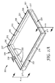
図1Aは、本開示の一態様による反射トレイを作製するために使用できる折り曲げ可能なテンプレート100の概略斜視図を示す。折り曲げ可能なテンプレート100は、第1の主表面112、反対側の第2の主表面114、及び外周部121を含む、反射シート110から作製される。外方部分118は、反射シート110の角部から除去されて、端部115を形成しており、任意の開口部119は、反射シートの厚み寸法を貫通している。外方部分118及び任意の開口部119は、例えばナイフ切断、ダイカット、打抜き、レーザー切断などの任意の好適な技術を使用して除去され得る。一般に、外周部121と平行かつ離れている切り込み線116は、他に記載されるように、反射シート110を容易に折り曲げ、側部及び底部を有する反射トレイを形成できるように、反射シート110の厚み寸法を部分的に貫通している。切り込みを入れる工程は、反射トレイに対して所望の数の側部を作製するように行うことができ、これにより、反射トレイは所望する1、2、3、4、又はそれ以上の数の側部を有し得る。切り込み線116は、例えば、熱的又は機械的なエンボス加工、ダイカット、キスカット、レーザー切り込みなどを含む、任意の好適な技術を使用して作製することができる。レーザー切り込みは、他に記載のような切り込み線116を形成する方法として好ましい。
FIG. 1A shows a schematic perspective view of a
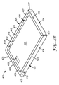
図1Bは、本開示の一態様によれば、図1Aの折り曲げ可能なテンプレート100から形成される反射トレイ101の概略斜視図を示す。反射トレイ101は、端部115のそれぞれが合わさって角部117を形成するように、切り込み線116と外周部121との間のそれぞれの部分を折り上げることによって形成される。反射トレイ101は、底部120、第1の4つの貫入側部122、124、126、及び128、上開口部129、並びに内表面112及び外表面114を含む。任意の開口部119は、他に記載するように、反射トレイ101内の構成部品の外部接続機構、トレイの外方から内方への電気配線の貫入路、外部光源からトレイの内方への光路などを目的として、底部120及び側部122、124、126、128のいずれか又はその全てに適宜配置される。
FIG. 1B shows a schematic perspective view of a
特定の一実施形態では、角部117は、各側面を互いに接合するための接着剤層(図示せず)又は接着テープ(図示せず)を含んでよい。場合によっては、角部117は、熱接着、超音波溶接、レーザー溶接、並びにスロット/タブ技術を含む機械的な方法など、当業者に周知されている、他の技術を介して互いに接合してよい。あるいは場合によっては、反射トレイ101は、Vikuiti(商標)ESRフィルムなどの反射シート110から熱成形され得る。その場合、切り込み線116は任意であってよい。場合によっては、熱成形された反射トレイ101の角部117は、連続したフィルムの一部であり得る。次に、場合によっては、熱成形された反射トレイ101を、例えばレーザー切断、ナイフ切断、又はダイカットによる形成後、残りの反射シート110から除去してもよい。あるいは場合によっては、外方部分118を除去した後の反射シート110から反射トレイ101を熱成形し、上述のように角部117を互いに接合してよい。ESRフィルムのようなポリマーフィルムの熱成形は、当業者に既知である。
In one particular embodiment, the
内表面112及び/又は外表面114の所望の部分に、種々の層を適宜適用し得る。これらの層は任意であり、蒸着、接着、積層、又はそれ以外の方法で、対応する表面に付着されたコーティング、フィルム、及びシートを含んでよい。特定の一実施形態では、外表面114に適用される層は、例えば、熱伝導性層、光吸収層、構造支持層、これらの組み合わせなどであり得る。場合によっては、他に記載するように、反射トレイ101内に配置される光源(図示せず)からの熱抽出を補助するため、例えば、バインダー中の熱伝導粒子、又は金属フィルム若しくはシートを有する熱伝導性外層が有用であり得る。特定の一実施形態では、内表面112に適用される層は、拡散層、光吸収層、又はこれらの組み合わせであり得る。場合によっては、拡散層は好ましくは、反射トレイ101の、側部122、124、126、128又は底部120のうち、いずれか又は複数の内表面112に適用され得る。
Various layers may be applied as appropriate to desired portions of the
図2Aは、本開示の一態様による、バックライト物品200の概略斜視図を示している。図2Aに示されている要素201〜229のそれぞれは、既に説明した図1Bに示す同じ参照数字の要素101〜129に対応している。例えば、図2Aの角部217は図1Bの角部117に対応している、といった具合である。バックライト物品200は、側部222、224、226、228、底部220、内表面212、外表面214、切り込み線216、及び外周部221を有する反射トレイ201を含む。反射トレイ201は、側部228に隣接して配設される光源230、1つ以上のライト232(LED又は当技術分野において既知である他の光源)、及び反射トレイ201の外方に延在する電気的接続234を収容する。電気的接続234は、任意の開口部(図示せず、他に記載)を通り抜けるか、又は外周部221の上方を通る。光導波路基板などの光導波路240は、光源230と光学的に結合され、バックライト物品200の反射トレイ201内に配置され、側部222、224、226、228によって仕切られる。光導波路240及び光源230は、他の接続又は構造支持のために、任意の開口部(図示せず、他に記載)を通り抜ける部分を含んでよい。場合によっては、光源230の部分は、反射トレイ201の外部に位置してよく、このとき、光は任意の開口部を通過できる。
FIG. 2A shows a schematic perspective view of a
図2Bは、本開示の一態様による図2Aのバックライト物品200のA−A’断面を通るバックライトモジュール202の分解組立て略断面図を示す。図2Bに示されている要素201〜240のそれぞれは、既に説明した図2Aに示す同じ参照数字の要素201〜240に対応している。バックライトモジュール202は、側部224、228、底部220、内表面212、外表面214、切り込み線216、少なくとも1つのライト232を有する光源230、及び光源230に光学的に結合された光導波路240を有する反射トレイ201を含む。少なくとも1つの調光フィルムを有する調光フィルムスタック250は、上開口部229を通って、反射トレイ201内に設置するように配設される。上部表面262を有するLCDパネル260及び反対側の底面264は、調光フィルムスタック250に隣接して配置される。
FIG. 2B shows an exploded schematic cross-sectional view of the
図2Cは、本開示の一態様による、LCDパネル260を含むバックライトモジュール202の概略断面図を示している。図2Cに示されている要素201〜264のそれぞれは、既に説明した図2Bに示す同じ参照数字の要素201〜264に対応している。バックライトモジュール202は、側部224、228、底部220、内表面212、外表面214、切り込み線216、少なくとも1つのライト232を有する光源230、及び光源230に光学的に結合された光導波路240を有する反射トレイ201を含む。少なくとも1つの調光フィルムを有する調光フィルムスタック250は反射トレイ201内に配設され、上部表面262及び反対側の底面264を有するLCDパネル260は、調光フィルムスタック250に隣接して配置される。
FIG. 2C illustrates a schematic cross-sectional view of the
特定の一実施形態では、LCDパネル260は、図2Cに示すように反射トレイ201内に嵌合でき、更に側部224、228はそれぞれ、LCDパネル260、調光フィルムスタック250、光源230、及び光導波路240のうちの1つ又は複数と、接着剤層(図示せず)を介して取り付けされ得る。場合によっては、LCDパネル260の上部表面262は、図2Cに示すように、反射トレイ201の外周部221と同一の高さに揃っていてよい。場合によっては、LCDパネル260の上部表面262は、反射トレイ201の外周部221の上方又は下方に位置してよい。
In one particular embodiment, the
特定の一実施形態では、LCDパネル260は、他に記載したように、反射トレイ201より大きくてもよく、反射トレイ201の外周部221は、LCDパネル260の底面264(図示せず)に隣接して配置されていてよい。場合によっては、反射トレイ201の外周部221をLCDパネル260の底面264に、接着剤層(同様に図示せず)によって付着してよい。
In one particular embodiment, the
図2Dは、本開示の一態様による、LCDパネル260を含むバックライトモジュール203の概略断面図を示している。図2Dに示されている要素201〜264のそれぞれは、既に説明した図2Cに示す同じ参照数字の要素201〜264に対応している。バックライトモジュール203は、側部224、228、底部220、内表面212、外表面214、切り込み線216、少なくとも1つのライト232を有する光源230、及び光源230に光学的に結合された光導波路240を有する反射トレイ201を含む。少なくとも1つの調光フィルムを有する調光フィルムスタック250は反射トレイ201内に配設され、上部表面262及び反対側の底面264を有するLCDパネル260は、調光フィルムスタック250に隣接して配置される。フランジ272を有するフレーム270は、側部224、228の内表面212に隣接してLCDパネル260の周りに配置される。フランジ272は、図2Aに示す、側部222、226の内表面212にも隣接して延在し得ることが理解されよう。フランジ272は、バックライトモジュール203内の構成部品の支持体用に設けられ、各構成部品は、例えば接着剤又は機械的な手段によってフランジ272に取り付けることができる。場合によっては、フランジ272は、外周部221から底部220に向かって任意の距離にわたって延在することができ、更に底部220と接触するように延在し得る。反射トレイ201内の他の構成部品(すなわち光源230、光導波路240、調光フィルムスタック250、及びLCDパネル260)は、フランジ272を収容するように寸法設定される。
FIG. 2D shows a schematic cross-sectional view of a
図2Eは、本開示の一態様による、LCDパネル260を含むバックライトモジュール204の概略断面図を示している。図2Eに示されている要素201〜264のそれぞれは、既に説明した図2Dに示す同じ参照数字の要素201〜264に対応している。バックライトモジュール204は、側部224、228、底部220、内表面212、外表面214、切り込み線216、少なくとも1つのライト232を有する光源230、及び光源230に光学的に結合された光導波路240を有する反射トレイ201を含む。少なくとも1つの調光フィルムを有する調光フィルムスタック250は反射トレイ201内に配設され、上部表面262及び反対側の底面264を有するLCDパネル260は、調光フィルムスタック250に隣接して配置される。フランジ274を有するフレーム270は、側部224、228の外表面214に隣接して反射トレイ201の周りに配置される。フランジ274は、図2Aに示す、側部222、226の外表面214にも隣接して延在し得ることが理解されよう。フランジ274は、バックライトモジュール203内の構成部品の支持体用に設けられ、外表面214は、例えば接着剤又は機械的な手段によってフランジ274に取り付けることができる。場合によっては、フランジ274は、外周部221から底部220に向かって任意の距離にわたって延在でき、更に底部220を越えて延在し得る。
FIG. 2E illustrates a schematic cross-sectional view of the
特定の一実施形態では、図2Dに示すバックライトモジュール203内のフランジ272及び図2Eに示すバックライトモジュール204内のフランジ274の位置は、側部222、224、226、228の少なくともいずれかが、対応するフランジ内に部分的に格納され得る(図示せず)、すなわち部分的に格納される側部の内表面212及び外表面214の両方がフランジと接触するように組み合わせることができる。
In one particular embodiment, the location of the
図2Fは、本開示の一態様による、LCDパネル260を含むバックライトモジュール205の概略断面図を示している。図2Fに示されている要素201〜264のそれぞれは、既に説明した図2Cに示す同じ参照数字の要素201〜264に対応している。バックライトモジュール205は、側部224、228、底部220、内表面212、外表面214、切り込み線216、少なくとも1つのライト232を有する光源230、及び光源230に光学的に結合された光導波路240を有する反射トレイ201を含む。少なくとも1つの調光フィルムを有する調光フィルムスタック250は、図1Aに示すテンプレートに類似の方法によって、切り込みを入れられ及び折り曲げされ、反射トレイ201内に配設され、上部表面262及び反対側の底面264を有するLCDパネル260は、調光フィルムスタック250に隣接して配置される。LCDパネル260は、反射トレイ201より大きくてもよく、反射トレイ201の外周部221は、LCDパネル260の底面264に隣接して配置されていてよい。場合によっては、反射トレイ201の外周部221をLCDパネル260の底面264に、接着剤層(図示せず)によって付着してよい。
FIG. 2F illustrates a schematic cross-sectional view of the
図2Gは、本開示の一態様による、LCDパネル260を含むバックライトモジュール206の概略断面図を示している。図2Gに示されている要素201〜264のそれぞれは、既に説明した図2Cに示す同じ参照数字の要素201〜264に対応している。バックライトモジュール205は、側部224、228、底部220、内表面212、外表面214、切り込み線216、少なくとも1つのライト232を有する光源230、及び光源230に光学的に結合された光導波路240を有する反射トレイ201を含む。少なくとも1つの調光フィルムを有する調光フィルムスタック250の第1の部分は、図1Aに示すテンプレートに類似の方法によって、切り込みを入れられ及び折り曲げされ、反射トレイ201内に配設される。
FIG. 2G illustrates a schematic cross-sectional view of a
調光フィルムスタック250の第2の部分(例えば、図1Aに示すテンプレートに類似の方法によって、切り込みを入れられ及び折り曲げされる最上部のフィルム251)は、上開口部229にわたって延在し、側部224、228(本図には示されていないが、他に記載の側部222、226も同様)の外表面214に隣接して配設されるフラップ252として延在し得る。場合によっては、調光フィルムスタック250の第2の部分(例えば、図1Aに示すテンプレートに類似の方法によって、切り込みを入れられ及び折り曲げされる最上部のフィルム251)は、上開口部229にわたって延在することができ、側部224、228(本図には示されていないが、他に記載の側部222、226も同様)の内表面212(図示せず)に隣接して配設されるフラップ252として延在し得る。フラップ252を、例えば接着剤を使用して外表面214(あるいは内表面212)に接着し、それによって密閉された反射トレイ201を形成することが可能である。場合によっては、側部222、224、226、228のいずれか又は複数の外表面212又は内表面214に、外部接続機構の組み合わせを使用してもよい。上部表面262を有するLCDパネル260及び反対側の底面264は、調光フィルムスタック250の最上部フィルム251に隣接して配置され得る。
A second portion of the light management film stack 250 (eg, the
図2Hは、本開示の一態様による、LCDパネル260を含むバックライトモジュール207の概略断面図を示している。図2Hに示されている要素201〜264のそれぞれは、既に説明した図2Cに示す同じ参照数字の要素201〜264に対応している。バックライトモジュール207は、側部224、228、底部220、内表面212、外表面214、切り込み線216、少なくとも1つのライト232を有する光源230、及び光源230に光学的に結合された光導波路240を有する反射トレイ201を含む。少なくとも1つの調光フィルムを有する調光フィルムスタック250は、反射トレイ201内に配設される。図4A〜図4Bに関して、他に記載するように、反射トレイ201は上部229の一部の上方に延在する縁部225、239を含む。上部表面262を有するLCDパネル260及び反対側の底面264は、調光フィルムスタック250に隣接して配置される。LCDパネル260は、反射トレイ201より大きくてもよく、反射トレイ201の縁部225、239は、LCDパネル260の底面264に隣接して配置されていてよい。場合によっては、接着剤層(図示せず)は、反射トレイ201の縁部225、239をLCDパネル260の底面264に付着させることができる。場合によっては、調光フィルムスタック250の最上部フィルム(図2Gに示すものと同様)を、縁部225、239に隣接して配設して接着することができ、それにより、LCDパネル260の底部264に隣接して配置できる密閉された反射トレイ201を形成する。
FIG. 2H illustrates a schematic cross-sectional view of a
図3は、本開示の一態様による、LCDパネル360を含むバックライトモジュール300の概略斜視図を示している。図3に示されている要素301〜362のそれぞれは、既に説明した図2Cに示す同じ参照数字の要素201〜262に対応している。例えば、図3の角部317は図2Cの角部217に対応している、といった具合である。バックライトモジュール300は、側部322、324、326、328、底部320、外表面214、角部317、及び外周部321を有する反射トレイ301を含む。最上部262を有するLCDパネル360は、外周部321に隣接する反射トレイ301内に配置される。他に記載するように、第1の電気的接続334は、反射トレイ301内方の光源(図示せず)と連通し、反射トレイ301の外側に延在する。第2の電気的接続365は、反射トレイ301内方のLCDパネル360と連通し、反射トレイ301の外側に延在する。
FIG. 3 shows a schematic perspective view of a
図4Aは、本開示の一態様による反射トレイを作製するために使用できる折り曲げ可能なテンプレート400の概略斜視図を示す。折り曲げ可能なテンプレート400は、第1の主表面412、反対側の第2の主表面414、及び外周部421を含む、反射シート410から作製される。外方部分418は、反射シート410の角部から除去されて、端部415を形成しており、任意の開口部419は、反射シートの厚み寸法を貫通している。外方部分418及び任意の開口部419は、例えばナイフ切断、ダイカット、打抜き、レーザー切断などの任意の好適な技術を使用して除去され得る。一般に、外周部421と平行かつ離れている第1の切り込み線416は、他に記載されるように、反射シート410を容易に折り曲げ、側部及び底部を有するトレイを形成できるように、反射シート410の厚み寸法を部分的に貫通している。
FIG. 4A shows a schematic perspective view of a
一般に、外周部421及び第1の切り込み線416の両方に平行かつ離れている第2の切り込み線413は、他に記載されるように、反射シート410を容易に折り曲げ、側部、底部、及び縁部を有するトレイを形成できるように、反射シート410の厚み寸法を部分的に貫通している。
In general, a
特定の一実施形態では、第2の切り込み線413及び第1の切り込み線416は、どちらも第1の主表面412などの同一主表面に配設され得、後続の折り曲げによって、切り込み線沿い方向から見た場合、図4Bに示すような「C」形状を形成し得る。他に記載されるように、本実施形態では、縁部は底部上方の「トレイ内」に配設される。場合によっては、第2の切り込み線413及び第1の切り込み線416は、例えば、第1の切り込み線416が第1の主表面412上にあり、第2の切り込み線413が第2の主表面414上にあり得るように反対側の主表面に配設され得る。この場合、後続の折り曲げによって、切り込み線沿い方向から見たとき、「Z」形状を形成し得、縁部は「トレイ外」(図4Bには図示せず)に配設される。第1及び第2の切り込み線413、416のそれぞれの配置は、主表面が所望のトレイ形状を形成するために必要な位置でよく、場合によっては、縁部は所望数の側部のトレイ内又はトレイ外であり得ることが理解されよう。
In one particular embodiment, both the
第1及び第2の切り込み線416、413は、例えば、熱的又は機械的なエンボス加工、ダイカット、キスカット、レーザー切り込みなどを含む、任意の好適な技術を使用して作製することができる。レーザー切り込み法は、他に記載されるような第1及び第2の切り込み線416、413を形成する方法として好ましい。
The first and
図4Bは、本開示の一態様によれば、図4Aの折り曲げ可能なテンプレート400から形成される反射トレイ401の概略斜視図を示す。反射トレイ401は、端部415のそれぞれが合わさって角部417を形成するように、第1の切り込み線416と第2の切り込み線413と外周部421との間のそれぞれの部分を折り上げることにより形成される。反射トレイ401は、底部420、第1の4つの貫入側部422、424、426、及び428、上開口部429、上部開口面429の一部の上方に延在する(すなわちトレイ内の)第1の貫入縁部423、425、427、239、内表面412、並びに外表面414を含む。図4Aに関する考察から、反射シート410のどちらの主表面に第1及び第2の切り込み線416、413が配設されるかに応じて、第1の貫入縁部423、425、427、239が「トレイ内」(図4Bに示す)、「トレイ外」(図示せず)、又は「トレイ内」と「トレイ外」との組み合わせのいずれにも延在し得ることが理解されよう。任意の開口部419は、他に記載するように、反射トレイ401内の構成部品の取付機構として、又は電気配線などの貫入路として、底部420、側部422、424、426、428、及び縁部423、425、427、439のいずれか又はその全てに所望により配置される。反射トレイ401は、図2A〜2Hに示す反射トレイ201のいずれかと置き換え得ることが理解されよう。また、当業者であれば、反射トレイ201のいずれもが、「トレイ内」又は「トレイ外」のいずれかに延在する1つ以上の縁部を含み得ることも認識されよう。
FIG. 4B shows a schematic perspective view of a
特定の一実施形態では、角部417は、各側面を互いに接合するための接着剤層(図示せず)又は接着テープ(図示せず)を含んでよい。場合によっては、角部417は、熱接着、超音波溶接、レーザー溶接、並びにスロット/タブ技術を含む機械的な方法など、当業者に周知されている、他の技術を介して互いに接合してよい。場合によっては、反射トレイ401は、代替的にVikuiti(商標)のESRフィルムなどの反射シート410から熱成形され得、切り込み線413、416は任意であってもよい。場合によっては、熱成形された反射トレイ401の角部417は、連続したフィルムの一部であり得るが、その場合でも縁部423、425、427、239は連続していない角部417の一部を含み得る。次に、場合によっては、熱成形された反射トレイ401を、例えばレーザー切断、ナイフ切断、又はダイカットによる形成後、残りの反射シート410から除去してもよい。あるいは場合によっては、外方部分418を除去した後の反射シート410から反射トレイ401を熱成形し、上述のように角部417を互いに接合してよい。ESRフィルムのようなポリマーフィルムの熱成形は、当業者に既知である。
In one particular embodiment, the
内表面412及び/又は外表面414の所望の部分に、種々の層を適宜適用し得る。これらの層は任意であり、蒸着、接着、積層、又はそれ以外の方法で、対応する表面に付着されたコーティング、フィルム、及びシートを含んでよい。特定の一実施形態では、外表面414に適用される層は、例えば、熱伝導性層、光吸収層、これらの組み合わせなどであり得る。場合によっては、他に記載するように、反射トレイ401内に配置される光源(図示せず)からの熱抽出を補助するため、例えば、バインダー中の熱伝導粒子、又は金属フィルム若しくはシートを有する熱伝導性外層が有用であり得る。特定の一実施形態では、内表面412に適用される層は、拡散層、光吸収層、又はこれらの組み合わせであり得る。場合によっては、拡散層は好ましくは、反射トレイ401の、側部422、424、426、428のいずれか若しくは複数、縁部423、425、427、439のいずれか若しくは複数、又は底部420の内表面412に適用され得る。
Various layers may be applied as appropriate to desired portions of the
以下は、本開示の実施形態のリストである。 The following is a list of embodiments of the present disclosure.
項目1は、物品であって、側部、底部、及び上開口部を有する反射トレイを含み、前記反射トレイが、光導波路と、前記光導波路に光学的に結合された光源と、前記上開口部と直に隣接する少なくとも1つの調光フィルムと、を少なくとも部分的に囲むよう構成され、前記反射トレイがポリマー誘電体多層リフレクタを含む、物品である。 Item 1 is an article including a reflection tray having a side, a bottom, and an upper opening, the reflection tray including an optical waveguide, a light source optically coupled to the optical waveguide, and the upper opening And at least one light management film immediately adjacent to the section, the reflective tray comprising a polymer dielectric multilayer reflector.
項目2は、前記反射トレイがポリマー誘電体多層リフレクタから本質的になる、項目1の物品である。 Item 2 is the article of item 1, wherein the reflective tray consists essentially of a polymer dielectric multilayer reflector.
項目3は、前記反射トレイが、前記上開口部に隣接して配設される液晶ディスプレイ(LCD)を少なくとも部分的に囲むように構成され、その結果、少なくとも1つの調光フィルムを通過する前記光源からの光が前記LCDに進入する、項目1又は項目2の物品である。 Item 3 is configured such that the reflective tray at least partially surrounds a liquid crystal display (LCD) disposed adjacent to the upper opening, so that it passes through at least one light management film. Item 1 or Item 2 in which light from a light source enters the LCD.
項目4は、前記反射トレイが最大4つの側部を有する矩形の反射トレイである、項目1〜項目3の物品である。 Item 4 is the article of items 1 to 3, wherein the reflective tray is a rectangular reflective tray having a maximum of four sides.
項目5は、前記ポリマー誘電体多層リフレクタが、強化型鏡面リフレクタ(ESR)である、項目1〜項目4の物品である。 Item 5 is the article of items 1 to 4, wherein the polymer dielectric multilayer reflector is an reinforced specular reflector (ESR).
項目6は、前記反射トレイの外表面が、その上に配設された機能層を含む、項目1〜項目5の物品である。 Item 6 is the article of items 1 to 5 in which the outer surface of the reflective tray includes a functional layer disposed thereon.
項目7は、前記機能層が、熱伝導性層、光吸収層、構造層、又はこれらの組み合わせである、項目6の物品である。 Item 7 is the article of item 6, wherein the functional layer is a heat conductive layer, a light absorption layer, a structural layer, or a combination thereof.
項目8は、前記機能層が、バインダー中の熱伝導粒子、又は金属を含む、項目1〜項目6の物品である。 Item 8 is the article according to items 1 to 6, wherein the functional layer includes heat conductive particles in a binder or metal.
項目9は、前記側部及び前記底部のうちの少なくとも1つが、内表面の上に適用される拡散反射層を含む、項目1〜項目8の物品である。 Item 9 is the article of items 1-8, wherein at least one of the side and the bottom includes a diffuse reflective layer applied over the inner surface.
項目10は、前記側部及び前記底部のうちの少なくとも1つが、少なくとも1つの開口部を含む、項目1〜項目9の物品である。 Item 10 is the article of items 1-9, wherein at least one of the side and the bottom includes at least one opening.
項目11は、前記少なくとも1つの開口部が、電気的接続、光導波路支持体、光源支持体、調光フィルム支持体、外部光源からの光路、又はこれらの組み合わせを収容するように構成される、項目10の物品である。 Item 11 is configured such that the at least one opening accommodates an electrical connection, an optical waveguide support, a light source support, a light control film support, an optical path from an external light source, or a combination thereof. Item 10 item.
項目12は、前記少なくとも1つの調光フィルムが、反射偏光フィルム、拡散フィルム、微細構造化輝度向上フィルム、又はこれらの組み合わせを含む、項目1〜項目11の物品である。 Item 12 is the article of items 1 to 11 wherein the at least one light management film comprises a reflective polarizing film, a diffusion film, a microstructured brightness enhancement film, or a combination thereof.
項目13は、前記反射トレイが、熱成形されたESRフィルムである、項目1〜項目12の物品である。 Item 13 is the article of items 1 to 12, wherein the reflective tray is a thermoformed ESR film.
項目14は、前記反射トレイが、折り曲げられたESRフィルムである、項目1〜項目13の物品である。 Item 14 is the article of items 1 to 13, wherein the reflection tray is a folded ESR film.
項目15は、前記少なくとも1つの調光フィルムが、前記底部と平行な第1の表面及び少なくとも1つの側面と平行な第2の表面を有する折り曲げられたフィルムである、項目1〜項目14の物品である。 Item 15 is the article of items 1 to 14, wherein the at least one light management film is a folded film having a first surface parallel to the bottom and a second surface parallel to at least one side. It is.
項目16は、前記反射トレイが、前記底部と平行であり、かつ前記側部から前記上開口部の一部の上方又は前記上開口部の外方、又はこれらの組み合わせのいずれかに延在している縁部を更に含み、前記縁部が前記ポリマー誘電体多層リフレクタを含む、項目1〜項目15の物品である。 Item 16 is that the reflection tray is parallel to the bottom part and extends from the side part above a part of the upper opening part, outside the upper opening part, or a combination thereof. The article of items 1 to 15, further comprising an edge, wherein the edge comprises the polymer dielectric multilayer reflector.
項目17は、前記縁部が前記ポリマー誘電体多層リフレクタから本質的になる、項目16の物品である。 Item 17 is the article of item 16, wherein the edge consists essentially of the polymer dielectric multilayer reflector.
項目18は、物品であって、側部、底部、及び上開口部を有する反射トレイと、前記底部と前記上開口部との間に配設される、光導波路及び光導波路と光学的に結合された光源と、前記上開口部と直に隣接する少なくとも1つの調光フィルムと、を含み、前記反射トレイがポリマー誘電体多層リフレクタを含む、物品である。 Item 18 is an article, which is optically coupled to a reflection tray having a side, a bottom, and an upper opening, and an optical waveguide and an optical waveguide disposed between the bottom and the upper opening. And an at least one light management film immediately adjacent to the upper opening, wherein the reflective tray includes a polymer dielectric multilayer reflector.
項目19は、前記反射トレイがポリマー誘電体多層リフレクタから本質的になる、項目18の物品である。
項目20は、前記ポリマー誘電体多層リフレクタが強化型鏡面リフレクタ(ESR)である、項目19の物品である。
Item 20 is the article of
項目21は、前記上開口部に隣接して配設される液晶ディスプレイ(LCD)を更に含み、その結果、前記少なくとも1つの調光フィルムを通過する光源からの光が前記LCDに進入する、項目18〜項目20の物品である。 Item 21 further includes a liquid crystal display (LCD) disposed adjacent to the upper opening so that light from a light source passing through the at least one light management film enters the LCD. 18 to 20 items.
項目22は、前記LCDの外周部周囲に延在しているフレームを更に含み、前記反射トレイの前記側部がフレームの内方又はフレームの外方にある、項目21の物品である。 Item 22 is the article of item 21, further comprising a frame extending around the periphery of the LCD, wherein the side of the reflective tray is on the inside of the frame or on the outside of the frame.
項目23は、方法であって、角部を有する反射トレイ底部の底外周部に沿ってポリマー誘電体多層リフレクタに切り込みを入れる工程と、前記ポリマー誘電体多層リフレクタの前記反射トレイ底部の外方かつ前記角部に隣接する部分を除去する工程と、前記ポリマー誘電体多層リフレクタを前記底外周部に沿って折り曲げ、前記反射トレイ底部に対して垂直方向に延在する側部と、上開口部とを有する反射トレイを形成する工程と、を含む方法である。 Item 23 is a method, comprising: cutting a polymer dielectric multilayer reflector along a bottom perimeter of a reflective tray bottom having a corner; and an outer side of the reflective tray bottom of the polymer dielectric multilayer reflector and Removing a portion adjacent to the corner, bending the polymer dielectric multilayer reflector along the bottom outer periphery, a side extending in a direction perpendicular to the bottom of the reflection tray, and an upper opening Forming a reflection tray having
項目24は、前記反射トレイ底部が矩形形状及び4つの角部を有し、除去された前記ポリマー誘電体多層リフレクタの前記部分が前記4つの角部それぞれと隣接する90°角を含む、項目23の方法である。 Item 24 is the item 23, wherein the bottom of the reflective tray has a rectangular shape and four corners, and the portion of the removed polymer dielectric multilayer reflector includes a 90 ° angle adjacent to each of the four corners. It is a method.
項目25は、前記ポリマー誘電体多層リフレクタを底外周部の外方に側部の高さで切り込みを入れる工程と、ポリマー誘電体多層リフレクタを側部の高さの切り込みに沿って折り曲げ、前記反射トレイ底部と平行であり、かつ前記側部から前記反射トレイ底部一部の上方、前記上開口部の外方、又はこれらの組み合わせに延在している縁部を形成する工程と、を更に含む、項目23又は項目24の方法である。 Item 25 is a step of cutting the polymer dielectric multilayer reflector at a side height outside the outer periphery of the bottom, bending the polymer dielectric multilayer reflector along a side height cut, and Forming an edge that is parallel to the bottom of the tray and that extends from the side to the top of the reflective tray bottom, to the outside of the upper opening, or a combination thereof. , Item 23 or Item 24.
項目26は、切り込みを入れる工程がレーザー切り込み、熱切り込み、機械的切り込み、又はこれらの組み合わせを含む、項目25の方法である。 Item 26 is the method of item 25, wherein the incision step includes laser incision, thermal incision, mechanical incision, or a combination thereof.
特に断りがない限り、本明細書及び特許請求の範囲において用いられる特徴の大きさ、量、及び物理特性を表す数値は全て、「約」なる語によって修飾されているものとして理解すべきである。それ故に、そうでないことが示されない限り、前述の明細書及び添付の特許請求の範囲で示される数値パラメータは、本明細書で開示される教示内容を用いて当業者により、目標対象とする所望の特性に応じて、変化し得る近似値である。 Unless otherwise indicated, all numerical values representing the size, amount, and physical characteristics of features used in the specification and claims are to be understood as being modified by the word “about”. . Therefore, unless indicated to the contrary, the numerical parameters set forth in the foregoing specification and the appended claims are intended to be targeted by those skilled in the art using the teachings disclosed herein. It is an approximate value that can vary depending on the characteristics of
本明細書に引用される全ての参考文献及び刊行物は、それらが本開示と直接矛盾し得る場合を除き、それらの全容を参照によって本開示に明確に援用するものである。以上、本明細書において具体的な実施形態を図示、説明したが、様々な代替的かつ/又は等価的な実現形態を、図示及び説明された具体的な実施形態に本開示の範囲を逸脱することなく置き換えることができる点は、当業者であれば認識されるところであろう。本出願は、本明細書において検討される具体的な実施形態のいかなる適合例又は変形例をも網羅しようとするものである。したがって、本開示は、特許請求の範囲及びその等価物によってのみ限定されるものとする。 All references and publications cited herein are expressly incorporated herein by reference in their entirety, unless they may be in direct conflict with the present disclosure. While specific embodiments have been illustrated and described herein, various alternative and / or equivalent implementations may depart from the scope of the disclosure in the specific embodiments illustrated and described. Those skilled in the art will recognize that they can be replaced without any problems. This application is intended to cover any adaptations or variations of the specific embodiments discussed herein. Accordingly, the present disclosure is intended to be limited only by the following claims and equivalents thereof.
Claims (26)
側部、底部、及び上開口部を有する反射トレイを含み、前記反射トレイが、
光導波路と、
前記光導波路に光学的に結合された光源と、
前記上開口部と直に隣接する少なくとも1つの調光フィルムと、を少なくとも部分的に囲むように構成され、
前記反射トレイがポリマー誘電体多層リフレクタを含む、物品。 Goods,
A reflective tray having a side, a bottom, and an upper opening, the reflective tray comprising:
An optical waveguide;
A light source optically coupled to the optical waveguide;
Configured to at least partially surround at least one light management film immediately adjacent to the upper opening,
An article, wherein the reflective tray comprises a polymer dielectric multilayer reflector.
側部、底部、及び上開口部を有する反射トレイと、
前記底部と前記上開口部との間に配設される、光導波路及び前記光導波路と光学的に結合された光源と、
前記上開口部と直に隣接する少なくとも1つの調光フィルムと、を含み、
前記反射トレイがポリマー誘電体多層リフレクタを含む、物品。 Goods,
A reflective tray having side, bottom, and top openings;
An optical waveguide disposed between the bottom and the upper opening, and a light source optically coupled to the optical waveguide;
Including at least one light control film immediately adjacent to the upper opening,
An article, wherein the reflective tray comprises a polymer dielectric multilayer reflector.
角部を有する反射トレイ底部の底外周部に沿ってポリマー誘電体多層リフレクタに切り込みを入れる工程と、
前記ポリマー誘電体多層リフレクタの前記反射トレイ底部の外方かつ前記角部に隣接する部分を除去する工程と、
前記ポリマー誘電体多層リフレクタを前記底外周部に沿って折り曲げ、前記反射トレイ底部に対して垂直方向に延在する側部と、上開口部とを有する反射トレイを形成する工程と、を含む方法。 A method,
Cutting the polymer dielectric multilayer reflector along the bottom perimeter of the bottom of the reflective tray having corners;
Removing the portion of the polymer dielectric multilayer reflector that is outside the bottom of the reflective tray and adjacent to the corner;
Bending the polymer dielectric multilayer reflector along the bottom perimeter to form a reflective tray having sides that extend perpendicular to the bottom of the reflective tray and an upper opening. .
Applications Claiming Priority (3)
| Application Number | Priority Date | Filing Date | Title |
|---|---|---|---|
| US201361829494P | 2013-05-31 | 2013-05-31 | |
| US61/829,494 | 2013-05-31 | ||
| PCT/US2014/039524 WO2014193803A1 (en) | 2013-05-31 | 2014-05-27 | Reflective tray for a backlight, comprising a polymeric dielectric multilayer reflector |
Publications (2)
| Publication Number | Publication Date |
|---|---|
| JP2016527660A true JP2016527660A (en) | 2016-09-08 |
| JP2016527660A5 JP2016527660A5 (en) | 2017-06-22 |
Family
ID=51022447
Family Applications (1)
| Application Number | Title | Priority Date | Filing Date |
|---|---|---|---|
| JP2016516722A Withdrawn JP2016527660A (en) | 2013-05-31 | 2014-05-27 | Reflective tray for backlight, including polymer dielectric multilayer reflector |
Country Status (6)
| Country | Link |
|---|---|
| US (1) | US20160124139A1 (en) |
| JP (1) | JP2016527660A (en) |
| KR (1) | KR20160014684A (en) |
| CN (1) | CN105247410A (en) |
| TW (1) | TW201504730A (en) |
| WO (1) | WO2014193803A1 (en) |
Families Citing this family (3)
| Publication number | Priority date | Publication date | Assignee | Title |
|---|---|---|---|---|
| KR102331265B1 (en) * | 2015-08-31 | 2021-11-26 | 삼성디스플레이 주식회사 | Display device |
| JP2017059351A (en) * | 2015-09-15 | 2017-03-23 | ミネベアミツミ株式会社 | Planar lighting device |
| EP3894915A4 (en) | 2018-12-14 | 2022-08-17 | 3M Innovative Properties Company | Liquid crystal display having a frontside light control film |
Family Cites Families (10)
| Publication number | Priority date | Publication date | Assignee | Title |
|---|---|---|---|---|
| US2016473A (en) * | 1934-05-21 | 1935-10-08 | Wittcoff Edward | Advertising display stand |
| JP2005227720A (en) * | 2004-02-16 | 2005-08-25 | Sharp Corp | Liquid crystal display device |
| JP4502776B2 (en) * | 2004-10-15 | 2010-07-14 | Nec液晶テクノロジー株式会社 | Illumination device and liquid crystal display device |
| US7527408B2 (en) * | 2005-10-24 | 2009-05-05 | Lg Electronics Inc. | Backlight unit having heat dissipating layer, display device having heat dissipating layer, and method for manufacturing heat dissipating layer |
| EP1777558A3 (en) * | 2005-10-24 | 2007-07-25 | LG Electronics Inc. | Thermal spreading sheet and method for manufacturing the same, and backlight unit with the same |
| JP2008277110A (en) * | 2007-04-27 | 2008-11-13 | Minebea Co Ltd | Plane lighting device |
| JP4519943B1 (en) * | 2009-05-22 | 2010-08-04 | シャープ株式会社 | Display device |
| WO2012026444A1 (en) * | 2010-08-25 | 2012-03-01 | シャープ株式会社 | Display device |
| US9091880B2 (en) * | 2010-10-19 | 2015-07-28 | Sharp Kabushiki Kaisha | Liquid crystal display device having movable reflecting and transmitting screen |
| TWI457660B (en) * | 2011-08-15 | 2014-10-21 | Au Optronics Corp | Backlight module and display device with reduce light leakage |
-
2014
- 2014-05-27 CN CN201480029959.6A patent/CN105247410A/en active Pending
- 2014-05-27 JP JP2016516722A patent/JP2016527660A/en not_active Withdrawn
- 2014-05-27 WO PCT/US2014/039524 patent/WO2014193803A1/en active Application Filing
- 2014-05-27 US US14/892,256 patent/US20160124139A1/en not_active Abandoned
- 2014-05-27 KR KR1020157036747A patent/KR20160014684A/en not_active Application Discontinuation
- 2014-05-30 TW TW103119121A patent/TW201504730A/en unknown
Also Published As
| Publication number | Publication date |
|---|---|
| US20160124139A1 (en) | 2016-05-05 |
| KR20160014684A (en) | 2016-02-11 |
| CN105247410A (en) | 2016-01-13 |
| TW201504730A (en) | 2015-02-01 |
| WO2014193803A1 (en) | 2014-12-04 |
Similar Documents
| Publication | Publication Date | Title |
|---|---|---|
| US10809567B2 (en) | Display device and backlight module thereof | |
| CN104456302B (en) | Backlight module and display | |
| JP6514349B2 (en) | Backlight module and display device | |
| WO2016101370A1 (en) | Backlight module and display | |
| CN101603657B (en) | Backlight module and optoelectronic device comprising same | |
| EP3316029B1 (en) | Optical sheets in the backlight of a display | |
| TWI404995B (en) | Display module and assembling method thereof | |
| US8911581B2 (en) | Composite light guide plate manufacturing method | |
| TWI623794B (en) | Display device | |
| WO2016149965A1 (en) | Optical film, backlight module, and display device | |
| JP2016527660A (en) | Reflective tray for backlight, including polymer dielectric multilayer reflector | |
| KR20170092622A (en) | Liquid crystal panel, backlight module positioning adhesive structure and display | |
| JP6180312B2 (en) | LED backlight | |
| US10330857B2 (en) | Display device | |
| TW201319694A (en) | Display apparatus and backlight module thereof | |
| JP2007026842A (en) | Dual-side light emitting surface light source device, light shielding one sided tape with separator used for it and its pasting method | |
| TWI531832B (en) | Liquid crystal display device | |
| TW201343055A (en) | Display device and its assembly method | |
| TWI547742B (en) | Backlight module | |
| KR20150108474A (en) | Reflection sheet and backlight unit comprising the same | |
| TW201538901A (en) | Methods for making reflective trays | |
| JP2017098213A (en) | Backlight device, display device including the same, and manufacturing method of backlight device | |
| JP6378706B2 (en) | Display device manufacturing method and display device | |
| TWI490830B (en) | Display module and display device using display module | |
| US11300820B2 (en) | Display device |
Legal Events
| Date | Code | Title | Description |
|---|---|---|---|
| RD03 | Notification of appointment of power of attorney |
Free format text: JAPANESE INTERMEDIATE CODE: A7423 Effective date: 20170123 |
|
| RD04 | Notification of resignation of power of attorney |
Free format text: JAPANESE INTERMEDIATE CODE: A7424 Effective date: 20170130 |
|
| A521 | Written amendment |
Free format text: JAPANESE INTERMEDIATE CODE: A523 Effective date: 20170509 |
|
| A621 | Written request for application examination |
Free format text: JAPANESE INTERMEDIATE CODE: A621 Effective date: 20170509 |
|
| A761 | Written withdrawal of application |
Free format text: JAPANESE INTERMEDIATE CODE: A761 Effective date: 20170823 |