JP2016526319A - Control and management of virtual enterprise access points - Google Patents
Control and management of virtual enterprise access points Download PDFInfo
- Publication number
- JP2016526319A JP2016526319A JP2016513139A JP2016513139A JP2016526319A JP 2016526319 A JP2016526319 A JP 2016526319A JP 2016513139 A JP2016513139 A JP 2016513139A JP 2016513139 A JP2016513139 A JP 2016513139A JP 2016526319 A JP2016526319 A JP 2016526319A
- Authority
- JP
- Japan
- Prior art keywords
- wireless access
- access point
- access points
- wireless
- virtual
- Prior art date
- Legal status (The legal status is an assumption and is not a legal conclusion. Google has not performed a legal analysis and makes no representation as to the accuracy of the status listed.)
- Pending
Links
- 238000000034 method Methods 0.000 claims abstract description 48
- 238000007726 management method Methods 0.000 description 17
- 238000004891 communication Methods 0.000 description 16
- 238000010586 diagram Methods 0.000 description 16
- 239000000969 carrier Substances 0.000 description 6
- 230000008569 process Effects 0.000 description 6
- 238000012546 transfer Methods 0.000 description 6
- 208000031339 Split cord malformation Diseases 0.000 description 4
- 238000004458 analytical method Methods 0.000 description 4
- 238000004645 scanning capacitance microscopy Methods 0.000 description 4
- 238000013068 supply chain management Methods 0.000 description 4
- 238000013461 design Methods 0.000 description 3
- 238000012986 modification Methods 0.000 description 3
- 230000004048 modification Effects 0.000 description 3
- 230000001737 promoting effect Effects 0.000 description 3
- 230000000694 effects Effects 0.000 description 2
- 238000005516 engineering process Methods 0.000 description 2
- 230000006855 networking Effects 0.000 description 2
- 238000012384 transportation and delivery Methods 0.000 description 2
- 101100226366 Arabidopsis thaliana EXT3 gene Proteins 0.000 description 1
- 230000003796 beauty Effects 0.000 description 1
- 230000009286 beneficial effect Effects 0.000 description 1
- 230000008901 benefit Effects 0.000 description 1
- 238000013500 data storage Methods 0.000 description 1
- 230000006735 deficit Effects 0.000 description 1
- 230000006870 function Effects 0.000 description 1
- 230000036541 health Effects 0.000 description 1
- 238000007689 inspection Methods 0.000 description 1
- 238000012423 maintenance Methods 0.000 description 1
- 208000034420 multiple type III exostoses Diseases 0.000 description 1
- 238000012545 processing Methods 0.000 description 1
- 230000007704 transition Effects 0.000 description 1
- 238000013024 troubleshooting Methods 0.000 description 1
Images


Classifications
-
- H—ELECTRICITY
- H04—ELECTRIC COMMUNICATION TECHNIQUE
- H04W—WIRELESS COMMUNICATION NETWORKS
- H04W16/00—Network planning, e.g. coverage or traffic planning tools; Network deployment, e.g. resource partitioning or cells structures
- H04W16/02—Resource partitioning among network components, e.g. reuse partitioning
- H04W16/06—Hybrid resource partitioning, e.g. channel borrowing
-
- H—ELECTRICITY
- H04—ELECTRIC COMMUNICATION TECHNIQUE
- H04L—TRANSMISSION OF DIGITAL INFORMATION, e.g. TELEGRAPHIC COMMUNICATION
- H04L5/00—Arrangements affording multiple use of the transmission path
- H04L5/0091—Signaling for the administration of the divided path
-
- H—ELECTRICITY
- H04—ELECTRIC COMMUNICATION TECHNIQUE
- H04W—WIRELESS COMMUNICATION NETWORKS
- H04W12/00—Security arrangements; Authentication; Protecting privacy or anonymity
- H04W12/06—Authentication
-
- H—ELECTRICITY
- H04—ELECTRIC COMMUNICATION TECHNIQUE
- H04W—WIRELESS COMMUNICATION NETWORKS
- H04W12/00—Security arrangements; Authentication; Protecting privacy or anonymity
- H04W12/08—Access security
- H04W12/088—Access security using filters or firewalls
-
- H—ELECTRICITY
- H04—ELECTRIC COMMUNICATION TECHNIQUE
- H04W—WIRELESS COMMUNICATION NETWORKS
- H04W16/00—Network planning, e.g. coverage or traffic planning tools; Network deployment, e.g. resource partitioning or cells structures
- H04W16/14—Spectrum sharing arrangements between different networks
-
- H—ELECTRICITY
- H04—ELECTRIC COMMUNICATION TECHNIQUE
- H04W—WIRELESS COMMUNICATION NETWORKS
- H04W16/00—Network planning, e.g. coverage or traffic planning tools; Network deployment, e.g. resource partitioning or cells structures
- H04W16/24—Cell structures
-
- H—ELECTRICITY
- H04—ELECTRIC COMMUNICATION TECHNIQUE
- H04W—WIRELESS COMMUNICATION NETWORKS
- H04W28/00—Network traffic management; Network resource management
- H04W28/16—Central resource management; Negotiation of resources or communication parameters, e.g. negotiating bandwidth or QoS [Quality of Service]
- H04W28/18—Negotiating wireless communication parameters
-
- H—ELECTRICITY
- H04—ELECTRIC COMMUNICATION TECHNIQUE
- H04W—WIRELESS COMMUNICATION NETWORKS
- H04W60/00—Affiliation to network, e.g. registration; Terminating affiliation with the network, e.g. de-registration
- H04W60/005—Multiple registrations, e.g. multihoming
-
- H—ELECTRICITY
- H04—ELECTRIC COMMUNICATION TECHNIQUE
- H04W—WIRELESS COMMUNICATION NETWORKS
- H04W72/00—Local resource management
- H04W72/20—Control channels or signalling for resource management
-
- H—ELECTRICITY
- H04—ELECTRIC COMMUNICATION TECHNIQUE
- H04W—WIRELESS COMMUNICATION NETWORKS
- H04W88/00—Devices specially adapted for wireless communication networks, e.g. terminals, base stations or access point devices
- H04W88/12—Access point controller devices
-
- H—ELECTRICITY
- H04—ELECTRIC COMMUNICATION TECHNIQUE
- H04L—TRANSMISSION OF DIGITAL INFORMATION, e.g. TELEGRAPHIC COMMUNICATION
- H04L61/00—Network arrangements, protocols or services for addressing or naming
- H04L61/50—Address allocation
- H04L61/5007—Internet protocol [IP] addresses
-
- H—ELECTRICITY
- H04—ELECTRIC COMMUNICATION TECHNIQUE
- H04L—TRANSMISSION OF DIGITAL INFORMATION, e.g. TELEGRAPHIC COMMUNICATION
- H04L61/00—Network arrangements, protocols or services for addressing or naming
- H04L61/50—Address allocation
- H04L61/5061—Pools of addresses
-
- H—ELECTRICITY
- H04—ELECTRIC COMMUNICATION TECHNIQUE
- H04L—TRANSMISSION OF DIGITAL INFORMATION, e.g. TELEGRAPHIC COMMUNICATION
- H04L67/00—Network arrangements or protocols for supporting network services or applications
- H04L67/01—Protocols
- H04L67/02—Protocols based on web technology, e.g. hypertext transfer protocol [HTTP]
-
- H—ELECTRICITY
- H04—ELECTRIC COMMUNICATION TECHNIQUE
- H04W—WIRELESS COMMUNICATION NETWORKS
- H04W24/00—Supervisory, monitoring or testing arrangements
- H04W24/02—Arrangements for optimising operational condition
-
- H—ELECTRICITY
- H04—ELECTRIC COMMUNICATION TECHNIQUE
- H04W—WIRELESS COMMUNICATION NETWORKS
- H04W84/00—Network topologies
- H04W84/02—Hierarchically pre-organised networks, e.g. paging networks, cellular networks, WLAN [Wireless Local Area Network] or WLL [Wireless Local Loop]
- H04W84/10—Small scale networks; Flat hierarchical networks
- H04W84/12—WLAN [Wireless Local Area Networks]
-
- H—ELECTRICITY
- H04—ELECTRIC COMMUNICATION TECHNIQUE
- H04W—WIRELESS COMMUNICATION NETWORKS
- H04W88/00—Devices specially adapted for wireless communication networks, e.g. terminals, base stations or access point devices
- H04W88/08—Access point devices
Landscapes
- Engineering & Computer Science (AREA)
- Signal Processing (AREA)
- Computer Networks & Wireless Communication (AREA)
- Computer Security & Cryptography (AREA)
- Quality & Reliability (AREA)
- Mobile Radio Communication Systems (AREA)
- Data Exchanges In Wide-Area Networks (AREA)
Abstract
アクセスポイントの仮想化のための方法及びシステムが、開示される。現地オーナ又はマネージャは、物理的な現地ロケーションで複数のワイヤレスアクセスポイントハードウェアユニットを展開することができる。所定の実施形態に従い、複数のワイヤレスアクセスポイントハードウェアユニットに対応する仮想ワイヤレスアクセスポイントの様々なセットを、様々なWLANネットワークオペレータにリースすることが可能である。【選択図】図1A method and system for access point virtualization is disclosed. A local owner or manager can deploy multiple wireless access point hardware units at a physical local location. In accordance with certain embodiments, different sets of virtual wireless access points corresponding to multiple wireless access point hardware units can be leased to different WLAN network operators. [Selection] Figure 1
Description
本発明は、電子通信に関し、より具体的には、WiFiネットワークアーキテクチャ及びサービスの態様に関する。 The present invention relates to electronic communications, and more specifically to aspects of WiFi network architecture and services.
本発明の方法、システム、ユーザインターフェース及びその他の態様を説明する。 The method, system, user interface and other aspects of the present invention are described.
本発明の所定の実施形態が参照され、その例が、添付の図面に図示される。 Reference will now be made to certain embodiments of the invention, examples of which are illustrated in the accompanying drawings.
本発明を、実施形態に関連して説明していくが、それが本発明を、これらの特定の実施形態単独に限定することを意図するものではないことが、理解されよう。 While the invention will be described in conjunction with the embodiments, it will be understood that it is not intended to limit the invention to these particular embodiments alone.
逆に、本発明は、本発明の精神及び範囲内にある代替物、修正物及び等価物をカバーすることを意図するものである。 On the contrary, the invention is intended to cover alternatives, modifications and equivalents that are within the spirit and scope of the invention.
従って、明細書及び図面は、制限的な感覚ではなく、例示的なものと認識されよう。 Accordingly, the specification and drawings are to be regarded as illustrative rather than restrictive.
さらに、以下の説明において、多数の具体的な詳細が、本発明の完全な理解を提供するために述べられる。 Furthermore, in the following description, numerous specific details are set forth in order to provide a thorough understanding of the present invention.
しかしながら、本発明がこれらの特定の詳細なしでも実行可能であることは、当業者にとって明らかである。 However, it will be apparent to those skilled in the art that the present invention may be practiced without these specific details.
他の例では、当該技術分野の通常の知識を有する者に周知である方法、手順、構成要素及びネットワークについては、本発明の態様を不明瞭にすることを回避するために、詳細に説明しないこととする。 In other instances, methods, procedures, components, and networks that are well known to those with ordinary skill in the art are not described in detail to avoid obscuring aspects of the invention. I will do it.
所定の実施形態に従い、仮想企業アクセスポイント(VEAP)制御及び管理システムを用いて、企業グレード仮想アクセスポイント(AP)及び高い性能企業APハードウェアを提供する。 In accordance with certain embodiments, a virtual enterprise access point (VEAP) control and management system is used to provide enterprise grade virtual access point (AP) and high performance enterprise AP hardware.
所定の実施形態に従い、企業グレードの仮想APを配備することにより、APを多数配備する必要性を排除し、したがって信号障害を低減する。 In accordance with certain embodiments, deploying an enterprise grade virtual AP eliminates the need to deploy a large number of APs and thus reduces signal impairment.
さらに、VEAPシステムは、集中化かつ連係した方法で、APを管理する。ここでは、VEAPを、仮想アクセスポイント(VAP)とも呼ぶ。 Furthermore, the VEAP system manages APs in a centralized and coordinated manner. Here, VEAP is also called a virtual access point (VAP).
所定の実施形態に従い、VEAPシステムは、2階層のオーナシップモデルをカバーする:1)企業APハードウェアのオーナシップ、及び
2)企業APハードウェアを用いたネットワークサービスのオーナシップ(以下「仮想AP」と呼ぶ)。
In accordance with certain embodiments, the VEAP system covers a two-tier ownership model: 1) ownership of corporate AP hardware, and 2) ownership of network services using corporate AP hardware (hereinafter “virtual AP”). ").
例えば、企業APハードウェアのオーナは、好ましくは不動産の地主又はオーナ(以下、「ネットワーク現地オーナ」と呼ぶ)であり、そこでは、物理ワイヤレスネットワークインフラ(企業APハードウェアを含む)が展開されている。物理ワイヤレスネットワークインフラ上で動作するWLANのオーナは、好ましくは、仮想APをネットワーク現地オーナからリースするサービス提供者(SP)又はキャリアである。 For example, the owner of a corporate AP hardware is preferably a landowner or owner of real estate (hereinafter referred to as a “network local owner”), where a physical wireless network infrastructure (including corporate AP hardware) is deployed. Yes. The owner of the WLAN operating on the physical wireless network infrastructure is preferably a service provider (SP) or carrier that leases the virtual AP from the network local owner.
所定の実施形態に従い、ネットワーク現地オーナは、企業APハードウェアリソースの取扱いを管理及び制御する。例えば、企業APハードウェアは、8〜16個の仮想APを提供することができる。仮想APのコストは、物理企業APわずかなコストのみである。さらに、物理APネットワークのサービスを提供する現地オーナにより集中的管理を行うことにより、APの管理及びトラブルシューティングを低減することができる。SPは、仮想APを用いて、WLANを作成及び操作することができる。したがって、
SPは、企業APハードウェア及びこれに関連したインフラを配備することを必要とせず、WLANを管理することが可能となる。
In accordance with certain embodiments, the network local owner manages and controls the handling of enterprise AP hardware resources. For example, corporate AP hardware can provide 8-16 virtual APs. The cost of the virtual AP is only a small cost of the physical enterprise AP. Further, centralized management by a local owner that provides a physical AP network service can reduce AP management and troubleshooting. The SP can create and operate a WLAN using a virtual AP. Therefore,
The SP can manage the WLAN without the need to deploy enterprise AP hardware and associated infrastructure.
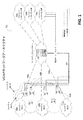
図1は、所定の実施形態に従った、仮想企業アクセスポイントネットワークアーキテクチャの態様を示す高水準のネットワーク図である。図1は、所定の実施形態に従って、クラウドコントローラ102、1つ以上のキャリアインターネット網104a〜c、1つ以上のキャリアWiFi105a〜c、及び複数のAP110a〜dを含む、VEAPネットワークアーキテクチャ100を示す。クラウドコントローラ102は、制御経路108a〜cを通して、キャリアWiFi105a〜cを制御する。クラウドコントローラ102は、データ経路107a〜dを通して複数のAP110a〜dと通信を行う。VEAPアーキテクチャは、外部ネットワーク(例えば、キャリアネットワーク)による、クラウドを介した効果的な垂直管理のために、既存のWiFiチップセットベンダの仮想AP(VAP)技術を活用する。所定の実施形態に従い、VAPの管理技術は、外部ネットワークとのネットワークインターフェースを提供する。さらに、VEAPアーキテクチャは、APインフラの管理を共有するために、複数のキャリアのためにマルチテナンシーサポートを提供する。ネットワーク現地オーナ(不動産及びAPハードウェア及びインフラのオーナ)は、現地を管理することに熟達している。したがって、所定の実施形態に従い、ネットワーク現地オーナ又はマネージャは、キャリア/SPに対して、WLANの企業グレード仮想AP、高品質ワイヤレスネットワークインフラサービス及びリモート集中管理を、企業グレードAPハードウェア及び関連したインフラを配備するわずかな価格で、提供することができる。
FIG. 1 is a high-level network diagram illustrating aspects of a virtual enterprise access point network architecture in accordance with certain embodiments. FIG. 1 illustrates a VEAP network architecture 100 that includes a
したがって、上記のVEAPアーキテクチャは、WiFiネットワークサービスの全てのパーティーに対して有益である。モバイルクライアントは、企業グレードワイヤレスネットワークサービスを享受する。現地オーナは、複数のキャリア/SPにAPインフラをリースすることにより、繰り返して収益を享受する。キャリア/SPは、高価な企業グレードAPハードウェアを購入して展開する必要無しに、高品質WLANを操業することが可能となる。したがって、キャリア/SPは、貯蓄を用いて、追加の価値を付加するサービスをモバイルクライアントに提供して部門収益を増大することが、可能となる。 Thus, the above VEAP architecture is beneficial for all parties of WiFi network services. Mobile clients enjoy enterprise-grade wireless network services. The local owner repeatedly enjoys profits by leasing AP infrastructure to multiple carriers / SPs. Carriers / SPs can operate high quality WLANs without having to purchase and deploy expensive enterprise grade AP hardware. Thus, carriers / SPs can use savings to provide mobile clients with services that add additional value to increase department revenue.
所定の実施形態に従い、アクセスポイント(AP)を仮想化することにより、アクセスポイントハードウェアリソースを、ネットワークリソースとは別々に管理できるようになるという利益がもたらされる。非限定的な例として、アクセスポイントハードウェアリソースは、無線通信スペースリソース、メモリ及びイーサネット(登録商標)インターフェースを含む。非限定的な例として、ネットワークリソースは、アクセスポイントネットワークブリッジ、インターネットプロトコル(IP)ネットワーク及びネットワークサーバを含む。所定の実施形態に従い、現地オーナ又はマネージャは、アクセスポイントハードウェア及びアクセスポイントハードウェアに関連するリソースを管理及び制御する。WLANオペレータは、ネットワークリソース及び仮想アクセスポイントを管理及び制御することが可能である。 In accordance with certain embodiments, virtualizing access points (APs) provides the benefit of allowing access point hardware resources to be managed separately from network resources. By way of non-limiting example, access point hardware resources include wireless communication space resources, memory, and Ethernet interfaces. By way of non-limiting example, network resources include access point network bridges, internet protocol (IP) networks, and network servers. In accordance with certain embodiments, the local owner or manager manages and controls access point hardware and resources associated with the access point hardware. A WLAN operator can manage and control network resources and virtual access points.
さらに、所定の実施形態に従い、APリソースを、仮想化することができる。非限定的な例として、WLANオペレータは、アクセスポイントに関連するメモリリソースの使用を、1つ以上の企業体(たとえば、1つ以上のウェブ取引企業)にリースすることができる。現地オーナ/マネージャが、キャリアネットワークでもあるという場合もある。そのような場合、1つ以上のウェブ取引企業は、現地オーナ/マネージャから、APメモリリソースのレンタルを受けることも可能である。非限定的な例として、所定の実施形態に従い、1つ以上のウェブ取引企業は、広告及びプロモーション活動、アプリケーションの保管、ビデオの保管、コンテンツの保管、クライアントトラフィックの分析、インターネットアクセスの制御、アプリケーションの配信及びコンテンツの配信のための、メモリリソースをリースすることができる。また、WLANオペレータは、ウェブ取引企業又は他の企業にリースしなかった自分のAPメモリリソースを、例えば広告及びプロモーション活動、アプリケーションの保管、ビデオの保管、コンテンツの保管、クライアントトラフィックの分析、インターネットアクセスの制御、アプリケーションの配信及びコンテンツの配信等の同様の目的のために用いることもできる。 Furthermore, AP resources can be virtualized according to certain embodiments. As a non-limiting example, a WLAN operator can lease the use of memory resources associated with an access point to one or more business entities (eg, one or more web trading companies). The local owner / manager may also be a carrier network. In such cases, one or more web trading companies can also rent AP memory resources from the local owner / manager. By way of non-limiting example, in accordance with certain embodiments, one or more web trading companies may provide advertising and promotional activities, application storage, video storage, content storage, client traffic analysis, Internet access control, applications Memory resources can be leased for distribution of content and content. WLAN operators can also use their AP memory resources that they did not lease to web trading companies or other companies, for example advertising and promotion activities, application storage, video storage, content storage, client traffic analysis, Internet access It can also be used for similar purposes such as control, application distribution and content distribution.
所定の実施形態に従い、クラウドコントローラは、マルチテナンシークラウドコントローラである。マルチテナンシークラウドコントローラは、別々のテナントコントローラ又は仮想コントローラを実行する複数のクラスタサーバを含む。所定の実施形態に従い、所定のAPが、クラスタサーバの中からAPの対応する仮想コントローラを特定することを援助するために、クラウドサイトコントローラマネージャ(SCM)が用いられる。例えば、所定のAPが「ワイヤレスアクセスポイントの制御及び供給」(CAPWAP)発見リクエストを送信するとき、SCMは、このCAPWAPリクエストをインターセプトする。このCAPWAPリクエストには、APのメディアアクセス制御アドレス(MACアドレス)及びAPに関連した固有のテナントアカウントのための証明書が含まれている。したがって、SCMはAPのMACアドレスを調べることができ、特定のAPに関連する固有テナントコントローラのアドレスを、そのAPに戻すことができる。APはその後、リクエストを各々のテナントコントローラに送信する試行錯誤方式ではなく、正しいテナントコントローラアドレスを用いて、CAPWAPプロトコルセッションを直接開始することができる。 In accordance with certain embodiments, the cloud controller is a multi-tenancy cloud controller. The multi-tenancy cloud controller includes a plurality of cluster servers that execute different tenant controllers or virtual controllers. In accordance with certain embodiments, a cloud site controller manager (SCM) is used to assist a given AP in identifying the corresponding virtual controller of the AP from among the cluster servers. For example, when a given AP sends a “Wireless Access Point Control and Provisioning” (CAPWAP) discovery request, the SCM intercepts the CAPWAP request. This CAPWAP request includes the AP's media access control address (MAC address) and a certificate for a unique tenant account associated with the AP. Thus, the SCM can look up the MAC address of the AP and return the unique tenant controller address associated with a particular AP to that AP. The AP can then directly initiate a CAPWAP protocol session using the correct tenant controller address, rather than a trial and error scheme that sends a request to each tenant controller.
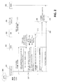
図2は、所定の実施形態に従った、発見の態様及びアクセスポイントに関連した登録手順を示す高水準参照図である。図2には、AP201、SCM202、データベース203、サーバクラスタ(又は、コントローラクラスタ)204、ネットワーク管理システム205及びDNSサーバ206が示される。SCM202とAP201が通信を行い(207を参照)、適切なテナントコントローラ212をAP201に(例えば、割り当てられたテナントアカウントID、APのデバイスID、APのプライベートIPアドレス及びAPの一般IPアドレスに基づいて)割り当てることにより、サーバクラスタ/コントローラクラスタ204内のAP201と、対応するテナントコントローラとの間で、データトランスポートレイヤセキュリティ(DTLS)セッション208を確立する。AP201は、DNSサーバ206からSCMのリストを見つけることができる。DTLSセッション208が確立されれば、APは、サーバクラスタ/コントローラクラスタ204内のAPの対応するテナントコントローラに、「結合」リクエスト209を送信することができる。結合が成功した場合は、テナントコントローラは、成功したAPの結合213を報告する。さらに、テナントコントローラ及び他のサーバクラスタが、情報210をデータベース203に報告することができる。その情報には、コントローラのロード、キャパシティ及び健全性を含めることができる。
FIG. 2 is a high-level reference diagram illustrating discovery aspects and registration procedures associated with access points, according to certain embodiments. 2 shows an
所定の実施形態の他の態様に従い、ここに説明するように、SCMは、VEAPネットワークアーキテクチャ下のAPディストリビューションに対する、複数のデータセンターロケーション間のコーディネータとしての機能も果たす。VEAPネットワークアーキテクチャ下では、データセンターロケーションは、現地オーナには、明白である。所定の実施形態に従い、各々のデータセンターは、VEAPネットワークアーキテクチャ下のいずれかのAPによりアクセス可能となっている。データセンターは、主サイト又はバックアップサイトとして、いずれかの現地オーナに対するサービスを提供する。所与のAPが現地オーナの施設に配備されれば、そのAPは、現地オーナによる機器構成を必要とすることなく、対応するデータセンターを自動的に決定して、そこへ接続することができる。したがって、データセンターは、APにより自動的に発見される必要がある。現地オーナの施設に配備されるAPが、適切なデータセンターとデータセンター内の対応するテナントコントローラとを結合することができるよう、SCMは、データセンター間及びデータセンター内部のコーディネータとなることができる。 In accordance with other aspects of certain embodiments, as described herein, the SCM also serves as a coordinator between multiple data center locations for AP distribution under the VEAP network architecture. Under the VEAP network architecture, the data center location is obvious to the local owner. In accordance with certain embodiments, each data center is accessible by any AP under the VEAP network architecture. The data center provides services to either local owner as the main site or backup site. If a given AP is deployed at a local owner's facility, that AP can automatically determine and connect to the corresponding data center without requiring equipment configuration by the local owner. . Therefore, the data center needs to be automatically discovered by the AP. The SCM can be a coordinator between data centers and within a data center so that an AP deployed at the local owner's facility can combine the appropriate data center with the corresponding tenant controller in the data center. .
SCMは、各々のデータセンターの第1の接点である。所定の実施形態に従い、SCMは、以下の特性を有する:1)SCMはそれぞれのデータセンターに配備され、SCMは第1の接点である。SCMは、APの発見リクエストを適切なデータセンター及びそのデータセンター内の正しいテナントコントローラにリダイレクトして、APとその対応するテナントコントローラとの間にセッションを確立するために、必要な知識を有している。2)SCMは、同じ地域のロケーションから異なるデータセンターロケーションに亘ってAPを広げる代わりに、正しいデータセンターロケーションとのAP接続を確定的にリダイレクトして統合することができる。3)SCMのリストは、標準DNSプロトコルを用いて、所与のいずれかのAPによって発見可能である。APは、DNS情報(DNS記録)を用いて、SCMのいずれかと交信することができる。したがって、APは、総当り戦方法でSCMのリストと交信して、登録のために適切なデータセンターのロケーションを見出すことが可能である。登録が成功すれば、APは、次の登録リクエストのブートアップ又はスタートアップのために、SCMのアドレスをキャッシュに格納することができる。 The SCM is the first contact of each data center. In accordance with certain embodiments, the SCM has the following characteristics: 1) The SCM is deployed at each data center, and the SCM is the first contact. The SCM has the necessary knowledge to redirect the AP discovery request to the appropriate data center and the correct tenant controller in that data center to establish a session between the AP and its corresponding tenant controller. ing. 2) The SCM can deterministically redirect and consolidate the AP connection with the correct data center location instead of extending the AP from the same regional location to different data center locations. 3) The list of SCMs can be found by any given AP using standard DNS protocol. The AP can communicate with any of the SCMs using DNS information (DNS recording). Thus, the AP can communicate with the list of SCMs in a brute force manner to find the appropriate data center location for registration. If registration is successful, the AP can store the address of the SCM in the cache for bootup or startup of the next registration request.
所定の実施形態に従い、クラウドベースのサイト間VPNネットワークを用いて、企業の支社に対して、従来のハードウェアVPNゲートウェイソリューションに関連した問題を、未然に防ぐ。クラウドベースのサイト間VPNネットワークを採用することにより、企業のそれぞれのオフィスサイトに、別々のVPNゲートウェイを設置することに関連した配備及び維持にかかるコスト上昇が、回避される。 In accordance with certain embodiments, cloud-based site-to-site VPN networks are used to obviate problems associated with traditional hardware VPN gateway solutions for corporate branches. By employing a cloud-based inter-site VPN network, the increased cost of deployment and maintenance associated with installing a separate VPN gateway at each office site of the enterprise is avoided.
所定の実施形態に従い、クラウドベースのサイト間VPNネットワークは、1 )ソフトウェア実行VPNゲートウェイ(ソフトVPNゲートウェイ)、及び、2)クラウドVPNコントローラ、を含む。リアルタイムトラフィックポリシングに対して、クラウドVPNコントローラからプッシュダウンされたポリシーを実行することができるゲートウェイを、ソフトVPNとして実行するように、企業の支社サイトに配備されるAPを設定することができる。クラウドVPNコントローラは、セントラルVPNポリシーマネジメント及びVPNトンネルネットワークを提供する。したがって、クラウドベースのサイト間VPNネットワークは、IT人員が、それぞれのサイトでハードウェアVPNゲートウェイをインストール又はこれにアクセスする必要無く、様々なサイト間での動的なVPNトラフィック経路ルーティングを、容易に改変/更新することを可能にするソフトウェアソリューションである。無線ネットワークのためのクラウドベースのソリューションを採用する企業は、企業の支社、小売店、POSサイト等を接続するために、クラウドベースのVPNソリューションを採用する可能性が高い。したがって、VPN市場は、数十億ドルの規模で運営されている。 In accordance with certain embodiments, a cloud-based site-to-site VPN network includes 1) a software execution VPN gateway (soft VPN gateway), and 2) a cloud VPN controller. For real-time traffic policing, the AP deployed at the corporate branch site can be configured to run as a soft VPN gateway that can execute policies pushed down from the cloud VPN controller. The cloud VPN controller provides central VPN policy management and VPN tunnel network. Thus, a cloud-based inter-site VPN network facilitates dynamic VPN traffic path routing between various sites without the need for IT personnel to install or access a hardware VPN gateway at each site. It is a software solution that can be modified / updated. Companies that adopt cloud-based solutions for wireless networks are likely to adopt cloud-based VPN solutions to connect company branches, retail stores, POS sites, and the like. Thus, the VPN market is operating on a multi-billion dollar scale.
図3は、所定の実施形態に従った、クラウドベースのサイト間VPN動的接続の態様を示す高水準ネットワーク図である。図3は、クラウドベースのVPNネットワークが、クラウド企業WLANコントローラ304a〜e、VPNサービスエンジン306a〜d、AP302a〜b及びセキュアトンネル305a〜bを含んでいることを示す。AP302a〜bは、ソフトVPNゲートウェイとして実行される。例えば、AP302aは、企業サイト301のソフトVPNゲートウェイとして実行される。AP302bは、企業サイト303のソフトVPNゲートウェイとして実行される。クラウド企業WLANコントローラ304c、304eは、セントラルVPNポリシーマネジメントを、AP302a、302bそれぞれに提供する。VPNサービスエンジン306a〜dは、企業サイト301、303の間のVPNトラフィック307に対して、セキュアトンネル305a〜bを動的に提供する。無線デバイス308aと308bとは、それらのそれぞれのAP302a、302b及びクラウド企業WLANコントローラ304c、304e、並びに、対応するセキュアトンネル305bを通して、通信を行う。
FIG. 3 is a high-level network diagram illustrating aspects of cloud-based site-to-site VPN dynamic connection according to certain embodiments. FIG. 3 shows that the cloud-based VPN network includes cloud
従来のハードウェアで実行される企業WLANコントローラに関しては、それぞれのハードウェアコントローラは、一群のAPに物理的に接続されている。したがって、APのグループは、バッチで設定及び管理が可能である。しかしながら、ここに説明されるWLAN用のクラウドベースのコントローラの場合、APは、コントローラに物理的に接続されていない。したがって、このような一組のAPは、従来の意味では、グループ化されないことになる。所定の現地オーナのサイトにありかつクラウドベースのWLANコントローラに関連する多数のAPに対して、バッチ設定を適用することは、困難である。所定の実施形態に従い、クラウドベースのWLANコントローラと関連するAPのバッチ設定を容易にするため、ワイヤレスモビリティドメインが作成される。所定の実施形態に従い、ワイヤレスモビリティドメインは、同じドメイン下で管理される一群のAPを定義する。所定のワイヤレスモビリティドメインのAPは、地理的に、相互及びAPが取り扱うワイヤレスクライアントの比較的近くに位置する。所定のワイヤレスモビリティドメインのAPは、同じWLAN設定及びポリシーを共有する。例えば、ワイヤレスモビリティドメインを用いて、企業本社からリモートに位置するそれぞれの企業支社等、特定のロケーションに配備されるAPの範囲を定義することができる。上記の例では、ワイヤレスモビリティドメインは企業支社ごとに、WLANマネジメントの設定が異なっていてもよい。したがって、企業のIT社員は、ワイヤレスモビリティドメインを用いることにより、それぞれの支社ごとに異なるWLANネットワークの設定及びポリシーを、容易かつ柔軟に適用することができる。 With respect to enterprise WLAN controllers running on conventional hardware, each hardware controller is physically connected to a group of APs. Therefore, a group of APs can be set and managed in a batch. However, in the case of the cloud-based controller for WLAN described here, the AP is not physically connected to the controller. Therefore, such a set of APs will not be grouped in the conventional sense. It is difficult to apply batch settings to a large number of APs that are at a given local owner's site and associated with a cloud-based WLAN controller. In accordance with certain embodiments, a wireless mobility domain is created to facilitate batch configuration of APs associated with cloud-based WLAN controllers. In accordance with certain embodiments, a wireless mobility domain defines a group of APs managed under the same domain. APs in a given wireless mobility domain are geographically located relatively close to each other and the wireless clients that the AP handles. APs in a given wireless mobility domain share the same WLAN settings and policies. For example, a wireless mobility domain can be used to define the scope of APs deployed at a particular location, such as each corporate branch located remotely from the corporate headquarters. In the above example, the wireless mobility domain may have different WLAN management settings for each company branch. Therefore, IT employees in a company can easily and flexibly apply different WLAN network settings and policies for each branch office by using a wireless mobility domain.
図4は、所定の実施形態に従って、ワイヤレスモビリティドメインを用いるAPのマネジメントの態様を示す高水準参照図である。図4は、本社ワイヤレスモビリティドメイン402及び対応する出張ワイヤレスモビリティドメイン403、404及び405を含む、ワイヤレスモビリティドメインネットワーク401を示す。ワイヤレスモビリティドメイン402、403、404及び405は、別々のWLAN設定及びポリシーを有していてもよい。
FIG. 4 is a high-level reference diagram illustrating aspects of AP management using a wireless mobility domain in accordance with certain embodiments. FIG. 4 shows a wireless
他の例として、大学キャンパスが、その学部の建物のそれぞれに、APを配備していると仮定する。大学は、1つのワイヤレスモビリティドメインを用いて、大学キャンパスの全てのAPを管理するか、又は、アセットトラッキングのため、又は、同じロケーション中の各学部又は各階に固有の、それとは異なるマネジメント目的のため、その学部の別々のワイヤレスモビリティドメインを用いるかの、選択権を有する。 As another example, assume that a university campus has an AP deployed in each of its departmental buildings. The university uses a single wireless mobility domain to manage all APs on the university campus, or for asset tracking, or for a different management purpose specific to each department or floor in the same location Therefore, they have the option of using the department's separate wireless mobility domain.
L3(レイヤ3)モビリティ又はローミングは、別々の会社サブネットをローミングで結ぶワイヤレスクライアントのために、継ぎ目のないワイヤレス接続性を提供する企業WLANの特徴である。例えば、会社が適切なWLANRFカバレージを有する場合は、L3モビリティは、ワイヤレスクライアント(スマートフォン、タブレット又はノートブック等)が、会社キャンパスの周囲でローミングを行いながら、VoIP及びビデオストリーミング等のリアルタイムアプリケーションをワイヤレスクライアント上で連続的に実行させることが、可能となる。 L3 (Layer 3) mobility or roaming is a feature of enterprise WLANs that provides seamless wireless connectivity for wireless clients that roam separate corporate subnets. For example, if a company has adequate WLANRF coverage, L3 Mobility can wirelessly connect real-time applications such as VoIP and video streaming while a wireless client (such as a smartphone, tablet or notebook) roams around the company campus. It is possible to run continuously on the client.
L3モビリティを達成するため、WLAN製品は、以下を実行する必要がある:1)一方のAPから他方へのワイヤレスクライアントの接続の高速ハンドオーバ;及び、2)別々のサブネットドメイン間で同じワイヤレスクライアントのIPアドレスを保持すること。 In order to achieve L3 mobility, WLAN products need to do the following: 1) fast handover of wireless client connections from one AP to the other; and 2) the same wireless client between different subnet domains Keep the IP address.
高速ハンドオーバは、ワイヤレスクライアント上でのリアルタイムアプリケーション稼動の中断又は切断を回避するために必要である。一方のAPから他方へ、ワイヤレスクライアント接続の高速ハンドオーバを実行するためには、ワイヤレスクライアントがローミングを行う新しいAPを再認証するために必要な時間は、40ms未満、又はアプリケーションによっては20ms未満、でなければならない。新しいAPの再認証は、新しいAPによる「再接続」ともいわれる。新しいAPを再認証するために必要な時間が20msによりも長い場合は、VoIPのようなリアルタイムアプリケーションに対して、ジッター又は切断が起こりうる。認証のために必要な時間は、ポートベースのアクセス制御AAAサーバ802.1Xによる良好なLAN環境では、約40ms〜80msである。 Fast handover is necessary to avoid interruption or disconnection of real-time application operation on the wireless client. In order to perform a fast handover of a wireless client connection from one AP to the other, the time required for the wireless client to re-authenticate a new AP to roam is less than 40 ms, or less than 20 ms depending on the application. There must be. Re-authentication of a new AP is also referred to as “reconnection” by the new AP. If the time required to re-authenticate a new AP is longer than 20 ms, jitter or disconnection can occur for real-time applications such as VoIP. The time required for authentication is about 40 ms to 80 ms in a good LAN environment with port-based access control AAA server 802.1X.
さらに、ワイヤレスクライアントが、別々のネットワークアドレスを有するサブネットに関連した新しいAPとのローミングを行う場合は、ワイヤレスクライアントは、サブネットのIPアドレスを取得する。ワイヤレスクライアントのIPアドレスが新しく取得されたIPアドレスに変更されれば、ワイヤレスクライアント上で実行しているアプリケーション(例えば、VoIP又はビデオストリーミング)は中断する。このような中断は、ビジネスコミュニケーションには不適当であり、ネットワークセキュリティポリシーの保持には不十分である。 Furthermore, if the wireless client roams with a new AP associated with a subnet having a separate network address, the wireless client obtains the IP address of the subnet. If the wireless client's IP address is changed to the newly acquired IP address, the application (eg, VoIP or video streaming) running on the wireless client is interrupted. Such interruptions are inappropriate for business communications and are insufficient to maintain network security policies.
適切なレイヤ3(L3)モビリティを提供するため、ワイヤレスクライアントがAPからAPへとローミングを行う際に、従来の企業WLANは、中央に位置するハードウェアコントローラを、唯一の認証者として利用することにより、ローミング中にそれぞれのAPで完全な再認証を実行する必要性が不要になる。セントラルハードウェアコントローラは、セントラルコントローラとワイヤレスクライアントのホームサブネットとの間のIPトンネルを容易にセットアップすることができ、この場合、ワイヤレスクライアントのIPアドレスはもともと割り当てられていたため、ワイヤレスクライアントが、そのもともとのIPアドレスを用い続けることができるのである。しかしながら、会社ネットワークに関連するコントローラが、セントラルにインストールされていないため、クラウドベースのコントローラを企業/会社ネットワークに用いる従来のハードウェアコントローラソリューションは、WLANに適用できない。クラウド(インターネット)では、予測不能で長期にわたるインターネット待ち時間が発生するので、クラウドベースのコントローラは、高速のハンドオーバを実行することができない。さらに、クラウドベースのコントローラが、会社WLANのセントラルロケーションにはなく、クラウドの中にあるため、クラウドベースのコントローラは、ワイヤレスクライアントのホームサブネットとクラウドベースのコントローラとの間で、IPトンネルをセットアップすることができない。また、インターネット接続がダウンしている場合は、クラウドベースのコントローラは、ワイヤレスクライアントのためのL3モビリティを保持することができない。 In order to provide proper Layer 3 (L3) mobility, when a wireless client roams from AP to AP, traditional enterprise WLANs use a centrally located hardware controller as the only authenticator This eliminates the need to perform full re-authentication at each AP during roaming. The central hardware controller can easily set up an IP tunnel between the central controller and the wireless client's home subnet, where the wireless client's IP address was originally assigned, so the wireless client It is possible to continue using the IP address. However, since the controller associated with the company network is not installed centrally, the conventional hardware controller solution that uses the cloud-based controller for the company / company network cannot be applied to the WLAN. In the cloud (Internet), there is an unpredictable and long internet latency, so cloud-based controllers cannot perform fast handovers. In addition, the cloud-based controller sets up an IP tunnel between the wireless client's home subnet and the cloud-based controller because the cloud-based controller is not in the central location of the company WLAN but in the cloud. I can't. Also, if the Internet connection is down, the cloud-based controller cannot maintain L3 mobility for wireless clients.
上記を考慮し、所定の実施形態に従い、以下の方法を用いて、クラウドベースのコントローラを用いるWLANでのL3モビリティをサポートする。1)クライアントローミング範囲を予測する、及び、2)ローミングアンカーAPを用いる。 In view of the above, according to certain embodiments, the following method is used to support L3 mobility in a WLAN using a cloud-based controller. 1) Predict the client roaming range, and 2) Use the roaming anchor AP.
所定の実施形態に従い、ワイヤレスクライアントによるローミング中に各APでワイヤレスクライアントの再認証/再接続処理を行う間の往復の数を低減することにより、高速ハンドオーバ機能を可能にすることに関連して、クライアントローミング範囲予測を用いる。最初のAPでの認証プロセスの一部を行っている間(ワイヤレスクライアントがローミングを行い始める前)に発生するマスターセッションキー(MSK)を、キャッシュに格納する又は別段に保存することにより、この往復の数を低減することは可能である。クラウドコントローラは、ワイヤレスクライアントがローミングを行う新しいAPに、MSKをコピーすることができる。したがって、ワイヤレスクライアントがその新しいAPにローミングを行う際に、新しいAPに求められるのは、バックエンドAAAサーバで完全な再認証プロセスを実行することではなく、ただトラフィックキー(TK)を再生して、再認証/再接続プロセスを完了するだけである。MSKを適切なAPにコピーするため、クラウドコントローラは、ワイヤレスクライアントがどのAPにローミングを行うかを事前に知っている必要がある。所定の実施形態に従い、各ワイヤレスクライアントのMSKを、会社ネットワークで全てのAPにコピーすることができる。この方法は、APが多数のキーに圧倒されてしまわないよう、少数のAPに有用である。他の具体例に従い、ワイヤレスクライアントのMSKは、ワイヤレスクライアントがローミングを行うことができると思われる一組のAPのみにコピーされ、そしてエージアウトタイマーを実行してこのAPからMSKを除去し、APがキーで渋滞することを回避する。説明すると、ワイヤレスクライアントがローミングを行うことができる近隣のAPの範囲(「ローミング範囲」)は、所定の実施形態によれば、確定的に特定される。 In connection with enabling fast handover functionality by reducing the number of round trips between wireless client re-authentication / reconnection processes at each AP during roaming by the wireless client, according to certain embodiments, Use client roaming range prediction. This round-trip by storing or otherwise storing the master session key (MSK) that occurs during part of the authentication process at the first AP (before the wireless client begins roaming) It is possible to reduce the number of The cloud controller can copy the MSK to the new AP where the wireless client roams. Thus, when a wireless client roams to its new AP, the new AP is not required to perform a full re-authentication process on the back-end AAA server, but just to replay the traffic key (TK). It only completes the re-authentication / reconnection process. In order to copy the MSK to the appropriate AP, the cloud controller needs to know in advance which AP the wireless client will roam to. In accordance with certain embodiments, each wireless client's MSK may be copied to all APs in the corporate network. This method is useful for a small number of APs so that the AP is not overwhelmed by a large number of keys. According to another embodiment, the wireless client's MSK is copied to only a set of APs that the wireless client is likely to be able to roam in, and an age-out timer is run to remove the MSK from this AP, Avoids traffic jams with keys. To illustrate, the range of neighboring APs (“roaming range”) that a wireless client can roam to is deterministically specified according to certain embodiments.
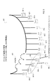
図5は、所定の実施形態に従ったワイヤレスクライアントのローミング範囲を予測する態様を示す高水準参照図である。図5は、APの「A」、「B」、「C」、「D」、「E」、「F」、「G」、「H」を示す。この実施形態では、いずれかの数のAPを含むことができるが、説明の容易性のため、APを8個だけ示すこととする。ワイヤレスクライアントが先ずAP「C」に関連するとき、ワイヤレスクライアントのローミング範囲は、緑色の破線502により示される近傍「A」、「B」、「D」、「E」を含むことが予測される。ワイヤレスクライアントが「E」へ移動すれば、ワイヤレスクライアントのローミング範囲は、赤色破線503により示される近傍「C」、「D」、「F」、「H」を含むと予測される。同様に、ワイヤレスクライアントが「F」へ移動すれば、ワイヤレスクライアントのローミング範囲は、青色破線504により示される、近傍「D」、「E」、「H」、「G」を含むと予測される、等である。したがって、MSKは、ワイヤレスクライアントのローミング範囲の中で限られたAPのセットにコピーされ得るのであり、オーナの現地又は企業ネットワーク中の全てのAPにコピーされるのではない。しかしながら、クラウドベースのコントローラが連絡可能でない場合、例えば会社のWAN又はインターネットがダウンしているような場合は、ワイヤレスクライアントの予測されたローミング範囲でAPにMSKをコピーするクラウドコントローラが存在しないことになる。所定の実施形態に従い、図9は、AP間通信の態様を示す高水準ネットワーク図である。図9は、会社WLAN900、AP901a〜m、ローミング範囲902、AP間通信903及びワイヤレスクライアント905を示す。所定の実施形態に従い、ワイヤレスクライアント905の予測されたローミング範囲902でAPにMSKをコピーするためのクラウドベースのコントローラが、連絡可能でない場合は、AP901a〜mは、バックホール有線ネットワークインターフェースによってAP間通信903を実行して、ワイヤレスクライアント905のローミング範囲でAP間に必要であるMSK及びその他の情報を交換することができる。802.1 1対応のAPは、ワイヤレスクライアント905が検出可能なビーコンフレームを、周期的にブロードキャストする。所定の実施形態に従い、APは、WLAN SSID及び802.11ベンダー固有IE(情報要素)を埋め込んだAP IPアドレスを、APのビーコンフレームに有する。この802.11ベンダー固有IEを有してブロードキャストされるビーコンフレームは、ローミング範囲内のAPにのみ受信されるだろう。ローミング範囲外にあるAPは、このブロードキャストされたビーコンフレームを受信しないだろう。したがって、ローミング範囲内のAPは、クラウドコントローラへの接続を行わずに、相互を検出することができ、また、相互とMSK情報を通信及び交換することができる。同様に、「ローミングアンカーAP」に関してここに説明する機能を提供するために、AP間通信を適用することができる。
FIG. 5 is a high-level reference diagram illustrating aspects of predicting roaming ranges for wireless clients according to certain embodiments. FIG. 5 shows “A”, “B”, “C”, “D”, “E”, “F”, “G”, “H” of the AP. In this embodiment, any number of APs can be included, but only eight APs are shown for ease of explanation. When a wireless client first associates with AP “C”, the wireless client's roaming range is expected to include the neighborhoods “A”, “B”, “D”, “E” indicated by the green dashed
所定の実施形態に従い、ローミングアンカーAPを用いることにより、ワイヤレスクライアントが同じサブネットの中でAPからAPまでローミングを行う際、又は、別々のサブネットにローミングを行う際に、ワイヤレスクライアントが同じIPアドレスを保つことが可能になる。ローミングアンカーAPは、ワイヤレスクライアントがサブネットからそのIPアドレスを当初取得したAPである。ローミングアンカーAPは、ローミングワイヤレスクライアントのためのアンカーポイントになる。クラウドコントローラは、ローミングアンカーAPの近傍APに、ローミングアンカーAPのIPアドレス情報を掲示することができる。例えば、ワイヤレスクライアントが近隣のAPにローミングを行えば、近隣のAP(例えば「X」)は、ローミングアンカーAPを有するIPトンネルを形成することができることになるので、ワイヤレスクライアントがそのもともとのIPアドレスを保つことができるようになる。ワイヤレスクライアントがさらに別のAP(例えば、「Y」)にローミングを行えば、新しいIPトンネルは、「Y」と、「X」ではなくローミングアンカーAPとの間で形成されるようになる。このIPトンネルを形成する方法により、APに対して過剰な数のIPトンネルを詰め込むことが、回避される。さらに、ローミングアンカーAPの情報が各APに保存されるため、所定のAPがクラウドコントローラへの接続を失った場合でも、L3モビリティ機能は、実行可能なままで保たれる。ワイヤレスクライアントがそのもともとのIPアドレスを取得した当初に、ローミングワイヤレスクライアントのアンカーAPを決定するためのクラウドコントローラが利用できない場合には、上記のAP間通信のためにブロードキャストされたビーコンフレームを使用して、アンカーAP情報を「ローミング範囲」のAPに提供することが可能となる。図6は、所定の実施形態に従った、サブネットアドレス情報601及びローミングアンカーAPアドレス602のサンプルデータフォーマットの表である。
In accordance with certain embodiments, by using a roaming anchor AP, when a wireless client roams from AP to AP in the same subnet, or when roaming to a different subnet, the wireless client has the same IP address. It becomes possible to keep. A roaming anchor AP is an AP from which a wireless client initially obtained its IP address from a subnet. The roaming anchor AP becomes an anchor point for roaming wireless clients. The cloud controller can post the IP address information of the roaming anchor AP on the neighboring AP of the roaming anchor AP. For example, if a wireless client roams to a neighboring AP, the neighboring AP (eg, “X”) will be able to form an IP tunnel with a roaming anchor AP, so that the wireless client has its original IP address. Will be able to keep. If the wireless client roams to yet another AP (eg, “Y”), a new IP tunnel will be formed between “Y” and the roaming anchor AP instead of “X”. This method of forming an IP tunnel avoids stuffing an excessive number of IP tunnels into the AP. Furthermore, since the information of the roaming anchor AP is stored in each AP, even when a predetermined AP loses connection to the cloud controller, the L3 mobility function is kept executable. If the cloud controller for determining the anchor AP of the roaming wireless client is not available when the wireless client acquires its original IP address, the beacon frame broadcast for the above-mentioned communication between APs is used. Thus, the anchor AP information can be provided to the AP in the “roaming range”. FIG. 6 is a table of sample data formats for
図7は、所定の実施形態に従った、クラウドベースのレイヤ3モビリティ制御の態様を示す高水準ネットワーク図である。図7は、クラウドコントローラ701、AP702a〜l、ローミングアンカーAP703、ワイヤレスクライアント706及びサブネット707、708及び709を示す。L3モビリティを制御するため、クラウドコントローラ701は、ワイヤレスクライアント706のローミング範囲内の「近傍AP」に、MSKをコピーする。ワイヤレスクライアント706のIPアドレスを保持するため、例えばワイヤレスクライアント706が、サブネット707から、サブネット708へサブネット709へとローミングを行う際に、ローミングアンカーAPと所定のAP702の間にIPトンネルが形成される。ここに記載される制御L3モビリティのための方法を、クラウドベースのコントローラを利用する大企業営業所ネットワークに用いることで、連続ワイヤレスVoIP通信及びネットワークセキュリティポリシーをモバイル機器に提供することが可能となる。
FIG. 7 is a high-level network diagram illustrating aspects of cloud-based
所定の実施形態に従い、ワイヤレスクライアントデバイスのローミング範囲内にある「近傍AP」は、クライアントデバイスに関連する無線通信信号強度指数(RSSI)情報をクラウドコントローラに送信する。さらに、所定のローミング範囲のアクセスポイント同士は、Wi−Fi又は有線のネットワークインターフェースによって相互間で情報を交換し合う。交換される情報には、アクセスポイントのローミング範囲内の各アクセスポイントのWLAN SSID(サービスセット識別名)情報及びIPアドレス情報が含まれる。 In accordance with certain embodiments, a “neighbor AP” that is within the roaming range of the wireless client device sends radio communication signal strength index (RSSI) information associated with the client device to the cloud controller. Furthermore, access points within a predetermined roaming range exchange information with each other via a Wi-Fi or wired network interface. The exchanged information includes WLAN SSID (service set identification name) information and IP address information of each access point within the roaming range of the access point.
ワイヤレスアクセスポイントの制御及び供給(「CAPWAP」)は、コントローラがワイヤレスアクセスポイントの収集を管理することを可能にする相互運用可能なプロトコルである。CAPWAPプロトコルは、制御チャネル用のUDPポート5246及びデータチャネル用のポート5247の使用を含んでいる。CAPWAP標準は、設定マネジメント及びデバイスマネジメントを、APの方にプッシュできるようにする。CAPWAPプロトコルは、いくつかの段階を含む。1)発見、2)結合、3)、設定、4)ファームウェアアップデート、及び、5)マネジメント。UDPブロードキャストは会社ネットワークに限定されインターネットに転送されないため、既存のCAPWAP発見プロトコルは、インターネット対しては有効でない。さらに、社内ネットワーク内のファイアウォールが、インターネットへのUDPユニキャストをブロックし得る。CAPWAP発見プロトコルは、専用の予め設定されたハードウェアコントローラでのみ有効なだけある。ここに記載されるように、CAPWAP発見プロトコルはマルチテナントクラウド構造で実行される仮想コントローラを発見することができない。 Wireless access point control and provisioning (“CAPWAP”) is an interoperable protocol that allows the controller to manage the collection of wireless access points. The CAPWAP protocol includes the use of a UDP port 5246 for the control channel and a port 5247 for the data channel. The CAPWAP standard allows configuration management and device management to be pushed towards the AP. The CAPWAP protocol includes several stages. 1) discovery, 2) binding, 3), configuration, 4) firmware update, and 5) management. The existing CAPWAP discovery protocol is not valid for the Internet because UDP broadcasts are limited to the corporate network and are not forwarded to the Internet. In addition, a firewall within the corporate network may block UDP unicast to the Internet. The CAPWAP discovery protocol is only valid with a dedicated preconfigured hardware controller. As described herein, the CAPWAP discovery protocol cannot discover virtual controllers that run in a multi-tenant cloud structure.
所定の実施形態に従い、ここに記載されるマルチテナントクラウド構造に使用するため、従来のCAPWAPを、標準HTTPS(ハイパーテキストトランスファープロトコルセキュア)プロトコルを用いるクラウドコントローラCAPWAP発見プロトコルを用いて置換する。クラウドコントローラCAPWAP発見プロトコルは、社内ネットワークに関連する潜在的ファイアウォールの問題を解決し得る。クラウドコントローラCAPWAP発見プロトコルは、対応する仮想コントローラを先ず発見して、適切な輸送プロトコルをネゴシエートする。例えば、輸送プロトコルは、社内ネットワークファイアウォール条件により、もともとのUDPプロトコル又はHTTP(ハイパーテキストトランスファープロトコル)プロトコルとすることができる。HTTPセッションがクラウドリソースに関してスケーリング問題を引き起こし得るため、UDPは、クラウドベースコントローラのための好ましい輸送手段である。クラウドコントローラCAPWAP発見プロトコルは、クラウドベースのコントローラでのリソースの使用を最適化する。クラウドコントローラCAPWAP発見プロトコルは、CAPWAPプロトコルを、会社のプライベートなLAN又はVPNネットワーク内に制限するのに代えて、外部のインターネット網に延長することに対する最初のステップを確立する。したがって、クラウドベースのコントローラに連携したクラウドベースのCAPWAP発見プロトコルは、内部の企業ネットワーク又はVPNの使用に限定するのではなく、例えばマルチプロトコル標識スイッチング仮想専用ネットワーク(MPLSVPN)等の広域ネットワークにわたるインターネットソリューションを提供する。 In accordance with certain embodiments, the conventional CAPWAP is replaced with a cloud controller CAPWAP discovery protocol that uses the standard HTTPS (Hypertext Transfer Protocol Secure) protocol for use in the multi-tenant cloud structure described herein. The cloud controller CAPWAP discovery protocol can solve potential firewall problems associated with corporate networks. The cloud controller CAPWAP discovery protocol first discovers the corresponding virtual controller and negotiates an appropriate transport protocol. For example, the transport protocol can be the original UDP protocol or HTTP (Hypertext Transfer Protocol) protocol, depending on in-house network firewall conditions. UDP is a preferred vehicle for cloud-based controllers because HTTP sessions can cause scaling problems with cloud resources. The cloud controller CAPWAP discovery protocol optimizes resource usage on a cloud-based controller. The cloud controller CAPWAP discovery protocol establishes the first step for extending the CAPWAP protocol to an external Internet network instead of confining it within the company's private LAN or VPN network. Thus, the cloud-based CAPWAP discovery protocol in conjunction with a cloud-based controller is not limited to the use of an internal corporate network or VPN, but is an Internet solution that spans a wide area network, such as a multiprotocol beacon switching virtual private network (MPLSVPN) I will provide a.
発見段階の結果によっては、会社ファイアウォールがインターネットへのUDPプロトコルをブロックする際に、クラウドベースのコントローラと結合して通信するために、クラウドベースのCAPWAP発見プロトコルは、APに対するHTTPプロトコルの使用をネゴシエートすることができる。所定の実施形態に従い、レガシーCAPWAPUDPプロトコルに対して領域互換性があるため、クラウドベースのCAPWAPUDPプロトコルは、HTTPトンネルに供給される。AP及びクラウドベースのコントローラの両方は任意に、HTTPプロトコルでCAPWAPUDPパケットをカプセル化することができ、また、カプセル開放を行うことができる。HTTPプロトコルは、UDP輸送手段とは完全に別々なTCP輸送手段プロトコルである。各UDPパケットは、受信により命令されるパケット境界の指示を含む。受信者側でのUDPメッセージの読込み操作により、もともと送信されたメッセージ全体の長さがわかる。対照的に、TCPプロトコルデータは、バイトストリームとして読み出され、信号メッセージ境界には、特徴的な指示は伝送されない。さらに、TCPプロトコルデータは、バイトストリームとして読み出されるため、元々のUDPメッセージパケットの途中で、受信者側に読取り中断が発生する可能性は、非常に高い。所定の実施形態に従い、HTTPプロトコルにおけるUDPパケット境界指示を含む専用のライトウェイトプロトコルが用いられる。さらに、このライトウェイトプロトコルは、受信者側のUDPメッセージの読取りが、元々のUDPパケットの途中で切断されないことを確実にする方法で、プロトコルを保持する。このプロトコルは、会社LAN環境からインターネット環境(クラウド環境)へのCAPWAPプロトコル移動を完了させる一方、元々の標準CAPWAPUDPプロトコルとの互換性を保持して、従来の企業APや従来の企業コントローラでの相互運用性を確保する。 Depending on the outcome of the discovery phase, the cloud-based CAPWAP discovery protocol negotiates the use of the HTTP protocol for the AP to communicate with the cloud-based controller when the corporate firewall blocks the UDP protocol to the Internet. can do. In accordance with certain embodiments, the cloud-based CAPWAPUDP protocol is supplied to the HTTP tunnel because it is domain compatible with the legacy CAPWAPUDP protocol. Both the AP and cloud-based controller can optionally encapsulate and decapsulate CAPWAPUDP packets with the HTTP protocol. The HTTP protocol is a TCP transport protocol that is completely separate from the UDP transport. Each UDP packet includes an indication of the packet boundary that is commanded upon reception. By reading the UDP message on the receiver side, the total length of the originally transmitted message can be known. In contrast, TCP protocol data is read as a byte stream and no characteristic indication is transmitted at the signal message boundary. Furthermore, since the TCP protocol data is read out as a byte stream, there is a very high possibility that reading will be interrupted on the receiver side in the middle of the original UDP message packet. In accordance with certain embodiments, a dedicated lightweight protocol that includes a UDP packet boundary indication in the HTTP protocol is used. Furthermore, this lightweight protocol retains the protocol in a way that ensures that the recipient's reading of the UDP message is not cut off in the middle of the original UDP packet. This protocol completes the CAPWAP protocol movement from the corporate LAN environment to the Internet environment (cloud environment), while maintaining compatibility with the original standard CAPWAPUDP protocol, and interoperability with traditional corporate APs and traditional corporate controllers. Ensure operability.
所定の実施形態に従い、APとこれに対応するクラウドコントローラとの間のファイアウォールをAPが検出した時に、APは、データグラムトランスポートレイヤセキュリティ(DTLS)プロトコル上のCAPWAPから、HTTPプロトコル上のCAPWAPへと切り替える情報を有している。換言すれば、発見が終了した後、ファイアウォールがAPとクラウドコントローラとの間にない場合に、デフォルトとして、所定のAPは、DTLSプロトコル上のCAPWAPを用いて、UDPのデータ輸送手段の安全な通信に関連したクラウドコントローラと、接続及び通信を行う。しかしながら、APとクラウドコントローラとの間にファイアウォールがある場合は、APは、ファイアウォールを検出するのに十分情報を有しており、HTTP又はHTTPプロトコルを用いて、クラウドコントローラと、接続及び通信を行うだろう。 In accordance with certain embodiments, when the AP detects a firewall between the AP and its corresponding cloud controller, the AP can transition from a CAPWAP over Datagram Transport Layer Security (DTLS) protocol to a CAPWAP over HTTP protocol. And have information to switch. In other words, after discovery is complete, if a firewall is not between the AP and the cloud controller, by default, a given AP uses CAPWAP over the DTLS protocol to securely communicate UDP data transport means. Connect and communicate with the cloud controller related to However, if there is a firewall between the AP and the cloud controller, the AP has enough information to detect the firewall and uses the HTTP or HTTP protocol to connect and communicate with the cloud controller. right.
高速ネットワークリンクからの全てのHTTP URL/ヘッダ等のパケットトレースを捕捉して、さらに後処理のためにハードディスクにこのトレースを保存することは、高コストのハードウェア・プラットフォームが必要となり、又は、OSネットワーキングスタックを最適化してメモリコピーの数を削減することが必要となる。しかしながら、最適化されたネットワーキングスタックを有する一般的なオペレーティングシステム、又は、例えばリテール版WiFi AP又は事業グレードライトAP等の低コストプラットホームは、開発されていない。したがって、APパフォーマンスとのトレードオフなしで、高速パケットトレースを収集することは、困難である。 Capturing packet traces such as all HTTP URLs / headers from high-speed network links and saving this trace to hard disk for further processing requires a costly hardware platform or OS There is a need to optimize the networking stack to reduce the number of memory copies. However, common operating systems with optimized networking stacks or low cost platforms such as retail WiFi APs or business grade light APs have not been developed. Therefore, it is difficult to collect high speed packet traces without a tradeoff with AP performance.
一般的なオペレーティングシステムでは、取得されたネットワークパケットをハードディスクに保存する経路は、以下を含む:1)ネットワークプロセッサーは、取得されたパケットに対してフィルタリングを行うために、ディープパケットインスペクションを実行する;2)ネットワークプロセッサはパケットを取得して、そのパケットをDMA(ダイレクトメモリアクセス)にコピーし、CPUによりOSを起動させ、ディスクファイルへの読み書きをするよう、ユーザスペースソフトウェアアプリケーションをスケジューリングする;3)OSファイルシステムオペレーションはコストが高く、特にデータをディスクファイルへ書き込むために大量のCPUタイムを消費する。例えば、Linux(登録商標) EXT3ファイルシステムでは、データオペレーションのタイプにもよるが、CPU使用率は、27%〜99%である。さらに、ディスクファイルへの高速ネットワークリンクを用いて、パケットを取得して保存する際は、CPU使用率は著しく上昇し、APパフォーマンスに影響を及ぼしうることになる。 In a typical operating system, the path to store acquired network packets on the hard disk includes: 1) The network processor performs deep packet inspection to filter the acquired packets; 2) The network processor gets the packet, copies the packet to DMA (Direct Memory Access), starts the OS by the CPU, and schedules the user space software application to read and write to the disk file; 3) OS file system operations are expensive and consume a large amount of CPU time, especially for writing data to disk files. For example, in the Linux (registered trademark) EXT3 file system, depending on the type of data operation, the CPU usage rate is 27% to 99%. In addition, when using high-speed network links to disk files to acquire and store packets, CPU utilization increases significantly, which can affect AP performance.
所定の実施形態に従い、パケットを保存するための、APネットワークプロセッサからAPのハードディスクまでの高速経路が、用いられる。所定の実施形態に従い、APネットワークプロセッサがパケットを取得してDMAに関するデータを保存した後、APのOSを起動して、APディスクファイルにデータを読み書きするよう、ユーザスペースソフトウェアアプリケーションをリスケジュールする代わりに、APカーネルスペースドライバを呼び出して、DMAからAPのハードディスクへと直接データを伝送し、したがって、APのOSファイルシステムを完全にバイパスするよう、APのOSは設定される。カーネルスペースドライバのCPU使用率は、比較的低い。しかしながら、ディスク上に保存されるデータを、一般的なOSファイルシステムが処理することができるフォーマットとすることができない点が、トレードオフになる。したがって、所定の実施形態に従い、APのOSファイルシステムによってディスクファイルからデータを読み出す代わりに、カーネルドライバAPIを用いて、ユーザスペース読取り書込みアプリケーションのためにパケットを保存しているディスクから、直接データを読み出す。このプロセスは再び、APのOSファイルシステムオペレーションをバイパスする。この方法によれば、取得された各パケットトレースに対しての、往復のファイルシステムI/Oプロセスが排除される。この方法では、ごくわずかなCPUタイムしか用いずに、ネットワークプロセッサからハードディスクへと、ほぼ直接にハードウェアをコピーする。 In accordance with certain embodiments, a fast path from the AP network processor to the AP hard disk is used to store the packets. Instead of rescheduling the user space software application to start the AP's OS and read / write data to / from the AP disk file after the AP network processor obtains the packet and saves the DMA related data in accordance with certain embodiments In addition, the AP OS is configured to call the AP kernel space driver to transfer data directly from the DMA to the AP hard disk, and thus completely bypass the AP OS file system. The CPU usage rate of the kernel space driver is relatively low. However, the trade-off is that the data stored on the disk cannot be in a format that can be processed by a general OS file system. Thus, according to certain embodiments, instead of reading data from a disk file by the AP's OS file system, the kernel driver API is used to retrieve data directly from the disk storing the packet for a user space read / write application. read out. This process again bypasses the AP's OS file system operation. This method eliminates the round trip file system I / O process for each acquired packet trace. In this method, the hardware is copied almost directly from the network processor to the hard disk using very little CPU time.
図8は、所定の実施形態に従い、アクセスポイント(AP)において経路を格納する高速ネットワークデータのデザインの態様を示す高水準ネットワーク図である。図8は、APWiFiドライバ801、APネットワークドライバ802、APディスクドライバ803、APOSファイルシステム805、読取り書込みアプリケーション806及びAPOSカーネル808を示す。データ保存のための高速経路を、赤色(破線矢印)で示し、それにより、ネットワークドライバ802は、OSファイルシステム805をバイパスし、読取り書込みアプリケーション806を用いて、データをAPハードディスクへ書き込む。
FIG. 8 is a high-level network diagram illustrating aspects of the design of high-speed network data that stores routes at an access point (AP) in accordance with certain embodiments. FIG. 8 shows an
所定の実施形態に従い、ワイヤレスネットワークを管理する方法は、以下を含む:現地で複数のワイヤレスアクセスポイントハードウェアユニットを配備すること;ここで、少なくともワイヤレスアクセスポイントハードウェアユニットのサブセットのそれぞれは、ワイヤレスアクセスポイントメモリ構成要素を含み;現地で、複数の仮想ワイヤレスアクセスポイントを、複数のワイヤレスアクセスポイントハードウェアユニットの対応するワイヤレスアクセスポイントハードウェアユニットに関連させること;仮想ワイヤレスアクセスポイントの複数のグループを形成すること;第1の複数の企業体のそれぞれに、仮想ワイヤレスアクセスポイントの1つ以上のグループを管理及び制御できるようにすること;及び、仮想ワイヤレスアクセスポイントの第1の複数のグループの少なくとも1つのサブセットの各グループを、1つ以上のワイヤレスアクセスポイントメモリ構成要素に関連した対応するメモリアロケーションに関連させること。所定の実施形態に従い、この方法は、第1の複数の企業体のそれぞれの企業体に対して、第2の複数の企業体の他の企業体に、その対応するメモリアロケーションをサブリースないし転貸できるようにすることをさらに備え、また、第1又は第2の複数の企業体のそれぞれの企業体に対して、以下の1つ以上のために、その対応するメモリアロケーションを用いることができるようにすることを、さらに備える。広告及びプロモーション活動、アプリケーション保管、ビデオ保管、及びコンテンツ保管、並びにさらに、ロケーションベースの広告及び/又は時系列式の広告を用いることを含む。また、この方法は、第1又は第2の複数の企業体のそれぞれの企業体に対して、クライアントトラフィック分析、インターネットアクセス制御、アプリケーション配信及びコンテンツ配信、の1つ以上のために、その対応するメモリアロケーションを用いることができるようにすることを、さらに備える。 In accordance with certain embodiments, a method for managing a wireless network includes: deploying a plurality of wireless access point hardware units on-site; wherein each of at least a subset of wireless access point hardware units is wireless Including an access point memory component; associating a plurality of virtual wireless access points locally with a corresponding wireless access point hardware unit of a plurality of wireless access point hardware units; Allowing each of the first plurality of business entities to manage and control one or more groups of virtual wireless access points; and virtual wireless access The first of each group of at least a subset of the plurality of groups of points, be associated with memory allocation for the corresponding associated with one or more wireless access points memory component. In accordance with certain embodiments, the method can sublease or sublease its corresponding memory allocation to another business entity of the second plurality of business entities for each business entity of the first plurality of business entities. And for each business entity of the first or second plurality of business entities, the corresponding memory allocation can be used for one or more of the following: To further comprise. Including advertising and promotional activities, application storage, video storage, and content storage, as well as using location-based advertising and / or time series advertising. The method also corresponds to each of the first or second plurality of business entities for one or more of client traffic analysis, Internet access control, application distribution and content distribution. It further comprises enabling the use of memory allocation.
所定の実施形態によると、ワイヤレスネットワークは、以下を備える:現地で配備される複数のワイヤレスアクセスポイントハードウェアユニット、ここで、少なくともワイヤレスアクセスポイントハードウェアユニットのサブセットのそれぞれは、ワイヤレスアクセスポイントを含み;メモリ要素、ここで、複数の仮想ワイヤレスアクセスポイントは、現地の複数のワイヤレスアクセスポイントハードウェアユニットの対応するワイヤレスアクセスポイントハードウェアユニットに関連し;仮想ワイヤレスアクセスポイントの複数のグループが、形成され;複数の企業体のそれぞれが、仮想ワイヤレスアクセスポイントの1つ以上のグループを管理及び制御できるようにし;及び、仮想ワイヤレスアクセスポイントの複数のグループの少なくとも1つのサブセットの各グループは、1つ以上のワイヤレスアクセスポイントメモリ構成要素に関連した対応するメモリアロケーションに関連する。所定の実施形態に従い、複数の企業体のそれぞれの企業体は、以下に記載する1つ以上のために、対応するメモリアロケーションを用いることが可能である:広告及びプロモーション活動、アプリケーションの保管、ビデオの保管及びコンテンツの保管、及び、ロケーションベースの広告及び/又は時系列式の広告。さらに、複数の企業体のそれぞれの企業体は、以下の1つ以上のために、その対応するメモリアロケーションを他の企業体に転貸することができるようになる:広告及びプロモーション活動、アプリケーションの保管、ビデオの保管及びコンテンツの保管。また、複数の企業体のそれぞれの企業体は、以下の1つ以上のために、対応するメモリアロケーションを用いることができるようになる:クライアントトラフィック分析、インターネットアクセス制御、アプリケーション配信及びコンテンツ配信。 According to certain embodiments, the wireless network comprises: a plurality of locally deployed wireless access point hardware units, wherein each of at least a subset of the wireless access point hardware units includes a wireless access point. A memory element, where a plurality of virtual wireless access points are associated with a corresponding wireless access point hardware unit of a plurality of local wireless access point hardware units; a plurality of groups of virtual wireless access points are formed; Allowing each of a plurality of business entities to manage and control one or more groups of virtual wireless access points; and a small number of groups of virtual wireless access points In each group of one of the subsets is associated with the memory allocation for the corresponding associated with one or more wireless access points memory component. In accordance with certain embodiments, each business entity of the plurality of business entities can use corresponding memory allocations for one or more of the following: advertising and promotional activities, application storage, video Storage and content storage, and location-based and / or time-series advertising. In addition, each business entity of multiple business entities will be able to sublease its corresponding memory allocation to other business entities for one or more of the following: advertising and promotion activities, application storage , Video storage and content storage. Also, each business entity of the plurality of business entities can use corresponding memory allocation for one or more of the following: client traffic analysis, Internet access control, application delivery and content delivery.
所定の実施形態に従い、ワイヤレスアクセス方法は、ワイヤレスアクセスポイントにより送信される発見リクエストを受信すること、ワイヤレスアクセスポイントに関連するメディアアクセス制御アドレス情報を、発見リクエストから取得すること、ワイヤレスアクセスポイントがテナントコントローラにあらかじめ割り当てられていたならば、ワイヤレスアクセスポイントに関連するテナントアカウント情報を、発見リクエストから取得すること、及び、テナントアカウント情報に関連するテナントコントローラのIPアドレス及びポート情報を、ワイヤレスアクセスポイントに送信すること、を備える。この方法はさらに、ワイヤレスアクセスポイントがテナントアカウントIDをすでに有しないならば、テナントアカウントIDをワイヤレスアクセスポイントに割り当てること、及び、ワイヤレスアクセスポイントを、新しく割り当てられたテナントアカウントID、ワイヤレスアクセスポイントのデバイスID、ワイヤレスアクセスポイントのプライベートIPアドレス、及びワイヤレスアクセスポイントのパブリックIPアドレスに基づき、適切なテナントコントローラに割り当てること、を備える。この方法はさらに、テナントコントローラに関連した複数のサーバクラスタから、テナントコントローラに関する情報を受信することを備える。さらに、この方法は、地域のロケーションに関連するワイヤレスアクセスポイントを、同じデータセンターの対応するテナントコントローラに割り当てることにより、ワイヤレスアクセスポイント接続を統合することをさらに備える。また、この方法はさらに、テナントアカウント情報が、固有サイトコントローラマネージャに対応するテナントコントローラに関連するならば、ワイヤレスアクセスポイントを、固有サイトコントローラマネージャに向けることを、備える。 In accordance with certain embodiments, a wireless access method can receive a discovery request transmitted by a wireless access point, obtain media access control address information associated with the wireless access point from the discovery request, and the wireless access point can be a tenant. If pre-assigned to the controller, the tenant account information related to the wireless access point is acquired from the discovery request, and the IP address and port information of the tenant controller related to the tenant account information are stored in the wireless access point. Transmitting. The method further includes assigning the tenant account ID to the wireless access point if the wireless access point does not already have a tenant account ID, and assigning the wireless access point to the newly assigned tenant account ID, the device of the wireless access point. Assigning to an appropriate tenant controller based on the ID, the wireless access point's private IP address, and the wireless access point's public IP address. The method further comprises receiving information regarding the tenant controller from a plurality of server clusters associated with the tenant controller. Further, the method further comprises integrating wireless access point connections by assigning wireless access points associated with regional locations to corresponding tenant controllers in the same data center. The method further comprises directing the wireless access point to the unique site controller manager if the tenant account information is associated with a tenant controller corresponding to the unique site controller manager.
所定の実施形態に従い、ワイヤレスアクセス方法は、ワイヤレスアクセスポイントにより、発見リクエストを、サイトコントローラマネージャに送信すること、ここでテナントアカウントがワイヤレスアクセスポイントにあらかじめ割り当てられるならば、発見リクエストは、ワイヤレスアクセスポイントに関連するメディアアクセス制御アドレス情報及びテナントアカウント情報を含む、テナントアカウント情報に関連するテナントコントローラのIPアドレス及びポート情報を、ワイヤレスアクセスポイントにより受信すること、及び、ワイヤレスアクセスポイントにより、テナントコントローラとのデータトランスポートレイヤセキュリティセッションを確立すること、を備える。この方法はさらに、ワイヤレスアクセスポイントがテナントアカウントIDをすでに有しないならば、ワイヤレスアクセスポイントによりテナントアカウントIDを受信することを、備える。この方法はさらに、ワイヤレスアクセスポイントにより、複数のサイトコントローラマネージャのそれぞれに関連するDNS情報を、発見すること、及び、発見されたDNS情報を用いて、複数のサイトコントローラマネージャのいずれか1つと交信すること、を備える。 According to certain embodiments, the wireless access method sends a discovery request to a site controller manager by a wireless access point, where if the tenant account is pre-assigned to the wireless access point, the discovery request Receiving the IP address and port information of the tenant controller related to the tenant account information, including the media access control address information and the tenant account information related to the wireless access point, and Establishing a data transport layer security session. The method further comprises receiving a tenant account ID by the wireless access point if the wireless access point does not already have a tenant account ID. The method further includes discovering DNS information associated with each of the plurality of site controller managers with the wireless access point and communicating with any one of the plurality of site controller managers using the discovered DNS information. Providing.
所定の実施形態によると、ワイヤレスネットワークは、複数のサイトコントローラマネージャを備え、少なくとも複数のサイトコントローラマネージャのサブセットの各々のサイトコントローラマネージャは、少なくとも1つの対応するデータセンターと関連し、ここで、複数のサイトコントローラマネージャの少なくとも1人のサイトコントローラマネージャは、ワイヤレスアクセスポイントにより送信される発見リクエストを受信し、ワイヤレスアクセスポイントに関連するメディアアクセス制御アドレス情報を、発見リクエストから取得し、ワイヤレスアクセスポイントがテナントコントローラにあらかじめ割り当てられていたならば、ワイヤレスアクセスポイントに関連するテナントアカウント情報を、発見リクエストから取得し、及び、テナントアカウント情報に関連するテナントコントローラのIPアドレス及びポート情報を、ワイヤレスアクセスポイントに送信する。所定の実施形態に従い、ワイヤレスアクセスポイントがテナントアカウントIDをすでに有しないならば、複数のサイトコントローラマネージャの少なくとも1人のサイトコントローラマネージャが、テナントアカウントIDをワイヤレスアクセスポイントに割り当て、ワイヤレスアクセスポイントを、新しく割り当てられたテナントアカウントID、ワイヤレスアクセスポイントのデバイスID、ワイヤレスアクセスポイントのプライベートIPアドレス、及びワイヤレスアクセスポイントのパブリックIPアドレスに基づき、適切なテナントコントローラに割り当てる。さらに、複数のサイトコントローラマネージャの少なくとも1つのサイトコントローラマネージャは、テナントコントローラに関連する複数のサーバクラスタから、テナントコントローラに関する情報を受信する。また、複数のサイトコントローラマネージャの少なくとも1つのサイトコントローラマネージャは、地域のロケーションに関連するワイヤレスアクセスポイントを同じデータセンターの対応するテナントコントローラに割り当てることにより、ワイヤレスアクセスポイント接続を統合する。所定の実施形態に従い、テナントアカウント情報が、固有サイトコントローラマネージャに対応するテナントコントローラに関連するならば、複数のサイトコントローラマネージャの少なくとも1つのサイトコントローラマネージャは、ワイヤレスアクセスポイントを固有サイトコントローラマネージャに向ける。 According to certain embodiments, the wireless network comprises a plurality of site controller managers, each site controller manager of each of the at least a subset of site controller managers being associated with at least one corresponding data center, wherein At least one of the site controller managers receives a discovery request sent by the wireless access point, obtains media access control address information associated with the wireless access point from the discovery request, and the wireless access point If it was pre-assigned to the tenant controller, get tenant account information related to the wireless access point from the discovery request, Beauty, the IP address and port information of the tenant controller associated with the tenant account information, and transmits it to the wireless access point. According to certain embodiments, if the wireless access point does not already have a tenant account ID, at least one site controller manager of the plurality of site controller managers assigns the tenant account ID to the wireless access point, Assign to the appropriate tenant controller based on the newly assigned tenant account ID, device ID of the wireless access point, private IP address of the wireless access point, and public IP address of the wireless access point. Further, at least one site controller manager of the plurality of site controller managers receives information regarding the tenant controller from a plurality of server clusters associated with the tenant controller. Also, at least one site controller manager of the plurality of site controller managers integrates wireless access point connections by assigning wireless access points associated with regional locations to corresponding tenant controllers in the same data center. According to certain embodiments, if the tenant account information is associated with a tenant controller corresponding to a unique site controller manager, at least one site controller manager of the plurality of site controller managers directs the wireless access point to the unique site controller manager. .
所定の実施形態に従い、ワイヤレスネットワークは、複数のワイヤレスアクセスポイントを備え、複数のワイヤレスアクセスポイントの少なくとも1つのワイヤレスアクセスポイントは、発見リクエストをサイトコントローラマネージャに送信し、ここでこの発見リクエストは、テナントアカウントが少なくとも1つのワイヤレスアクセスポイントにあらかじめ割り当てられるならば、少なくとも1つのワイヤレスアクセスポイントに関連するメディアアクセス制御アドレス情報及びテナントアカウント情報を含み、テナントアカウント情報に関連するテナントコントローラのIPアドレス及びポート情報を受信し、テナントコントローラとのデータトランスポートレイヤセキュリティセッションを確立する。さらに、少なくとも1つのワイヤレスアクセスポイントがテナントアカウントIDをすでに有しないならば、少なくとも1つのワイヤレスアクセスポイントはテナントアカウントIDを受信する。また、少なくとも1つのワイヤレスアクセスポイントは、複数のサイトコントローラマネージャのそれぞれに関連するDNS情報を発見し、発見されたDNS情報を用いて、複数のサイトコントローラマネージャのいずれか1つと交信する。 According to certain embodiments, the wireless network comprises a plurality of wireless access points, and at least one wireless access point of the plurality of wireless access points sends a discovery request to the site controller manager, where the discovery request is a tenant If the account is pre-assigned to at least one wireless access point, it includes media access control address information and tenant account information associated with at least one wireless access point, and the tenant controller IP address and port information associated with the tenant account information And establish a data transport layer security session with the tenant controller. Further, if at least one wireless access point does not already have a tenant account ID, the at least one wireless access point receives the tenant account ID. In addition, the at least one wireless access point discovers DNS information associated with each of the plurality of site controller managers, and communicates with any one of the plurality of site controller managers using the discovered DNS information.
所定の実施形態に従い、ワイヤレスアクセス方法は、第1のワイヤレスアクセスポイントが、第1の仮想専用ネットワークゲートウェイとして動作できるように、第1の仮想専用ネットワークサイトで、第1のワイヤレスアクセスポイントを設計すること、第1のワイヤレスアクセスポイントを、第1のWLANクラウドコントローラ及び対応する第1の仮想専用ネットワークサービスエンジンに関連させること、第2のワイヤレスアクセスポイントが第2の仮想専用ネットワークゲートウェイとして動作できるように、第2の仮想専用ネットワークサイトで、第2のワイヤレスアクセスポイントを設計すること、第2のワイヤレスアクセスポイントを、第2のWLANクラウドコントローラ及び対応する第2の仮想専用ネットワークサービスエンジンに関連させること、及び、第1の仮想専用ネットワークサービスエンジンと第2の仮想専用ネットワークサービスエンジンとの間に、セキュアトンネルを動的に提供することにより、第1の仮想専用ネットワークサイトの第1のワイヤレスクライアントデバイスが、第2の仮想専用ネットワークサイトの第2のワイヤレスクライアントデバイスと、通信できるようにすること、を備える。この方法は、第1及び第2のワイヤレスアクセスポイントによる実行のために、第1及び第2のワイヤレスアクセスポイントに、一組の仮想専用ネットワークトラフィックポリシーを提供することを、さらに備える。さらに、この方法は、第1及び第2のワイヤレスアクセスポイントで、仮想専用ネットワークゲートウェイソフトウェア(ソフトVPNゲートウェイ)を実行すること、及び、対応するWLANクラウドコントローラにより管理される対応するルーティングテーブルを変更することにより、仮想専用ネットワークサイト間のトラフィック経路ルーティングを変更すること、を備える。さらに、第1及び第2のワイヤレスアクセスポイントは、仮想ワイヤレスアクセスポイントである。 In accordance with certain embodiments, a wireless access method designs a first wireless access point at a first virtual dedicated network site such that the first wireless access point can operate as a first virtual dedicated network gateway. Associating the first wireless access point with the first WLAN cloud controller and the corresponding first virtual private network service engine, so that the second wireless access point can operate as a second virtual private network gateway. Designing a second wireless access point at a second virtual private network site, the second wireless access point comprising a second WLAN cloud controller and a corresponding second virtual private network service; By associating with the engine and dynamically providing a secure tunnel between the first virtual private network service engine and the second virtual private network service engine. Enabling one wireless client device to communicate with a second wireless client device of a second virtual private network site. The method further comprises providing a set of virtual dedicated network traffic policies to the first and second wireless access points for execution by the first and second wireless access points. In addition, the method executes virtual private network gateway software (soft VPN gateway) at the first and second wireless access points and changes the corresponding routing table managed by the corresponding WLAN cloud controller. Changing the traffic route routing between the virtual dedicated network sites. Further, the first and second wireless access points are virtual wireless access points.
所定の実施形態に従い、仮想専用ネットワークは、以下を含む:第1の仮想専用ネットワークサイトの第1のワイヤレスアクセスポイント、ここで、第1のワイヤレスアクセスポイントは、第1のワイヤレスアクセスポイントが、第1の仮想専用ネットワークゲートウェイとして動作できるように設計され、かつ、第1のWLANクラウドコントローラ及び対応する第1の仮想専用ネットワークサービスエンジンに関連し;第2の仮想専用ネットワークサイトの第2のワイヤレスアクセスポイント、ここで、第2のワイヤレスアクセスポイントは、第2のワイヤレスアクセスポイントが、第2の仮想専用ネットワークゲートウェイとして動作できるように設計され、かつ、第2のワイヤレスアクセスポイントは、第2のWLANクラウドコントローラ及び対応する第2の仮想専用ネットワークサービスエンジンに関連し;ここで、セキュアトンネルは、第1の仮想専用ネットワークサービスエンジンと第2の仮想専用ネットワークサービスエンジンとの間で動的に提供され、第1の仮想専用ネットワークサイトの第1のワイヤレスクライアントデバイスが、第2の仮想専用ネットワークサイトの第2のワイヤレスクライアントデバイスと通信できるようになる。この仮想専用ネットワークは、第1及び第2のワイヤレスアクセスポイントによる実行のために、第1及び第2のワイヤレスアクセスポイントに提供される一組の仮想専用ネットワークトラフィックポリシーを、さらに備える。さらに、仮想専用ネットワークは、第1及び第2のワイヤレスアクセスポイントで実行される仮想専用ネットワークゲートウェイソフトウェア(ソフトVPNゲートウェイ)を備える。また、第1及び第2のワイヤレスアクセスポイントは、仮想ワイヤレスアクセスポイントである。さらに、対応するWLANクラウドコントローラにより管理される対応するルーティングテーブルを変更することにより、仮想専用ネットワークサイトの間のトラフィック経路ルーティングを変更することができる。 In accordance with certain embodiments, the virtual private network includes: a first wireless access point of a first virtual private network site, where the first wireless access point is the first wireless access point, Designed to operate as one virtual private network gateway and associated with a first WLAN cloud controller and a corresponding first virtual private network service engine; second wireless access of a second virtual private network site Point, where the second wireless access point is designed such that the second wireless access point can operate as a second virtual private network gateway, and the second wireless access point is a second WLAN Cloud computer A secure tunnel is dynamically provided between the first virtual dedicated network service engine and the second virtual dedicated network service engine; and The first wireless client device at the first virtual private network site can communicate with the second wireless client device at the second virtual private network site. The virtual private network further comprises a set of virtual private network traffic policies provided to the first and second wireless access points for execution by the first and second wireless access points. In addition, the virtual private network comprises virtual private network gateway software (soft VPN gateway) running on the first and second wireless access points. The first and second wireless access points are virtual wireless access points. Furthermore, the traffic route routing between virtual private network sites can be changed by changing the corresponding routing table managed by the corresponding WLAN cloud controller.
所定の実施形態に従い、ワイヤレスアクセスポイント(CAPWAP)の制御及び供給のためのワイヤレスアクセス方法は、以下を含む:クラウドベースのCAPWAP発見プロトコルの一部として、HTTPSプロトコル(ハイパーテキストトランスファーセキュアプロトコル)を用いて、ワイヤレスアクセスポイントが、HTTP接続に対応するクラウドベースの仮想コントローラの位置情報を発見することができるようにすること、ここで、対応するクラウドベースの仮想コントローラは、ワイヤレスアクセスポイントを管理する;ワイヤレスアクセスポイントと、輸送手段プロトコルをネゴシエートすること;及び、ワイヤレスアクセスポイントと対応するクラウドベースの仮想コントローラとの間のユーザーデータグラムプロトコル(UDP)通信が、ファイアウォールによりブロックされるならば、ワイヤレスアクセスポイントと対応するクラウドベースの仮想コントローラとの間のHTTPSトンネルを、UDP通信に用いること。さらに、この方法は、HTTPSプロトコル中にUDPパケット境界情報を含めることをさらに備える。この方法は、UDPメッセージの受信者によるUDPメッセージの連続的な読取りを保持することをさらに備える。所定の実施形態に従い、マルチテナントクラウドベースコントローラに関連するワイヤレスアクセスポイント(CAPWAP)を制御及び供給するためのワイヤレス方法は、アクセスポイントと対応するクラウドベースのコントローラとの間の通信のためのデフォルトプロトコルとして、データグラムトランスポートレイヤセキュリティ(DTLS)プロトコル上のCAPWAPを用いること、及び、アクセスポイントと対応するクラウドベースのコントローラとの間でファイアウォールが検出された場合に、アクセスポイントと対応するクラウドベースのコントローラとの間の通信のために、ハイパーテキストトランスファープロトコル(HTTP)上又はハイパーテキストトランスファープロトコルセキュア(HTTPs)上のCAPWAPを用いること、を備える。 In accordance with certain embodiments, a wireless access method for control and provisioning of a wireless access point (CAPWAP) includes: using HTTPS protocol (Hypertext Transfer Secure Protocol) as part of a cloud-based CAPWAP discovery protocol Enabling the wireless access point to discover the location information of the cloud-based virtual controller corresponding to the HTTP connection, where the corresponding cloud-based virtual controller manages the wireless access point; Negotiating a transport protocol with the wireless access point; and a user datagram protocol between the wireless access point and the corresponding cloud-based virtual controller (UDP) communication, if it is blocked by a firewall, the HTTPS tunnel between the cloud-based virtual controller and the corresponding wireless access point, using the UDP communication. Further, the method further comprises including UDP packet boundary information in the HTTPS protocol. The method further comprises maintaining a continuous reading of the UDP message by the recipient of the UDP message. In accordance with certain embodiments, a wireless method for controlling and serving a wireless access point (CAPWAP) associated with a multi-tenant cloud-based controller is a default protocol for communication between an access point and a corresponding cloud-based controller Using the CAPWAP over Datagram Transport Layer Security (DTLS) protocol, and if a firewall is detected between the access point and the corresponding cloud-based controller, the cloud-based CAPW over Hypertext Transfer Protocol (HTTP) or Hypertext Transfer Protocol Secure (HTTPs) for communication with the controller The use of P, comprises a.
所定の実施形態に従い、ワイヤレスアクセス方法は、ワイヤレスアクセスポイントのオペレーティングシステムのファイルシステムをバイパスするため、及び、ワイヤレスアクセスポイントのダイレクトメモリアクセス(DMA)からワイヤレスアクセスポイントのハードディスクにネットワークパケット化情報を直接書き込むために、ワイヤレスアクセスポイントのカーネルスペースドライバが、ワイヤレスアクセスポイントのハードディスクドライバと直接通信できるようにするために、ワイヤレスアクセスポイントのオペレーティングシステムを設計することを備える。この方法はさらに、ワイヤレスアクセスポイントのハードディスクからネットワークパケット化情報を直接読み出すために、カーネルスペースドライバが、ワイヤレスアクセスポイントのハードディスクドライバと直接通信できるようにすることを備える。所定の実施形態に従い、ワイヤレスアクセスポイントは、ワイヤレスアクセスポイントのオペレーティングシステム、ワイヤレスアクセスポイントのカーネルスペースドライバ、及び、ワイヤレスアクセスポイントのハードディスクドライバ、を備え、ワイヤレスアクセスポイントのオペレーティングシステムのファイルシステムをバイパスするように、及び、所定の実施形態に従って、ワイヤレスアクセスポイントのダイレクトメモリアクセス(DMA)からワイヤレスアクセスポイントのハードディスクにネットワークパケット化情報を直接書き込むために、ワイヤレスアクセスポイントのカーネルスペースドライバが、ワイヤレスアクセスポイントのハードディスクドライバと直接通信できるようにするよう、ワイヤレスアクセスポイントのオペレーティングシステムは設計される。 In accordance with certain embodiments, a wireless access method bypasses a wireless access point operating system file system and directs network packetization information directly from the wireless access point's direct memory access (DMA) to the wireless access point's hard disk. For writing, the wireless access point kernel space driver comprises designing a wireless access point operating system to allow direct communication with the wireless access point hard disk driver. The method further comprises enabling the kernel space driver to communicate directly with the wireless access point hard disk driver to read network packetization information directly from the wireless access point hard disk. In accordance with certain embodiments, a wireless access point comprises a wireless access point operating system, a wireless access point kernel space driver, and a wireless access point hard disk driver, and bypasses the wireless access point operating system file system. In order to write network packetization information directly from the wireless access point direct memory access (DMA) to the wireless access point hard disk, the wireless access point kernel space driver Wireless access point so that it can communicate directly with Door operating system is designed.
所定の実施形態に従い、ワイヤレスの方法は、クラウドベースのコントローラにより管理されるアクセスポイントの複数のグループを、各グループのアクセスポイントとの設定類似点に基づき、形成すること、アクセスポイントの複数のグループの各グループを、それぞれのワイヤレスモビリティドメインに指定すること、及び、各ワイヤレスモビリティドメインに固有のWLANの設定及びポリシーを用いて、各ワイヤレスモビリティドメインのアクセスポイントを管理すること、を備える。この方法では、一組の地理ロケーション基準に基づき、アクセスポイントの複数のグループが形成される。さらに、一連の論理的基準に基づき、アクセスポイントの複数のグループが形成される。さらに、所定の実施形態に従い、この方法は、ワイヤレスモビリティドメインをアセットトラッキングに用いることをさらに備える。 In accordance with certain embodiments, a wireless method includes forming a plurality of groups of access points managed by a cloud-based controller based on configuration similarities with each group of access points, the plurality of groups of access points Each access point of each wireless mobility domain using a WLAN configuration and policy specific to each wireless mobility domain. In this method, multiple groups of access points are formed based on a set of geographic location criteria. In addition, a plurality of groups of access points are formed based on a set of logical criteria. Moreover, according to certain embodiments, the method further comprises using the wireless mobility domain for asset tracking.
所定の実施形態に従い、ワイヤレスネットワークは、各グループのアクセスポイントとの設定類似点に基づくアクセスポイントの複数のグループを備え、アクセスポイントの複数のグループの各グループは、それぞれのワイヤレスモビリティドメインとして指定され、アクセスポイントは、クラウドベースのコントローラにより、それぞれのワイヤレスモビリティドメインに固有のWLANの設定及びポリシーを用いて、管理されている。さらに、アクセスポイントの複数のグループは、一連の地理ロケーション基準に基づく。さらに、アクセスポイントの複数のグループは、一連の論理的基準に基づく。また、所定の実施形態によれば、ワイヤレスモビリティドメインは、アセットをトラッキングすることが可能である。さらに、所定の実施形態に従い、カーネルスペースドライバは、ワイヤレスアクセスポイントのハードディスクからネットワークパケット化情報を直接読み出すために、ワイヤレスアクセスポイントのハードディスクドライバと直接通信できるようになる。 In accordance with certain embodiments, the wireless network comprises a plurality of groups of access points based on configuration similarities with each group of access points, each group of the plurality of groups of access points being designated as a respective wireless mobility domain. The access point is managed by the cloud-based controller using WLAN settings and policies specific to each wireless mobility domain. Further, the multiple groups of access points are based on a set of geographic location criteria. Furthermore, the multiple groups of access points are based on a set of logical criteria. Also, according to certain embodiments, the wireless mobility domain can track assets. Further, in accordance with certain embodiments, the kernel space driver can communicate directly with the wireless access point hard disk driver to read network packetization information directly from the wireless access point hard disk.
前記の記載は、説明の目的のために、特定の実施形態を参照して記載してきた。しかしながら、上記の例示的な議論は、網羅的であること又は開示される厳密な形態に本発明を限定することを、意図するものではない。多くの変形及び変更は、上記の教示を考慮して可能である。本発明及びその実際の応用の原理を最も適切に説明するために、実施形態を選択して説明し、それによって、当業者は、想定される特定の使用に適するよう様々に変形することにより、本発明及び様々な実施形態を最も適切に利用することができる。 The foregoing description has been described with reference to specific embodiments for illustrative purposes. However, the illustrative discussions above are not intended to be exhaustive or to limit the invention to the precise forms disclosed. Many variations and modifications are possible in view of the above teachings. In order to best describe the principles of the invention and its actual application, the embodiments have been selected and described, thereby allowing those skilled in the art to make various modifications to suit the particular use envisioned. The present invention and various embodiments can be best utilized.
Claims (13)
前記物理ロケーションで、複数の仮想ワイヤレスアクセスポイントを、前記複数のワイヤレスアクセスポイントハードウェアユニットの対応するワイヤレスアクセスポイントハードウェアユニットに関連させること、
前記複数の仮想ワイヤレスアクセスポイントの仮想ワイヤレスアクセスポイントの第1のサブセットを、第1のWLANネットワークオペレータにリースすること、及び、
前記複数の仮想ワイヤレスアクセスポイントの仮想ワイヤレスアクセスポイントの第2のサブセットを、第2のWLANネットワークオペレータにリースすること、
を備える方法。 Deploying multiple wireless access point hardware units in a physical location;
Associating a plurality of virtual wireless access points at the physical location with a corresponding wireless access point hardware unit of the plurality of wireless access point hardware units;
Leasing a first subset of virtual wireless access points of the plurality of virtual wireless access points to a first WLAN network operator; and
Leasing a second subset of virtual wireless access points of the plurality of virtual wireless access points to a second WLAN network operator;
A method comprising:
現地で配備される複数のワイヤレスアクセスポイントハードウェアユニットを備え、
前記複数のワイヤレスアクセスポイントハードウェアユニットのワイヤレスアクセスポイントハードウェアユニットは、複数の仮想ワイヤレスアクセスポイントを提供し、
前記複数のワイヤレスアクセスポイントハードウェアユニットは、現地のオペレータにより所有され、
前記複数の仮想ワイヤレスアクセスポイントの仮想ワイヤレスアクセスポイントの第1のサブセットは、第1のWLANプロバイダにより所有され、
前記複数の仮想ワイヤレスアクセスポイントの仮想ワイヤレスアクセスポイントの第2のサブセットは、第2のWLANプロバイダにより所有される、
ワイヤレスネットワーク。 A wireless network,
With multiple wireless access point hardware units deployed locally,
A wireless access point hardware unit of the plurality of wireless access point hardware units provides a plurality of virtual wireless access points;
The plurality of wireless access point hardware units are owned by a local operator,
A first subset of virtual wireless access points of the plurality of virtual wireless access points is owned by a first WLAN provider;
A second subset of virtual wireless access points of the plurality of virtual wireless access points is owned by a second WLAN provider;
Wireless network.
ローミングワイヤレスクライアントデバイスに関連するマスターセッションキー(MSK)情報を保存すること、
ここで、前記マスターセッションキー(MSK)情報は、前記ローミングワイヤレスクライアントデバイスのためのアンカーアクセスポイントで、前記ローミングワイヤレスクライアントデバイスに関連する認証を行う間に発生し、
前記アンカーアクセスポイントから、前記ローミングワイヤレスクライアントデバイスがローミングを行うアクセスポイントの第1のローミング範囲を予測すること、
前記マスターセッションキー(MSK)情報を、前記アクセスポイントの前記第1のローミング範囲の少なくとも第1のサブセットに、コピーすること、及び、
前記ローミングワイヤレスクライアントデバイスが現在ローミングを行っている現在のアクセスポイントと、前記アンカーアクセスポイントとの間に、インターネットプロトコルトンネルを形成できるようにすること、
を備え、
前記インターネットプロトコルトンネルは、前記ワイヤレスクライアントデバイスが、前記アンカーアクセスポイントに関連するその元々のIPアドレスを保持することを可能にする、方法。 A method for supporting L3 mobility when using a cloud-based controller,
Storing master session key (MSK) information associated with the roaming wireless client device;
Wherein the master session key (MSK) information is generated during an authentication associated with the roaming wireless client device at an anchor access point for the roaming wireless client device;
Predicting from the anchor access point a first roaming range of an access point to which the roaming wireless client device roams;
Copying the master session key (MSK) information to at least a first subset of the first roaming range of the access point; and
Enabling the roaming wireless client device to form an internet protocol tunnel between the current access point currently roaming and the anchor access point;
With
The internet protocol tunnel allows the wireless client device to retain its original IP address associated with the anchor access point.
Applications Claiming Priority (3)
| Application Number | Priority Date | Filing Date | Title |
|---|---|---|---|
| US201361821852P | 2013-05-10 | 2013-05-10 | |
| US61/821,852 | 2013-05-10 | ||
| PCT/US2014/037613 WO2014183107A2 (en) | 2013-05-10 | 2014-05-11 | Virtual enterprise access point control and management |
Publications (2)
| Publication Number | Publication Date |
|---|---|
| JP2016526319A true JP2016526319A (en) | 2016-09-01 |
| JP2016526319A5 JP2016526319A5 (en) | 2017-06-22 |
Family
ID=51853272
Family Applications (1)
| Application Number | Title | Priority Date | Filing Date |
|---|---|---|---|
| JP2016513139A Pending JP2016526319A (en) | 2013-05-10 | 2014-05-11 | Control and management of virtual enterprise access points |
Country Status (6)
| Country | Link |
|---|---|
| US (8) | US20140334336A1 (en) |
| EP (1) | EP2995041A4 (en) |
| JP (1) | JP2016526319A (en) |
| CN (1) | CN104144205A (en) |
| TW (1) | TWI578836B (en) |
| WO (1) | WO2014183107A2 (en) |
Cited By (1)
| Publication number | Priority date | Publication date | Assignee | Title |
|---|---|---|---|---|
| WO2019240158A1 (en) * | 2018-06-13 | 2019-12-19 | 日本電気株式会社 | Communication system and communication method |
Families Citing this family (57)
| Publication number | Priority date | Publication date | Assignee | Title |
|---|---|---|---|---|
| US10805331B2 (en) | 2010-09-24 | 2020-10-13 | BitSight Technologies, Inc. | Information technology security assessment system |
| US8817707B2 (en) * | 2012-07-20 | 2014-08-26 | Intel Corporation | Mechanisms for roaming between 3GPP operators and WLAN service providers |
| US9438615B2 (en) | 2013-09-09 | 2016-09-06 | BitSight Technologies, Inc. | Security risk management |
| US9686127B2 (en) | 2014-09-16 | 2017-06-20 | CloudGenix, Inc. | Methods and systems for application performance profiles, link capacity measurement, traffic quarantine and performance controls |
| US20160094387A1 (en) * | 2014-09-30 | 2016-03-31 | Ruckus Wireless, Inc. | Discovery of cloud-based access-point controllers |
| CN105871663B (en) | 2015-01-19 | 2019-04-05 | 环旭电子股份有限公司 | Wireless ethernet network control method and wireless ethernet network system |
| TWI558255B (en) * | 2015-01-19 | 2016-11-11 | 環鴻科技股份有限公司 | Wireless ethernet network controlling method and wireless ethernet network system |
| US9882774B2 (en) | 2015-02-02 | 2018-01-30 | Eero Inc. | Systems and methods for intuitive home networking |
| US10374946B2 (en) * | 2015-03-16 | 2019-08-06 | Dell Products L.P. | Centralized wireless network management system |
| US11272361B2 (en) | 2015-03-30 | 2022-03-08 | Arris Enterprises Llc | Zero-touch onboarding in a network |
| US20180300190A1 (en) | 2015-06-24 | 2018-10-18 | Relay2, Inc. | Mobile application service engine (mase) |
| US20160381597A1 (en) * | 2015-06-24 | 2016-12-29 | Relay2, Inc. | WiFi Airtime Allocation |
| US10390217B2 (en) | 2016-12-27 | 2019-08-20 | Neutrino8, Inc. | Wireless configuration of wireless distribution system (WDS) Wi-Fi range extenders using non-Wi-Fi-wireless communication channels |
| US11019560B2 (en) | 2015-09-16 | 2021-05-25 | Neutrino8, Inc. | Selective cloud-based SSID (service set identifier) steering for allowing different levels of access for wireless network friends when onboarding on Wi-Fi networks |
| US10420155B2 (en) * | 2016-03-18 | 2019-09-17 | Plume Design, Inc. | Distributed Wi-Fi setup systems and methods |
| US10374814B2 (en) * | 2016-07-26 | 2019-08-06 | Extreme Networks, Inc. | Access point cloud controller auto-discovery |
| JP6737955B2 (en) | 2016-09-27 | 2020-08-12 | エーナイン・ドット・コム インコーポレイテッドA9.com, Inc. | How to share network settings |
| US10225789B2 (en) | 2016-10-31 | 2019-03-05 | Cisco Technology, Inc. | Virtual access point (VAP) formation |
| US10367623B2 (en) | 2016-10-31 | 2019-07-30 | Cisco Technology, Inc. | Data traffic management in virtual access point (VAP) enabled networks |
| US10757647B2 (en) * | 2016-10-31 | 2020-08-25 | Cisco Technology, Inc. | Optimized channel selection for virtual access point (VAP) enabled networks |
| US10638287B2 (en) | 2016-10-31 | 2020-04-28 | Cisco Technology, Inc. | Transparent roaming in virtual access point (VAP) enabled networks |
| US20180139171A1 (en) * | 2016-11-17 | 2018-05-17 | Armada Logistics, Inc. | Systems, apparatuses and methods for tracking assets using domain name system signaling |
| US10205724B2 (en) * | 2016-12-27 | 2019-02-12 | Neutrino8, Inc. | Cloud-based onboarding of cloud-controlled Wi-Fi network devices |
| WO2018204885A1 (en) * | 2017-05-04 | 2018-11-08 | Deepak Das | Mobility functionality for a cloud-based access system |
| JP2018195974A (en) * | 2017-05-17 | 2018-12-06 | アライドテレシスホールディングス株式会社 | Wireless LAN access point and encryption key sharing method |
| US10425380B2 (en) | 2017-06-22 | 2019-09-24 | BitSight Technologies, Inc. | Methods for mapping IP addresses and domains to organizations using user activity data |
| US10524267B2 (en) * | 2018-01-11 | 2019-12-31 | Cisco Technology, Inc. | Traffic and mobility aware virtual access points |
| US10893418B2 (en) | 2018-03-08 | 2021-01-12 | Hewlett Packard Enterprise Development Lp | AP deployment in a network comprising a centralized system and a distributed system |
| US10257219B1 (en) | 2018-03-12 | 2019-04-09 | BitSight Technologies, Inc. | Correlated risk in cybersecurity |
| US10812520B2 (en) | 2018-04-17 | 2020-10-20 | BitSight Technologies, Inc. | Systems and methods for external detection of misconfigured systems |
| US11272442B2 (en) | 2018-09-07 | 2022-03-08 | Samsung Electronics Co., Ltd | Method and system for dynamic access point selection in coordinated access point group |
| US11200323B2 (en) | 2018-10-17 | 2021-12-14 | BitSight Technologies, Inc. | Systems and methods for forecasting cybersecurity ratings based on event-rate scenarios |
| US11175970B2 (en) * | 2018-10-24 | 2021-11-16 | Sap Se | Messaging in a multi-cloud computing environment |
| US10521583B1 (en) | 2018-10-25 | 2019-12-31 | BitSight Technologies, Inc. | Systems and methods for remote detection of software through browser webinjects |
| WO2020092245A1 (en) * | 2018-10-29 | 2020-05-07 | Zorday IP, LLC | Network-enabled electronic cigarette |
| CN109743745B (en) * | 2019-02-19 | 2021-01-22 | 北京三快在线科技有限公司 | Mobile network access type identification method and device, electronic equipment and storage medium |
| US11979821B2 (en) | 2019-04-26 | 2024-05-07 | Hewlett Packard Enterprise Development Lp | Multitenant network device management |
| US10726136B1 (en) | 2019-07-17 | 2020-07-28 | BitSight Technologies, Inc. | Systems and methods for generating security improvement plans for entities |
| US10887851B1 (en) * | 2019-07-24 | 2021-01-05 | Cisco Technology, Inc. | Dynamic transmission power in wireless mesh networks using supervised and semi-supervised learning |
| US11956265B2 (en) | 2019-08-23 | 2024-04-09 | BitSight Technologies, Inc. | Systems and methods for inferring entity relationships via network communications of users or user devices |
| US10848382B1 (en) | 2019-09-26 | 2020-11-24 | BitSight Technologies, Inc. | Systems and methods for network asset discovery and association thereof with entities |
| US11032244B2 (en) | 2019-09-30 | 2021-06-08 | BitSight Technologies, Inc. | Systems and methods for determining asset importance in security risk management |
| US10791140B1 (en) | 2020-01-29 | 2020-09-29 | BitSight Technologies, Inc. | Systems and methods for assessing cybersecurity state of entities based on computer network characterization |
| US10893067B1 (en) | 2020-01-31 | 2021-01-12 | BitSight Technologies, Inc. | Systems and methods for rapidly generating security ratings |
| US10764298B1 (en) | 2020-02-26 | 2020-09-01 | BitSight Technologies, Inc. | Systems and methods for improving a security profile of an entity based on peer security profiles |
| EP3905639A1 (en) * | 2020-04-29 | 2021-11-03 | Rohde & Schwarz GmbH & Co. KG | Communication system and method of controlling air traffic of an airspace |
| US11023585B1 (en) | 2020-05-27 | 2021-06-01 | BitSight Technologies, Inc. | Systems and methods for managing cybersecurity alerts |
| US11122073B1 (en) | 2020-12-11 | 2021-09-14 | BitSight Technologies, Inc. | Systems and methods for cybersecurity risk mitigation and management |
| US12079347B2 (en) | 2021-03-31 | 2024-09-03 | BitSight Technologies, Inc. | Systems and methods for assessing cybersecurity risk in a work from home environment |
| US11665087B2 (en) | 2021-09-15 | 2023-05-30 | International Business Machines Corporation | Transparent service-aware multi-path networking with a feature of multiplexing |
| US12081985B2 (en) * | 2021-10-27 | 2024-09-03 | Hewlett Packard Enterprise Development Lp | Broadcast of intrusion detection information |
| US12096252B2 (en) * | 2021-11-23 | 2024-09-17 | Hewlett Packard Enterprise Development Lp | Mitigation of radio frequency (RF) outages on a wireless network |
| CN114490467B (en) * | 2022-01-26 | 2024-03-19 | 中国电子科技集团公司第五十四研究所 | Message processing DMA system and method of multi-core network processor |
| WO2023172764A2 (en) * | 2022-03-11 | 2023-09-14 | Mobulusnet Ltd. | Systems, and methods for secure remote multi-user lan access |
| US20230308870A1 (en) * | 2022-03-24 | 2023-09-28 | Charter Communications Operating, Llc | Dynamic key caching for fast roaming in secured wireless networks |
| US11863534B1 (en) * | 2023-02-03 | 2024-01-02 | Dice Corporation | Scalable router interface initiation |
| US11895091B1 (en) | 2023-02-03 | 2024-02-06 | Dice Corporation | Scalable router interface communication paths |
Citations (1)
| Publication number | Priority date | Publication date | Assignee | Title |
|---|---|---|---|---|
| US20020022483A1 (en) * | 2000-04-18 | 2002-02-21 | Wayport, Inc. | Distributed network communication system which allows multiple wireless service providers to share a common network infrastructure |
Family Cites Families (37)
| Publication number | Priority date | Publication date | Assignee | Title |
|---|---|---|---|---|
| US5805809A (en) | 1995-04-26 | 1998-09-08 | Shiva Corporation | Installable performance accelerator for maintaining a local cache storing data residing on a server computer |
| US6697376B1 (en) | 1998-11-20 | 2004-02-24 | Diva Systems Corporation | Logical node identification in an information transmission network |
| US7979528B2 (en) | 2002-03-27 | 2011-07-12 | Radvision Ltd. | System and method for traversing firewalls, NATs, and proxies with rich media communications and other application protocols |
| US7742473B2 (en) | 2002-11-12 | 2010-06-22 | Mark Adams | Accelerator module |
| US7350077B2 (en) | 2002-11-26 | 2008-03-25 | Cisco Technology, Inc. | 802.11 using a compressed reassociation exchange to facilitate fast handoff |
| US9237514B2 (en) * | 2003-02-28 | 2016-01-12 | Apple Inc. | System and method for filtering access points presented to a user and locking onto an access point |
| EP1482649B1 (en) | 2003-05-27 | 2006-02-08 | Telefonaktiebolaget LM Ericsson (publ) | Positioning a multipath search window |
| US7286515B2 (en) | 2003-07-28 | 2007-10-23 | Cisco Technology, Inc. | Method, apparatus, and software product for detecting rogue access points in a wireless network |
| US7493081B2 (en) * | 2003-12-18 | 2009-02-17 | Vt Idirect, Inc. | Virtual network operator system, method and apparatus |
| US20050261970A1 (en) | 2004-05-21 | 2005-11-24 | Wayport, Inc. | Method for providing wireless services |
| TWI276244B (en) | 2004-06-04 | 2007-03-11 | Wistron Neweb Corp | Wireless communication device capable of switching antennas according to data transmission information on network |
| US8885539B2 (en) * | 2005-01-26 | 2014-11-11 | Hewlett-Packard Development Company, L.P. | Configurable quality-of-service support per virtual access point (VAP) in a wireless LAN (WLAN) access device |
| US7567822B2 (en) * | 2005-10-11 | 2009-07-28 | Cisco Technology, Inc. | Automated configuration of RF WLANs via selected sensors |
| WO2008018151A1 (en) * | 2006-08-09 | 2008-02-14 | Hitachi, Ltd. | Communication system using multi-radio mode, monitor node apparatus, control node apparatus and base station apparatus |
| US7724651B2 (en) | 2007-01-31 | 2010-05-25 | Alcatel Lucent | Redundant far-end pseudo-wire connectivity |
| US8335490B2 (en) | 2007-08-24 | 2012-12-18 | Futurewei Technologies, Inc. | Roaming Wi-Fi access in fixed network architectures |
| US9100381B2 (en) * | 2008-01-31 | 2015-08-04 | Alcatel Lucent | Method and apparatus for providing virtual Wi-Fi access |
| JP4506856B2 (en) * | 2008-03-10 | 2010-07-21 | ソニー株式会社 | Communication apparatus and communication method |
| US9069599B2 (en) * | 2008-06-19 | 2015-06-30 | Servicemesh, Inc. | System and method for a cloud computing abstraction layer with security zone facilities |
| US8036161B2 (en) * | 2008-07-30 | 2011-10-11 | Symbol Technologies, Inc. | Wireless switch with virtual wireless switch modules |
| US7921178B2 (en) | 2008-12-04 | 2011-04-05 | Voltaire Ltd. | Device, system, and method of accessing storage |
| US8665819B2 (en) | 2009-06-19 | 2014-03-04 | Cisco Technology, Inc. | System and method for providing mobility between heterogenous networks in a communication environment |
| EP2405678A1 (en) * | 2010-03-30 | 2012-01-11 | British Telecommunications public limited company | System and method for roaming WLAN authentication |
| US8504713B2 (en) | 2010-05-28 | 2013-08-06 | Allot Communications Ltd. | Adaptive progressive download |
| US8509169B2 (en) * | 2010-12-13 | 2013-08-13 | At&T Intellectual Property I, L.P. | Methods and apparatus to configure virtual private mobile networks |
| US9176766B2 (en) | 2011-07-06 | 2015-11-03 | Microsoft Technology Licensing, Llc | Configurable planned virtual machines |
| MY161907A (en) * | 2011-12-23 | 2017-05-15 | Telekom Malaysia Berhad | System and method for providing multiple identifiers in a single access point |
| US8908698B2 (en) | 2012-01-13 | 2014-12-09 | Cisco Technology, Inc. | System and method for managing site-to-site VPNs of a cloud managed network |
| US10359972B2 (en) | 2012-08-31 | 2019-07-23 | Sandisk Technologies Llc | Systems, methods, and interfaces for adaptive persistence |
| US20130305332A1 (en) | 2012-05-08 | 2013-11-14 | Partha Narasimhan | System and Method for Providing Data Link Layer and Network Layer Mobility Using Leveled Security Keys |
| US9294507B1 (en) * | 2012-06-27 | 2016-03-22 | Amazon Technologies, Inc. | Techniques for data security in a multi-tenant environment |
| US9197498B2 (en) | 2012-08-31 | 2015-11-24 | Cisco Technology, Inc. | Method for automatically applying access control policies based on device types of networked computing devices |
| US9231820B2 (en) * | 2012-09-28 | 2016-01-05 | Juniper Networks, Inc. | Methods and apparatus for controlling wireless access points |
| US20140105094A1 (en) * | 2012-10-17 | 2014-04-17 | Abilash Soundararajan | Method and system for secure advertisements and wireless discovery of virtual controller based access point clusters |
| CN103947172B (en) * | 2012-11-19 | 2018-02-02 | 华为技术有限公司 | A kind of offer method of network traversal service, apparatus and system |
| US9456253B2 (en) * | 2012-12-04 | 2016-09-27 | Virtual Marketing Incorporated | Internet protocol television streaming methods and apparatus |
| US9043439B2 (en) | 2013-03-14 | 2015-05-26 | Cisco Technology, Inc. | Method for streaming packet captures from network access devices to a cloud server over HTTP |
-
2014
- 2014-05-09 TW TW103116621A patent/TWI578836B/en not_active IP Right Cessation
- 2014-05-09 US US14/274,413 patent/US20140334336A1/en not_active Abandoned
- 2014-05-11 US US14/274,741 patent/US20140334467A1/en not_active Abandoned
- 2014-05-11 US US14/274,747 patent/US9402185B2/en active Active
- 2014-05-11 US US14/274,749 patent/US9888387B2/en active Active
- 2014-05-11 WO PCT/US2014/037613 patent/WO2014183107A2/en active Application Filing
- 2014-05-11 US US14/274,745 patent/US9596607B2/en active Active
- 2014-05-11 JP JP2016513139A patent/JP2016526319A/en active Pending
- 2014-05-11 EP EP14795030.7A patent/EP2995041A4/en not_active Withdrawn
- 2014-05-11 US US14/274,746 patent/US20140334406A1/en not_active Abandoned
- 2014-05-11 US US14/274,743 patent/US9820155B2/en active Active
- 2014-05-11 US US14/274,744 patent/US9609519B2/en active Active
- 2014-05-12 CN CN201410199035.2A patent/CN104144205A/en active Pending
Patent Citations (1)
| Publication number | Priority date | Publication date | Assignee | Title |
|---|---|---|---|---|
| US20020022483A1 (en) * | 2000-04-18 | 2002-02-21 | Wayport, Inc. | Distributed network communication system which allows multiple wireless service providers to share a common network infrastructure |
Non-Patent Citations (1)
| Title |
|---|
| 「VPN ルータの機能を統合した企業向け無線LAN アクセスポイントFUTURENET WXR-250 発売のご案内」, JPN6018042436, 29 January 2013 (2013-01-29) * |
Cited By (4)
| Publication number | Priority date | Publication date | Assignee | Title |
|---|---|---|---|---|
| WO2019240158A1 (en) * | 2018-06-13 | 2019-12-19 | 日本電気株式会社 | Communication system and communication method |
| JPWO2019240158A1 (en) * | 2018-06-13 | 2021-06-24 | 日本電気株式会社 | Communication system and communication method |
| US11523443B2 (en) | 2018-06-13 | 2022-12-06 | Nec Corporation | Extraction, conversion, and transmission of user packet from encapsulated packet |
| JP7298606B2 (en) | 2018-06-13 | 2023-06-27 | 日本電気株式会社 | Communication system and communication method |
Also Published As
| Publication number | Publication date |
|---|---|
| US20140334467A1 (en) | 2014-11-13 |
| US20140334469A1 (en) | 2014-11-13 |
| US20140334471A1 (en) | 2014-11-13 |
| CN104144205A (en) | 2014-11-12 |
| US20140334470A1 (en) | 2014-11-13 |
| US9596607B2 (en) | 2017-03-14 |
| US9888387B2 (en) | 2018-02-06 |
| WO2014183107A2 (en) | 2014-11-13 |
| EP2995041A2 (en) | 2016-03-16 |
| TWI578836B (en) | 2017-04-11 |
| US9820155B2 (en) | 2017-11-14 |
| WO2014183107A3 (en) | 2015-03-05 |
| US9402185B2 (en) | 2016-07-26 |
| US9609519B2 (en) | 2017-03-28 |
| US20140334406A1 (en) | 2014-11-13 |
| US20140334468A1 (en) | 2014-11-13 |
| US20140334336A1 (en) | 2014-11-13 |
| TW201444398A (en) | 2014-11-16 |
| US20140334405A1 (en) | 2014-11-13 |
| EP2995041A4 (en) | 2016-08-31 |
Similar Documents
| Publication | Publication Date | Title |
|---|---|---|
| US9609519B2 (en) | Cloud-based site-to-site virtual private network | |
| US10880730B2 (en) | Predictive and nomadic roaming of wireless clients across different network subnets | |
| US11051350B2 (en) | Wireless internet system and method | |
| CN107925681B (en) | System and method for load balancing in a distributed software defined network packet core system | |
| US11019481B2 (en) | Dynamic cell boundary roaming management using client feedback | |
| US20100128677A1 (en) | Service continuity during local breakout in a femtocell | |
| CN114365454B (en) | Distribution of stateless security functions | |
| US20230171662A1 (en) | SEAMLESS HANDOFF BETWEEN WIRELESS ACCESS POINTS (APs) WITH USE OF PRE-CONVERGENCE PACKET REPLICATION | |
| US9497784B2 (en) | Apparatus and method of establishing interface in a local network | |
| Elsadek et al. | SDWM: Software defined Wi-Fi mobility for smart IoT carriers |
Legal Events
| Date | Code | Title | Description |
|---|---|---|---|
| RD01 | Notification of change of attorney |
Free format text: JAPANESE INTERMEDIATE CODE: A7426 Effective date: 20170123 |
|
| A521 | Request for written amendment filed |
Free format text: JAPANESE INTERMEDIATE CODE: A523 Effective date: 20170511 |
|
| A621 | Written request for application examination |
Free format text: JAPANESE INTERMEDIATE CODE: A621 Effective date: 20170511 |
|
| A131 | Notification of reasons for refusal |
Free format text: JAPANESE INTERMEDIATE CODE: A131 Effective date: 20181106 |
|
| A02 | Decision of refusal |
Free format text: JAPANESE INTERMEDIATE CODE: A02 Effective date: 20190604 |