JP2016520004A - Method for changing the configuration of a rolling mill and rolling mill for carrying out the method - Google Patents
Method for changing the configuration of a rolling mill and rolling mill for carrying out the method Download PDFInfo
- Publication number
- JP2016520004A JP2016520004A JP2016516220A JP2016516220A JP2016520004A JP 2016520004 A JP2016520004 A JP 2016520004A JP 2016516220 A JP2016516220 A JP 2016516220A JP 2016516220 A JP2016516220 A JP 2016516220A JP 2016520004 A JP2016520004 A JP 2016520004A
- Authority
- JP
- Japan
- Prior art keywords
- cylinder
- chuck
- rolling mill
- working
- applying
- Prior art date
- Legal status (The legal status is an assumption and is not a legal conclusion. Google has not performed a legal analysis and makes no representation as to the accuracy of the status listed.)
- Pending
Links
Images


Classifications
-
- B—PERFORMING OPERATIONS; TRANSPORTING
- B21—MECHANICAL METAL-WORKING WITHOUT ESSENTIALLY REMOVING MATERIAL; PUNCHING METAL
- B21B—ROLLING OF METAL
- B21B13/00—Metal-rolling stands, i.e. an assembly composed of a stand frame, rolls, and accessories
-
- B—PERFORMING OPERATIONS; TRANSPORTING
- B21—MECHANICAL METAL-WORKING WITHOUT ESSENTIALLY REMOVING MATERIAL; PUNCHING METAL
- B21B—ROLLING OF METAL
- B21B29/00—Counter-pressure devices acting on rolls to inhibit deflection of same under load, e.g. backing rolls ; Roll bending devices, e.g. hydraulic actuators acting on roll shaft ends
-
- B—PERFORMING OPERATIONS; TRANSPORTING
- B21—MECHANICAL METAL-WORKING WITHOUT ESSENTIALLY REMOVING MATERIAL; PUNCHING METAL
- B21B—ROLLING OF METAL
- B21B13/00—Metal-rolling stands, i.e. an assembly composed of a stand frame, rolls, and accessories
- B21B13/02—Metal-rolling stands, i.e. an assembly composed of a stand frame, rolls, and accessories with axes of rolls arranged horizontally
- B21B2013/028—Sixto, six-high stands
-
- B—PERFORMING OPERATIONS; TRANSPORTING
- B21—MECHANICAL METAL-WORKING WITHOUT ESSENTIALLY REMOVING MATERIAL; PUNCHING METAL
- B21B—ROLLING OF METAL
- B21B31/00—Rolling stand structures; Mounting, adjusting, or interchanging rolls, roll mountings, or stand frames
- B21B31/08—Interchanging rolls, roll mountings, or stand frames, e.g. using C-hooks; Replacing roll chocks on roll shafts
Landscapes
- Engineering & Computer Science (AREA)
- Mechanical Engineering (AREA)
- Reduction Rolling/Reduction Stand/Operation Of Reduction Machine (AREA)
- Metal Rolling (AREA)
- Control Of Metal Rolling (AREA)
Abstract
本発明は六重式のローリングミルの構成を変更するための方法に関するものである。ローリングミルは、チャック(E1,E2)を維持したままで、中間シリンダ(5,6)のチャック(E2)を転回することによってかつ作動シリンダのチャック(E1)を転回することによって、所定の直径範囲の作動シリンダ(3’,4’)の第1の構成(C1)から変更される。本発明はさらにこの方法を実施するのに適したローリングミルに関するものである。The present invention relates to a method for changing the configuration of a six-fold rolling mill. The rolling mill has a predetermined diameter by turning the chuck (E2) of the intermediate cylinder (5, 6) and turning the chuck (E1) of the working cylinder while maintaining the chuck (E1, E2). The range is changed from the first configuration (C1) of the working cylinders (3 ′, 4 ′). The invention further relates to a rolling mill suitable for carrying out this method.
Description
本発明の対象は、ローリングミルの構成を変更するための方法および該方法を実施するためのローリングミルである。 The subject of the present invention is a method for changing the configuration of a rolling mill and a rolling mill for carrying out the method.
本発明の分野はより詳細には六重式ローリングミルに関する。 The field of the invention relates more particularly to a six-fold rolling mill.
こうした六重式ローリングミルは、金属ストリップ(金属帯板)のための例えば焼鈍しラインあるいは亜鉛めっきラインもしくは可逆的または非可逆的なオフラインローリングミルなどの特定の用途に適用される。 Such a six-fold rolling mill is applied to specific applications such as annealing lines or galvanizing lines or reversible or irreversible off-line rolling mills for metal strips.
本発明に基づくローリングミルは、金属ストリップから弾性レベルを減少させ、金属ストリップに対して粗さを付与しかつ/または金属ストリップの明度および/または平坦度を向上させることを目的として非常に多くの場合にスキンパスに効果的な、特に金属ストリップの焼鈍し後の特定の用途に適用される。 Rolling mills according to the present invention are very numerous for the purpose of reducing the level of elasticity from the metal strip, imparting roughness to the metal strip and / or improving the brightness and / or flatness of the metal strip. In some cases it is effective for skin passes, especially for specific applications after annealing metal strips.
四重式ローリングミルは保持ケージを備えており、該ケージの中には軸が平行となるように4つのシリンダが配置される。詳細にはこれらシリンダは、圧延されるストリップのための通気間隙を規定する上下2つの個々の作動シリンダおよび通気間隙の反対側で作動シリンダをそれぞれ担持する上下2つの支持シリンダである。 The quadruple rolling mill includes a holding cage, and four cylinders are arranged in the cage so that the axes are parallel to each other. In particular, these cylinders are two upper and lower individual working cylinders that define a ventilation gap for the strip to be rolled and two upper and lower support cylinders that respectively carry the working cylinder on the opposite side of the ventilation gap.
六重式ローリングミルは、四重式ローリングミルと比較すると、2つの付加的なシリンダを備える。これら付加的なシリンダは、各作動シリンダと対応する支持シリンダとの間にそれぞれ介在される2つの中間シリンダである。 The six-fold rolling mill has two additional cylinders compared to the four-fold rolling mill. These additional cylinders are two intermediate cylinders, each interposed between each working cylinder and the corresponding support cylinder.
そうしたローリングミルにおいて、支持シリンダ、中間シリンダまたは作動シリンダの各々は、その端部において、例えば回転ベアリングまたは流体ベアリングなどのベアリングを用いて、チャックに回転するように取り付けられる。これらチャックは、ケージの2つの垂直部材間にある、把持平面に平行な方向に移動可能な支持体である。 In such a rolling mill, each of the support cylinder, intermediate cylinder or working cylinder is mounted for rotation on the chuck at its end using a bearing, for example a rotary bearing or a fluid bearing. These chucks are supports that are movable in a direction parallel to the gripping plane between the two vertical members of the cage.
通常は、第1のバランスアクチュエータ(balancing actuator)が作動シリンダのチャックを移動させ、かつ第2のバランスアクチュエータが中間シリンダのチャックを移動させる。これらバランスアクチュエータは、チャックおよびそれらシリンダの相対ポジションを変更可能にし、特に、圧延される製品の係合を容易にするためにケージを開放可能にするか、あるいはシリンダの取り外しを容易にするためにこれら構成要素を移動可能にする。これらバランスアクチュエータは、以下で明らかにされるようにシリンダを反らせることもできる。 Usually, a first balancing actuator moves the chuck of the working cylinder and a second balance actuator moves the chuck of the intermediate cylinder. These balance actuators make it possible to change the relative positions of the chuck and the cylinders, in particular to make it possible to open the cage to facilitate the engagement of the product to be rolled or to facilitate the removal of the cylinder. Make these components movable. These balance actuators can also bend the cylinder as will be shown below.
六重式ローリングミルの利点の1つとして、四重式ローリングミルのケージと比べて、より直径の小さな作動シリンダを使用できることが挙げられる。より直径の小さな作動シリンダは、同じ圧延荷重で圧延される製品の厚さをより大きく低減できる。 One advantage of a six-fold rolling mill is the ability to use a smaller diameter working cylinder compared to a quadruple rolling mill cage. A smaller diameter working cylinder can greatly reduce the thickness of the product rolled at the same rolling load.
六重式ローリングミルはまた、作動シリンダの長さ全体にわたってよりもむしろ圧延されるストリップの幅だけにわたって圧延荷重を付与することを目的として、2つの中間シリンダの軸線方向のオフセット、さらには2つの作動シリンダの軸線方向のオフセットを可能にする。そうしたシリンダの軸線方向の調整可能性は特に引用文献1に開示されており、それによって、とりわけ圧延されるストリップの縁部において圧延される製品の平坦度をより良くすることができる。 The six-fold rolling mill is also intended to apply a rolling load only over the width of the strip being rolled rather than over the entire length of the working cylinder, as well as two axial offsets of the two intermediate cylinders, as well as two Allows an axial offset of the working cylinder. Such axial adjustment of the cylinder is disclosed in particular in reference 1, whereby it is possible to improve the flatness of the rolled product, especially at the edge of the rolled strip.
圧延荷重がシリンダの端部においてのみ適用されるため、各シリンダは圧延荷重の作用下で曲がることがあり、それは非常に多くの場合にストリップの凹凸や不均一さを引き起こす。 Since the rolling load is applied only at the end of the cylinder, each cylinder can bend under the action of the rolling load, which very often causes strip irregularities and unevenness.
こうした欠点を、作動シリンダの各々の両端部にかつ/または中間シリンダの各々の両端部に、反り力(cambering force)を付与することによって補正することが知られている。 It is known to compensate for these drawbacks by applying a cambering force to each end of each working cylinder and / or to each end of each intermediate cylinder.
そのため、ポジティブな反りが実現されるように2つの作動シリンダのチャックが離れるように上述のバランスアクチュエータを用いることができる。一部の設備は、ネガティブな反りが実現されるように作動シリンダのチャックを締め付けることも可能である。代替的にあるいは付加的に、ポジティブおよび/またはネガティブな反りが中間シリンダに実施することもできる。 Therefore, the above-described balance actuator can be used so that the chucks of the two working cylinders are separated so that positive warping is realized. Some equipment can also tighten the chuck of the working cylinder so that negative warping is achieved. Alternatively or additionally, positive and / or negative warpage can be performed on the intermediate cylinder.
従来の様式の2つの作動シリンダと2つの中間シリンダと2つの支持シリンダとを備える六重式ローリングケージが特に特許文献2により従来公知となっている。 A six-fold rolling cage comprising two actuating cylinders, two intermediate cylinders and two support cylinders in the conventional manner is known in particular from US Pat.
特許文献2におけるタイプのローリングケージでは、バランスアクチュエータは複動式液圧アクチュエータであり、シリンダのチャックに直接作用せず、反りユニットを用いてのみ作用する。バランスアクチュエータの各々がケージの垂直部材の1つの高さにわたって配置されるレールに沿って摺動するように取り付けられている。把持平面に沿う作動シリンダまたは中間シリンダの移動は、対応する反りユニットがケージの垂直部材に対してスライドすることによって実現される。
In the rolling cage of the type in
そうしたローリングミルでは、作動シリンダの軸線方向移動または中間シリンダの軸線方向移動は、それぞれの個別のチャックが対応する反りユニットに対してスライドすることによって実施できる。そのためチャックは、シリンダの軸線に平行な方向に配向されたガイド部分、例えばチャックの両側のそれぞれにおいて側方に突出する2つの水平方向ほぞを有する。ガイド部材は、対応する2つの反りユニットの対応する部分内を、例えば2つの対応するユニットにおける水平方向溝内を、それぞれ摺動できる。 In such a rolling mill, the axial movement of the working cylinder or the axial movement of the intermediate cylinder can be carried out by sliding each individual chuck with respect to the corresponding warp unit. The chuck therefore has a guide portion oriented in a direction parallel to the cylinder axis, for example two horizontal tenons projecting laterally on each side of the chuck. The guide members can slide in corresponding portions of the two corresponding warp units, for example, in horizontal grooves in the two corresponding units.
そうしたデザインはシンプルであり、有利には非対称的なチャックを使用して単純にこれらチャックを転回させることによって作動シリンダおよび中間シリンダに関して同じケージ内に2つの異なるシリンダ直径範囲のものを取り付けることができる。それゆえ1つのシリンダ直径構成から他の構成への変更は、中間シリンダの非対称的なチャックと作動シリンダの非対称的なチャックを維持することによってなされる。 Such a design is simple, and it is possible to mount two different cylinder diameter ranges in the same cage with respect to the working and intermediate cylinders, preferably by simply rotating these chucks using asymmetric chucks. . Therefore, a change from one cylinder diameter configuration to another is made by maintaining an asymmetric chuck on the intermediate cylinder and an asymmetric chuck on the working cylinder.
これらチャックは、チャックのガイド部分が、作動シリンダのチャックおよび中間シリンダのチャックが180°回転される場合にチャックの回転軸のポジションを変更可能にする対応するシリンダの軸線に対して把持平面に平行な方向にオフセットされる点で非対称的である。 In these chucks, the guide portion of the chuck is parallel to the gripping plane with respect to the axis of the corresponding cylinder allowing the position of the axis of rotation of the chuck to change when the chuck of the working cylinder and the chuck of the intermediate cylinder are rotated 180 °. Is asymmetric in that it is offset in any direction.
そのため構成の変更は、同じローリングミルケージと、作動シリンダおよび中間シリンダに共通の反り力付与手段(つまり同じ反りユニット)と、作動シリンダおよび中間シリンダのための同じチャックと、を維持することによって実現される。 Therefore, the change in configuration is realized by maintaining the same rolling mill cage, the means for applying a warping force common to the working cylinder and the intermediate cylinder (that is, the same warping unit), and the same chuck for the working cylinder and the intermediate cylinder. Is done.
そうしたケージの構成の変更は、圧延設備の製造範囲を広げることができ、かつ一方の構成から他方の構成へ装置の最大量を維持するこの装置をより迅速に利益につながるものとすることができる。 Such a change in cage configuration can broaden the manufacturing range of the rolling equipment and can make this device more profitable more quickly, maintaining the maximum amount of equipment from one configuration to the other. .
しかしながら引用文献2に基づくローリングミルケージはある欠点を有する。
However, the rolling mill cage according to
まずこのケージは、特に反り方向が反転する場合つまりポジティブな反りからネガティブな反りとなるあるいはネガティブな反りからポジティブな反りとなる場合に、クリアランスを引き起こす複動式液圧アクチュエータを反るようにするためのユニットをバランスアクチュエータのために使用する。これら複動式液圧アクチュエータは作用を不連続なものとし、とりわけ特定の製造工程中に弊害をもたらすことがある。 First, this cage warps a double-acting hydraulic actuator that causes clearance, especially when the warping direction is reversed, that is, from positive warping to negative warping or from negative warping to positive warping. A unit for the balance actuator is used. These double-acting hydraulic actuators are discontinuous in action and can be particularly detrimental during certain manufacturing processes.
加えて発明者の指摘によれば、バランスアクチュエータはシリンダチャックに直接作用せず反りユニットを用いてのみ作用するものであり、アクチュエータ自体はケージの垂直部材に沿ってレール等を用いて各々がスライドするように取り付けられる。 In addition, the inventors pointed out that the balance actuator does not act directly on the cylinder chuck, but acts only by using the warpage unit, and the actuator itself slides along the vertical member of the cage using a rail or the like. To be attached.
発明者の指摘によれば、これら反りユニットは、慣習的に圧延されるストリップの幅にわたってのみ圧延荷重を付与するよう形成された中間シリンダおよび/または作動シリンダの軸方向移動中に非常に顕著な高い摩擦を引き起こす傾向がある。 The inventors pointed out that these warping units are very prominent during the axial movement of intermediate and / or working cylinders that are formed to apply a rolling load only over the width of a conventionally rolled strip. Tend to cause high friction.
これは、そうした軸線方向移動は、反りユニットに対してチャックが移動することによって実施されるためである。この移動中に、各チャックによって対応する反りユニットに伝達される垂直応力はもはや該対応する反りユニットの軸線に沿って集中しておらず、それどころか該軸線に対して大きく偏っている。そうした偏りは、反りユニットに傾斜した応力をもたらし、ユニットと垂直部材との間の摩擦の増大を引き起こす。当然のことながらそうした摩擦は、付与される反り力の制御の精度を損なう。 This is because such axial movement is carried out by moving the chuck relative to the warp unit. During this movement, the normal stress transmitted by each chuck to the corresponding warp unit is no longer concentrated along the axis of the corresponding warp unit, but rather is largely biased with respect to the axis. Such a bias results in inclined stress on the warped unit and causes increased friction between the unit and the vertical member. As a matter of course, such friction impairs the accuracy of controlling the applied warping force.
こうした欠点を抑えるために、特許文献2によれば反りユニットを備えるローリングミルのデザインに関して、シリンダの軸線方向移動の大きさを±160mmに限定することが知られている。それは基本的に、作動シリンダおよび中間シリンダに関して、「連続可変クラウン(CVC)」との用語で知られる特許文献3によって開示されるようにこれらシリンダについてボトルの形態の特別な形状を用いることが必要となる。典型的には円錐形長さセクションが後に続く円筒形長さセクションを備える従来のシリンダ形状の場合、作動に必要な軸方向移動は過大となり、反りユニットを用いるこのデザインは多くの場合に不適切となることがある。
In order to suppress such drawbacks, it is known according to
同じケージにおいて同じチャックを維持しつつ2つの異なる作動シリンダ直径範囲を用いることができる四重式ローリングミルのケージが従来公知である。そうしたケージの構成の変更は圧延設備の製造範囲を広げることができ、1つの構成から他の構成へ装置の最大量を維持する装置をより迅速に利益の出るものとすることができる。 Quadruple rolling mill cages are known in the art that can use two different working cylinder diameter ranges while maintaining the same chuck in the same cage. Such a change in cage configuration can broaden the manufacturing range of the rolling equipment, and make it faster and more profitable to maintain the maximum amount of equipment from one configuration to another.
この従来技術において、チャックは、把持方向に配向された窓のガイド面と協働するよう意図された、把持平面の両側において平行な摺動面を有する。各チャックはその両側において側方に突出するほぞを有する。これらほぞは、わずかに推進される状態で機能する単動式バランスアクチュエータのためのサポートとして機能するよう意図されている。バランスアクチュエータのいくつかは、ほぞの下に配置されており、かつ第1の反り方向において対応する作動シリンダを反るようにするために、チャックのほぞの底面を推進するように作動する。他の単動式アクチュエータは、ほぞの他側つまりほぞの上に設けられており、他の方向に作動シリンダを反るようにするためにチャックのほぞの上面を推進するように作動する。 In this prior art, the chuck has parallel sliding surfaces on both sides of the gripping plane, intended to cooperate with a guide surface of the window oriented in the gripping direction. Each chuck has tenons projecting laterally on both sides thereof. These tenons are intended to serve as a support for single acting balance actuators that function in a slightly propelled state. Some of the balance actuators are located below the tenon and operate to propel the bottom surface of the tenon of the chuck to cause the corresponding actuation cylinder to warp in the first warp direction. Another single-acting actuator is provided on the other side of the tenon, ie, on the tenon, and operates to propel the upper surface of the tenon of the chuck in order to deflect the working cylinder in the other direction.
一方向または他の方向にシリンダを反るようにするための単動式バランスアクチュエータのみを使用するそうしたデザインは、反り方向の反転中の途切れを引き起こさない。 Such a design that uses only a single acting balance actuator to cause the cylinder to warp in one direction or the other will not cause breaks during reversal of the warp direction.
チャックが非対称であると、各作動シリンダのチャックのほぞは、把持平面に平行な方向においてシリンダの軸に対してオフセットされる。構成の変更は、作動シリンダの1つの直径範囲から別の範囲へ変更するために、作動シリンダのチャックを180°転回することによって達成される。 If the chuck is asymmetric, the chuck tenon of each working cylinder is offset with respect to the cylinder axis in a direction parallel to the gripping plane. The configuration change is accomplished by turning the chuck of the working cylinder 180 ° to change from one diameter range of the working cylinder to another.
発明者の指摘によれば、そうした四重式ローリングミルのデザインでは、同じチャックと協働する単動式バランスアクチュエータは、チャックのほぞの両側に配置されており、かつ六重式ローリングミルのケージにおいて重複可能なそうしたデザインのために、過度に大きな垂直方向のスペースを占める。 The inventors pointed out that in such a quadruple rolling mill design, single acting balance actuators cooperating with the same chuck are located on both sides of the tenon of the chuck, and the cage of the sixfold rolling mill. Occupies an excessively large vertical space because of such a design that can be duplicated in
この解決策の垂直方向の容積は六重式のローリングミルのケージで使用可能なスペースよりも大きくなため、そうした作動シリンダのチャックのためのバランスアクチュエータの構成および中間シリンダのチャックのためのバランスアクチュエータの別の付加的な構成の重複は不可能となる。 Since the vertical volume of this solution is larger than the space available in a six-fold rolling mill cage, the configuration of the balance actuator for such a working cylinder chuck and the balance actuator for the intermediate cylinder chuck Another additional configuration overlap is impossible.
本発明の目的は、六重式のローリングミルの構成を1つの作動シリンダ直径範囲から別の異なる範囲に変更するための方法を提案することによって上記欠点を解消することである。本発明は、とりわけ同じチャックと同じ反り手段と同じ支持シリンダと任意で同じ中間シリンダとを維持したまま、1つの構成から他の構成への変更を可能にする。 The object of the present invention is to eliminate the above drawbacks by proposing a method for changing the configuration of a six-fold rolling mill from one working cylinder diameter range to another different range. The present invention allows a change from one configuration to another while maintaining, among other things, the same chuck, the same warping means, the same support cylinder, and optionally the same intermediate cylinder.
本発明はさらに、特に反り力を制御する態様のあるいは中間シリンダの軸方向移動の実現可能な大きさに関して、チャックの転回によって取り換え可能なシリンダを備えるローリングミルのような、従来のローリングミルと比較して効率性が向上された上記方法を実施するのに適したローリングミルに関するものでもある。 The present invention is further compared to conventional rolling mills, such as rolling mills with cylinders that can be replaced by turning the chuck, particularly with respect to the control of the warping force or the feasible magnitude of axial movement of the intermediate cylinder. Thus, the present invention also relates to a rolling mill suitable for carrying out the above method with improved efficiency.
別の目的および利点は、単なる非限定的な例示によって提供される説明から明らかとなろう。 Other objects and advantages will become apparent from the description provided by way of non-limiting illustration only.
そのため本発明はまず、
ローリングミルの構成を変更するための方法であって、該ローリングミルが、
− 保持ケージと、
− 上下の2つの作動シリンダと上下の2つの中間シリンダと個々の上下の2つの支持シリンダとを備える、軸が略平行な状態で一方が他方の上に配置される一連のシリンダであって、個々のシリンダはチャックによって支持されるベアリングに回転するように各々が取り付けられた2つの端部を有する、一連のシリンダと、
− 支持シリンダのチャック同士の間にクランプ力を付与するための手段と、
− 2セットの液圧アクチュエータを備える、作動シリンダに垂直反り力を付与するための手段と、
− 2セットの液圧アクチュエータを備える、中間シリンダに垂直反り力を付与するための手段と、
を備えており、
作動シリンダのチャックおよび中間シリンダのチャックが非対称であり、かつローリングミルは、同じケージと、支持シリンダのチャック同士の間にクランプ力を付与するための同じ手段と、作動シリンダに垂直反り力を付与するための同じ手段と、中間シリンダに垂直反り力を付与するための同じ手段と、同じタイプの支持シリンダと、を維持したまま、作動シリンダのチャックを転回することおよび中間シリンダのチャックを転回することによって、チャックを維持したまま第1の作動シリンダ直径範囲構成から異なる作動シリンダ直径を伴う第2の構成へ変更される方法に関するものである。
Therefore, the present invention first
A method for changing the configuration of a rolling mill, the rolling mill comprising:
-A holding cage;
-A series of cylinders, with two upper and lower working cylinders, two upper and lower intermediate cylinders and two individual upper and lower support cylinders, one of which is arranged on the other with the axes substantially parallel, A series of cylinders, each cylinder having two ends, each mounted to rotate to a bearing supported by a chuck;
-Means for applying a clamping force between the chucks of the support cylinder;
-Means for applying a vertical warping force to the working cylinder, comprising two sets of hydraulic actuators;
-Means for applying a vertical warping force to the intermediate cylinder comprising two sets of hydraulic actuators;
With
The chuck of the working cylinder and the chuck of the intermediate cylinder are asymmetrical, and the rolling mill provides the same cage and the same means for applying a clamping force between the chucks of the support cylinder and the vertical bending force on the working cylinder Rotating the chuck of the working cylinder and rotating the chuck of the intermediate cylinder, while maintaining the same means to do, the same means for applying a vertical warping force to the intermediate cylinder, and the same type of support cylinder This relates to a method of changing from a first working cylinder diameter range configuration to a second configuration with a different working cylinder diameter while maintaining the chuck.
本発明に基づくこの方法によれば、
− 作動シリンダのチャックのためかつ中間シリンダのチャックのために、4つの支持部材を備える支持体が使用され、これら支持部材は、まず2つの支持部材がチャックの一側に突出するようにつまり上支持部材および下支持部材が第1の間隙を規定するように、かつ次に2つの支持部材がチャックの他側に突出するようにつまり上支持部材および下支持部材が第2の間隙を規定するように、側方に配置されており、
− 作動シリンダに垂直反り力を付与するための手段の液圧アクチュエータは、作動シリンダのチャックの第1および第2の間隙に配置されるアクチュエータであり、これらアクチュエータは、オーバーラップするよう1つの同じ間隙に配置されており、アクチュエータは、ある場合には作動シリンダを第1の方向に反るようにするために上支持部材と推進様式で協働し、かつ別の場合には作動シリンダを他の方向に反るようにするために下支持部材と推進様式で協働しよう意図されており、
− 中間シリンダに垂直反り力を付与するための手段の液圧アクチュエータは、中間シリンダのチャックの第1および第2の間隙に配置されたアクチュエータであり、これらアクチュエータは、オーバーラップするよう1つの同じ間隙に配置されており、これらアクチュエータは、ある場合は中間シリンダを第1の方向に反るようにするために上支持部材と推進様式で協働し、別の場合には中間シリンダの他の方向に反るようにするために下支持部材と推進様式で協働するよう意図されている。
According to this method according to the invention,
A support with four support members is used for the chucking of the working cylinder and for the chucking of the intermediate cylinder, these support members being first, i.e. upward so that the two support members protrude to one side of the chuck. The support member and the lower support member define the first gap, and then the two support members project to the other side of the chuck, that is, the upper support member and the lower support member define the second gap. Is located on the side,
The hydraulic actuator of the means for applying a vertical warping force to the working cylinder is an actuator arranged in the first and second gaps of the chuck of the working cylinder, which are one and the same so as to overlap; Located in the gap, the actuator cooperates with the upper support member in a propulsion manner to warp the working cylinder in a first direction in some cases, and in other cases Intended to cooperate with the lower support member in a propulsion manner to warp in the direction of
The hydraulic actuator of the means for applying a vertical warping force to the intermediate cylinder is an actuator located in the first and second gaps of the chuck of the intermediate cylinder, which are one and the same so as to overlap Arranged in the gap, these actuators cooperate in a propulsion manner with the upper support member in some cases to cause the intermediate cylinder to warp in the first direction, and in other cases It is intended to cooperate with the lower support member in a propulsion manner to warp in direction.
有利な実施形態によれば、同じ中間シリンダは、ローリングミルの第1の構成から第2の構成への間は維持されている。 According to an advantageous embodiment, the same intermediate cylinder is maintained from the first configuration to the second configuration of the rolling mill.
代替的には、中間シリンダの直径を、ローリングミルの第1の構成から第2の構成への間に変更することも可能である。 Alternatively, the diameter of the intermediate cylinder can be changed between the first configuration and the second configuration of the rolling mill.
本発明に基づく方法の任意の特徴によれば、以下の構成は1つまたは組み合わせて用いられる:
− ローリングミルの第1の構成は、800mmから500mmの直径を有する作動シリンダを取り付け可能にし、かつローリングミルの第2の構成は、500mmから250mmの直径を有する作動シリンダを取り付け可能にする;
− ローリングミルは、中間シリンダの軸方向移動を調整するための手段を備えており、これら手段は、ケージに対して摺動可能に取り付けられる支持体を備えており、支持体は、チャックとアクチュエータとの間の相対移動を伴わずに中間シリンダの軸方向移動が実施されるように、中間シリンダに垂直反り力を付与するための手段の液圧アクチュエータを用いる;
− 同一のチャックが上下の作動シリンダに使用されており、かつ同一のチャックが上下の中間シリンダに使用されている;
− 作動シリンダにかつ/または中間シリンダに垂直反り力を付与するための手段のアクチュエータのロッドは、支持部材に単純当接するよう意図されている;
− 作動シリンダおよび中間シリンダのチャックは、ケージのガイド面と協働するよう意図された摺動面を有しており、かつ好ましくは作動シリンダおよび/または中間シリンダのチャックの摺動面は、支持部材の端部に配置されている。
According to an optional feature of the method according to the invention, the following configurations are used singly or in combination:
The first configuration of the rolling mill makes it possible to attach a working cylinder having a diameter of 800 mm to 500 mm, and the second configuration of the rolling mill makes it possible to attach a working cylinder having a diameter of 500 mm to 250 mm;
The rolling mill comprises means for adjusting the axial movement of the intermediate cylinder, these means comprising a support slidably attached to the cage, the support comprising a chuck and an actuator Using a hydraulic actuator of means for applying a vertical warping force to the intermediate cylinder so that an axial movement of the intermediate cylinder is carried out without relative movement between
-The same chuck is used for the upper and lower working cylinders and the same chuck is used for the upper and lower intermediate cylinders;
The rod of the actuator of the means for applying a vertical deflection force to the working cylinder and / or to the intermediate cylinder is intended to simply abut against the support member;
The chuck of the working cylinder and intermediate cylinder has a sliding surface intended to cooperate with the guide surface of the cage, and preferably the sliding surface of the chuck of the working cylinder and / or intermediate cylinder is supported Arranged at the end of the member.
本発明はさらに、上記方法を実施するのに適するようなローリングミルに関する。当該ローリングミルは、
− 保持ケージと、
− 上下の2つの作動シリンダと上下の2つの中間シリンダと個々の上下の2つの支持シリンダとを備える、軸が略平行な状態で一方が他方の上に配置される一連のシリンダであって、各シリンダが、チャックによって支持されるベアリングに回転するように各々が取り付けられる2つの端部を有する、シリンダと、
− 支持シリンダのチャック同士の間にクランプ力を付与するための手段と、
− 2セットの液圧アクチュエータを備える、作動シリンダに垂直反り力を付与するための手段と、
− 2セットの液圧アクチュエータを備える、中間シリンダに垂直反り力を付与するための手段と、
を備える。
The invention further relates to a rolling mill suitable for carrying out the above method. The rolling mill
-A holding cage;
-A series of cylinders, with two upper and lower working cylinders, two upper and lower intermediate cylinders and two individual upper and lower support cylinders, one of which is arranged on the other with the axes substantially parallel, A cylinder having two ends each attached to each cylinder for rotation to a bearing supported by the chuck;
-Means for applying a clamping force between the chucks of the support cylinder;
-Means for applying a vertical warping force to the working cylinder, comprising two sets of hydraulic actuators;
-Means for applying a vertical warping force to the intermediate cylinder comprising two sets of hydraulic actuators;
Is provided.
本発明に基づくローリングミルによれば、
− 作動シリンダのチャックおよび中間シリンダのチャックは、4つの支持部材を備える支持体であり、これら支持部材は、まず2つの支持部材がチャックの一側に突出するようにつまり上支持部材および下支持部材が第1の間隙を規定するように、かつ次に2つの支持部材がチャックの他側に突出するようにつまり上支持部材および下支持部材が第2の間隙を規定するように、側方に配置されており、
− 作動シリンダに垂直反り力を付与するための手段の液圧アクチュエータは、作動シリンダのチャックの第1および第2の間隙に配置されたアクチュエータであり、これらアクチュエータは、オーバーラップするように1つの同じ間隙に配置されており、これらアクチュエータは、ある場合には第1の方向に作動シリンダを反るようにするために上支持部材と推進様式で協働し、かつ別の場合には他の方向に作動シリンダを反るようにするために下支持部材と推進様式で協働するよう意図されており、
− 中間シリンダに垂直反り力を付与するための手段の液圧アクチュエータは、中間シリンダのチャックの第1および第2の間隙に配置されたアクチュエータであり、これらアクチュエータは、オーバーラップするように1つの同じ間隙に配置されており、これらアクチュエータは、ある場合には第1の方向に中間シリンダを反るようにするために上支持部材と推進様式で協働し、かつ別の場合には他の方向に中間シリンダを反るようにするために下支持部材と推進様式で協働するよう意図されており、
− 作動シリンダのチャックおよび中間シリンダのチャックは非対称的なチャックであり、そのため、上記ローリングミルが、同じケージと、支持シリンダのチャック同士の間にクランプ力を付与するための同じ手段と、作動シリンダに垂直反り力を付与するための同じ手段と、中間シリンダに垂直反り力を付与するための同じ手段と、同じタイプの支持シリンダと、を維持したまま、作動シリンダのチャックの転回および中間シリンダのチャックの転回によって、チャックを維持したまま、第1の作動シリンダ直径範囲構成から異なる作動シリンダ直径を伴う第2の構成へ変更可能である。
According to the rolling mill according to the present invention,
The chuck of the working cylinder and the chuck of the intermediate cylinder are supports comprising four support members, which are first supported so that the two support members protrude to one side of the chuck, ie the upper support member and the lower support member Lateral so that the member defines a first gap and then the two support members project to the other side of the chuck, i.e., the upper and lower support members define the second gap. Are located in
The hydraulic actuator of the means for applying a vertical warping force to the working cylinder is an actuator arranged in the first and second gaps of the chuck of the working cylinder, the actuators being one Arranged in the same gap, these actuators cooperate in a propulsion manner with the upper support member in some cases to warp the actuating cylinder in a first direction, and in other cases Intended to cooperate in a propulsion manner with the lower support member to cause the working cylinder to bend in the direction;
The hydraulic actuator of the means for applying a vertical warping force to the intermediate cylinder is an actuator located in the first and second gaps of the chuck of the intermediate cylinder, the actuators being one Located in the same gap, these actuators cooperate in a propulsion manner with the upper support member in some cases to warp the intermediate cylinder in a first direction, and in other cases Intended to cooperate in a propulsion manner with the lower support member to cause the intermediate cylinder to bend in the direction,
The chuck of the working cylinder and the chuck of the intermediate cylinder are asymmetric chucks, so that the rolling mill has the same means for applying a clamping force between the same cage and the chuck of the support cylinder; While maintaining the same means for applying vertical warping force to the intermediate cylinder, the same means for applying vertical warping force to the intermediate cylinder, and the same type of support cylinder, By rotating the chuck, it is possible to change from the first working cylinder diameter range configuration to the second configuration with a different working cylinder diameter while maintaining the chuck.
有利な実施形態によれば、ローリングミルが第1の構成から第2の構成へ変更される場合に同じ中間シリンダを維持できる。 According to an advantageous embodiment, the same intermediate cylinder can be maintained when the rolling mill is changed from the first configuration to the second configuration.
ローリングミルの任意の特徴によれば以下の構成はそれのみであるいは組み合わせて用いられる:
− ローリングミルは、中間シリンダの軸方向移動を調整するための手段を備えており、これら手段は、ケージに対して摺動可能に取り付けられた支持体を備えており、支持体は、チャックと液圧アクチュエータとの間の相対移動を伴わずに中間シリンダの軸方向移動が実施されるように、中間シリンダに垂直反り力を付与するための手段の液圧アクチュエータを用いる;
− 作動シリンダおよび/または中間シリンダに垂直反り力を付与するための手段のアクチュエータのロッドは、支持部材に単純当接するよう意図されている;
− 作動シリンダおよび中間シリンダのチャックは、ケージのガイド面と協働するよう意図された摺動面を有する;
− 作動シリンダおよび/または中間シリンダのチャックの摺動面は、支持部材の端部に配置されている。
According to an optional feature of the rolling mill, the following configurations can be used alone or in combination:
The rolling mill comprises means for adjusting the axial movement of the intermediate cylinder, these means comprising a support slidably attached to the cage, the support comprising a chuck and Using a hydraulic actuator of means for applying a vertical warping force to the intermediate cylinder so that the axial movement of the intermediate cylinder is carried out without relative movement with respect to the hydraulic actuator;
The rod of the actuator of the means for applying a vertical warping force to the working cylinder and / or the intermediate cylinder is intended to simply abut against the support member;
The chuck of the working cylinder and intermediate cylinder has a sliding surface intended to cooperate with the guide surface of the cage;
The sliding surface of the chuck of the working cylinder and / or the intermediate cylinder is arranged at the end of the support member;
本発明は、添付の図面に関連する説明を読むことでより良く理解されよう。 The invention will be better understood upon reading the description in conjunction with the accompanying drawings.
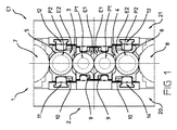
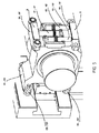
そのため本発明は、複数対の垂直部材20,21を有する保持ケージ2を備えるローリングミル1に関するものである。垂直部材20,21は、互いに離間されており、かつケージの2つの端部に配置される。各対の垂直部材20,21は、それらの間にケージをメンテナンスするためのアクセス用の窓を規定する。
Therefore, the present invention relates to a rolling mill 1 including a holding
ローリングミルは六重式のものであり、2つの上下の作動シリンダ3,4;3’,4’と2つの上下の中間シリンダ5,6と2つの上下の個別の支持シリンダ7,8とを備える一連のシリンダを備える。これらシリンダは、それらの軸が略平行となる状態で、一方が他方の上に配置されている。
The rolling mill is of a six-fold type and comprises two upper and lower working
2つの作動シリンダ3および4は、圧延されるストリップの両側に配置され、これらシリンダの離間部分によって作動時の通気間隙が規定される。各中間シリンダ5または6は、作動シリンダ3と対応する支持シリンダ7との間または作動シリンダ4と対応する支持シリンダ8との間に介在される。
The two working
作動シリンダ3または4の各々は、チャックE1によって支持されるベアリングP1の各々に回転するよう取り付けられた2つの端部を有する。同様に中間シリンダ5または6の各々は、チャックE2によって支持されるベアリングP2の各々に回転するよう取り付けられた2つの端部を有する。支持シリンダ7または8も、チャックによって支持されるベアリングの各々に回転するよう取り付けられた2つの端部を有する。
Each working
作動シリンダのチャックE1と中間シリンダのチャックE2と支持シリンダ7,8のチャックとは、把持平面に平行な方向に摺動するように、ケージを開閉できるように、またはメンテナンスおよび解体作業を容易にするように、取り付けられている。 The chuck E1 of the working cylinder, the chuck E2 of the intermediate cylinder, and the chucks of the support cylinders 7 and 8 can be opened and closed so as to slide in a direction parallel to the holding plane, or maintenance and disassembly work can be easily performed. To be attached.
ローリングミルは、支持シリンダのチャック同士の間にクランプ力を付与する手段を有する。これら手段は慣習的に液圧タイプのものであり、当業者には公知であるため図示しない。 The rolling mill has means for applying a clamping force between the chucks of the support cylinder. These means are conventionally of the hydraulic type and are known to those skilled in the art and are not shown.
ローリングミル1は、作動シリンダ3,4;3’,4’に垂直反り力(vertical camber force)を付与するための手段9と、中間シリンダに垂直反り力を付与するための手段10とをさらに備える。手段9は、2セットの液圧アクチュエータV1,V2,V3を含み、手段10は、2セットの液圧アクチュエータV1’,V2’,V3’を含む。
The rolling mill 1 further comprises means 9 for applying a vertical camber force to the working
本発明に基づくローリングミルによれば、作動シリンダ3,4;3’,4’のチャックE1および中間シリンダ5,6のチャックE2は、図5における非限定的な例示によって詳細に示される4つの支持部材O1,O2,O3,O4;O1’,O2’,O3’,O4’を備える支持体である。
According to the rolling mill according to the invention, the chuck E1 of the working
簡単化のために、図5は作動シリンダのチャックE1および中間シリンダのチャックE2の両方の概略的な形態を示していることに留意されたい。好ましくは作動シリンダのチャックE1および中間シリンダのチャックE2は同一ではなく、作動シリンダのチャックE1の寸法は好ましくは、中間シリンダのチャックE2の寸法よりも小さい。 Note that for the sake of simplicity, FIG. 5 shows a schematic configuration of both the working cylinder chuck E1 and the intermediate cylinder chuck E2. Preferably, the working cylinder chuck E1 and the intermediate cylinder chuck E2 are not identical, and the dimensions of the working cylinder chuck E1 are preferably smaller than the dimensions of the intermediate cylinder chuck E2.
4つの支持部材O1,O2,O3,O4;O1’,O2’,O3’,O4’は、チャックE1またはE2の側方に配置される。そのため作動シリンダのチャックE1の各々が、まずチャックE1の一側に突出する2つの支持部材O1,O2(つまり第1の間隙を規定する上支持部材O1および下支持部材O2)を有し、次にチャックの他側に突出する2つの支持部材O3,O4(つまり第2の間隙を規定する上支持部材O3および下支持部材O4)を有する。 The four support members O1, O2, O3, O4; O1 ', O2', O3 ', O4' are arranged on the side of the chuck E1 or E2. Therefore, each of the chucks E1 of the working cylinder first has two support members O1 and O2 (that is, an upper support member O1 and a lower support member O2 that define the first gap) projecting to one side of the chuck E1, and then Have two support members O3 and O4 (that is, an upper support member O3 and a lower support member O4 that define a second gap) projecting to the other side of the chuck.
同様に中間シリンダのチャックE2の各々も、まずチャックE2の一側に突出する2つの支持部材O1’,O2’(つまり第1の間隙を規定する上支持部材O1’および下支持部材O2’)を有し、次にチャックE2の他側に突出する2つの支持部材O3’,O4’(つまり第2の間隙を規定する上支持部材O3’および下支持部材O4’)を有する。 Similarly, each of the chucks E2 of the intermediate cylinder also has two support members O1 ′ and O2 ′ projecting to one side of the chuck E2 (that is, an upper support member O1 ′ and a lower support member O2 ′ that define the first gap). And then two support members O3 ′ and O4 ′ (that is, an upper support member O3 ′ and a lower support member O4 ′ that define a second gap) projecting to the other side of the chuck E2.
作動シリンダに垂直反り力を付与するための手段9の液圧アクチュエータV1,V2,V3は、作動シリンダ3,4;3’,4’のチャックの第1および第2の間隙に配置されるアクチュエータである。
The hydraulic actuators V1, V2, V3 of the means 9 for applying a vertical warping force to the working cylinder are actuators arranged in the first and second gaps of the chucks of the working
同じ間隙に配置されるアクチュエータV1,V2,V3は、互いに平行であり、かつ図5における非限定的な例示によって示されるようにそれらアクチュエータの長さの少なくとも一部にわたって実質的にオーバーラップしている。この例ではかつより一般的には、アクチュエータV1,V2,V3の本体は、同じ高さおいて所定の長さで延在しており、かつ任意で同じ液圧ユニットを構成してもよい。これらアクチュエータのオーバーラップは、手段9の垂直方向の寸法を抑える。 Actuators V1, V2, V3 located in the same gap are parallel to each other and substantially overlap over at least a portion of their length as shown by the non-limiting illustration in FIG. Yes. In this example and more generally, the bodies of the actuators V1, V2, V3 extend at a predetermined length at the same height, and may optionally constitute the same hydraulic unit. These actuator overlaps reduce the vertical dimension of the means 9.
アクチュエータV1,V2,V3は、ある場合には第1の方向に作動シリンダ3;3’;4;4’を反るようにするために上支持部材O1,O3と推進する(押圧する)様式で協働し、残りの場合には他の方向に作動シリンダ3;3’;4;4’を反るようにするために下支持部材O2,O4と推進様式で協働するよう意図されている。図5に図示される実施形態によれば、同じ間隙において、アクチュエータV1のロッドが上下の支持部材の一方に単純に当接するよう意図されると同時にアクチュエータV1の両側に配置される2つの他のアクチュエータV2,V3のロッドが、上下の支持部材の他方に単純に当接するよう意図されている。
Actuator V1, V2, V3 propels (presses) with upper support members O1, O3 to warp actuating
同様に、中間シリンダ5,6に垂直方向反り力を付与するための手段10の液圧アクチュエータも、中間シリンダのチャックE2の第1および第2の間隙に配置されたアクチュエータである。
Similarly, the hydraulic actuator of the
同じ間隙に配置されるアクチュエータV1’,V2’,V3’は、互いに平行であり、図5における非限定的な例示によって示されるようにそれらアクチュエータの長さの少なくとも一部にわたってオーバーラップしている。この例ではかつより一般的には、アクチュエータV1’,V2’,V3’の本体は、同じ高さにおいて所定の長さで延在しており、かつ任意で同じ液圧ユニットを構成してもよい。アクチュエータのオーバーラップは、手段10の垂直方向の寸法を抑える。
Actuators V1 ′, V2 ′, V3 ′ disposed in the same gap are parallel to each other and overlap over at least a portion of their length as shown by the non-limiting example in FIG. . In this example and more generally, the bodies of the actuators V1 ', V2', V3 'extend at a predetermined length at the same height and optionally constitute the same hydraulic unit. Good. Actuator overlap reduces the vertical dimension of the
アクチュエータV1’,V2’,V3’は、ある場合には第1の方向に中間シリンダを反るようにするために上支持部材O1’,O3’と推進様式で協働し、残りの場合には他の方向に中間シリンダを反るようにするために下支持部材O2’,O4’と推進様式で協働するよう意図されている。 Actuators V1 ', V2', V3 'cooperate in a propulsion manner with upper support members O1', O3 'in some cases to warp the intermediate cylinder in the first direction, and in the other cases Is intended to cooperate in a propulsive manner with the lower support members O2 ′, O4 ′ in order to warp the intermediate cylinder in the other direction.
アクチュエータ1,V2,V3および/またはV1’,V2’,V3’は、単動式アクチュエータであってもよい。1つの反り方向または他の反り方向に推進様式でのみ作動する場合、アクチュエータは、反り方向が反転する際に切れ目を生じない。さらにアクチュエータV1,V2,V3および/またはV1’,V2’,V3’はチャックE1またはE2に直接作用するため、反り力の制御が容易となる。 Actuators 1, V2, V3 and / or V1 ', V2', V3 'may be single-acting actuators. When operating only in a propulsion manner in one warp direction or the other warp direction, the actuator does not break when the warp direction is reversed. Furthermore, since the actuators V1, V2, V3 and / or V1 ', V2', V3 'directly act on the chuck E1 or E2, the warping force can be easily controlled.
図5に図示される実施形態によれば、同じ間隙において、アクチュエータV1’のロッドが上下の支持部材の一方と単純に当接するよう意図されると同時にアクチュエータV1’の両側に配置される他のアクチュエータV2’,V3’のロッドが上下の支持部材の他方に単純に当接するよう意図されている。 According to the embodiment illustrated in FIG. 5, in the same gap, the rod of the actuator V1 ′ is intended to simply abut against one of the upper and lower support members, while at the same time being arranged on both sides of the actuator V1 ′. The rods of the actuators V2 ′ and V3 ′ are intended to simply contact the other of the upper and lower support members.
作動シリンダ3,4;3’,4’のチャックE1は、チャックE1の両側に摺動面を有する。これら摺動面は、互いに平行であり、好ましくはケージの垂直部材に設けられるガイド面と協働するよう意図されている。
The chucks E1 of the working
同様に中間シリンダ5,6のチャックE2は、チャックE2の両側に摺動面を有する。これら摺動面は互いに平行であり、好ましくはケージの垂直部材に設けられるガイド面と協働するよう意図されている。好ましくは図5に図示されるように、作動シリンダおよび/または中間シリンダのチャックE1,E2の摺動面Sは、支持部材O1,O2,O3,O4;O1’,O2’,O3’,O4’の端部に配置されている。
Similarly, the chucks E2 of the
この実施形態によれば、摺動面Sは、互いに対してかつ把持平面に対して略平行であるとともに支持部材O1,O2,O3,O4;O1’,O2’,O3’,O4’の端部に固定されるシューを備えてもよい。 According to this embodiment, the sliding surfaces S are substantially parallel to each other and to the gripping plane and the ends of the support members O1, O2, O3, O4; O1 ′, O2 ′, O3 ′, O4 ′. You may provide the shoe fixed to a part.
代替的には、ケージ2とチャックE1,E2との間の誘導は、各間隙においてチャックの本体の側方に摺動面を提供することによって達成されてもよい。
Alternatively, guidance between the
本発明の本質的な特徴によれば、ローリングミルが、所定の範囲の直径の作動シリンダ3,4の第1の構成(図1または図2参照)から、異なる直径の作動シリンダ3’,4’の第2の構成C2(図3または図4参照)へ変形できるように、作動シリンダ3,4;3’,4’のチャックE1および中間シリンダ5,6のチャックE2は非対称的なチャックである。
According to an essential feature of the invention, the rolling mill is different from the first configuration (see FIG. 1 or FIG. 2) of working
好ましくは同じ中間シリンダ5,6は、ローリングミルの第1の構成C1から第2の構成C2へなる際にも維持される。なお別の代替案によれば中間シリンダの直径を第1の構成C1から第2の構成C2に変更することも可能である。
Preferably, the same
非対称的とは、チャックE1またはE2の支持部材O1,O2,O3,O4;O1’,O2’,O3’,O4’が、チャックE1またはE2のシリンダの支持軸から等間隔をおいて垂直部材の方向に分配されていないという事実を意味する。 Asymmetric means that the supporting members O1, O2, O3, O4 of the chuck E1 or E2; O1 ′, O2 ′, O3 ′, O4 ′ are vertical members at equal intervals from the supporting shaft of the cylinder of the chuck E1 or E2. Means the fact that it is not distributed in the direction of.
チャックE1またはE2を転回させてこれらチャックを同じアクチュエータV1,V2,V3またはV1’,V2’,V3’と係合させることによって、アクチュエータのポジションを変更することなく、シリンダの軸のポジションをオフセットすることが可能となる。 By rotating chuck E1 or E2 and engaging these chucks with the same actuator V1, V2, V3 or V1 ′, V2 ′, V3 ′, the position of the cylinder shaft is offset without changing the position of the actuator. It becomes possible to do.
非限定的な例示によって与えられる実施形態によれば、ローリングミル1の第1の構成C1は、800mmから500mmの、好ましくは670mmから520mmの、例えば620mmから570mmの直径を有する作動シリンダの取り付けを可能にしてもよく、かつローリングミルの第2の構成C2は、500mmから250mmの、好ましくは500mmから350mmの、例えば450mmから400mmの直径を有する作動シリンダの取り付けを可能にする。 According to an embodiment given by way of non-limiting illustration, the first configuration C1 of the rolling mill 1 comprises the attachment of a working cylinder having a diameter of 800 mm to 500 mm, preferably 670 mm to 520 mm, for example 620 mm to 570 mm. The second configuration C2 of the rolling mill may allow for the installation of a working cylinder having a diameter of 500 mm to 250 mm, preferably 500 mm to 350 mm, for example 450 mm to 400 mm.
有利には、ローリングミルの構成変更は、同じケージ2と、支持シリンダのチャック同士の間にクランプ力を付与するための同じ手段と、作動シリンダに垂直反り力を付与するための同じ手段9と、中間シリンダに垂直反り力を付与するための同じ手段10と、同じタイプの支持シリンダ7,8と、任意で同じ中間シリンダ5,6とを維持したまま、作動シリンダのチャックE1を転回させかつ中間シリンダのチャックE2を転回させることによって、チャックE1,E2を維持して実現される。
Advantageously, the configuration of the rolling mill is the same means for applying a clamping force between the
こうした構成変更の間、ケージ2と、支持シリンダのチャック同士の間にクランプ力を付与するための手段と、作動シリンダに垂直反り力を付与するための手段9と、中間シリンダに垂直反り力を付与するための手段10と、支持シリンダ7,8とは、ローリングミルから取り外されない。
During such a configuration change, means for applying a clamping force between the
一方で作動シリンダ3,4(および個々の作動シリンダ3’,4’)は、それらのチャックE1を用いて取り外される。チャックE1は、一度シリンダから分離されると、転回されたポジションで異なる直径を有する作動シリンダ3’,4’(および個々の作動シリンダ3,4)に組み付けられる。転回されたチャックを用いて新しい作動シリンダがケージ2内に取り付けられる。
On the other hand, the working
同様に中間シリンダ5,6がそれらのチャックE2を用いて取り外される。中間シリンダ5,6が維持される場合は、チャックE2は、ケージ2内に再度取付けられる前にケージ2の外で単純に転回される。中間シリンダが異なる直径のものと交換される場合には、チャックE2はシリンダから取り外され、異なる直径の中間シリンダに組み付けられる。続いて、新しい中間シリンダはその転回されたチャックを用いてケージ2内に取り付けられる。好ましくは同一のチャックE1が上下の作動シリンダに使用され、かつ同一のチャックE2が上下の中間シリンダに使用される。上側のシリンダのチャックE1および/またはチャックE2は単純に、下側のシリンダのチャックE1および/またはE2と置き換えられる。
Similarly, the
好ましくはローリングミル1は、中間シリンダの軸方向移動を調整するための手段を備える。有利には、これら手段は、中間シリンダの軸に平行な方向においてケージに対して摺動するよう取り付けられた支持体11,12,13,14を備える。支持体11,12,13,14は、中間シリンダ5,6に垂直反り力を付与するための手段10の液圧アクチュエータV1’,V2’,V3’を利用する。
The rolling mill 1 preferably comprises means for adjusting the axial movement of the intermediate cylinder. Advantageously, these means comprise
中間シリンダ5,6の軸方向の調整は、特に圧延されるストリップの幅にわたってのみ圧延荷重を適応させるために、中間シリンダのチャックE2と対応する液圧アクチュエータV1’,V2’,V3’との間の相対移動を伴わずに実施される。そうしたデザインは、±160mmを超える(例えば±250mmの)高度の軸方向調整移動を可能にし、ゆえに円錐セクションが後に続く円筒形長さセクションを有する従来の中間シリンダあるいはさまざまな形状の多様な輪郭を有するシリンダは漸進的なものであるため使用が可能となる。
The axial adjustment of the
本発明に基づくローリングミルおよび構成変更方法は、例えば亜鉛めっきラインまたは連続焼鈍しラインなどの焼鈍し工程を含むラインにおける用途もしくは可逆ローリングミルなどの不連続ローリングミルなどのライン外でのローリングミルにおける用途を適したものである。 Rolling mills and reconfiguration methods according to the present invention are for example in applications involving annealing processes such as galvanizing lines or continuous annealing lines or in rolling mills outside the line such as discontinuous rolling mills such as reversible rolling mills. It is suitable for use.
当然のことながら、特許請求の範囲の記載によって規定される本発明の範囲から逸脱しない限りは他の実施形態も想定され得る。 Of course, other embodiments may be envisaged without departing from the scope of the invention as defined by the appended claims.
1 ローリングミル
2 ケージ
3,4 作動シリンダ
3’,4’ 作動シリンダ
5,6 中間シリンダ
7,8 支持シリンダ
9 作動シリンダに垂直反り力を付与するための手段
10 中間シリンダに垂直反り力を付与するための手段
11,12,13,14 中間シリンダの軸方向移動を調整するための手段のための支持体
20,21 ケージの垂直部材
C1 第1の構成
C2 第2の構成
E1 作動シリンダのチャック
E2 中間シリンダのチャック
O1,O2,O3,O4 作動シリンダのチャックを支持する部材
O1’,O2’,O3’,O4’ 中間シリンダのチャックを支持する部材
S チャック(E1またはE2)の摺動面
V1,V2,V3 作動シリンダに垂直反り力を付与するための手段のためのアクチュエータ
V1’,V2’,V3’ 中間シリンダに垂直反り力を付与するための手段のためのアクチュエータ
DESCRIPTION OF SYMBOLS 1
Claims (15)
前記ローリングミル(1)は、
− 保持ケージ(2)と、
− 上下の2つの作動シリンダ(3,4;3’,4’)と上下の2つの中間シリンダ(5,6)と個々の上下の2つの支持シリンダ(7,8)とを備える、軸が略平行な状態で一方が他方の上に配置される一連のシリンダであって、
− 個々のシリンダは、チャックによって支持されるベアリングに回転するよう各々が取り付けられた2つの端部を有する、一連のシリンダと、
− 前記支持シリンダの前記チャック同士の間にクランプ力を付与するための手段と、
− 2セットの液圧アクチュエータを備える、前記作動シリンダに垂直反り力を付与するための手段(9)と、
− 2セットの液圧アクチュエータを備える、前記中間シリンダに垂直反り力を付与するための手段(10)と、
を備えており、
前記作動シリンダ(3,4;3’,4’)の前記チャック(E1)および前記中間シリンダ(5,6)の前記チャック(E2)は非対称であり、かつ、前記ローリングミルは、同じケージ(2)と前記支持シリンダの前記チャック同士の間にクランプ力を付与するための同じ手段と前記作動シリンダに垂直反り力を付与するための同じ手段(9)と前記中間シリンダに垂直反り力を付与するための同じ手段(10)と同じタイプの支持シリンダ(7,8)とを維持したまま、前記作動シリンダ(3’,4’)の前記チャック(E1)を転回することおよび前記中間シリンダの前記チャック(E2)を転回することによって前記チャック(E1,E2)を維持したまま第1の作動シリンダ直径範囲構成(C1)から異なる作動シリンダ直径(3,4)を伴う第2の構成(C2)へ変更され、
− 前記作動シリンダ(3,4;3’,4’)の前記チャック(E1)のためかつ前記中間シリンダ(5,6)の前記チャック(E2)のために、4つの支持部材(O1,O2,O3,O4;O1’,O2’,O3’,O4’)を備える支持体が使用され、これら支持部材(O1,O2,O3,O4;O1’,O2’,O3’,O4’)は、まず2つの支持部材(O1,O2,O1’,O2’)が前記チャックの一側に突出するようにつまり上支持部材(O1;O1’)および下支持部材(O2,O2’)が第1の間隙を規定するように、かつ次に2つの支持部材(O3,O4;O3’,O4’)が前記チャックの他側に突出するようにつまり上支持部材(O3;O3’)および下支持部材(O4;O4’)が第2の間隙を規定するように、側方に配置されており、
− 前記作動シリンダに垂直反り力を付与するための前記手段(9)の前記液圧アクチュエータは、前記作動シリンダ(3,4;3’,4’)の前記チャックの前記第1および第2の間隙に配置されるアクチュエータであり、該アクチュエータ(V1,V2,V3)は、オーバーラップするよう1つの同じ間隙に配置されており、前記アクチュエータは、ある場合には前記作動シリンダ(3,3;4’,4’)を第1の方向に反るようにするために前記上支持部材(O1,O3)と推進様式で協働し、かつ別の場合には前記作動シリンダ(3;3’;4;4’)を他の方向に反るようにするために前記下支持部材(O2,O4)と推進様式で協働しよう意図されており、
− 前記中間シリンダ(5,6)に垂直反り力を付与するための前記手段(10)の前記液圧アクチュエータは、前記中間シリンダの前記チャックの前記第1および第2の間隙に配置されたアクチュエータであり、該アクチュエータ(V1’,V2’,V3’)は、オーバーラップするよう1つの同じ間隙に配置されており、前記アクチュエータは、ある場合は前記中間シリンダを第1の方向に反るようにするために前記上支持部材(O1’,O3’)と推進様式で協働し、かつ別の場合には前記中間シリンダの他の方向に反るようにするために前記下支持部材(O2’,O4’)と推進様式で協働するよう意図されていることを特徴とする方法。 A method for changing the configuration of a rolling mill (1),
The rolling mill (1)
-A holding cage (2);
The shaft comprising two upper and lower working cylinders (3, 4; 3 ′, 4 ′), two upper and lower intermediate cylinders (5, 6) and two individual upper and lower support cylinders (7, 8); A series of cylinders arranged one above the other in a substantially parallel state,
Each cylinder has a series of cylinders, each having two ends, each mounted to rotate to a bearing supported by a chuck;
-Means for applying a clamping force between the chucks of the support cylinder;
-Means (9) for applying a vertical warping force to the working cylinder, comprising two sets of hydraulic actuators;
-Means (10) for applying a vertical warping force to said intermediate cylinder, comprising two sets of hydraulic actuators;
With
The chuck (E1) of the working cylinder (3, 4; 3 ′, 4 ′) and the chuck (E2) of the intermediate cylinder (5, 6) are asymmetric, and the rolling mill has the same cage ( 2) and the same means for applying a clamping force between the chucks of the support cylinder and the same means (9) for applying a vertical warping force to the working cylinder and a vertical warping force to the intermediate cylinder Rotating the chuck (E1) of the working cylinder (3 ′, 4 ′) and maintaining the same means (10) and the same type of support cylinder (7, 8) Different working cylinder diameters (3, 4) from the first working cylinder diameter range configuration (C1) while maintaining the chucks (E1, E2) by rotating the chuck (E2) Changed to the second configuration (C2) with
-Four support members (O1, O2) for the chuck (E1) of the working cylinder (3, 4; 3 ', 4') and for the chuck (E2) of the intermediate cylinder (5, 6) , O3, O4; O1 ′, O2 ′, O3 ′, O4 ′), and these support members (O1, O2, O3, O4; O1 ′, O2 ′, O3 ′, O4 ′) are used. First, the two support members (O1, O2, O1 ′, O2 ′) are protruded to one side of the chuck, that is, the upper support member (O1; O1 ′) and the lower support member (O2, O2 ′) are the first ones. 1 so as to define a gap of 1 and then the two support members (O3, O4; O3 ′, O4 ′) project to the other side of the chuck, ie the upper support member (O3; O3 ′) and the lower The support members (O4; O4 ′) are arranged laterally so as to define the second gap;
The hydraulic actuator of the means (9) for applying a vertical warping force to the working cylinder is the first and second of the chuck of the working cylinder (3, 4; 3 ′, 4 ′); An actuator arranged in a gap, the actuators (V1, V2, V3) being arranged in one and the same gap so that they overlap, in some cases the actuators (3, 3; 4 ′, 4 ′) cooperates with the upper support members (O1, O3) in a propulsion manner to warp in the first direction, and in other cases the working cylinder (3; 3 ′) 4; 4 ′) is intended to cooperate in a propulsion manner with the lower support members (O2, O4) in order to warp in the other direction;
The hydraulic actuator of the means (10) for applying a vertical warping force to the intermediate cylinder (5, 6) is an actuator arranged in the first and second gaps of the chuck of the intermediate cylinder; The actuators (V1 ′, V2 ′, V3 ′) are arranged in one and the same gap so as to overlap, and the actuator, in some cases, warps the intermediate cylinder in a first direction. In order to cooperate with the upper support members (O1 ′, O3 ′) in a propulsion manner and in other cases to warp in the other direction of the intermediate cylinder. A method characterized in that it is intended to cooperate with ', O4') in a propulsion style.
前記支持体は、前記チャック(E2)と前記液圧アクチュエータ(V1’,V2’,V3’)との間の相対移動を伴わずに前記中間シリンダの軸方向移動が実施されるように、前記中間シリンダ(5,6)に垂直反り力を付与するための前記手段の前記液圧アクチュエータ(V1’,V2’,V3’)を用いることを特徴とする請求項1から請求項4のいずれか一項に記載の方法。 The rolling mill (1) comprises means for adjusting the axial movement of the intermediate cylinder, these means being slidably attached to the cage (11, 12, 13, 14)
The support is moved in the axial direction of the intermediate cylinder without relative movement between the chuck (E2) and the hydraulic actuators (V1 ′, V2 ′, V3 ′). 5. The hydraulic actuator (V1 ′, V2 ′, V3 ′) of the means for applying a vertical warping force to the intermediate cylinder (5, 6) is used. The method according to one item.
前記作動シリンダおよび/または前記中間シリンダの前記チャック(E1,E2)の摺動面(S)は、前記支持部材(O1,O2,O3,O4;O1’,O2’,O3’,O4’)の前記端部に配置されていることを特徴とする請求項1から請求項7のいずれか一項に記載の方法。 The chucks (E1, E2) of the working cylinder and the intermediate cylinder have a sliding surface (S) intended to cooperate with the guide surface of the cage;
The sliding surface (S) of the chuck (E1, E2) of the working cylinder and / or the intermediate cylinder is the support member (O1, O2, O3, O4; O1 ′, O2 ′, O3 ′, O4 ′). 8. The method according to any one of claims 1 to 7, wherein the method is disposed at the end of the device.
前記ローリングミル(1)は、
− 保持ケージ(2)と、
− 上下の2つの作動シリンダ(3,4;3’,4’)と上下の2つの中間シリンダ(5,6)と個々の上下の2つの支持シリンダ(7,8)とを備える、軸が略平行な状態で一方が他方の上に配置される一連のシリンダであって、
− 各シリンダは、チャックによって支持されるベアリングに回転するよう各々が取り付けられる2つの端部を有する、一連のベアリングと、
− 前記支持シリンダの前記チャック同士の間にクランプ力を付与するための手段と、
− 2セットの液圧アクチュエータを備える、前記作動シリンダに垂直反り力を付与するための手段(9)と、
− 2セットの液圧アクチュエータを備える、前記中間シリンダに垂直反り力を付与するための手段(10)と、
を備えており、
− 前記作動シリンダ(3,4;3’,4’)の前記チャック(E1)および前記中間シリンダの前記チャック(E2)は、4つの支持部材(O1,O2,O3,O4;O1’,O2’,O3’,O4’)を備える支持体であり、これら支持部材(O1,O2,O3,O4;O1’,O2’,O3’,O4’)は、まず2つの支持部材(O1,O2;O1’,O2’)が前記チャックの一側に突出するようにつまり上支持部材(O1,O1’)および下支持部材(O2;O2’)が第1の間隙を規定するように、かつ次に2つの支持部材(O3,O4;O3’,O4’)が前記チャックの他側に突出するようにつまり上支持部材(O3,O3’)および下支持部材(O4,O4’)が第2の間隙を規定するように、側方に配置されており、
− 前記作動シリンダに垂直反り力を付与するための前記手段(9)の前記液圧アクチュエータは、前記作動シリンダ(3,4;3’,4’)の前記チャックの前記第1および第2の間隙に配置されたアクチュエータであり、該アクチュエータ(V1,V2,V3)は、オーバーラップするように1つの同じ間隙に配置されており、前記アクチュエータは、ある場合には第1の方向に前記作動シリンダ(3;3’;4;4’)を反るようにするために前記上支持部材(O1,O3)と推進様式で協働し、かつ別の場合には他の方向に前記作動シリンダ(3;3’;4;4’)を反るようにするために前記下支持部材(O2,O4)と推進様式で協働するよう意図されており、
− 前記中間シリンダ(5,6)に垂直反り力を付与するための前記手段(10)の前記液圧アクチュエータは、前記中間シリンダの前記チャックの前記第1および第2の間隙に配置されたアクチュエータであり、前記アクチュエータ(V1’,V2’,V3’)は、オーバーラップするように1つの同じ間隙に配置されており、前記アクチュエータは、ある場合には第1の方向に前記中間シリンダを反るようにするために前記上支持部材(O1’,O3’)と推進様式で協働し、かつ別の場合には他の方向に前記中間シリンダを反るようにするために前記下支持部材(O2’,O4’)と推進様式で協働するよう意図されており、
− 前記作動シリンダ(3,4;3’,4’)の前記チャック(E1)および前記中間シリンダ(5,6)の前記チャック(E2)は、前記ローリングミルが、同じケージ(2)と前記支持シリンダの前記チャック同士の間にクランプ力を付与するための同じ手段と前記作動シリンダに垂直反り力を付与するための同じ手段(9)と前記中間シリンダに垂直反り力を付与するための同じ手段(10)と同じタイプの前記支持シリンダ(7,8)とを維持したまま、前記作動シリンダの前記チャック(E1)の転回および前記中間シリンダの前記チャック(E2)の転回によって前記チャック(E1,E2)を維持したまま1つの作動シリンダ(3,4)直径範囲を伴う第1の構成(C1)から異なる作動シリンダ(3,4)直径を伴う第2の構成(C2)へ変更可能なように、非対称的なチャックであることを特徴とするローリングミル。 A rolling mill (1),
The rolling mill (1)
-A holding cage (2);
The shaft comprising two upper and lower working cylinders (3, 4; 3 ′, 4 ′), two upper and lower intermediate cylinders (5, 6) and two individual upper and lower support cylinders (7, 8); A series of cylinders arranged one above the other in a substantially parallel state,
Each cylinder has a series of bearings with two ends each attached to rotate to a bearing supported by a chuck;
-Means for applying a clamping force between the chucks of the support cylinder;
-Means (9) for applying a vertical warping force to the working cylinder, comprising two sets of hydraulic actuators;
-Means (10) for applying a vertical warping force to said intermediate cylinder, comprising two sets of hydraulic actuators;
With
The chuck (E1) of the working cylinder (3, 4; 3 ′, 4 ′) and the chuck (E2) of the intermediate cylinder have four support members (O1, O2, O3, O4; O1 ′, O2). ', O3', O4 '), and these support members (O1, O2, O3, O4; O1', O2 ', O3', O4 ') are first provided with two support members (O1, O2). O1 ′, O2 ′) projecting to one side of the chuck, ie, the upper support member (O1, O1 ′) and the lower support member (O2; O2 ′) define the first gap; Next, the two support members (O3, O4; O3 ′, O4 ′) are protruded to the other side of the chuck, that is, the upper support member (O3, O3 ′) and the lower support member (O4, O4 ′) are the first ones. Are located on the sides to define a gap of two,
The hydraulic actuator of the means (9) for applying a vertical warping force to the working cylinder is the first and second of the chuck of the working cylinder (3, 4; 3 ′, 4 ′); An actuator arranged in a gap, the actuators (V1, V2, V3) being arranged in one and the same gap so as to overlap, said actuator in some cases said actuation in a first direction Cooperating with the upper support members (O1, O3) in a propulsion manner to warp the cylinders (3; 3 ';4;4') and in other cases the working cylinders in the other direction (3; 3 ';4;4') is intended to cooperate in a propulsion manner with the lower support members (O2, O4) to warp (3; 3 ';4;4');
The hydraulic actuator of the means (10) for applying a vertical warping force to the intermediate cylinder (5, 6) is an actuator arranged in the first and second gaps of the chuck of the intermediate cylinder; The actuators (V1 ′, V2 ′, V3 ′) are arranged in one and the same gap so as to overlap, and the actuator counteracts the intermediate cylinder in a first direction in some cases. The lower support member cooperates with the upper support members (O1 ′, O3 ′) in a propulsion manner to cause the intermediate cylinder to warp in other directions. (O2 ', O4') and is intended to collaborate in a promotion style,
The chuck (E1) of the working cylinders (3, 4; 3 ′, 4 ′) and the chuck (E2) of the intermediate cylinders (5, 6) have the same rolling mill as the cage (2); The same means for applying a clamping force between the chucks of the support cylinder, the same means (9) for applying a vertical warping force to the working cylinder, and the same for applying a vertical warping force to the intermediate cylinder While maintaining the support cylinder (7, 8) of the same type as the means (10), the chuck (E1) is rotated by turning the chuck (E1) of the working cylinder and the chuck (E2) of the intermediate cylinder. , E2) while maintaining one working cylinder (3,4) diameter range from the first construction (C1) to a second construction with a different working cylinder (3,4) diameter. C2) so as to be changed to, a rolling mill, which is a asymmetric chuck.
Applications Claiming Priority (3)
| Application Number | Priority Date | Filing Date | Title |
|---|---|---|---|
| FR1354824A FR3006211B1 (en) | 2013-05-28 | 2013-05-28 | METHOD FOR CHANGING THE CONFIGURATION OF A ROLLING MILL AND ROLLING MILL FOR IMPLEMENTING THE METHOD |
| FR1354824 | 2013-05-28 | ||
| PCT/FR2014/051232 WO2014191671A1 (en) | 2013-05-28 | 2014-05-27 | Method for changing the configuration of a rolling mill and rolling mill for the implementation of said method |
Publications (1)
| Publication Number | Publication Date |
|---|---|
| JP2016520004A true JP2016520004A (en) | 2016-07-11 |
Family
ID=49151075
Family Applications (1)
| Application Number | Title | Priority Date | Filing Date |
|---|---|---|---|
| JP2016516220A Pending JP2016520004A (en) | 2013-05-28 | 2014-05-27 | Method for changing the configuration of a rolling mill and rolling mill for carrying out the method |
Country Status (8)
| Country | Link |
|---|---|
| US (1) | US10195652B2 (en) |
| EP (1) | EP3003590B1 (en) |
| JP (1) | JP2016520004A (en) |
| CN (1) | CN105339102B (en) |
| ES (1) | ES2662218T3 (en) |
| FR (1) | FR3006211B1 (en) |
| TW (1) | TW201509556A (en) |
| WO (1) | WO2014191671A1 (en) |
Cited By (1)
| Publication number | Priority date | Publication date | Assignee | Title |
|---|---|---|---|---|
| JP2023510090A (en) * | 2019-12-11 | 2023-03-13 | エス・エム・エス・グループ・ゲゼルシャフト・ミト・ベシュレンクテル・ハフツング | Hot rolling stands for hot rolling mills and for the manufacture of flat metal products, hot rolling mills and methods for operating hot rolling mills |
Citations (2)
| Publication number | Priority date | Publication date | Assignee | Title |
|---|---|---|---|---|
| JPS62275508A (en) * | 1986-05-21 | 1987-11-30 | Hitachi Ltd | Six-high rolling mill |
| JPS6434505A (en) * | 1987-07-30 | 1989-02-06 | Hitachi Ltd | Bearing box for rolling mill |
Family Cites Families (9)
| Publication number | Priority date | Publication date | Assignee | Title |
|---|---|---|---|---|
| JPS5581009A (en) | 1978-12-14 | 1980-06-18 | Nippon Steel Corp | Skin-pass rolling shape control method of cold rolled hoop after continuous annealing and equipment thereof |
| DE3261730D1 (en) | 1981-02-28 | 1985-02-14 | Schloemann Siemag Ag | Roll stand |
| JPH0753285B2 (en) * | 1984-03-30 | 1995-06-07 | 株式会社日立製作所 | Rolling mill with work roll bearing box |
| JPH02280910A (en) * | 1989-04-20 | 1990-11-16 | Kawasaki Steel Corp | Rolling machine |
| EP0543014B2 (en) | 1991-05-16 | 2004-10-27 | JFE Steel Corporation | Six-stage rolling mill |
| IT1280176B1 (en) * | 1995-05-25 | 1998-01-05 | Danieli Off Mecc | BENDING-BALANCING BLOCK FOR FOURTH ROLLING CAGE FOR TAPES OR SHEETS |
| FR2851942B1 (en) * | 2003-03-05 | 2006-04-28 | METHOD FOR CHANGING THE CONFIGURATION OF A ROLLING MILL AND IMPROVED ROLLING MILL FOR IMPLEMENTING THE METHOD | |
| TWI247633B (en) * | 2003-04-02 | 2006-01-21 | Jfe Steel Corp | Cross-rolling rolling machine and method of using same |
| US9120134B2 (en) * | 2011-10-26 | 2015-09-01 | I2S, Llc | Methods of shifting and bending rolls in a rolling mill |
-
2013
- 2013-05-28 FR FR1354824A patent/FR3006211B1/en not_active Expired - Fee Related
-
2014
- 2014-05-27 WO PCT/FR2014/051232 patent/WO2014191671A1/en active Application Filing
- 2014-05-27 CN CN201480030588.3A patent/CN105339102B/en active Active
- 2014-05-27 JP JP2016516220A patent/JP2016520004A/en active Pending
- 2014-05-27 US US14/894,263 patent/US10195652B2/en active Active
- 2014-05-27 ES ES14731729.1T patent/ES2662218T3/en active Active
- 2014-05-27 EP EP14731729.1A patent/EP3003590B1/en active Active
- 2014-05-28 TW TW103118686A patent/TW201509556A/en unknown
Patent Citations (2)
| Publication number | Priority date | Publication date | Assignee | Title |
|---|---|---|---|---|
| JPS62275508A (en) * | 1986-05-21 | 1987-11-30 | Hitachi Ltd | Six-high rolling mill |
| JPS6434505A (en) * | 1987-07-30 | 1989-02-06 | Hitachi Ltd | Bearing box for rolling mill |
Cited By (1)
| Publication number | Priority date | Publication date | Assignee | Title |
|---|---|---|---|---|
| JP2023510090A (en) * | 2019-12-11 | 2023-03-13 | エス・エム・エス・グループ・ゲゼルシャフト・ミト・ベシュレンクテル・ハフツング | Hot rolling stands for hot rolling mills and for the manufacture of flat metal products, hot rolling mills and methods for operating hot rolling mills |
Also Published As
| Publication number | Publication date |
|---|---|
| CN105339102B (en) | 2018-07-03 |
| ES2662218T3 (en) | 2018-04-05 |
| FR3006211A1 (en) | 2014-12-05 |
| EP3003590B1 (en) | 2017-12-20 |
| US10195652B2 (en) | 2019-02-05 |
| TW201509556A (en) | 2015-03-16 |
| CN105339102A (en) | 2016-02-17 |
| US20160107212A1 (en) | 2016-04-21 |
| WO2014191671A1 (en) | 2014-12-04 |
| FR3006211B1 (en) | 2015-05-15 |
| EP3003590A1 (en) | 2016-04-13 |
Similar Documents
| Publication | Publication Date | Title |
|---|---|---|
| KR20050084993A (en) | Method for increasing the range of production of a metal product rolling installation and installation therefor | |
| KR20200033891A (en) | Micro-organized surface through low pressure rolling | |
| US8616037B2 (en) | Re-turning plant for rollers of a roller mill | |
| US8695392B2 (en) | Rolling mill and tandem rolling mill having the same | |
| JP2016520004A (en) | Method for changing the configuration of a rolling mill and rolling mill for carrying out the method | |
| KR20200141997A (en) | Device and method for guiding a metal strip comprising a wear body with a support element | |
| CN104176421A (en) | Strip steel conveying device | |
| CA2835680C (en) | Method and apparatus for producing metal sections with a closely toleranced chamber dimension | |
| ATE522354T1 (en) | DEVICE FOR PROCESSING A MATERIAL WEB BETWEEN TWO OPPOSITELY DRIVEN WORK ROLLS | |
| JP6119731B2 (en) | Two-stage rolling mill and roll shift method | |
| CN105478486A (en) | Replacement device for backup roller and intermediate roller of rolling mill | |
| JP5044191B2 (en) | Plate shape correction device | |
| RU2653520C1 (en) | Device for thermal flattening of shafts | |
| CN104043650B (en) | Method for the equipment of the working roll of rotary rolling mill and for changing the roller | |
| JP4943811B2 (en) | Plate shape correction device | |
| JP2011526839A (en) | Roll array | |
| WO2016208659A1 (en) | Roll-molding device | |
| KR101332780B1 (en) | Idle straightening apparatus for regulating angle of steel | |
| JP5861670B2 (en) | Rolling mill roll shift roll apparatus, rolling mill roll shift roll forming method, and rolling mill | |
| JP5164766B2 (en) | Long work reversing roller | |
| CN203695676U (en) | Cone rolling tool for symmetric rolling machine | |
| RU59076U1 (en) | SHAFT COATING DEVICE | |
| JPH02290609A (en) | Chockless roll bending device of rolling mill | |
| JPH05154519A (en) | Backup roll device for rolling mill | |
| JPS61111707A (en) | Rolling mill |
Legal Events
| Date | Code | Title | Description |
|---|---|---|---|
| A621 | Written request for application examination |
Free format text: JAPANESE INTERMEDIATE CODE: A621 Effective date: 20170510 |
|
| A131 | Notification of reasons for refusal |
Free format text: JAPANESE INTERMEDIATE CODE: A131 Effective date: 20180521 |
|
| A977 | Report on retrieval |
Free format text: JAPANESE INTERMEDIATE CODE: A971007 Effective date: 20180524 |
|
| A02 | Decision of refusal |
Free format text: JAPANESE INTERMEDIATE CODE: A02 Effective date: 20181217 |