JP2016518870A - System including a guide wire for detecting fluid pressure - Google Patents
System including a guide wire for detecting fluid pressure Download PDFInfo
- Publication number
- JP2016518870A JP2016518870A JP2016501215A JP2016501215A JP2016518870A JP 2016518870 A JP2016518870 A JP 2016518870A JP 2016501215 A JP2016501215 A JP 2016501215A JP 2016501215 A JP2016501215 A JP 2016501215A JP 2016518870 A JP2016518870 A JP 2016518870A
- Authority
- JP
- Japan
- Prior art keywords
- guidewire
- pressure
- circuit
- electrode
- wire
- Prior art date
- Legal status (The legal status is an assumption and is not a legal conclusion. Google has not performed a legal analysis and makes no representation as to the accuracy of the status listed.)
- Pending
Links
- 0 CCCC(CC1)CCC1*=C Chemical compound CCCC(CC1)CCC1*=C 0.000 description 1
Images


Classifications
-
- A—HUMAN NECESSITIES
- A61—MEDICAL OR VETERINARY SCIENCE; HYGIENE
- A61B—DIAGNOSIS; SURGERY; IDENTIFICATION
- A61B5/00—Measuring for diagnostic purposes; Identification of persons
- A61B5/02—Detecting, measuring or recording pulse, heart rate, blood pressure or blood flow; Combined pulse/heart-rate/blood pressure determination; Evaluating a cardiovascular condition not otherwise provided for, e.g. using combinations of techniques provided for in this group with electrocardiography or electroauscultation; Heart catheters for measuring blood pressure
- A61B5/021—Measuring pressure in heart or blood vessels
- A61B5/0215—Measuring pressure in heart or blood vessels by means inserted into the body
-
- A—HUMAN NECESSITIES
- A61—MEDICAL OR VETERINARY SCIENCE; HYGIENE
- A61B—DIAGNOSIS; SURGERY; IDENTIFICATION
- A61B5/00—Measuring for diagnostic purposes; Identification of persons
- A61B5/68—Arrangements of detecting, measuring or recording means, e.g. sensors, in relation to patient
- A61B5/6846—Arrangements of detecting, measuring or recording means, e.g. sensors, in relation to patient specially adapted to be brought in contact with an internal body part, i.e. invasive
- A61B5/6847—Arrangements of detecting, measuring or recording means, e.g. sensors, in relation to patient specially adapted to be brought in contact with an internal body part, i.e. invasive mounted on an invasive device
- A61B5/6851—Guide wires
-
- A—HUMAN NECESSITIES
- A61—MEDICAL OR VETERINARY SCIENCE; HYGIENE
- A61B—DIAGNOSIS; SURGERY; IDENTIFICATION
- A61B2562/00—Details of sensors; Constructional details of sensor housings or probes; Accessories for sensors
- A61B2562/02—Details of sensors specially adapted for in-vivo measurements
- A61B2562/0209—Special features of electrodes classified in A61B5/24, A61B5/25, A61B5/283, A61B5/291, A61B5/296, A61B5/053
- A61B2562/0214—Capacitive electrodes
-
- A—HUMAN NECESSITIES
- A61—MEDICAL OR VETERINARY SCIENCE; HYGIENE
- A61B—DIAGNOSIS; SURGERY; IDENTIFICATION
- A61B2562/00—Details of sensors; Constructional details of sensor housings or probes; Accessories for sensors
- A61B2562/02—Details of sensors specially adapted for in-vivo measurements
- A61B2562/0209—Special features of electrodes classified in A61B5/24, A61B5/25, A61B5/283, A61B5/291, A61B5/296, A61B5/053
- A61B2562/0217—Electrolyte containing
-
- A—HUMAN NECESSITIES
- A61—MEDICAL OR VETERINARY SCIENCE; HYGIENE
- A61B—DIAGNOSIS; SURGERY; IDENTIFICATION
- A61B2562/00—Details of sensors; Constructional details of sensor housings or probes; Accessories for sensors
- A61B2562/02—Details of sensors specially adapted for in-vivo measurements
- A61B2562/0247—Pressure sensors
-
- A—HUMAN NECESSITIES
- A61—MEDICAL OR VETERINARY SCIENCE; HYGIENE
- A61B—DIAGNOSIS; SURGERY; IDENTIFICATION
- A61B2562/00—Details of sensors; Constructional details of sensor housings or probes; Accessories for sensors
- A61B2562/02—Details of sensors specially adapted for in-vivo measurements
- A61B2562/028—Microscale sensors, e.g. electromechanical sensors [MEMS]
-
- A—HUMAN NECESSITIES
- A61—MEDICAL OR VETERINARY SCIENCE; HYGIENE
- A61M—DEVICES FOR INTRODUCING MEDIA INTO, OR ONTO, THE BODY; DEVICES FOR TRANSDUCING BODY MEDIA OR FOR TAKING MEDIA FROM THE BODY; DEVICES FOR PRODUCING OR ENDING SLEEP OR STUPOR
- A61M25/00—Catheters; Hollow probes
- A61M2025/0001—Catheters; Hollow probes for pressure measurement
- A61M2025/0002—Catheters; Hollow probes for pressure measurement with a pressure sensor at the distal end
-
- A—HUMAN NECESSITIES
- A61—MEDICAL OR VETERINARY SCIENCE; HYGIENE
- A61M—DEVICES FOR INTRODUCING MEDIA INTO, OR ONTO, THE BODY; DEVICES FOR TRANSDUCING BODY MEDIA OR FOR TAKING MEDIA FROM THE BODY; DEVICES FOR PRODUCING OR ENDING SLEEP OR STUPOR
- A61M25/00—Catheters; Hollow probes
- A61M25/01—Introducing, guiding, advancing, emplacing or holding catheters
- A61M25/09—Guide wires
- A61M2025/09175—Guide wires having specific characteristics at the distal tip
- A61M2025/09183—Guide wires having specific characteristics at the distal tip having tools at the distal tip
Abstract
血管内の血圧を検出するためのシステムはガイドワイヤと、ガイドワイヤの遠位端に提供されたLC共振回路とを含む。共振回路は、外部にある流体の圧力変化に応じて変動する共振周波数を共振回路が有するよう、ガイドワイヤの外部にある流体の圧力の変化に応答する非LC共振回路であってよい。A system for detecting blood pressure in a blood vessel includes a guide wire and an LC resonant circuit provided at the distal end of the guide wire. The resonant circuit may be a non-LC resonant circuit that responds to changes in the pressure of the fluid outside the guidewire so that the resonant circuit has a resonant frequency that varies in response to changes in the pressure of the fluid outside.
Description
本発明は、近接性が制限された人体、動物、または他の環境の内部の局所的圧力情報を抽出するいくつかの方法に関する。本発明は、特に血圧測定値の取得において有用である。 The present invention relates to several methods for extracting local pressure information inside a human body, animal, or other environment with limited proximity. The present invention is particularly useful in obtaining blood pressure measurements.
血圧などの圧力のインターベンショナルカーディオロジー測定はガイドワイヤを介して得られる。冠血流予備量比またはFFRと呼ばれる手法は、血管閉塞の近位及び遠位の圧力比を判定するためのものである。この圧力比は、閉塞の処置方法を決定するために使用される。現在使用されるセンサに関する問題は、センサを14/1000インチのガイドワイヤ内に納めるために小型化が要求される点である。圧力に比例する信号を抽出するための検出方法ならびに対応する電子回路が開示される。 An interventional cardiology measurement of pressure such as blood pressure is obtained via a guide wire. A technique called coronary flow reserve ratio or FFR is for determining the proximal and distal pressure ratio of a vascular occlusion. This pressure ratio is used to determine how to treat the occlusion. A problem with currently used sensors is that miniaturization is required to fit the sensor within a 14/1000 inch guidewire. A detection method and corresponding electronic circuit for extracting a signal proportional to pressure is disclosed.
ガイドワイヤを厳密に機構的ツールまたはガイドツールとしてのみ利用する代わりに、プレッシャワイヤ及びフローワイヤが二重機能ガイドワイヤとして格上げされると、機構的誘導及び血流力学情報が同時に提供されることとなる。FAMEスタディの結果に基づき、FFRの測定は普及しつつあり、払い戻しの対象となっている国もある。現在、ラディ(STJにより合併された)及びボルケーノの2種類のプレッシャワイヤが市販されており、これらのFFRガイドワイヤはいずれも、近位ワイヤ端部において3つの電気接点を有するプッシュオンハンドルを通して接続されたIC圧力センサ(歪みゲージ式)を使用する。ラディガイドワイヤの場合、コネクタハンドルは圧力値をディスプレイシステムにワイヤレスで送信する。このことは、ケーブル接続に対する改善であるが、非常に煩雑である。これは、カテーテルが挿入される度に、カテーテルがワイヤ上で進められる前に、コネクタハンドルが近位ワイヤ端部から切り離される必要があるためである。 Instead of using a guide wire strictly as a mechanical or guide tool, mechanical pressure and hemodynamic information are provided simultaneously when the pressure wire and flow wire are promoted as dual function guide wires; Become. Based on the results of the FAME study, FFR measurements are becoming popular and some countries are subject to refunds. Currently, there are two types of pressure wires on the market, Radi (merged by STJ) and Volcano, both of which are connected through a push-on handle with three electrical contacts at the proximal wire end. IC pressure sensor (strain gauge type) is used. In the case of a radiant guidewire, the connector handle wirelessly transmits the pressure value to the display system. This is an improvement over cable connections, but is very cumbersome. This is because each time a catheter is inserted, the connector handle must be disconnected from the proximal wire end before the catheter is advanced over the wire.
2012年1月30日出願の国際特許出願PCT/US2012/023130号に記載される(本明細書における図1〜図19参照)ように、血圧変化を検出するための共振回路は、2つの電気的接続のみが作られる必要がある場合において、利用が可能である。患者の身体が接地帰還経路として使用される場合、ガイドワイヤ自体を電気コネクタとして利用することが可能である。ガイドワイヤがシース(ガイドカテーテル)に進入するボートにおいて高周波数電気的接続を提供するために、シースとガイドワイヤとの間の静電容量を使用することも可能となり得る。このことは、現在使用される歪みゲージの手法(供給電圧が必要であるため、少なくとも3つの電気的接続が必要となる)に対する利点を有する。電気的接続が3つ存在すると、ワイヤ構成とそれにともなうワイヤの取り扱いが著しく影響される。係るワイヤは標準的ガイドワイヤのような取り扱いができず、製造費が大きくなる。このことは上述の応用では克服される。一方、顕著な負荷(身体静電容量)を駆動するにあたっての十分な感度を有する、14/1000インチのガイドワイヤ内に収まる小型の容量性センサは製造が困難である。したがって、低いインピーダンス負荷を駆動することが可能な高い感度を有し、且つ高感度FFR検出器システム用の、小型の受動的圧力センサが必要となる。 As described in International Patent Application No. PCT / US2012 / 023130 filed on Jan. 30, 2012 (see FIGS. 1 to 19 in this specification), a resonant circuit for detecting a blood pressure change has two electrical circuits. It can be used when only a global connection needs to be made. When the patient's body is used as a ground return path, the guidewire itself can be used as an electrical connector. It may also be possible to use the capacitance between the sheath and the guidewire to provide a high frequency electrical connection in a boat where the guidewire enters the sheath (guide catheter). This has the advantage over currently used strain gauge techniques (at least three electrical connections are required because a supply voltage is required). The presence of three electrical connections significantly affects the wire configuration and associated wire handling. Such a wire cannot be handled like a standard guide wire, resulting in high manufacturing costs. This is overcome in the applications described above. On the other hand, a small capacitive sensor that fits within a 14/1000 inch guidewire with sufficient sensitivity to drive a significant load (body capacitance) is difficult to manufacture. Therefore, there is a need for a small passive pressure sensor for high sensitivity and high sensitivity FFR detector systems that can drive low impedance loads.
現在使用される市販のFFRワイヤの能動的電力供給においては、電気配線がワイヤの全長に沿って伸びることが要求される。しかしそれにより完全性が著しく損なわれ、それにともない標準的ガイドワイヤの取り扱い特性も損なわれてしまう。米国特許出願公開第2001/0051769(A1)号(ラディ)は、それぞれ患者内部の電極上において内部及び外部の接地電極を利用することにより、近位ワイヤ接点に対して接点の個数を低減する方法について説明する。一方、再び、この提案される解決策は能動的に電力供給されるセンサに依存する。能動的に電力供給されるセンサでは、圧力センサに電力を供給するために著しい電流が患者身体を通して流れる。したかって、受動的な圧力検出容量性要素を使用する改善された検出及び接続の方式が必要とされる。 The active power supply of currently used commercial FFR wires requires that the electrical wiring extend along the entire length of the wire. However, this significantly impairs completeness and, as a result, the handling characteristics of standard guidewires. US Patent Application Publication No. 2001/0051769 (A1) (Radi) describes a method for reducing the number of contacts relative to a proximal wire contact by utilizing an internal and external ground electrode on each patient internal electrode. Will be described. On the other hand, again, this proposed solution relies on actively powered sensors. In actively powered sensors, significant current flows through the patient body to power the pressure sensor. Therefore, there is a need for an improved detection and connection scheme that uses passive pressure sensing capacitive elements.
本発明は生体内の流体圧力測定の最適化及び支援を行うことを目的とする。本発明は、部分的に、測定回路が対象の患者に対して有する接点を最小化することにより、係る目的について検討する。本発明は、使用の方法が簡素化されしたがって促進される、測定装置の変更例も求めるものである。 An object of the present invention is to optimize and support fluid pressure measurement in a living body. The present invention considers such objectives, in part, by minimizing the contacts that the measurement circuit has on the subject patient. The present invention also seeks a variation of the measuring device in which the method of use is simplified and therefore facilitated.
したがって本発明の目的は、部分的には、血管内の血圧を1つの接点により検出するためのシステム(装置及び方法)を提供することである。付随的に本発明の目的は、部分的には、血管内の血圧の半ワイヤレス検出のための装置及び方法を提供することである。本発明の目的は、受動的な圧力検出容量性要素を使用する改善された検出及び接続の方式を提供することでもある。 Accordingly, it is an object of the present invention to provide, in part, a system (apparatus and method) for detecting blood pressure in a blood vessel with a single contact. Additionally, it is an object of the present invention, in part, to provide an apparatus and method for semi-wireless detection of blood pressure in a blood vessel. It is also an object of the present invention to provide an improved detection and connection scheme using passive pressure sensing capacitive elements.
本発明は、血圧を検出するための容量性電解質センサを有するガイドワイヤを有するシステムと、検出された血圧を、唯一の接点を通して監視する、係るガイドワイヤを使用するシステムと、について検討する。本発明は、血圧を検出するためのセンサを有するガイドワイヤを有するシステムと、検出された血圧を、ユーザからは隠された2つの接点を通して監視する、係るガイドワイヤを使用するシステムと、について検討する。 The present invention contemplates a system having a guide wire with a capacitive electrolyte sensor for detecting blood pressure and a system using such a guide wire that monitors the detected blood pressure through a single contact. The present invention discusses a system having a guide wire with a sensor for detecting blood pressure, and a system using such a guide wire that monitors the detected blood pressure through two contacts hidden from the user. To do.
ワイヤの遠位端における共振回路から圧力監視システムに圧力データをシース接触方式で送信することで、ハンドルを切り離す必要なしにカテーテルをガイド上に挿入することを可能にするため、臨床的有用性が顕著に向上する。この方式により、ワイヤは、カテーテル挿入に対する機構的ガイドとして、及び血行動態測定ツールとして、真に機能する。1つの接点の形態も、内側コアワイヤが電気導体として利用されることとなるためガイドワイヤの内側を通る電気ワイヤによりガイドワイヤ特性が損なわれないという点で、現在使用されるワイヤに対して利点を有する。これにより、現在使用されるFFRワイヤと比較してワイヤの取り扱いがより優れたものとなり、製造コストが低減される。 Sending pressure data from the resonant circuit at the distal end of the wire to the pressure monitoring system in a sheath contact manner allows the catheter to be inserted over the guide without having to detach the handle, thus providing clinical utility. Remarkably improved. In this manner, the wire truly functions as a mechanical guide for catheter insertion and as a hemodynamic measurement tool. One contact configuration also has an advantage over currently used wires in that the inner core wire is used as an electrical conductor and the guide wire properties are not compromised by the electrical wire passing inside the guide wire. Have. As a result, the handling of the wire is more excellent than the currently used FFR wire, and the manufacturing cost is reduced.
本発明によれば、血管内の血圧を検出するためのシステムは、ガイドワイヤと、ガイドワイヤの遠位端に提供された共振回路と、を含む。共振回路は、外部にある流体の圧力変化に応じて変動する共振周波数を共振回路が有するよう、ガイドワイヤの外部にある流体の圧力の変化に応答する。 In accordance with the present invention, a system for detecting blood pressure in a blood vessel includes a guide wire and a resonant circuit provided at the distal end of the guide wire. The resonant circuit is responsive to changes in the pressure of the fluid outside the guidewire so that the resonant circuit has a resonant frequency that varies in response to changes in the pressure of the fluid outside.
本発明の一実施形態では、共振回路は非LC共振回路である。共振回路は、共振器要素と、センサとして機能する少なくとも1つの感圧要素と、を含み得る。最遠位の要素は共振要素であってもよく、またはセンサであってもよく、これら2つの構成は機能的に同等である。センサを最遠位に配置することが多くの場合、好適となる。 In one embodiment of the invention, the resonant circuit is a non-LC resonant circuit. The resonant circuit may include a resonator element and at least one pressure sensitive element that functions as a sensor. The distal-most element may be a resonant element or a sensor, and the two configurations are functionally equivalent. It is often preferable to place the sensor farthest away.
共振器要素は好適にはセラミック要素であり、感圧要素は好適にはコンデンサである。共振器要素及びコンデンサは相互に結合されて、共振回路が形成される。コンデンサは、外部にある流体の圧力変化に応じて変動する共振周波数を共振回路が有するよう、ガイドワイヤの外部にある流体の圧力の変化に応答する。 The resonator element is preferably a ceramic element and the pressure sensitive element is preferably a capacitor. The resonator element and the capacitor are coupled together to form a resonant circuit. The capacitor is responsive to changes in pressure of the fluid external to the guidewire so that the resonant circuit has a resonant frequency that varies in response to changes in pressure of the fluid outside.
本発明の他の実施形態によれば、感圧要素は共振器回路に機械的に接続された圧力プレートを含み、共振器要素は圧力プレートの動きに応答して機械的に変形するよう構成される。感圧要素は圧力プレートに固定された膜をさらに含む。 According to another embodiment of the present invention, the pressure sensitive element includes a pressure plate mechanically connected to the resonator circuit, the resonator element configured to mechanically deform in response to movement of the pressure plate. The The pressure sensitive element further includes a membrane secured to the pressure plate.
本発明のさらなる特徴によれば、このシステムは、電流位相変化を監視するよう構成された電子信号処理回路を追加的に含む。信号処理回路は、好適には発振器と、電流センサと、位相検出器と、デジタイザと、コンピュータ装置に動作可能に接続可能なインターフェースと、を含む。発振器は直接デジタル合成生成器であってよい。 According to a further feature of the present invention, the system additionally includes an electronic signal processing circuit configured to monitor current phase changes. The signal processing circuit preferably includes an oscillator, a current sensor, a phase detector, a digitizer, and an interface operably connectable to the computing device. The oscillator may be a direct digital synthesis generator.
本発明の他の特徴によれば信号処理回路は、共振回路が流体含有部位において異なる位置に配置されることに起因する測定誤差を補償するための第1回路または第1サブ回路を含み、信号処理回路は、当該部位における流体圧力の変化を検出するための第2回路または第2サブ回路をさらに含む。共振回路がコンデンサを含む場合、第1回路は、ガイドワイヤと流体含有部位との間で生じる漏洩静電容量の変化を補償するよう構成される。第1回路は第1周波数範囲で動作するよう構成され、第2回路は第2周波数範囲で動作するよう構成され、第2周波数範囲は第1周波数範囲より遥かに低く、第2回路は第1周波数範囲の周波数に対しては感度を示さないよう構成される。 According to another feature of the invention, the signal processing circuit includes a first circuit or a first sub-circuit for compensating a measurement error due to the resonant circuit being arranged at a different position in the fluid-containing part, and the signal The processing circuit further includes a second circuit or a second sub-circuit for detecting a change in fluid pressure at the site. If the resonant circuit includes a capacitor, the first circuit is configured to compensate for the change in leakage capacitance that occurs between the guidewire and the fluid containing site. The first circuit is configured to operate in the first frequency range, the second circuit is configured to operate in the second frequency range, the second frequency range is much lower than the first frequency range, and the second circuit is the first frequency range. It is configured not to show sensitivity to frequencies in the frequency range.
血管中の血圧を検出するためのシステムは、本発明によれば、(a)ガイドワイヤと、(b)ガイドワイヤの遠位端に提供されたコイルと、(c)ガイドワイヤの遠位端に提供されたコンデンサと、を含み、コイル及びコンデンサは相互に接続されて共振回路が形成され、コイル及びコンデンサのうちの少なくとも1つは、外部流体の圧力変化に応じて変化する共振周波数を共振回路が有するよう、ガイドワイヤの外部にある流体の圧力変化に応答し、コンデンサは多層セラミックコンデンサの形態を取る。 A system for detecting blood pressure in a blood vessel, according to the present invention, includes (a) a guide wire, (b) a coil provided at the distal end of the guide wire, and (c) the distal end of the guide wire. And the capacitor and the capacitor are connected to each other to form a resonance circuit, and at least one of the coil and the capacitor resonates at a resonance frequency that changes in response to a change in pressure of the external fluid. As the circuit has, the capacitor takes the form of a multilayer ceramic capacitor in response to pressure changes in the fluid external to the guidewire.
血管中の血圧を検出するためのシステムは、本発明によれば、ガイドワイヤと、ガイドワイヤの遠位端に提供された共振回路と、を含み、共振回路は、外部にある流体の圧力変化に応じて変動する共振周波数を共振回路が有するよう、ガイドワイヤの外部にある流体の圧力変化に応答する。電子信号処理回路は共振回路の共振周波数変化を測定するよう構成され、この信号処理回路は、共振回路が流体含有部位において異なる位置に配置されることに起因する測定誤差を補償するための第1回路を含み、信号処理回路は当該部位における流体の圧力変化を検出するための第2回路をさらに含む。本発明のさらなる特徴については上記で説明した。 A system for detecting blood pressure in a blood vessel, according to the present invention, includes a guide wire and a resonant circuit provided at the distal end of the guide wire, the resonant circuit being a pressure change of an external fluid. In response to changes in the pressure of the fluid outside the guidewire so that the resonant circuit has a resonant frequency that varies with the frequency of The electronic signal processing circuit is configured to measure a change in resonance frequency of the resonance circuit, and the signal processing circuit is configured to compensate for a measurement error caused by the resonance circuit being arranged at a different position in the fluid-containing part. A signal processing circuit further including a second circuit for detecting a change in fluid pressure at the site. Additional features of the invention have been described above.
流体圧力を測定するための方法は、本発明によれば、(a)非LC共振回路が設けられた長尺ワイヤの遠位端部分を所定の部位において流体に挿入することと、(b)共振回路が当該部位において流体内にある間に共振回路の共振周波数を検出することと、(c)検出された共振周波数から流体圧力値を判定することと、を含む。 According to the present invention, a method for measuring fluid pressure comprises: (a) inserting a distal end portion of a long wire provided with a non-LC resonant circuit into a fluid at a predetermined site; (b) Detecting the resonant frequency of the resonant circuit while the resonant circuit is in the fluid at the site, and (c) determining a fluid pressure value from the detected resonant frequency.
共振回路が共振器及び圧力センサを含み、共振器が当該部位における流体の圧力に応じて変動する共振周波数を有する場合、この方法は、流体の圧力変化に誘導された共振周波数の変化に関して共振回路を監視することと、変化された共振周波数から第2圧力値を判定することと、をさらに含む。 If the resonant circuit includes a resonator and a pressure sensor, and the resonator has a resonant frequency that varies depending on the pressure of the fluid at the site, then the method can be used for a resonant frequency change induced by a fluid pressure change. And determining a second pressure value from the changed resonant frequency.
本発明の他の実施形態によれば、圧力測定システムは遠位部分を有するガイドワイヤを有し、この遠位部分はコイル及び感圧性容量性要素を有し、それにより共振回路が提供される。この共振回路に関しては、患者の身体の血管内にあるとき、ガイドワイヤの外部にある血液からの圧力に応答して、共振周波数及び位相が変化する。一実施形態では共振周波数または位相シフトは、ガイドワイヤが挿入されたシース内部の1つのブラシ接点と、患者上に配置された接地電極と、を通して読み出される。他の実施形態では、近位ワイヤ端部に位置するクリップが電気的接点を提供する。ワイヤ・トルカが係るクリップとして利用され得る。 According to another embodiment of the present invention, the pressure measurement system has a guidewire having a distal portion, the distal portion having a coil and a pressure sensitive capacitive element, thereby providing a resonant circuit. . With respect to this resonant circuit, when in the vessel of the patient's body, the resonant frequency and phase change in response to pressure from blood outside the guidewire. In one embodiment, the resonant frequency or phase shift is read through one brush contact inside the sheath with the guide wire inserted and a ground electrode placed on the patient. In other embodiments, a clip located at the proximal wire end provides an electrical contact. Wire ToruCa can be used as such a clip.
共振回路の感圧性容量性要素は、ガイドワイヤの外側で膜上に印加される圧力の量に応答して静電容量を変化させる少なくとも1つの感圧要素を有する可変容量性要素を表す。これらの感圧コンデンサは周知であり、Journal of Micromechanics and Micro−engineering, Volume 17, 2007年7月: A fast telemetric pressure and temperature sensor system for medical applications; R Schlierf, U Horst, M Ruhl,T Schmitz− Rode, W Mokwa and U Schnakenberg; Sensors and Actuators A: Physical, Volume 73, issues 1−2,1999年3月: Low power integrated pressure sensor system for medical applications; C Hierold, B Clasbrummel, D Behrend, T Scheiter, M Steger, K Oppermann, H Kapels, E Landgraf, D Wenzel and D Etzrodt; 2010年 IEEE International Solid−State Circuits Conference: Mixed− Signal Integrated Circuits for Self−Contained Sub−Cubic Millimeter Biomedical Implants; Eric Y Chow, Sudipto Chakraborty, William J Chappell, Pedro P Irazoquiにおいて説明されている。一方、14/1000インチ・ガイドワイヤ内部におけるサイズ上の制限により、センサはわずか約200ミクロン幅×1mm長さ×200ミクロン厚さのサイズである必要がある。上述のような係る小型センサは通常は、空気または真空により離間された膜に基づくものであり、接地インピーダンス及びワイヤ/身体平行コンデンサを通して検出されるためには、生理学的血圧範囲上では十分な容量変化を提供しない。上述の圧力センサを用いて取得可能な通常の容量変化は10%範囲内であり、これは10pF以下のベース容量では1pF以下に等しい。ガイドワイヤと周囲の血液との間の並列容量が1000pF以上であるため、係る小さい容量変化は、センサ部位において最初に信号を増幅しないかぎり、直接的に検出することは不可能である。能動的電子回路を追加する必要なしに接地及びシース(ブラシまたは容量性)またはクリップ接点による直接検出を可能にするためには、100%のオーダーの遥かに高い容量変化と、およそ1000pFのベース容量が望ましい。 The pressure sensitive capacitive element of the resonant circuit represents a variable capacitive element having at least one pressure sensitive element that changes capacitance in response to the amount of pressure applied on the membrane outside the guidewire. These pressure-sensitive capacitors are well known, Journal of Micromechanics and Micro-engineering, Volume 17, July 2007: A fast telemetric pressure and temperature sensory system. Rode, W Mokwa and U Schnackenberg; Sensors and Actuators A: Physical, Volume 73, issues 1-2, March 1999: Low power integrated pressure sensors tem for medical applications; C Hierold, B Clasbrummel, D Behrend, T Scheiter, M Steger, K Oppermann, H Kapels, E Landgraf, D Wenzel and D Etzrodt; 2010 years IEEE International Solid-State Circuits Conference: Mixed- Signal Integrated Circuits for Self-Contained Sub-Cubic Millimeter Biomedical Implants; Eric Y How, Sudipto Chakraborty, William J Chap pell, Pedro P Irazoqui. On the other hand, due to size limitations within the 14/1000 inch guidewire, the sensor needs to be only about 200 microns wide x 1 mm long x 200 microns thick. Such miniature sensors as described above are typically based on membranes separated by air or vacuum and have sufficient capacitance over the physiological blood pressure range to be detected through ground impedance and wire / body parallel capacitors. Does not provide change. The typical capacitance change that can be obtained using the pressure sensor described above is in the 10% range, which is equal to 1 pF or less for a base capacitance of 10 pF or less. Since the parallel capacitance between the guide wire and the surrounding blood is 1000 pF or more, such a small capacitance change cannot be detected directly unless the signal is first amplified at the sensor site. To allow direct detection with ground and sheath (brush or capacitive) or clip contacts without the need for additional active electronics, a much higher capacitance change on the order of 100% and a base capacitance of approximately 1000 pF Is desirable.
雑誌論文“Droplet−based interfacial capacitive sensing,” Lab Chip,2012,v.12,p.1110−1118:Baoqing Nieら(コピーが本明細書に資料Aとして添付される)に記載の液滴コンデンサ(droplet capacitor)は、遥かに高いベース容量と望ましい感度を提供する。本発明は、係る液滴コンデンサのサイズを縮小化し、係るコンデンサを14/1000インチ・ガイドワイヤ内に搭載するための方法について説明する。 Journal article "Droplet-based intercapacitative sensing," Lab Chip, 2012, v. 12, p. 1110-1118: The droplet capacitor described in Baoqing Nie et al. (Copy attached hereto as document A) provides a much higher base capacity and desirable sensitivity. The present invention describes a method for reducing the size of such a droplet capacitor and mounting such a capacitor in a 14/1000 inch guidewire.
本発明は、遠位部分を有するガイドワイヤを有するシステムについても検討する。この遠位部分は、コイル及び感圧性容量性要素を有し、それにより共振回路が提供される。この共振回路に関しては、患者の身体の血管内にあるとき、その共振周波数は、ガイドワイヤの外部にある血液からの圧力に応答して変化する。一般的なガイドワイヤの遠位端を構成する柔軟先端部は共振回路のコイルまたはインダクタとして機能し得る。代替的に、小型化されたコイルがガイドワイヤ内に組み込まれてもよい。このようにして、組み込まれることが必要となる電気構成部品は最大で2つであり、ワイヤは本来の機械的取り扱い特性を保持することとなる。他の実施形態では、セラミック共振器は、インダクタまたはインダクタ及び容量性センサと置き換わる。共振周波数は、シースまたはガイドカテーテルに取り付けられた1つのブラシ接点を通して、または代替的に、ガイドワイヤが挿入されたガイドカテーテルまたはシース内の金属化層と、遠位シースまたはガイドカテーテル端部に組み込まれた接地電極と、に対する容量性カップリングを通して、読み出されてもよい。 The present invention also contemplates a system having a guidewire having a distal portion. This distal portion has a coil and a pressure sensitive capacitive element, thereby providing a resonant circuit. With respect to this resonant circuit, when in the blood vessel of the patient's body, its resonant frequency changes in response to pressure from blood outside the guidewire. The flexible tip that constitutes the distal end of a typical guidewire can function as a coil or inductor of a resonant circuit. Alternatively, a miniaturized coil may be incorporated into the guide wire. In this way, a maximum of two electrical components need to be incorporated and the wire will retain its original mechanical handling characteristics. In other embodiments, the ceramic resonator replaces an inductor or inductor and capacitive sensor. The resonant frequency is incorporated through a brush contact attached to the sheath or guide catheter, or alternatively at the metallization layer within the guide catheter or sheath into which the guidewire is inserted and at the distal sheath or guide catheter end. May be read through capacitive coupling to the grounded electrode.
米国特許出願公開第2001/0051769(A1)号に記載の装置及び方法とは異なり、本発明のこの実施形態では、1桁低い強度の電流が患者の身体を通って流れる状態で、完全に受動的なセンサが利用される。また、遠位シースまたはガイドカテーテル端部上の接地電極が電気回路を閉じるために使用されるため、患者の皮膚に固定された接地電極が不要となる。このことは、患者を通って流れる電流が、組織よりも顕著に良好な伝導性を有する血流に限定されるという利点を有する。 Unlike the apparatus and method described in US 2001/0051769 (A1), this embodiment of the present invention is completely passive, with an order of magnitude lower current flowing through the patient's body. Sensor is used. Also, since a ground electrode on the distal sheath or guide catheter end is used to close the electrical circuit, a ground electrode secured to the patient's skin is not required. This has the advantage that the current flowing through the patient is limited to blood flow with significantly better conductivity than the tissue.
本発明は、遠位部分を有するガイドワイヤを有するシステムについてもさらに検討する。この遠位部分は感圧性容量性要素を有し、それにより位相シフト信号が提供され、この位相シフト信号は、患者の身体の血管内にあるとき、ガイドワイヤの外部にある血液からの圧力に応答して変化する。通常のガイドワイヤの柔軟遠位先端部は、近位ワイヤ部分を不変に保つことによりワイヤの取り扱いに対する影響を最小限にするために、容量性圧力センサに対する場所として機能する。このようにして、組み込まれる必要がある小さい追加的な電気構成部品はただ1つとなり、ワイヤはその本来の機械的取り扱い特性を保持する。 The present invention further contemplates a system having a guidewire having a distal portion. The distal portion has a pressure sensitive capacitive element that provides a phase shift signal that, when in the blood vessel of the patient's body, is a pressure from blood outside the guidewire. Changes in response. The flexible distal tip of a typical guidewire serves as a location for the capacitive pressure sensor to minimize the impact on wire handling by keeping the proximal wire portion unchanged. In this way, there is only one small additional electrical component that needs to be incorporated, and the wire retains its original mechanical handling characteristics.
感圧性容量性要素は、ガイドワイヤの外側で膜上に印加される圧力の量に応答して静電容量を変化させる少なくとも1つの感圧性膜を有する可変容量性要素の形態を取り得る。これらの感圧コンデンサは周知であり、Journal of Micromechanics and Micro−engineering, Volume 17, 2007年7月: A fast telemetric pressure and temperature sensor system for medical applications; R Schlierf, U Horst, M Ruhl,T Schmitz− Rode, W Mokwa and U Schnakenberg; Sensors and Actuators A: Physical, Volume 73, issues 1−2,1999年3月: Low power integrated pressure sensor system for medical applications; C Hierold, B Clasbrummel, D Behrend, T Scheiter, M Steger, K Oppermann, H Kapels, E Landgraf, D Wenzel and D Etzrodt; 2010年 IEEE International Solid−State Circuits Conference: Mixed− Signal Integrated Circuits for Self−Contained Sub−Cubic Millimeter Biomedical Implants; Eric Y Chow, Sudipto Chakraborty, William J Chappell, Pedro P Irazoquiにおいて説明されている。 The pressure sensitive capacitive element may take the form of a variable capacitive element having at least one pressure sensitive membrane that changes capacitance in response to the amount of pressure applied on the membrane outside the guidewire. These pressure-sensitive capacitors are well known, Journal of Micromechanics and Micro-engineering, Volume 17, July 2007: A fast telemetric pressure and temperature sensory system. Rode, W Mokwa and U Schnackenberg; Sensors and Actuators A: Physical, Volume 73, issues 1-2, March 1999: Low power integrated pressure sensors tem for medical applications; C Hierold, B Clasbrummel, D Behrend, T Scheiter, M Steger, K Oppermann, H Kapels, E Landgraf, D Wenzel and D Etzrodt; 2010 years IEEE International Solid-State Circuits Conference: Mixed- Signal Integrated Circuits for Self-Contained Sub-Cubic Millimeter Biomedical Implants; Eric Y How, Sudipto Chakraborty, William J Chap pell, Pedro P Irazoqui.
一方、14/1000インチ・ガイドワイヤ内部におけるサイズ上の制限により、センサはわずか約200ミクロン幅、約1mm長さ、及び約200ミクロン厚さ以下のサイズを有さなければならない。従来の小型容量性センサは通常、空気または真空により離間された膜に基づくものであり、接地インピーダンス及びワイヤ/身体平行コンデンサを通して検出されるためには、生理学的血圧範囲上では十分な容量変化を提供しない。上述の圧力センサを用いて取得可能な通常の容量変化は10%範囲内であり、これは10pF以下のベース容量では1pF以下に等しい。ガイドワイヤと周囲の血液との間の並列容量が1000pF以上であるため、係る小さい容量変化は、センサ部位において最初に信号を増幅しないかぎり、直接的に検出することは不可能である。能動的電子回路を追加する必要なしに接地及びシース(ブラシまたは容量性)またはクリップ接点による直接検出を可能にするためには、100%のオーダーの遥かに高い容量変化と、およそ1000pFのベース容量と、が望ましい。 On the other hand, due to size limitations within the 14/1000 inch guidewire, the sensor should have a size of only about 200 microns wide, about 1 mm long, and less than about 200 microns thick. Conventional small capacitive sensors are usually based on membranes separated by air or vacuum and have sufficient capacitance changes over the physiological blood pressure range to be detected through ground impedance and wire / body parallel capacitors. Do not provide. The typical capacitance change that can be obtained using the pressure sensor described above is in the 10% range, which is equal to 1 pF or less for a base capacitance of 10 pF or less. Since the parallel capacitance between the guide wire and the surrounding blood is 1000 pF or more, such a small capacitance change cannot be detected directly unless the signal is first amplified at the sensor site. To allow direct detection with ground and sheath (brush or capacitive) or clip contacts without the need for additional active electronics, a much higher capacitance change on the order of 100% and a base capacitance of approximately 1000 pF Is desirable.
上述のように、位相シフト信号は、シースまたはガイドカテーテルに取り付けられた1つのブラシ接点を通して読み出され得る。代替的に、位相シフトは、近位ワイヤ端部における接触クリップと、患者の身体に取り付けられるかまたは遠位シースもしくはガイドカテーテル端部に組み込まれた接地電極と、を通して監視され得る。 As described above, the phase shift signal can be read through a single brush contact attached to the sheath or guide catheter. Alternatively, the phase shift can be monitored through a contact clip at the proximal wire end and a ground electrode attached to the patient's body or incorporated at the distal sheath or guide catheter end.
本発明の一実施形態におけるように、患者上のパッチ接地電極及び近位ガイドワイヤ端部における簡単なクリップを通して圧力監視システムに送信することにより、臨床的有用性が大いに向上する。なぜなら、最初に、粗大なコネクタハンドルを取り外す必要なしに、カテーテルをワイヤ上に挿入することが可能となるためである。この方式により、ガイドワイヤは、カテーテル挿入に対する機構的ガイドとして、及び同時に血行動態測定ツールとして、実際に機能する。スリップリング接点が汚れることに起因する異常な圧力信号が読み出される確率も最小化される。なぜなら、本発明ではスリップリング接点がガイドワイヤに埋め込まれる必要がないためである。 As in one embodiment of the present invention, clinical utility is greatly improved by transmitting to the pressure monitoring system through a simple clip at the patch ground electrode and proximal guidewire end on the patient. This is because the catheter can be inserted over the wire without first having to remove the coarse connector handle. In this manner, the guidewire actually functions as a mechanical guide for catheter insertion and at the same time as a hemodynamic measurement tool. The probability of reading out an abnormal pressure signal due to dirty slip ring contacts is also minimized. This is because the present invention does not require the slip ring contact to be embedded in the guide wire.
本発明で使用される容量性センサは半導体技術を使用して製造され得る。特に容量性センサは、0.2X0.2X1.2mm(幅、深さ、長さ)以下のサイズと、0.5〜5nFの静電容量と、を有するMEMS容量性圧力センサの形態を取り得る。容量性MEMS圧力センサは、微細加工され、積層され、及び接着された複数のシリコン・ウェーハを使用して製作された2つの並列なコンデンサから形成され得る。1つのコンデンサ(コンデンサ1)は、装置の上側にあり、他のコンデンサ(コンデンサ2)は、バルクシリコンにより離間された装置の下側にある。これらのコンデンサは並列接続され、電気信号はシリコン・ビアを通してセンサ・ビアの1つの側部にもたらされる。作製プロセスでは、SOI(シリコン・オン・インシュレータ)ウェーハがエッチング工程を精密に制御し、作製時における堅牢な取り扱い手段を提供するために使用され得る。ウェーハの一方の側部上の金属パッドは、ガイドワイヤ及びガイドワイヤのコアワイヤに対する、はんだ、ワイヤ接合、または電気的相互接続の他の形態のために使用され得る。係るMEMS型容量性センサは、2つのコンデンサが並列に接続されたとき、0.5〜5.0nFの静電容量(合計)を達成するよう設計される。第1コンデンサでは、2枚のプレートが特定的な間隙により離間され、コンデンサの一方のプレートは固定状態に保持される(下部プレート)一方で、他方のプレートは圧力の印加により湾曲する(上部プレート)。2枚のプレートの間には、空気または真空の間隙と、高い誘電率を有する誘電体と、が存在する。圧力が印加されると、上部プレートは空気または真空の間隙を通して湾曲し、最終的に誘電体と接触する。上部プレートが誘電体と接触すると、コンデンサは直ちに電源がオンになる。圧力の増加にともない、上部プレートと誘電体との接触面積が大きくなる。誘電体の目的は、上部電極と下部電極との間で達成可能な静電容量を顕著に増大化することである。上部プレートと誘電体とが接触する以前の静電容量は無視可能である。この装置の最小圧力範囲は上部プレートと誘電体との間の最小接触面積により指定される。最大静電容量は飽和圧力が到達され且つ最大接触面積が達成されたときに定まる値である。上部プレートと誘電体との間の接触面積の変化に応じて静電容量が変化し、静電容量のこの変化は加えられている圧力に比例する。この物理現象は第2コンデンサに対しても同一である。ワイヤが取り付けられているときに高い信号対雑音比を保持しつつ電気信号が身体外部に確実に伝わるようにするためには、高レベルの静電容量が必要である。したがって、身体内部の圧力を測定するために装置を使用することが可能となる。 The capacitive sensor used in the present invention can be manufactured using semiconductor technology. In particular, the capacitive sensor can take the form of a MEMS capacitive pressure sensor having a size of 0.2X0.2X1.2 mm (width, depth, length) or less and a capacitance of 0.5-5 nF. . A capacitive MEMS pressure sensor can be formed from two parallel capacitors fabricated using a plurality of microfabricated, stacked, and bonded silicon wafers. One capacitor (capacitor 1) is on the upper side of the device and the other capacitor (capacitor 2) is on the lower side of the device separated by bulk silicon. These capacitors are connected in parallel and an electrical signal is brought through the silicon via to one side of the sensor via. In the fabrication process, SOI (Silicon On Insulator) wafers can be used to precisely control the etching process and provide a robust handling means during fabrication. The metal pad on one side of the wafer can be used for solder, wire bonding, or other forms of electrical interconnection to the guide wire and the core wire of the guide wire. Such MEMS capacitive sensors are designed to achieve a capacitance (total) of 0.5-5.0 nF when two capacitors are connected in parallel. In the first capacitor, the two plates are separated by a specific gap and one plate of the capacitor is held fixed (lower plate), while the other plate is curved by the application of pressure (upper plate). ). Between the two plates is an air or vacuum gap and a dielectric with a high dielectric constant. When pressure is applied, the top plate bends through an air or vacuum gap and eventually contacts the dielectric. As soon as the top plate is in contact with the dielectric, the capacitor is turned on. As the pressure increases, the contact area between the upper plate and the dielectric increases. The purpose of the dielectric is to significantly increase the achievable capacitance between the upper and lower electrodes. The capacitance before the top plate and dielectric are in contact is negligible. The minimum pressure range of this device is specified by the minimum contact area between the top plate and the dielectric. The maximum capacitance is a value determined when the saturation pressure is reached and the maximum contact area is achieved. The capacitance changes in response to changes in the contact area between the top plate and the dielectric, and this change in capacitance is proportional to the pressure being applied. This physical phenomenon is the same for the second capacitor. A high level of capacitance is required to ensure that the electrical signal is transmitted outside the body while maintaining a high signal-to-noise ratio when the wire is attached. Thus, the device can be used to measure the pressure inside the body.
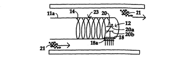
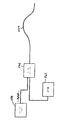
図1に示されるように、圧力検出ガイドワイヤシステム10はその遠位端部分11aにおいてセンサ12及びコイル14を有するガイドワイヤ11を含む。図5は、圧力検出共振回路を形成する柔軟先端部コイル14及び容量性センサ20の機構的配列を示す。ガイドワイヤ11は患者の心臓血管系に挿入され得る。カテーテルと称される小型の柔軟な装置は、通常、インターベンショナルカーディオロジーにおいて実施されるように、損傷または病変を有する血管の部位等へと患者の血管及び血管構造を通して挿入されたガイドワイヤ11上で誘導され得る。検出ユニット16は、患者の身体の外部においてセンサ12及びコイル14からなる共振回路の近傍に、使い捨て可能である受信器ハウジング16aを有する。通常の実施形態において、受信器ハウジング16aは、冠動脈インターベンションの場合には患者の側部においておよそ心臓の位置において取付可能なフラットコイル、特にプリントコイル、の形態を取り得るインダクタ25(図3)を坦持する。係るプリント回路コイルは好適には使い捨てである。受信器ハウジング16aは患者の皮膚表面に接触するか、または患者の体内に導入され得る。センサ12からの情報は人体(軟質組織または硬質組織)を通して受信器(検出共振回路24、図3参照)によりワイヤレスで検出される。ガイドワイヤ11の本体11bは、センサ12及びコイル14と一体化されており、インターベンショナルカーディオロジーまたはインターベンショナルラジオロジーにおいて用いられる通常のガイドワイヤ(すなわち、非腐食性の生体適合性材料(単数または複数)製)であり、患者における手術または診断のターゲット部位に達するまで血管(単数または複数)または血管構造(単数または複数)を通過するための直径、十分な可撓性、及び湾曲可能性を有し得る(図5も参照)。センサ12及び検出ユニット16は、身体的変数、特に係る部位における血圧、のワイヤレス検出を提供し、それにより、センサと先行技術に係る外部検出装置との間の機構的接続に対する必要性が排除され得る。
As shown in FIG. 1, the pressure
図2はガイドワイヤ11の遠位部分11aをより詳細に示す。遠位部分11aはガイドワイヤの遠位端において本体11bに組み込まれた円錐形状部分である。センサ12は、ワイヤ11の周囲における血圧を検出するためにガイドワイヤに取り付けられた感圧性要素18と、さらに、本明細書において感圧性容量性要素と称される可変コンデンサ20と、を含む。感圧性要素18は可変コンデンサ20に接続されるかまたは可変コンデンサ20の一部である。なお、可変コンデンサ20の静電容量値は、遠位部分11aの周囲の血液から感圧性要素18上に印加される圧力量とともに変化する。感圧性要素18は遠位ワイヤ部分11aの周囲の血液21にさらされた外側表面18aを有し、例えばバネ等により、コンデンサ20から離れる方向に付勢され得る。外側表面18a上に印加される圧力の増加または減少により、感圧性要素は、それぞれコンデンサに近づく方向にまたはコンデンサから離れる方向に移動する。この距離の変化により、コンデンサ20の静電容量値が変化し、したがって、コイル14に接続されたコンデンサ20で構成される共振回路23(図2)の共振周波数も変化する。さらに詳細には、コンデンサ20は第1プレート要素20a及び第2プレート要素20bを含み得る。ここで、第2プレート要素20bは第1プレート要素20a及びガイドワイヤ11に対して移動可能に取り付けられ、感圧性要素の動きにより第1プレート要素20aと第2プレート要素20bとの間の距離に変化が生じるよう、感圧性要素18に対して結合または同調される。例えばSensors and Actuators A: Physical Vol 73、Issues1−2、9 1999年3月、58−67ページにおいて説明されるセンサまたは本明細書の図46に示すセンサ等の、他の容量性圧力センサが用いられ得る。
FIG. 2 shows the
ガイドワイヤの遠位部分11aにおけるコイル14及びセンサ12の位置は、図1に示されるようにコイルがセンサ12よりも遠位側にあるか、または図2に示されるようにセンサ12がコイルよりも遠位側にあり得る。
The position of the
コイル14は、しばしば柔軟先端部と称される、ガイドワイヤの遠位端におけるコイル先端部(またはその部分)を利用し得るインダクタンスを提供する。このインダクタ14及び感圧コンデンサ20は血圧の変動とともに変化する共振周波数を有する共振回路23を形成する。他の実施形態において、コンデンサが固定値を有する一方で、コイルのインダクタンスは周囲の血圧に応じて変化し得る。このことは、図11A及び図11Bにおいて、または図12A及び図12Bに示されるように、周囲の血圧にしたがってコイル56またはコイル60の長さを変化させることにより達成され得る。図12A及び図12Bのアプローチにおいて、コイル60の巻線58は、長手方向または軸方向に印加される流体圧力61に応答してガイドワイヤの長手方向または軸方向に圧縮される。インダクタンスの変化は、コイルの有効巻き数を変化させることにより、または図13A及び図13Bに示されるようにコイル内部の強磁性コア66の位置を変化させることにより、周囲の血圧にも関連付けられ得る。
The
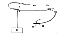
図1〜図3に示すワイヤレス圧力検出ガイドワイヤシステムの実施形態において、外部または体外の電磁場は、図3に示すようにコンデンサ26及びインダクタ(またはコイル)25を含む検出ユニット16の外部の共振(または検出器)回路24により印加される電圧に応答して形成される。共振回路23及び共振回路24の両方が同一の共振周波数に調節されると、最大エネルギー伝達が、外部回路24からガイドワイヤ11の内部に取り付けられた内部回路23へと生じるであろう。静電容量の変化(血圧変化に起因する)により回路23の同調ずれが生じると、外部回路24に伝達されるエネルギー量が変化することとなる。伝達されるエネルギーの変化を記録することにより、血圧記録が電流センサ28等を介して提供される。このように、圧力値は、近位ガイドワイヤ端部において電気接続を作ることなく、または米国特許第6,517,481号において説明されるように、検出器ユニット16への電力が切断された後に検出器ユニット16を受信専用モードに切り替えてセンサ回路12の自由振動から発せられる非常に微弱な信号に依存することなく、検出され得る。
In the embodiment of the wireless pressure sensing guidewire system shown in FIGS. 1-3, the external or extracorporeal electromagnetic field is resonant outside the
検出回路24はハウジング16a内に配置され、検出ユニット16に電子的に接続(例えばワイヤ16bを介して)され得る。それにより、電力が供給され、回路23及び回路24の動作周波数範囲内で共振回路24の周波数が変化される。電力/電流モニタ28の変化は回路23及び回路24が共振状態にあるときの共振周波数を検出する。
The
場合によっては、センサ回路23と検出回路24とのカップリングを改善するために、検出器回路24のコイル25は図14に示されるようにハウジング16aよりもむしろ挿入シース62内に配置され得る。図14の圧力検出ガイドワイヤシステムが用いられるとき、シース62は患者の大動脈内に配置され得、大動脈弓における遠位シース端部及びすべての装置(ガイドワイヤ11、バルーンカテーテル、その他)はシースを通して進められる。これはセンサ回路23と検出器回路24との間のよりよいカップリングという利点を有する。センサコイル14及び検出器コイル25が図14に示されるように同一の強磁性コアを包囲するので、ガイドワイヤ11はカップリングをさらに改善するために強磁性材料製であり得るコアワイヤを含み得る。
In some cases, to improve coupling between the
唯一のLC回路23がガイドワイヤ11において提供される。なお、このLC回路23はワイヤ11の柔軟先端部11aにおけるワイヤ巻線またはコイル14からなるインダクタンスLと、血圧とともに静電容量Cを変化させるコンデンサ20と、を含む。
Only one
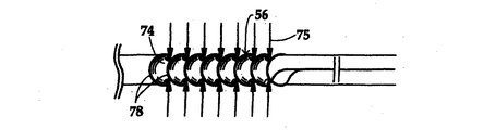
遠位圧力検出コイルまたはインダクタのインダクタンスLは、図13A及び図13Bに示されるように、血圧に応答して、共振回路72における固定値のコンデンサ70とともに接続されたガイドワイヤコイル68内で強磁性コア部材66を移動させることにより、変化され得る。代替的に、LC回路の共振周波数は可変インダクタンスコイルの有効巻き数を変化させることにより血圧に応じて変化され得る。この有効巻き数の変化は、巻線接触要素及びコイルを相互に移動させることにより、達成され得る。他の手法によれば、インダクタンスは、図12A及び図12Bにおいて示されるように、図12A及び図12Bにおいて示されるコイル60を血圧により圧縮することにより調節される。血圧により引き起こされる軸方向の力に応答してコイル60の長さを変化させることにより、コイルのインダクタンスが変化され得る。他の実施形態において、図11A及び図11Bに示されるように、コイル56を包囲する膜74は周囲の血圧75により横方向または径方向に圧縮される。コイル56の巻線78がガイドワイヤに対して移動可能に取り付けられ且つ膜74が巻線に接続された状態では、膜74の内向き方向の歪みにより、巻線78は相互に横方向またはガイドワイヤの長手方向に移動し、それにより、コイル56の有効長さが変化し、血圧変化に比例してインダクタンスが変化することとなる。
The inductance L of the distal pressure sensing coil or inductor is ferromagnetic in a
本発明のシステム10において、遠隔センサの無接点方式検出は、外部検出器回路24の電源が投入された状態にある間にセンサ回路23の共振周波数を検出することにより達成される。検出動作は、以下のようにして行われる。すなわち、外部の高周波数発振器が周波数帯の全域にわたって掃過する。異なる周波数の電磁場は外部高周波数発振器の電力消費が監視される間に生成される。検出LC回路23は、主にその共振周波数において外部高周波数発振器のRF電力の一部を吸収する。外部発振器に提供される電力は、外部回路24と検出回路23とが共振状態にあるとき、変化を示すであろう。外部高周波数発振器の電力消費におけるこの変化はLCセンサ12の共振周波数を表し、次いでこの共振周波数は血圧を示す。
In the
検出ユニット16は、いつ電力変化が生じたかを検出し、対応する血圧表示値をディスプレイに表示するための電子機器を有し得る。係る電子機器はプログラムされたコントローラまたはマイクロプロセッサ(または他の論理装置)を有し得る。なお、係るコントローラまたはマイクロプロセッサはディスプレイに出力するために、検出された共振周波数に対応する血圧を計算(またはメモリ内のテーブルを参照)する。血圧に対する共振周波数の関係は、方程式にしたがい得るか、または後の使用のために周波数を電子機器のメモリに格納された血圧に関連付ける曲線または参照用テーブルを提供するために、回路23及び回路24に対して較正され得る。例えば、監視用材料特性に対しては、Butler; Sensors and Actuators A 102 (2002年)61−66を参照されたい。血圧監視プロセスは、インターベンショナル処置の実行時に周期的にまたは必要に応じてインターベンション部位の周囲における血圧が正確に測定され得るよう、病変の血行動態における重要性を分類するために実行され得る。
The
検出ユニット16は、感圧性LC回路要素のインダクタンスまたは静電容量の変化に応答する共振回路23による少ない電磁エネルギーの吸収を検出することにより、血圧の変化を検出するよう構成される。検出ユニットは、エネルギー吸収の減少量に対応する圧力を、計算すること、またはテーブルにおいて参照すること、を実行するようプログラムされ得る。代替的に、検出ユニット16は、検出器回路24に以前の共振周波数の周辺の周波数範囲を通して走査させることにより新規の共振周波数をピックアップまたは検出し得る。次いで検出ユニット16は、新規に検出された共振周波数に関連付けられた新規の血圧を報告し得る。
The
図4A及び図4Bは、システム10のセンサ回路23に対応し且つセンサ回路23と同様の方法で機能するセンサ回路123とシステム10の検出器回路24に対応し且つ検出器回路24と同様の方法で機能する検出器回路124とを提供する、本発明の動作を示す2つの共振回路の間の共振を示す2枚の斜視図である。センサ回路123は例示目的のために上記で説明された所望の形態及び所望の構成において図示されない。検出器回路124も図示とは異なる形態であり得る。各図において、右側の回路はコンデンサ131に接続されたコイル130を有するセンサ回路123を示し、左側の回路はコンデンサ(図示せず)に接続されたコイル132を有する検出器回路124を示し、オシロスコープのリード線は検出器回路に接続される。図4Aは共振状態にあるセンサ回路及び検出器回路を示し、したがってこの周波数においてはオシロスコープのスクリーン134上に高電流が示される。係る共振回路が検出器回路にカップリングされた所望の形態及び構成にあるときの周波数発振器(図示せず)は、高電流がオシロスコープ上で観察されるまで、変化された(すなわち、2つの図示された回路が共振状態にあるときの検出器回路24の電力消費の変化から)。圧力変化(及び、したがって静電容量)を示すために、図4Bは、コンデンサ131に接続された、追加的コンデンサ132と非共振状態にあるセンサ回路を示す。なお、この非共振状態により、検出器回路における電流が低下し、したがって観察される電流はオシロスコープのスクリーン134上で、現時点では、低い値となる。検出器回路を発信させる周波数は、現時点において、LC回路23におけるコンデンサ132及びコンデンサ131とコイル130との結合静電容量により、センサ回路の新規の共振周波数とは異なる周波数である。
4A and 4B correspond to a
上記の説明から、ワイヤレス方式の圧力検出ガイドワイヤ及び検出器が提供されたことが明らかであろう。本明細書において説明された本発明に係る装置、方法、及びシステムの変化例及び修正例が、疑いなく、当業者に想起されるであろう。 From the above description, it will be apparent that a wireless pressure sensing guidewire and detector have been provided. Variations and modifications of the devices, methods, and systems according to the present invention described herein will undoubtedly occur to those skilled in the art.
図6は2接点プレッシャワイヤバージョンの構造を示す電気回路図である。遠位ワイヤ端部における共振検出回路80はワイヤレスバージョンに対して上記で説明された回路と同等である。共振周波数の変化をワイヤレスで判定することに代わり、近位ワイヤ端部86における2つの接点82及び84が利用される。
FIG. 6 is an electric circuit diagram showing the structure of a two-contact pressure wire version. The
図8は、スクリーンffr1においては約13pFの、スクリーンffr2においては約8pFの、スクリーンffr3においては約7pFの静電容量値に対する共振周波数の変化を示す。約5〜6pFの変化は、この実験における生理学的圧力変化を示し、血圧値の間違いのない検出を可能にする。図7は追加的な電気ワイヤをガイドワイヤ構造に組み込む必要性を回避するために電気導体として利用される通常のガイドワイヤ構成品を示す。なお、追加的な電気ワイヤをガイドワイヤ構造に組み込むことはワイヤの取り扱いに悪影響を及ぼし得る。市販の圧力検出ガイドワイヤの欠陥的なワイヤの取り扱いは圧力検出ガイドワイヤの広範囲な使用に対する顕著な障壁となる。図7に示されるように、ワイヤの取り扱いは、ハイポチューブ88及びコアワイヤ90という標準的なワイヤ構成品の同軸形態における2つの電気導体のみを要求することにより、非圧力検出ガイドワイヤと等しくなり得る。コアワイヤ90は、LC圧力検出回路91のコンデンサ87及びインダクタまたはコイル89に接続される。
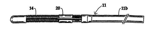
FIG. 8 shows the change in resonance frequency for a capacitance value of about 13 pF for screen ffr1, about 8 pF for screen ffr2, and about 7 pF for screen ffr3. A change of about 5-6 pF indicates a physiological pressure change in this experiment, allowing for the correct detection of blood pressure values. FIG. 7 shows a typical guidewire component that is utilized as an electrical conductor to avoid the need to incorporate additional electrical wires into the guidewire structure. It should be noted that incorporating additional electrical wires into the guide wire structure can adversely affect wire handling. The defective wire handling of commercially available pressure sensing guidewires represents a significant barrier to widespread use of pressure sensing guidewires. As shown in FIG. 7, the handling of the wire can be equivalent to a non-pressure sensing guidewire by requiring only two electrical conductors in a coaxial configuration of standard wire components, hypotube 88 and
図9は、近位ガイドワイヤ端部92がコネクタハンドルに接続される必要がないためにユーザにとってはあたかもワイヤレスであるかのように見える代替的な構成を示す。これに代えて任意のインターベンショナル処置の一部であるシース94は、ガイドワイヤ98の遠位端100が電極102を介して患者Pと電気接続状態にあり、次いで患者Pは接地電極104を介して接地電位に接続される一方で、ガイドワイヤ98の近位端92に接続するためにブラシ接点96を含む。この接地技術は、RF電極から接地まで約100オームの通常のインピーダンスを用いるRF切除手術において広範囲に利用される。図8において見られ得るように、本明細書において説明されるプレッシャワイヤの構成に対して、共振周波数は、MHz範囲の10分の1(例えばRF切除に対してKHzの範囲)である。それにより、患者の身体の容量性インピーダンスは1/fにほぼ比例するため、接地に対する直列インピーダンスは無視可能な値に低下され得る。遠位ワイヤ端部100におけるLC共振回路106は、ワイヤ98の遠位端部における電極102を通して、接地電極104を介して接地電位に接続された患者Pに接続される。共振回路106の他方端は近位ワイヤ本体98(ハイポチューブ及び/またはコアワイヤまたは固体近位ワイヤ部分)に接続される。ワイヤ98の近位端部分92は、図10に示されるように、シース内で接触ブラシ96と接触するために、絶縁されない。このことは、標準的ワイヤ構成品(ハイポチューブ及び/またはコアワイヤ)が電気導体として利用されそれにより追加的電気ワイヤの挿入が回避されるのでワイヤの取り扱いが欠陥的にならないという、2接点バージョンの場合と同一の利点を有する。
FIG. 9 shows an alternative configuration that appears to the user as if it were wireless because the proximal
他の実施形態において、図15に示されるように、外部無線送信器112とのワイヤレス方式のカップリングが達成される。外部無線送信器112のアンテナ114は図16に示されるように受信器アンテナとして機能する近位ガイドワイヤ端部116と相互作用する。アンテナを通してのカップリングを除けば、この構成は、図1に示される検出器ユニット16及びガイドワイヤ11を有するワイヤレスシステム10に関して説明されたように機能する。
In other embodiments, wireless coupling with an
さらに他の実施形態において、検出器ユニット16とガイドワイヤ11における共振回路23との間の容量性カップリングは図17に示されるように達成される。挿入シース118には1つの容量性電極として機能する特殊な金属層が装備される一方で、シースに挿入された近位ガイドワイヤ部分120は逆の電極として機能し得る。特殊な金属層の代わりに、メタリック網組の多数のシース利用がトルク能力のために利用され得る。
In yet another embodiment, capacitive coupling between the
図18に示されるように、外部または検出器共振回路32は、インターベンション部位の付近で患者に取付可能なプリント使い捨てコイル34を含み得る。コイル34は、接着層38及び着脱可能カバーシート40が提供された高分子材料製の細片36内に埋め込まれ得る。LC共振回路32のコンデンサ42は細片36内に、または細片36とは別個に、提供され得る。
As shown in FIG. 18, the external or detector
図19に示されるように、ガイドワイヤ上の共振回路は、外部流体(例えば血液)の圧力48の変化の結果として接点がコイルに対して移動し且つコイルの有効長さ50が変化し、それによりコイルのインダクタンスが変化しそれに付随して共振回路の共振周波数が変化するよう、コイル46に対して移動可能な可動電気接点44を有し得る。可動電気接点44は、外部流体圧力48の変化に応答してガイドワイヤに対して移動するプレートまたはディスク52に結合される。
As shown in FIG. 19, the resonant circuit on the guidewire causes the contacts to move relative to the coil and the
1.容量性センサを有する共振器
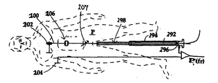
図20は、ガイドワイヤの伝導性先端部202の近位にあるガイドワイヤ298の遠位端部分200において、近傍において相互に接続された共振器206及び容量性センサ207を示す。
1. Resonator with Capacitive Sensor FIG. 20 shows a resonator 206 and a
共振器206は窒化アルミニウムまたは他のセラミック物質から作製されたセラミック要素であり、係るセラミック要素は精密発振器に使用される水晶結晶と同様の共振を生成する。しかし、水晶結晶とは対照的に、共振は一般により広く、可変静電容量を介して、より広い周波数範囲に広げることが可能である。セラミック共振器は、同様の形状因子への製造も可能であり、それにより小型の14/1000インチのガイドワイヤ内に組み込むことが可能である。セラミック共振器は機械的損傷を受けにくい傾向にある。近くに金属が存在したとしても、共振器の特性には有害な効果が及ばない。センサ207または共振器206のいずれが最遠位要素であったとしても、差異はほとんどない。能動的な供給電圧が不要であるため、ワイヤに対する接点は近位ワイヤ端部に位置する単一の簡単なピンチ接点でよい。共振器206は代替的に容量性センサ207から近位に配置され得る。
The resonator 206 is a ceramic element made from aluminum nitride or other ceramic material, which produces a resonance similar to a quartz crystal used in precision oscillators. However, in contrast to quartz crystals, resonances are generally wider and can be spread over a wider frequency range via variable capacitance. Ceramic resonators can also be manufactured to a similar form factor, which can be incorporated into a small 14/1000 inch guidewire. Ceramic resonators tend to be less susceptible to mechanical damage. Even if there is a metal nearby, there is no detrimental effect on the characteristics of the resonator. There is little difference whether either
図20では、ガイドワイヤ298は近位端部分292をシース294の内部に有するものとして示される。接点296は患者Pの外部にある近位シース部分(ハブ)内に位置する。共振回路は身体接触接地電極204を含む。
In FIG. 20, guidewire 298 is shown as having a
他の実施形態は並列共振回路である。並列共振回路では容量性センサ207は共振器206に並列に接続される。一般に、並列接続は直列接続と比べてあまり有利ではない。
Another embodiment is a parallel resonant circuit. In the parallel resonant circuit, the
さらに他の実施形態は、ガイドワイヤ内部またはガイドワイヤ上の追加的な導体ワイヤを介して共振回路をシステムに接続することである(さらなる説明については以下を参照されたい)。これにより、患者の身体を接地帰還のために使用することは不要となるが、主に外部接点が必要となるため、ワイヤの製造及び取り扱いはより難しくなり得る。送信方法は、ハイポチューブの同軸状に内部にある中心コアワイヤであってもよく、または、螺旋形式ガイドワイヤ内の2つの絶縁素線を用いる差動方式であってもよい。 Yet another embodiment is to connect the resonant circuit to the system via an additional conductor wire inside or on the guide wire (see below for further explanation). This eliminates the need for the patient's body to be used for ground return, but the manufacturing and handling of the wires can be more difficult because primarily external contacts are required. The transmission method may be a central core wire coaxially inside the hypotube, or may be a differential method using two insulated wires in a spiral guide wire.
外部システム内の電子回路はネットワーク・インピーダンス分析器のように動作する。係る電子回路はガイドワイヤ組立体全体の振幅及び位相を測定し、任意の所与の時間においてどの位置で共振が見出されるかを判定する。ワイヤに入力されるRF電流と、印加されたRF電圧と、の位相シフトは、一般的に電流の振幅におけるピークのみを測定するよりも、より正確な方法である。周波数スペクトルにおける共振の位置は局所的圧力を指示する。線形化が通常、必要となる。 The electronic circuitry in the external system operates like a network impedance analyzer. Such electronic circuitry measures the amplitude and phase of the entire guidewire assembly and determines where the resonance is found at any given time. The phase shift between the RF current input to the wire and the applied RF voltage is generally a more accurate method than measuring only the peak in current amplitude. The position of the resonance in the frequency spectrum indicates the local pressure. Linearization is usually required.
容量性センサ207に圧力が加えられると、容量性センサ207の静電容量が変化する。その結果、共振器の共振が移動される。外部システムは、ガイドワイヤに入力されるRF電流を位相、振幅、またはその両方に関して監視することにより、係る共振の移動を検出することができる。
When pressure is applied to the
2.直接的圧力検出のためのMEMS共振器
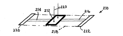
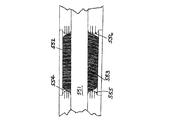
図21及び図22はセンサ210を示し、センサ210は図20に示すセンサと同じ物質で作製されたものである。しかしセンサ210は、より長く、1つまたはいくつかの小型音叉のように動作する。この事例では、加速度計として使用されるためのSandia National Laboratories(Olsson,2012年12月)により提案されるものと同様の2つの音叉の形態が示される。
2. MEMS resonator for direct pressure detection FIGS. 21 and 22 show a
本発明はMEMS(微小電気機械システム)センサ210を加速度計(質量が側方に加速すると、一方の音叉が伸張し、他方の音叉が収縮する)として使用することを意図するものではない。これに代えてセンサ210は、2つのセラミック音叉214、216を共に保持する中心プレート212に印加される圧力を測定するよう設計されたものである。セラミックと患者の血液とが接触することを防止するために、膜218が提供される。2つの電極または接点220、222は、ガイドワイヤ298に対する導電性接続を提供する。
The present invention is not intended to use the MEMS (microelectromechanical system)
共振は、上述と同一の方法により、外的に測定が可能である。係る共振器210が使用される場合、コンデンサ、インダクタ、または他のいかなる構成要素もガイドワイヤ298において不要である。これにより、ガイドワイヤを製造する際の複雑性及び費用が顕著に軽減される。
Resonance can be measured externally by the same method as described above. If such a
圧力223が増加すると中心プレート212がより下方に押され、それにより、音叉共振器214、216は引かれて、伸張される。その結果、これらの共振器の共振周波数がシフトし、係るシフトは外部システムにより検出することが可能である。共振器210は、ガイドワイヤ298の絶縁部分から周囲の血液までの大きな寄生容量により共振の検出が過度に弱められることがないよう、インピーダンスは適度に低い値であることが必要である。
As the
他の実施形態は、ガイドワイヤ内部のまたはガイドワイヤ上の追加的な導体ワイヤを介してMEMSセンサをシステムに接続することである(詳細については後に議論する)。これにより、患者の身体を接地帰還のために使用することは不要となるが、ワイヤの製造及び取り扱いはより難しくなり得る。送信方法は、ハイポチューブ内部の同軸中心ワイヤであってもよく、または、螺旋形式ガイドワイヤ内の2つの絶縁素線を用いる差動方式であってもよい。 Another embodiment is to connect the MEMS sensor to the system via additional conductor wires inside or on the guide wire (details will be discussed later). This eliminates the need to use the patient's body for ground return, but can make wires more difficult to manufacture and handle. The transmission method may be a coaxial center wire inside the hypotube, or a differential method using two insulated wires in a spiral guide wire.
3.セラミック圧力検出
図23は複数の容量性プレート226(典型的にはニッケル製)を有するサンドイッチされたセラミック構造224を示す。セラミック構造224は、銅製終端器232、234を有する2つの伝導性エポキシ・パネル228、230の間で交互配置されたアレイ状に構成されて、多層セラミックコンデンサまたはMLCCが形成される。係る多層セラミックコンデンサ224はAVX/Kyoceraにより製造される。一般的なセラミック物質はチタン酸バリウムである。多数の係るコンデンサはマイクロホニック雑音を有するという望ましくない副作用を有する。AC電圧にさらされると、係るコンデンサは可聴雑音を放出し得る。この効果は相互交換性であるため、外部圧力波236により静電容量が変化し、AC電圧が発生する可能性もある。この静電容量変化または電圧は、静電容量が十分に大きいときには誘導性素子がコンデンサから遠位(例えば検出器システム内のガイドワイヤの外部)に配置され得るならば、多数の方法(例えば直接的には、生成されたAC信号として、または間接的には、共振回路内のコンデンサ224を使用することにより)で電子機器による検出が可能である。
3. Ceramic Pressure Sensing FIG. 23 shows a sandwiched
携帯電話などの小型化電子機器の普及により、これらのセラミック構造がより小型の、より高い静電容量の変化体で利用可能となりつつあり、産業上の目的は、単位体積あたりの静電容量の密度を高めることである。したがって層の個数は増加しつつある。現在のICの供給電圧の値がさらに低下し、したがってコンデンサの降伏電圧定格がより小さくなることが要求されるという事実は、この傾向を支援する。このことは、本発明に対して有利である。なぜなら、それにより圧力により誘導される容量変化信号のソース・インピーダンスが低減され、この唯一の容量性要素のみがガイドワイヤ内でセンサとして必要となる確率が大きくなるためである。信号は図1〜図19を参照して上述したのと同一の方法を使用して抽出することが可能である。電子システムは静電容量、生成された信号、またはその両方を測定することが可能である。 With the widespread use of miniaturized electronic devices such as mobile phones, these ceramic structures are becoming available in smaller, higher capacitance variants, and the industrial objective is to increase the capacitance per unit volume. It is to increase the density. Therefore, the number of layers is increasing. The fact that current IC supply voltage values are further reduced and therefore require that the capacitor breakdown voltage rating be smaller, supports this trend. This is advantageous for the present invention. This is because it reduces the source impedance of the capacitive change signal induced by pressure and increases the probability that only this single capacitive element will be needed as a sensor in the guidewire. The signal can be extracted using the same method as described above with reference to FIGS. The electronic system can measure capacitance, the signal generated, or both.
多層セラミックコンデンサ(MLCC)224が図10〜図19を参照して上記で開示したガイドワイヤにより担持される圧力測定LC回路において使用される場合、MLCC224は好適には非常に高密度のMLCCであり、したがって高い静電容量を有する。係る高い静電容量は、大きいインダクタンスを必要とする。大きいインダクタンスを小さいガイドワイヤに組み込むことは、たとえ不可能ではないにせよ困難となる。1つの解決策は、インダクタンスの大部分を分割してガイドワイヤの外部に配置することである。この同一の設計は、ガイドワイヤの遠位端において部分的に配置される必要があるインダクタンスを有する任意のガイドワイヤに搭載された回路において使用され得る。
When a multilayer ceramic capacitor (MLCC) 224 is used in the pressure measurement LC circuit carried by the guidewire disclosed above with reference to FIGS. 10-19, the
4.FFR電子システム
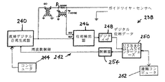
図24は、共振器206、210内の、及びインダクタ・コンデンサ・ベースのFFRガイドワイヤ(図1〜図19)内の共振を検出するのに好適な電子システム238の一実施形態を示す。以下の説明では、図20及び図22のガイドワイヤシステムに特に言及する。重要な構成要素のみが図示され、電源供給装置またはコンピュータ・アルゴリズムなどの支持的機能は当業者に周知である。
4). FFR Electronic System FIG. 24 illustrates one embodiment of an
制御可能なRF生成器240は固定周波数のRF信号をガイドワイヤ298に送信し、検出回路242は、発振器出力とワイヤが引き出した電流との間の位相シフトを測定する。生成器240はアナログ・システムまたはデジタル・システムを介して制御が可能な任意の種類であってよい。位相ロック・ループ(PLL:phase−locked loop)は以前は一般的であったが、周波数のより高速な制御のために、直接デジタル合成(DDS:direct digital synthesis)が、より現代的な方法となった。電流はRSENSEにおいて検出され、安全な分離目的のために変成器TSENSEを介して送信される。
コンピュータ244は、ガイドワイヤ298における共振よりも低いことが保証された特定の周波数に移動するよう、制御可能な生成器240に命令する。コンピュータ244は次に、生成器出力と、RSENSEで取り出された電流検出信号と、の間の望ましい位相シフトが達成されるまで、その周波数を漸次増加させるよう、生成器240に命令する。この位相シフトは、ガイドワイヤからその周囲への様々な漏洩静電容量における容量ドリフトが補償されるよう、後に再び調節され得る。
The
位相検出器246は位相シフトを測定し、そのアナログ出力は変換器またはデジタイザ248によりデジタル化される。位相値は圧力とともに移動するが、その移動は線形関係ではない。2方向ユニバーサル・シリアル・バス(USB)またはローカル・エリア・ネットワーク(LAN)インターフェース250はコンピュータ252(所望によりコンピュータ244と同一)と通信する。コンピュータ252はインターフェース250及び制御器254を介してコンピュータ244の機能を実行し得る。コンピュータ252は位相信号を圧力について線形化し、圧力をローリンググラフまたは任意の他の所望の形式で表示する。LANインターフェース250は、コンピュータ252を電気的に分離する他にもコンピュータ252を遠隔位置(例えば、しばしば病院内の2つのカテーテル検査室の間に存在し得る共有制御室)に配置することを可能にするため、有利であり得る。かくして既存の病院インフラストラクチャをデータ転送のために使用することが可能となる。データの帯域幅は他の通常の活動と比較して、非常に低い5kbit/秒未満の値となる。
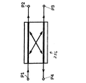
電子機器の他の実施形態では、方向性結合器256(図26)を使用することにより、振幅のみが測定される。これは、非常に狭い周波数応答を有する共振器を使用する場合、十分であり得る。方向性結合器256は、受信または入力ポートP1において、固定周波数生成器(例えば直接デジタル合成型)に接続される。送信または出力ポートP2において、方向性結合器256は共振器(図20及び図22に示す)を含むガイドワイヤに接続される。分離ポートP4において、方向性結合器256は振幅変化を監視するために信号処理コンピュータに接続される。方向性結合器256の他のポートP3はこの用途では未使用である。接地帰還はすべてのポートに対して共通である。
In other embodiments of the electronics, only the amplitude is measured by using a directional coupler 256 (FIG. 26). This may be sufficient when using a resonator with a very narrow frequency response.
電子機器のさらに他の実施形態(図27)は時間領域で動作する。ここでは、バーストのみを送信するパルス発振器258が使用される。次にシステムの受信器260はガイドワイヤ(264)内の共振回路からのリンギングを聴き取る。この方法は、上記の連続的波方法に関する干渉の懸念が存在する場合、明らかに有益であり得る。共振が好適な周波数であれば、バースト発振器258はライセンスフリーの産業科学医療用(ISM:industrial−scientific−medical)バンドで動作し得る。図8は、送信/受信器・スイッチ262を介してガイドワイヤ264に交代的に接続可能なバースト・パルス生成器258及び受信器/処理回路260を示す。
Yet another embodiment of the electronic device (FIG. 27) operates in the time domain. Here, a
図25に示すさらなる電子処理システム266は、コーティングが施されたガイドワイヤと、患者または対象の身体と、の間で自然に発生する漏洩静電容量の変化を補償する。これらの静電容量は、ワイヤが前後に移動されるかまたは押されたとき、変化する。
A further
処理システム266の第一部268は、図24の実施形態におけるように、圧力を検出する位相検出回路である。位相検出回路268は、図24に示す構成要素と同一の構成要素を有し、同一の参照番号を有する。処理回路部分268は第2回路部分270の周波数よりも遥かに低い周波数で動作され、第2部分270において使用される周波数に対しては反応しないよう設計される。ワイヤが動くと、ガイドワイヤ272において漏洩静電容量CLEAKが変化し、その結果、圧力変化の表示は誤ったものとなる。2つの部分のスペクトル感度を設定するフィルタは図面から簡略化のために省略されており、係るフィルタは実質的に単なるLCフィルタであるため、当業者により容易に設計され得る。位相シフタ274、274′が必要である。なぜなら大部分の通常の位相検出回路は180度ごとに不明確になり、180度及び180度の整数倍に過剰に近接して動作された場合、不正確となるためである。
The
図25における第2または上方回路部分270は、図24の回路のそれぞれの構成要素に類似する構成要素を有し、主要な記号と同一の参照番号を有する。回路部分270は、AMラジオ帯からの雑音を避けるために、遥かに高い周波数(通常は1.6MHzを越える)で動作する。ガイドワイヤ272内のインダクタLWIREのために、第2回路部分270は、漏洩静電容量CLEAKのみに対して高い感度を示すが、圧力測定静電容量CSENSORに対しては感度を示さない。したがって上方または回路部分270において収集される位相情報は漏洩静電容量CLEAKを示す。この情報は次に、漏洩静電容量CLEAKの変化により生じた虚偽圧力変化情報の量を補償するために、システム・ソフトウェアにおいて使用され得る。これにより、漏洩静電容量CLEAKの変化に起因する圧力測定の変化が実質的に中和され、ワイヤの移動が冠血流予備量比を測定する日常的な手順の一部である医療環境においてシステムの圧力読み出し確度が大いに改善される。
The second or
計算のオーバーヘッド及びデータ速度が低いため、ハンドヘルド型装置(例えばスマートフォンまたはタブレット・コンピュータなど)を使用することも可能となる。通常のデジタル音声データ・チャネル(セル・ネットワーク)を通るデータ送信でさえも実現可能である。この技術を戦場での使用などの他の目的のために考えるならば、これは他の選択肢を可能となる。 Due to the low computational overhead and data rate, it is also possible to use handheld devices (eg smart phones or tablet computers). Even data transmission over a normal digital voice data channel (cell network) is feasible. If this technology is considered for other purposes such as battlefield use, this would allow other options.
図28に示すように、容量性圧力検出ガイドワイヤ500はガイドワイヤ・コアワイヤ501を有し、ガイドワイヤ・コアワイヤ501は管状容量性センサ510と、遠位端部分に配置されたコイル512と、を有する。円筒形形状のセンサ510は内側センサ電極としてコアワイヤ501を利用する。内部が金属化された管状ポリマー部材502は外側電極及び圧力検出膜として機能する。好適にはこの管状ポリマー膜502は、圧力が印加された場合に円筒が楕円形状または卵形形状を取ることが可能となるよう、可変の壁厚さを有する。このようにして、圧力変化に対するセンサ510の感度は向上することとなる。内側電極またはコアワイヤ501と管状外側電極502との間に電解質503が配置される。空隙504が存在することにより、電解質503と外側電極502及び内側電極501との間の接触面積は、外部電極502において印加される圧力に応じて変化することが可能となる。電解質503及び空隙504は、1対のポリマー・スペーサ・リング514、516により、密閉または閉ざされる。ガイドワイヤ500は、最初に接点ハンドルを近位ワイヤ部分から取り外す必要なしに、インターベンショナルカーディオロジーにおいて通常実施されるように血管及び血管構造を通して患者または対象の身体(例えば損傷または病変を有する血管の部位など)に挿入され得る。カテーテルは患者の身体内でガイドワイヤ上で案内され得る。
As shown in FIG. 28, the capacitive pressure sensing guidewire 500 has a
図28にさらに図示されるように、コイルまたはインダクタ512にはフェライト・コア518が提供され、コアワイヤ501の分離された部分の間に配置される。コイル512はコネクタ520、522によりコアワイヤ501のこれらの部分に電気的に接続される。ガイドワイヤ500の遠位先端部524はポリマー・コーティング526を有し、ポリマー・コーティング526は、遠位先端部の全周囲において伝導性のために金属化される。遠位先端部524は従来のインターベンショナル・ガイドワイヤと同一構成を有し、柔軟コイル構造528を含む。
As further illustrated in FIG. 28, the coil or
金属化された内径を有する管状ポリマー部材502は、一定角度で切断され、パッドのように電気的結合が容易となる。遠位側におけるコイルがRO用となるよう、ガイドワイヤ501は、少なくともコイル512と容量性センサ510との間にポリマー・コーティング530が提供される。外側接続532は、コイル512上に配置されたカプトン・チューブであり、コアワイヤ501に接合され得る。
The
図29は、ガイドワイヤ500の遠位部分に対して異なる構成を有する容量性センサ540を示す。ここで、容量性センサ540は、円錐形状部分548を有し且つセンサの内側電極を形成するコアワイヤ541を含む。外側電極542は、周囲の血圧下で変形しないように形状が実質的に固定された管状部材である。感圧性膜545が、センサ540の遠位端部または前方端部において横断または断面様式で取り付けられる。圧力546が感圧性膜545に印加されると、感圧成膜545が変形し、それにより電解質543により占められる体積が変更される。静電容量は、電解質/電極接触面積の変化により変化し、空気体積544を様々に圧縮する。容量変化は、体積の移動に対して表面変化(電解質/電極)をより大きくする内側電極541の円錐形状部分548により、増大化される。
FIG. 29 shows a capacitive sensor 540 having a different configuration with respect to the distal portion of the guidewire 500. Here, the capacitive sensor 540 includes a
ガイドワイヤ500の遠位部分におけるコイル512及びセンサ510または540の位置は、図28に示す状態(コイル512はセンサよりも近位にある)であってもよく、または、その逆の位置関係でもよい。
The position of
図30は、等尺性のコアワイヤ551を有する、さらに異なるコンデンサ構成550を示す。圧力検出膜555、556が、円筒形コンデンサ550の近位及び遠位に取り付けられる。これらの膜555、556は、周辺の血圧の大きさに応じて可変的に変形され、それにより、(1つまたは複数の空洞域554に対して)電解質体積553が変化し、電解質553と電極552との間の接触面積が変化する。内側表面に沿って金属化された外側管状電極552は、周囲圧力の変化に応答してその構成を変化させることはない。
FIG. 30 shows yet another capacitor configuration 550 having an
さらに他の実施形態では、外側電極と、ガイドワイヤ・コアワイヤにより形成される内側電極と、の間の空間は、100ミクロンの直径またはそれ以下に最小限にされ、電解質は、コンデンサに対して近位または遠位(または代替的にその両方)にある、感圧性体積部分に主に格納される。感圧性槽(単数または複数)が圧縮されると、コンデンサの外側電極と内側電極との間の空間に電解質が移動することができるよう、感圧性体積はコンデンサに接続される。この構造により、図29の構成と比較して、さらにより大きい感度が可能となる。 In still other embodiments, the space between the outer electrode and the inner electrode formed by the guidewire core wire is minimized to a diameter of 100 microns or less and the electrolyte is close to the capacitor. It is mainly stored in a pressure sensitive volume that is in position or distal (or alternatively both). When the pressure sensitive tank (s) are compressed, the pressure sensitive volume is connected to the capacitor so that the electrolyte can move into the space between the outer and inner electrodes of the capacitor. This structure allows even greater sensitivity compared to the configuration of FIG.
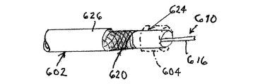
図31を参照すると、本発明は、ガイドワイヤ601を含む。ガイドワイヤ601はその遠位端部分に、容量性センサ612及びコイル614からなる共振回路610を有する。共振回路610は伝導性先端部または接地電極603に接続され、この接地電極603は、共振回路と患者の血流とを電気的に接続する。血流を通して、シースまたはガイドカテーテル602の遠位部分に取り付けられた他の接地電極604に対する接続が作製される。本発明のこの実施形態では、血液経路が病変箇所に応じて約5〜20cmの比較的短い長さからなるため、及び血液が組織よりも優れた導体であるため、接地電極603と接地電極604との間の抵抗は最小化される。外部接地電極を有する手法と比較して電気抵抗が最小化される他にも、この手法では、外部接地電極を患者に取り付ける必要がないという利便性がもたらされる。それにより、手順の容易化及び迅速化が図られる。最後に述べるが決して軽んずべきでないことであるが、この手法では、心臓などの重要臓器を伝導性経路の一部として有することなく、患者の血流を通る接続が短いという利点がもたらされる。このことは、米国特許出願公開第2001/0051769(A1)号及び米国特許第7,645,233(B2)号に記載されるようにセンサが能動的に電力供給される手法では、特に問題となる。異なる実施形態では、遠位シースまたはガイドカテーテル端部における接地電極(604)は、シースまたはガイドカテーテル(602)に挿入される可撓性チューブの遠位端上に取り付けられ得る。これは明らかに、ユーザが好む任意種類のシースまたはガイドカテーテルが利用可能であるという利点を有する。
Referring to FIG. 31, the present invention includes a
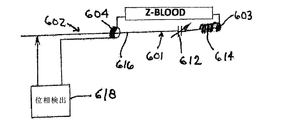
図35は、接地電極603と接地電極604との間に配置された回路経路Z−Bloodと、一方の側部においてガイドワイヤ601のコアワイヤ616に接続され且つ他方の側部において遠位ガイドワイヤ接地電極604(シースもしくはガイドカテーテル上に、またはガイドもしくはシースに挿入されるチューブ上に、遠位に取り付けられる)に接続された共振回路610と、からなるシステム全体の電気的接続を示す。位相検出システム618は、ガイドカテーテルまたはシース602の遠位接地電極604と、ガイドワイヤ601のコアワイヤ616と、に接続され、図20〜図27を参照して上記で詳述されている。
FIG. 35 shows a circuit path Z-Blood disposed between the
図33は、シースまたはガイドカテーテル602の近位端またはハブにおいてブラシ接点606を通してガイドワイヤ601のコアワイヤ616をFFR(冠血流予備量比)システムに接続する1つの方法を示す。ブラシ接点606は、シースまたはガイドカテーテル602のハブに差し込まれるよう設計された止め具または連結器605の一部である。リードまたはワイヤ617は、止め具または連結器605からFFRシステムまで延びる。液体導管またはチューブ619は、近位の圧力センサに対して流体の流れを伝導するためにハブ622まで延びる。
FIG. 33 illustrates one method of connecting the
代替的にブラシ接点606はハブに一体化されてもよい。さらに他の実施形態ではブラシ接点は、ガイドまたはシース602に挿入されるチューブに近位に取り付けられてもよい。
Alternatively, the
図34では、FFRシステムに対する電気的接続がガイドワイヤ601のコアワイヤ616の近位端に取り付けられたワイヤ・トルカ607を通してなされる異なる実施形態が示される。
In FIG. 34, a different embodiment is shown in which the electrical connection to the FFR system is made through a
図32では他の実施形態が示され、この実施形態ではガイドワイヤ601のコアワイヤ616がシースまたはガイドカテーテル602に電気的に接続される。この場合、連結は、一方のコンデンサ電極としてのステンレス鋼網組620と、他方のコンデンサ電極としてのガイドワイヤ601のコアワイヤ616と、の間で容量的に達成される。網組620は、ポリテトラフルオロエチレンまたは他のポリマー物質の内側層624と、柔らかいナイロンまたは同様のポリマー物質の外側層626と、の間に挟まれる。2つの相互に絶縁された導体(図示せず)が、シースまたはガイドカテーテル602に沿ってFFRシステムまで、血液電極604から、及びステンレス鋼網組620から、それぞれ延びる。シースまたはガイド602の網組620を利用することに代えて、金属化されたチューブ(図示せず)が、ガイドワイヤ601のコアワイヤ616に対して逆の電極を作るために挿入されてもよい。
FIG. 32 shows another embodiment in which the
ガイドワイヤ601は、インターベンショナルカーディオロジーにおいて通常実施されるように、患者の身体内において、例えば血管及び血管構造を通って損傷または病変を有する血管の部位へと挿入され得る。カテーテルは、挿入されるよう、ガイドワイヤ上で前進され得る。図32からの容量性カップリングの手法、及び図33に示すシースブラシ接点606は、近位ガイドワイヤ端部から電気的接点ハンドルを分離する必要なしに、カテーテルの挿入を可能にする。これにより、FFR測定をインターベンショナル処置にシームレスにフィットさせることが可能となる。
ガイドワイヤ601の遠位部分におけるコイル614及び容量性センサ612の位置は、図31に示す状態(コイル614がセンサ612よりも近位にある)であってもよく、または、その逆の位置関係でもよい。コイル614は、しばしば柔軟先端部(図28、528)と呼ばれるガイドワイヤ601の遠位端におけるコイル先端部(またはその部分)を利用し得るインダクタンスを提供する。このインダクタ614及び感圧コンデンサ612は、血圧変動に応じて変化する共振周波数を有する共振回路610を作る。図28〜図30を参照して上述したように、通常の真空または空気充填がされたコンデンサは、身体組織により提示される負荷を駆動することができない。通常の14/1000ガイドワイヤの最小寸法要件を満足し、且つ身体及びコアワイヤの伝導を通して検出可能な十分に大きい容量変化を提供するために、電解質コンデンサ510、540、550が利用される。他の実施形態では、コンデンサ612は固定値であってもよく、その一方でコイル614のインダクタンスは、図1〜図19を参照して上述したように周囲の血圧に応じて変化する。さらに他の実施形態では、共振回路610は、図20〜図27を参照して上述したように周囲の血圧に応じて共振周波数が変化するセラミック共振器206により、置換されてもよい。
The position of the
血圧監視プロセスは、インターベンショナル処置の実行時に周期的にまたは必要に応じてインターベンション部位の周囲における血圧が正確に測定され得るよう、病変の血行動態における重要性を分類するために実行され得る。 The blood pressure monitoring process can be performed to classify the importance of the lesion in hemodynamics so that blood pressure around the intervention site can be accurately measured periodically or as needed when performing an interventional procedure. .
図31〜図36の上記の説明から、半ワイヤレス方式の圧力検出ガイドワイヤ及び検出器が提供されたことが明らかとなろう。本明細書において説明された本発明に係る装置、方法、及びシステムの変化例及び修正例が、疑いなく、当業者に想起される。 It will be apparent from the above description of FIGS. 31-36 that a semi-wireless pressure sensing guidewire and detector have been provided. Variations and modifications of the devices, methods, and systems according to the invention described herein will undoubtedly occur to those skilled in the art.
図31は、通常のガイドワイヤ構成要素を電気導体として利用することにより、ワイヤの取り扱いに悪影響を及ぼす追加的な電気ワイヤをガイドワイヤ構造に組み込む必要性が回避されることを示す。市販の圧力検出ガイドワイヤの欠陥的なワイヤの取り扱いは圧力検出ガイドワイヤの広範囲な使用に対する顕著な障壁となる。図31に示されるように、ワイヤの取り扱いは、ただ2つの電気導体のみを要求すること、すなわち標準的なワイヤ構成要素である、コアワイヤ、及び遠位先端部を利用することにより、非圧力検出ガイドワイヤと等しくなり得る。 FIG. 31 illustrates that utilizing a normal guidewire component as an electrical conductor avoids the need to incorporate additional electrical wires into the guidewire structure that adversely affect wire handling. The defective wire handling of commercially available pressure sensing guidewires represents a significant barrier to widespread use of pressure sensing guidewires. As shown in FIG. 31, the handling of the wire requires only two electrical conductors, i.e., by utilizing a standard wire component, a core wire, and a distal tip. Can be equal to guide wire.
図35は、近位ガイドワイヤ端部がコネクタハンドルに接続される必要がないためにユーザにとってはあたかもワイヤレスであるかのように見える電気的な構成を示す。これに代えて、任意のインターベンショナル処置の一部であるシースまたはガイドカテーテル602は、ワイヤ616の近位端に接続するために図33に示すブラシ接点606を含み、その一方で、ワイヤの遠位端は、図31に示すようにシースまたはガイドカテーテル602の遠位端に取り付けられた接地電極604を通して接地電位に接続された患者と電気的に接触する。外部パッチ電極接地技術は、RF電極から接地までの通常のインピーダンスが約100オームであるRF切除手術において広く利用される。共振回路610の他方端はワイヤ本体またはコアワイヤ616に接続される。ワイヤ616の近位端部分は、図33に示されるように、シース602内で接触ブラシ606と接触するために、絶縁されない。これは、標準的なワイヤ構成要素(コアワイヤ及び遠位先端部)が電気導体として利用され、追加的な電気ワイヤの挿入が回避されるため、ワイヤの取り扱いが損なわれないという利点を有する。
FIG. 35 shows an electrical configuration that appears to the user as if it were wireless because the proximal guidewire end need not be connected to the connector handle. Alternatively, the sheath or guide
図36ではさらに他の実施形態が示される。この実施形態では、シースまたはガイド602内の流体柱と接触し、それにより患者の血流と接触するために、シースまたはガイドハブ622に挿入された伝導性円筒またはチューブ608を通して接地接続が確立される。図31に示す手法と比較すると、これは、シース602が永久的接地電極(604)により変更される必要がないという利点を有する。円筒またはチューブ608は、近位ワイヤ端部上でシース622のハブまたはガイドカテーテル602へと前進される伝導性円筒形チューブであってもよく、または円筒がガイドワイヤの周りで開閉が可能となるよう2つのリンクされた半体シェルから構成されてもよい。いずれの場合においても、円筒またはチューブ608は、ワイヤ628を通してFFRシステムの接地端子に接続される。図36では、一方の側ではガイドワイヤ・コアワイヤ616に電気的に接続され、且つ他方の側ではワイヤ632を介してFFRシステムに電気的に接続された、ワイヤ・トルク630による連結も図示される。
FIG. 36 shows still another embodiment. In this embodiment, a ground connection is established through a conductive cylinder or
図37に示すように本発明は、その遠位端部分において容量性センサ906(図38)を有するガイドワイヤ900を含む。容量性センサ906は、容量性センサを患者の血流に電気的に接続する伝導性先端部または接地電極902に接続される。血流を通して、患者に取り付けられた外部接地電極904に対する接続が作製される。センサの近位において、ガイドワイヤは絶縁性物質の薄層またはコーティングにより身体から電気的に絶縁される。本発明のこの実施形態では、接地電極902と接地電極904との間のインピーダンスは30オーム未満のオーダーである。数百オームまでの値が本発明に対して許容され、そのため、切除手術において使用されるよりも小型のパッチ電極が実現可能である。この直列インピーダンスは、米国特許出願公開第2001/0051769(A1)号及び米国特許第7,645,233(B2)号において記載されるようなセンサ906が能動的に電力供給される手法では問題となり得るが、本発明では懸念の必要はない。他の重大な寄生要因はワイヤ/身体(血液)インピーダンスである。容量性センサ906は寄生ワイヤ/身体インピーダンスよりも1オーダー高い静電容量を有する必要がある。図39から見られるように、このことは、300〜400pF範囲のワイヤ/身体静電容量を用いて生体内で成り立つことが確認された。30pFのオーダーのワイヤの動きを有する寄生容量の変化(図39の中央の軌跡を参照されたい)も、センサがnF範囲の容量変化を生じるかぎり、懸念の必要はない。図40では、寄生容量に対する心拍及び呼吸の影響が示される。この変化例はpF範囲内であり、再び、容量変化がnF範囲内にあるかぎり、圧力測定に影響を及ぼさない。図37では、接地電極902と接地電極904との間に配置された血液−身体回路経路Z−Blood/Bodyと、一方の側部においてガイドワイヤ900のコアワイヤに接続され且つ他方の側部において遠位ガイドワイヤ接地電極902に接続された容量性センサ906と、からなるシステム全体の電気的接続を示す。位相検出回路構成要素908は、外部患者接地電極904に接続され、且つ、接点996を通してガイドカテーテルまたはシース994に、またはガイドワイヤ900の近位コアワイヤ996と直接的に、接続される。
As shown in FIG. 37, the present invention includes a
位相検出回路908は、容量変化を検出するために、ネットワーク・インピーダンス分析器と実質的に同様に動作する。位相検出回路908は位相及び振幅を非常に高速なシーケンス(通常は毎秒100回以上)で測定する。従来のインピーダンス分析器とは対照的に、位相検出回路908は関心対象の周波数スペクトル全体を、掃過ではなく同時に、通常は2kHz〜10kHzで測定する。位相検出回路908は複素高速フーリエ変換(FFT:Fast Fourier Transform)方法または同様の計算を使用する。
図42は、心臓及び呼吸サイクルに関するインピーダンス変化を示し、位相測定ではなく振幅測定である。これは2つの目的のために有用である。システムは、インピーダンスの変化が表示される圧力値に対して最も影響が少ない周波数を自動的に見出さなければならず、この振幅信号を監視することは、システムが必要に応じてこれを実行することを可能にする。加えてこの信号は、例えば緊急看護の際に他の好適な装備が存在しないときに、バイタルサインの基本的な監視を可能にする。 FIG. 42 shows the impedance change for the heart and respiratory cycle and is an amplitude measurement rather than a phase measurement. This is useful for two purposes. The system must automatically find the frequency at which the change in impedance has the least effect on the displayed pressure value, and monitoring this amplitude signal is done by the system as needed. Enable. In addition, this signal enables basic monitoring of vital signs when no other suitable equipment is present, for example during emergency care.
ガイドワイヤ900は患者の身体内に挿入され得る。カテーテルは、通常、インターベンショナルカーディオロジーにおいて実施されるように、血管及び血管構造を通して患者の身体内に挿入されたガイドワイヤ900上で、例えば損傷または病変を有する血管の部位へと案内され得る。図37に示すシースブラシ接点996は、近位ガイドワイヤ端部から電気的接点ハンドルを取り外す必要なしにカテーテルを挿入することを可能にする。これにより、FFR測定をインターベンショナル処置にシームレスにフィットさせることが可能となる。代替的に、クリップ接点は近位ワイヤ端部に対する取り外し及び取り付けが容易である。ガイドワイヤ・トルク調節ハンドルは日常的に使用され、これらは同時に近位電気ワイヤ接点を提供するために用いられ得る。
ガイドワイヤ900の遠位部分における容量性センサ906の位置は、図38に示すようにセンサがガイドワイヤのコイル部分(柔軟先端部と呼ばれることが多い)に配置された状態であってよい。容量変化がpF範囲内にある通常の真空または空気が充填されたコンデンサは、身体組織により提示される負荷を駆動することができない。通常の14/1000ガイドワイヤの最小寸法要件を満足し、且つ身体及びコアワイヤの伝導を通して検出可能な十分に大きい容量変化を提供するために、本明細書で図28〜図30を参照して上述したコンデンサ510、540、または550などの電解質含有コンデンサが利用される。
The position of the
図43〜図46に示されるように、容量性センサ906を実装するためのMEMSセンサ702、または代替的に、本明細書で開示される任意の可変静電容量の容量性センサは、並列に接続された0.2×0.2×1.2mm(幅、深さ、長さ)の代表的な寸法及び0.5〜5nFの静電容量範囲を有する2つのコンデンサ704、706を含む。一定期間にわたり生成された改善された誘電体は静電容量範囲がさらに高くなり得る。コンデンサ704(図46)の、イオン注入された電極の形体の2枚のプレート708及び710(図47)は、特定的な空気または真空間隙712により離間され、コンデンサ704の一方のプレートは固定状態に保持される(下部プレート710)一方、他方のプレートは圧力が印加されると湾曲する(上部プレート708)。2枚のプレートの間には、空気間隙712(空気、真空、または理想気体)と、高い誘電率(2000〜15000以上)を有する誘電体714と、が配置される。誘電体714はBaTiO3、CaCu3Ti4O12、または同様の物質であってよい。圧力が印加されると、上部プレート708は空気間隙712を通して湾曲し、最終的に誘電体層714と接触する。上部プレート708が誘電体714と接触すると、コンデンサ704は電源がオンになる。圧力増加にともない、上部プレート708と誘電体714との接触面積が大きくなる。誘電体714の目的は、上部電極708と下部電極750との間で達成可能な静電容量を顕著に増大化することである。上部プレートと誘電体とが接触する以前の静電容量は無視可能である。静電容量と誘電体との関係は以下の式により提供される。
静電容量=(er*e*A)Ih
式中、eは誘電率、erは誘電定数、Aはプレート面積、及びhはプレート間の距離である。この装置の最小圧力範囲は上部プレート708と誘電体層714との間の最小接触面積により指定される。最大静電容量は飽和圧力が到達され且つ最大接触面積が達成されたときに定められる値である。上部プレート708と誘電体層714との間の接触面積の変化に応じて静電容量が変化し、静電容量のこの変化は加えられている圧力に比例する。この物理現象は第2コンデンサ706に対しても同一である。
43-46,
Capacitance = (er * e * A) Ih
Where e is the dielectric constant, er is the dielectric constant, A is the plate area, and h is the distance between the plates. The minimum pressure range for this device is specified by the minimum contact area between the
上部プレート708及び下部プレート710の電極は、ドーピングが施されたシリコン、白金、または他の好適な金属により作製され得る。上部プレート708は、ダイヤフラム(0.7〜3ミクロンの厚さ)をSOI(シリコン・オン・インシュレータ)ウェーハの膜にエッチングする反応イオンエッチング(RIE:reactive ion etch)処理を使用して製作される。結果的に生成されるスタンドオフにより2枚のプレートは分離され、上部プレート電極708と誘電体層714との間に間隙712が画成される。スタンドオフを作る代替的な方法は、酸化物層を堆積または成長させ、フォト・リソグラフィー及びエッチング手段を介して酸化物層をパターン形成することである。SOIウェーハのハンドル部分は、センサ製作の間の取り扱いの堅牢性を改善するために存在し、厚さが100ミクロンより大きいが、好適な実施形態では約300ミクロンの厚さである。下部プレート710及び誘電体層714はバルクまたはSOIシリコン・ウェーハ716上に配置される。下部プレート電極710はシリコン・ウェーハにドーピングすることにより、または白金もしくは他の好適な金属をウェーハ上に堆積することにより、製作される。誘電体層714は下部プレート電極710上に堆積される。上部プレート708、電極、及びスタンドオフを含む第1ウェーハは、下部プレート710、電極、及び誘電体層714を含む第2ウェーハに接合される。電気的相互接続のために貫通シリコン・ビアを製作する追加的なステップを用いて第2コンデンサ706を製作するために、同様の手順が実施される。
The electrodes of the
好適な実施形態では、溶融接着が、2つのウェーハを接着して単一の容量性センサ702を作るために、使用される。良好な溶融接着を作るために、薄い酸化物層が第1(上部)ウェーハ及び第2(下部)ウェーハの両方上で成長される。この酸化物層は好適には500オングストローム以下である。一方、ガラスフリットまたはエラストマー物質などの代替的な手段も、2つのウェーハを接着するために、使用され得る。
In the preferred embodiment, melt bonding is used to bond the two wafers to create a
好適な実施形態では上部プレート電極は、第1コンデンサ704及び第2コンデンサ706が溶融接着され、ハンドル・ウェーハ及び酸化物がドライ・エッチングまたはウェット・エッチングを介して除去された後に、イオン注入または拡散を介してシリコン膜をドーピングすることにより製作される。これが達成されるのは、膜の厚さが例えば1〜2ミクロンであるためである。このことが、第2コンデンサに対して反復される。上部電極に対してシリコンをドーピングすることに対する代替的な方法は、溶融接着の以前に、白金または他の好適な伝導性物質を堆積することである。
In a preferred embodiment, the top plate electrode is ion implanted or diffused after the
好適な実施形態では、電気的相互接続はセンサの一方の側(上部または下部)上になされる。好適な金属化及びバリアが、ワイヤ接着、はんだバンプ、銀エポキシ、他の電気的相互接続手段のために、堆積またはめっきされる。電気的相互接続の使用に対する代替的な方法は、限定するものではないが、例えば、誘導コイル、及び上述の共振周波数シフト遠隔計測に必要な電気回路などのワイヤレス通信システムである。 In a preferred embodiment, the electrical interconnection is made on one side (upper or lower) of the sensor. Suitable metallization and barriers are deposited or plated for wire bonding, solder bumps, silver epoxies, and other electrical interconnection means. Alternative methods for the use of electrical interconnects include, but are not limited to, wireless communication systems such as, for example, induction coils and the electrical circuitry required for the resonant frequency shift telemetry described above.
電気的相互接続の反対側において、SOIウェーハからの酸化物が、コンデンサ・ダイヤフラム上方の中心部分が取り除かれた状態で、センサの縁部上でそのままの状態で残される。これにより短いスタンドオフが形成される。その結果、センサがガイドワイヤまたは他の医療器具に取り付けられるときに真空先端部などの取り付けツールが敏感なダイヤフラムに接触することが防止される。コンデンサ704、706は並列接続され、それらの電気信号は、貫通シリコン・ビア718により、センサ702の一方または両方の側に伝達される。
On the opposite side of the electrical interconnect, oxide from the SOI wafer is left intact on the sensor edge, with the central portion above the capacitor diaphragm removed. This creates a short standoff. As a result, an attachment tool such as a vacuum tip is prevented from contacting a sensitive diaphragm when the sensor is attached to a guidewire or other medical device.
さらに他の実施形態では、容量性センサ906は、セラミック共振器の形態、すなわち図23を参照して上述した多層セラミックコンデンサ224またはMLCCの形態、を取り得る。係る多層セラミックコンデンサはAVX/Kyoceraにより製造される。一般的なセラミック物質はチタン酸バリウムである。多数の係るコンデンサはマイクロホニック雑音を有するという望ましくない副作用を有する。AC電圧にさらされると、係るコンデンサは可聴雑音を放出し得る。この効果は相互交換性であるため、外部圧力波により静電容量が変化し、AC電圧が発生してしまう可能性がある。この静電容量変化または電圧は、静電容量が十分に大きいならば誘導性素子がコンデンサから遠位(例えば検出器システム内のガイドワイヤの外部)に保持され得る場合、多数の方法(直接的には、生成されたAC信号として、または間接的には、共振回路内のコンデンサを使用することにより)で電子機器による検出が可能である。
In still other embodiments, the
携帯電話などの小型化された電子機器の普及により、これらのセラミック構造がより小型の、より高い静電容量の変化体で利用可能となりつつある。産業上の目的は、単位体積あたりの静電容量の密度を高めることである。したがって層の個数は増加しつつある。現代のICの供給電圧の値がさらに低下し、したがってコンデンサの降伏電圧定格がより小さくなることが要求されるという事実は、この傾向を支援する。このことは、本発明に対して有利である。なぜなら、それにより圧力により誘導される容量変化信号のソース・インピーダンスが低減され、この唯一の容量性要素のみがガイドワイヤ内でセンサとして必要となる確率が大きくなるためである。 With the widespread use of miniaturized electronic devices such as mobile phones, these ceramic structures are becoming available in smaller, higher capacitance variants. The industrial objective is to increase the density of capacitance per unit volume. Therefore, the number of layers is increasing. The fact that modern IC supply voltage values are further reduced and therefore require that the capacitor breakdown voltage rating be smaller supports this trend. This is advantageous for the present invention. This is because it reduces the source impedance of the capacitive change signal induced by pressure and increases the probability that only this single capacitive element will be needed as a sensor in the guidewire.
血圧監視プロセスは、インターベンショナル処置の実行時に周期的にまたは必要に応じてインターベンション部位の周囲における血圧が正確に測定され得るよう、病変の血行動態における重要性を分類するために実行され得る。 The blood pressure monitoring process can be performed to classify the importance of the lesion in hemodynamics so that blood pressure around the intervention site can be accurately measured periodically or as needed when performing an interventional procedure. .
上記の説明から、半ワイヤレス方式の圧力検出ガイドワイヤ及び検出器が提供されたことが明らかであろう。本明細書において説明された本発明に係る装置、方法、及びシステムの変化例及び修正例が、疑いなく、当業者に想起される。 From the above description, it will be apparent that a semi-wireless pressure sensing guidewire and detector have been provided. Variations and modifications of the devices, methods, and systems according to the invention described herein will undoubtedly occur to those skilled in the art.
図37では、通常のガイドワイヤ構成要素を電気導体として利用することにより、ワイヤの取り扱いに悪影響を及ぼし得る追加的な電気ワイヤをガイドワイヤ構造に組み込むことが不要となることが示される。市販の圧力検出ガイドワイヤの欠陥的なワイヤの取り扱いは圧力検出ガイドワイヤの広範囲な使用に対する顕著な障壁となる。図37に示されるように、ワイヤの取り扱いは、2つの電気的接点のみを要求すること、すなわち標準的なワイヤ構成要素である、コアワイヤ、及び遠位先端部を利用することにより、非圧力検出ガイドワイヤと等しくなり得る。パッチ電極(904)接地技術は、RF電極から接地までの通常のインピーダンスが約100オームであるRF切除手術において広く利用される。共振回路の他方端はワイヤ本体またはコアワイヤに接続される。ワイヤの近位端部分は、図39に示されるように、シース内で接触ブラシと接触するために、絶縁されない。これは、標準的なワイヤ構成要素(コアワイヤ及び遠位先端部)が電気導体として利用され、追加的な電気ワイヤの挿入が回避されるため、ワイヤの取り扱いが損なわれないという利点を有する。代替的にクリップ接点またはワイヤ・トルカ接点が用いられ得る。他の接触方法は、可能な接点抵抗が容易に100オーム以上となるため、伝導性無菌液体またはゲル型の接点スリーブであってよい。 FIG. 37 shows that utilizing a normal guidewire component as an electrical conductor eliminates the need to incorporate additional electrical wires into the guidewire structure that can adversely affect wire handling. The defective wire handling of commercially available pressure sensing guidewires represents a significant barrier to widespread use of pressure sensing guidewires. As shown in FIG. 37, the handling of the wire requires only two electrical contacts, i.e., by utilizing a standard wire component, a core wire, and a distal tip. Can be equal to guide wire. The patch electrode (904) ground technique is widely used in RF ablation surgery where the normal impedance from the RF electrode to ground is about 100 ohms. The other end of the resonance circuit is connected to the wire body or the core wire. The proximal end portion of the wire is not insulated to contact the contact brush within the sheath, as shown in FIG. This has the advantage that wire handling is not compromised because standard wire components (core wire and distal tip) are utilized as electrical conductors and insertion of additional electrical wires is avoided. Alternatively, clip contacts or wire torquer contacts can be used. Other contact methods may be conductive sterile liquid or gel type contact sleeves, since the possible contact resistance is easily over 100 ohms.
位相検出回路908は通常、電流位相変化を監視するよう構成された電子信号処理回路を含む。信号処理回路は、好適には発振器と、電流センサと、位相検出器と、デジタイザと、コンピュータ装置に動作可能に接続可能なインターフェースと、を含む。発振器は直接デジタル合成生成器であってよい。
位相検出回路908は、ガイドワイヤ組立体全体の位相を測定し、局所的圧力を示す、任意の所与の時間における容量性センサ906の静電容量を判定する。線形化が必要となり得る。 発振器は固定周波数のRF信号をガイドワイヤ900に送るRF生成器であり、回路908は発振器出力と、ワイヤが引き出した電流と、の間の位相シフトを測定する。発振器/生成器はアナログ・システムまたはデジタル・システムを介して制御が可能な任意の種類であってよい。位相ロック・ループ(PLL:phase−locked loop)は以前は一般的であったが、周波数のより高速な制御のために、直接デジタル合成(DDS:direct digital synthesis)が、より現代的な方法となった。
位相検出回路908は、制御可能な発振器/生成器に対して特定周波数へと移動するよう命令するコンピュータまたはマイクロプロセッサを含み得る。コンピュータまたはマイクロプロセッサは次に、生成器出力と、電流検出信号と、の間の望ましい位相シフトが達成されるまで、その周波数を漸次増加させるよう、発振器/生成器に命令する。この位相シフトは、ガイドワイヤ900からその周囲への様々な漏洩静電容量における容量ドリフトが補償されるよう、後に再び調節され得る。
The
本発明の任意の1つの実施形態の様々な要素が、他の実施形態における機能的に類似する構成要素を置換するために使用され得ることを注意されたい。例えば容量性圧力センサ20、207、612、906(それぞれ図2、図20、図31、及び図37)は、特定的な場合において、多層セラミックコンデンサ224(図23)もしくは電解質含有コンデンサ510、540、550(図28〜図30)、またはMEMSコンデンサ702(図43〜図46)により実装され得る。患者内部の圧力測定回路を検出構成要素及び患者外部の補助的電気回路に接続するための任意の1つの実施形態における回路構成要素及び電流経路は同様の目的の構成要素により置換され得、例えばコアワイヤ601及び電極603、604を含む図31の血管内回路経路(ならびに図32〜図36に示されるその変化例)などの、他の実施形態からの経路は、図20の共振器206及びコンデンサ207と、または図21及び図22のセラミック・センサ210と、使用され得る。図24及び図25の処理システム238及び266は、本明細書で開示される任意の圧力測定共振回路において使用され得る。
Note that various elements of any one embodiment of the present invention may be used to replace functionally similar components in other embodiments. For example,
Claims (84)
前記ガイドワイヤの前記遠位端に配置された容量性センサと、
前記ガイドワイヤの前記遠位端に提供された接地電極であって、前記容量性センサは前記ガイドワイヤの前記接地電極を通して患者内の流体と電気的に接続可能であり、前記容量性センサは前記ガイドワイヤの前記コアワイヤに伝導的に接続されている、接地電極と、
前記近位端または前記ガイドワイヤにおけるシースまたはガイドカテーテル接点またはクリップであって、前記コアワイヤは前記接点またはクリップを通して電気回路を部分的に閉じるよう機能する、シースまたはガイドカテーテル接点またはクリップと、
を含む、生理学的パラメータを検出するためのシステム。 A guide wire having a core wire and a distal end and a proximal end;
A capacitive sensor disposed at the distal end of the guidewire;
A ground electrode provided at the distal end of the guidewire, wherein the capacitive sensor is electrically connectable to a fluid in a patient through the ground electrode of the guidewire; A ground electrode conductively connected to the core wire of the guide wire;
A sheath or guide catheter contact or clip at the proximal end or guidewire, wherein the core wire functions to partially close an electrical circuit through the contact or clip; and
A system for detecting a physiological parameter.
Applications Claiming Priority (13)
| Application Number | Priority Date | Filing Date | Title |
|---|---|---|---|
| US201361777347P | 2013-03-12 | 2013-03-12 | |
| US61/777,347 | 2013-03-12 | ||
| US201361812096P | 2013-04-15 | 2013-04-15 | |
| US61/812,096 | 2013-04-15 | ||
| US201361812314P | 2013-04-16 | 2013-04-16 | |
| US61/812,314 | 2013-04-16 | ||
| US201361839526P | 2013-06-26 | 2013-06-26 | |
| US61/839,526 | 2013-06-26 | ||
| US201361862596P | 2013-08-06 | 2013-08-06 | |
| US61/862,596 | 2013-08-06 | ||
| US201361920291P | 2013-12-23 | 2013-12-23 | |
| US61/920,291 | 2013-12-23 | ||
| PCT/US2014/023358 WO2014164734A1 (en) | 2013-03-12 | 2014-03-11 | System including guidewire for detecting fluid pressure |
Publications (2)
| Publication Number | Publication Date |
|---|---|
| JP2016518870A true JP2016518870A (en) | 2016-06-30 |
| JP2016518870A5 JP2016518870A5 (en) | 2017-03-30 |
Family
ID=51658957
Family Applications (1)
| Application Number | Title | Priority Date | Filing Date |
|---|---|---|---|
| JP2016501215A Pending JP2016518870A (en) | 2013-03-12 | 2014-03-11 | System including a guide wire for detecting fluid pressure |
Country Status (5)
| Country | Link |
|---|---|
| US (1) | US20160022154A1 (en) |
| EP (1) | EP2967373A4 (en) |
| JP (1) | JP2016518870A (en) |
| CN (1) | CN105228515A (en) |
| WO (1) | WO2014164734A1 (en) |
Cited By (3)
| Publication number | Priority date | Publication date | Assignee | Title |
|---|---|---|---|---|
| JP2020513955A (en) * | 2017-03-09 | 2020-05-21 | コーニンクレッカ フィリップス エヌ ヴェKoninklijke Philips N.V. | Measurement of body properties |
| US11241196B2 (en) | 2020-03-20 | 2022-02-08 | Xenter, Inc. | Signal conducting device for concurrent power and data transfer to and from un-wired sensors attached to a medical device |
| WO2024004479A1 (en) * | 2022-06-27 | 2024-01-04 | 朝日インテック株式会社 | Guide wire |
Families Citing this family (17)
| Publication number | Priority date | Publication date | Assignee | Title |
|---|---|---|---|---|
| JP6362273B2 (en) * | 2015-03-25 | 2018-07-25 | 日本ライフライン株式会社 | Guide wire with sensor |
| CN105832327B (en) * | 2016-05-11 | 2019-05-31 | 中国科学院电子学研究所 | A kind of passive monitoring intracranial pressure system of implantation type wireless |
| CH712735A1 (en) * | 2016-07-22 | 2018-01-31 | Tecan Trading Ag | Pipetting device with a liquid volume sensor and liquid processing system. |
| CN106441694A (en) * | 2016-10-10 | 2017-02-22 | 海南大学 | Fluid pressure sensor |
| CN110049729B (en) * | 2016-12-05 | 2022-09-09 | 重庆心迪尔特医疗科技有限公司 | Guidewire system for measuring intravascular pressure |
| US10252030B2 (en) | 2017-01-17 | 2019-04-09 | Cook Medical Technologies Llc | Handheld magnetic gun for guide wire manipulation |
| EP3360476B1 (en) * | 2017-02-13 | 2020-09-30 | Stichting IMEC Nederland | A method and a device for detecting of a vital sign |
| EP3406187A1 (en) | 2017-05-26 | 2018-11-28 | Koninklijke Philips N.V. | Measuring a property in a body |
| DE102017114410A1 (en) * | 2017-06-28 | 2019-01-03 | Schölly Fiberoptic GmbH | Endoscope with proximity sensor |
| US10925728B2 (en) | 2018-02-22 | 2021-02-23 | Medtronic Vascular, Inc. | Prosthetic heart valve delivery systems and methods |
| EP3539462A1 (en) * | 2018-03-16 | 2019-09-18 | Koninklijke Philips N.V. | Device for intra-vascular monitoring |
| CN110863306B (en) * | 2018-08-27 | 2021-08-03 | 重庆大学 | Weaving method of functional electronic fabric |
| CN109363654B (en) * | 2018-12-10 | 2020-03-31 | 西安交通大学 | Noninvasive esophageal and gastric fundus varices venous pressure detector |
| US11918298B2 (en) | 2019-09-12 | 2024-03-05 | Biosense Webster (Israel) Ltd. | Very narrow probe with coil |
| CN110823420B (en) * | 2019-11-07 | 2021-09-07 | 东南大学 | Preparation method of flexible piezoresistive tension sensor by laser and tension sensor prepared by preparation method |
| DE102019133325A1 (en) * | 2019-12-06 | 2021-06-10 | Endress+Hauser SE+Co. KG | Pressure transducer |
| CN112674750B (en) * | 2020-12-28 | 2022-08-12 | 苏州健通医疗科技有限公司 | Method for calculating human body hemodynamics parameters |
Citations (1)
| Publication number | Priority date | Publication date | Assignee | Title |
|---|---|---|---|---|
| WO2012109039A1 (en) * | 2011-01-30 | 2012-08-16 | Warnking Reinhard J | System for detection of blood pressure using a pressure sensing guide wire |
Family Cites Families (6)
| Publication number | Priority date | Publication date | Assignee | Title |
|---|---|---|---|---|
| US4177680A (en) * | 1977-10-14 | 1979-12-11 | Bunker Ramo Corporation | Dual pressure sensor |
| DE69010568T2 (en) * | 1989-05-19 | 1994-11-24 | Murata Manufacturing Co | Ceramic resonance type electrostatic probe device. |
| US6083220A (en) * | 1990-03-13 | 2000-07-04 | The Regents Of The University Of California | Endovascular electrolytically detachable wire and tip for the formation of thrombus in arteries, veins, aneurysms, vascular malformations and arteriovenous fistulas |
| SE9302357D0 (en) * | 1993-07-07 | 1993-07-07 | Siemens-Elema Ab | PRESSURE AND HEARING MOVEMENT SENSOR WITH HEART STIMULATORS |
| JP3039403B2 (en) * | 1996-12-06 | 2000-05-08 | 株式会社村田製作所 | Multilayer ceramic capacitors |
| US20070167804A1 (en) * | 2002-09-18 | 2007-07-19 | Byong-Ho Park | Tubular compliant mechanisms for ultrasonic imaging systems and intravascular interventional devices |
-
2014
- 2014-03-11 EP EP14779101.6A patent/EP2967373A4/en not_active Withdrawn
- 2014-03-11 WO PCT/US2014/023358 patent/WO2014164734A1/en active Application Filing
- 2014-03-11 JP JP2016501215A patent/JP2016518870A/en active Pending
- 2014-03-11 CN CN201480023741.XA patent/CN105228515A/en active Pending
- 2014-03-11 US US14/776,070 patent/US20160022154A1/en not_active Abandoned
Patent Citations (1)
| Publication number | Priority date | Publication date | Assignee | Title |
|---|---|---|---|---|
| WO2012109039A1 (en) * | 2011-01-30 | 2012-08-16 | Warnking Reinhard J | System for detection of blood pressure using a pressure sensing guide wire |
Cited By (7)
| Publication number | Priority date | Publication date | Assignee | Title |
|---|---|---|---|---|
| JP2020513955A (en) * | 2017-03-09 | 2020-05-21 | コーニンクレッカ フィリップス エヌ ヴェKoninklijke Philips N.V. | Measurement of body properties |
| US11241196B2 (en) | 2020-03-20 | 2022-02-08 | Xenter, Inc. | Signal conducting device for concurrent power and data transfer to and from un-wired sensors attached to a medical device |
| US11259750B2 (en) | 2020-03-20 | 2022-03-01 | Xenter, Inc. | Guidewire for imaging and measurement of pressure and other physiologic parameters |
| US11304659B2 (en) | 2020-03-20 | 2022-04-19 | Xenter, Inc. | Operatively coupled data and power transfer device for medical guidewires and catheters with sensors |
| US11540776B2 (en) | 2020-03-20 | 2023-01-03 | Xenter, Inc. | Catheter for imaging and measurement of pressure and other physiologic parameters |
| US11751812B2 (en) | 2020-03-20 | 2023-09-12 | Xenter, Inc. | Guidewire for imaging and measurement of pressure and other physiologic parameters |
| WO2024004479A1 (en) * | 2022-06-27 | 2024-01-04 | 朝日インテック株式会社 | Guide wire |
Also Published As
| Publication number | Publication date |
|---|---|
| US20160022154A1 (en) | 2016-01-28 |
| CN105228515A (en) | 2016-01-06 |
| EP2967373A1 (en) | 2016-01-20 |
| EP2967373A4 (en) | 2016-11-02 |
| WO2014164734A1 (en) | 2014-10-09 |
Similar Documents
| Publication | Publication Date | Title |
|---|---|---|
| JP2016518870A (en) | System including a guide wire for detecting fluid pressure | |
| US20160310020A1 (en) | System for detection of fluid pressure using a pressure sensing capacitive sensor | |
| AU2012214727B2 (en) | System for detection of blood pressure using a pressure sensing guide wire | |
| US8696600B2 (en) | Medical guide wire assembly | |
| US20040133092A1 (en) | Wireless system for measuring distension in flexible tubes | |
| JP2016518870A5 (en) | ||
| US20140180142A1 (en) | Pressure-Sensing Intravascular Devices, Systems, and Methods | |
| US10874830B2 (en) | Smart torquer and methods of using the same | |
| EP3833249B1 (en) | Intraluminal device with capacitive pressure sensor | |
| WO2014105589A1 (en) | Intravascular devices having information stored thereon and/or wireless communication functionality, including associated devices, systems, and methods | |
| JP6290250B2 (en) | Pressure sensing endovascular device, system, and method | |
| JP2001309892A (en) | Passive biotelemetry | |
| WO2011092190A1 (en) | Medical guide wire assembly | |
| US20210077182A1 (en) | Smart Torquer and Methods of Using the Same | |
| EP3251586A1 (en) | Implantable analgoue device and system comprising such device | |
| EP3656294A1 (en) | Capacitive pressure sensor for intraluminal guidewire or catheter | |
| Young | Development of wireless batteryless implantable blood pressure-EKG-core body temperature sensing microsystem for genetically engineered mice real time monitoring | |
| WO2014099769A1 (en) | Pressure-sensing intravascular devices, systems, and methods |
Legal Events
| Date | Code | Title | Description |
|---|---|---|---|
| A521 | Request for written amendment filed |
Free format text: JAPANESE INTERMEDIATE CODE: A523 Effective date: 20170222 |
|
| A621 | Written request for application examination |
Free format text: JAPANESE INTERMEDIATE CODE: A621 Effective date: 20170222 |
|
| A131 | Notification of reasons for refusal |
Free format text: JAPANESE INTERMEDIATE CODE: A131 Effective date: 20171218 |
|
| A977 | Report on retrieval |
Free format text: JAPANESE INTERMEDIATE CODE: A971007 Effective date: 20171220 |
|
| A02 | Decision of refusal |
Free format text: JAPANESE INTERMEDIATE CODE: A02 Effective date: 20180709 |