JP2016516632A - Improper fuel nozzle insertion suppression system - Google Patents
Improper fuel nozzle insertion suppression system Download PDFInfo
- Publication number
- JP2016516632A JP2016516632A JP2016508948A JP2016508948A JP2016516632A JP 2016516632 A JP2016516632 A JP 2016516632A JP 2016508948 A JP2016508948 A JP 2016508948A JP 2016508948 A JP2016508948 A JP 2016508948A JP 2016516632 A JP2016516632 A JP 2016516632A
- Authority
- JP
- Japan
- Prior art keywords
- mfi
- fixing member
- nozzle
- fuel
- assembly
- Prior art date
- Legal status (The legal status is an assumption and is not a legal conclusion. Google has not performed a legal analysis and makes no representation as to the accuracy of the status listed.)
- Granted
Links
Images

Classifications
-
- B—PERFORMING OPERATIONS; TRANSPORTING
- B60—VEHICLES IN GENERAL
- B60K—ARRANGEMENT OR MOUNTING OF PROPULSION UNITS OR OF TRANSMISSIONS IN VEHICLES; ARRANGEMENT OR MOUNTING OF PLURAL DIVERSE PRIME-MOVERS IN VEHICLES; AUXILIARY DRIVES FOR VEHICLES; INSTRUMENTATION OR DASHBOARDS FOR VEHICLES; ARRANGEMENTS IN CONNECTION WITH COOLING, AIR INTAKE, GAS EXHAUST OR FUEL SUPPLY OF PROPULSION UNITS IN VEHICLES
- B60K15/00—Arrangement in connection with fuel supply of combustion engines or other fuel consuming energy converters, e.g. fuel cells; Mounting or construction of fuel tanks
- B60K15/03—Fuel tanks
- B60K15/04—Tank inlets
- B60K15/05—Inlet covers
-
- B—PERFORMING OPERATIONS; TRANSPORTING
- B60—VEHICLES IN GENERAL
- B60K—ARRANGEMENT OR MOUNTING OF PROPULSION UNITS OR OF TRANSMISSIONS IN VEHICLES; ARRANGEMENT OR MOUNTING OF PLURAL DIVERSE PRIME-MOVERS IN VEHICLES; AUXILIARY DRIVES FOR VEHICLES; INSTRUMENTATION OR DASHBOARDS FOR VEHICLES; ARRANGEMENTS IN CONNECTION WITH COOLING, AIR INTAKE, GAS EXHAUST OR FUEL SUPPLY OF PROPULSION UNITS IN VEHICLES
- B60K15/00—Arrangement in connection with fuel supply of combustion engines or other fuel consuming energy converters, e.g. fuel cells; Mounting or construction of fuel tanks
- B60K15/03—Fuel tanks
- B60K15/04—Tank inlets
- B60K2015/0458—Details of the tank inlet
- B60K2015/0461—Details of the tank inlet comprising a filler pipe shutter, e.g. trap, door or flap for fuel inlet
-
- B—PERFORMING OPERATIONS; TRANSPORTING
- B60—VEHICLES IN GENERAL
- B60K—ARRANGEMENT OR MOUNTING OF PROPULSION UNITS OR OF TRANSMISSIONS IN VEHICLES; ARRANGEMENT OR MOUNTING OF PLURAL DIVERSE PRIME-MOVERS IN VEHICLES; AUXILIARY DRIVES FOR VEHICLES; INSTRUMENTATION OR DASHBOARDS FOR VEHICLES; ARRANGEMENTS IN CONNECTION WITH COOLING, AIR INTAKE, GAS EXHAUST OR FUEL SUPPLY OF PROPULSION UNITS IN VEHICLES
- B60K15/00—Arrangement in connection with fuel supply of combustion engines or other fuel consuming energy converters, e.g. fuel cells; Mounting or construction of fuel tanks
- B60K15/03—Fuel tanks
- B60K15/04—Tank inlets
- B60K2015/0458—Details of the tank inlet
- B60K2015/047—Manufacturing of the fuel inlet or connecting elements to fuel inlet, e.g. pipes or venting tubes
-
- B—PERFORMING OPERATIONS; TRANSPORTING
- B60—VEHICLES IN GENERAL
- B60K—ARRANGEMENT OR MOUNTING OF PROPULSION UNITS OR OF TRANSMISSIONS IN VEHICLES; ARRANGEMENT OR MOUNTING OF PLURAL DIVERSE PRIME-MOVERS IN VEHICLES; AUXILIARY DRIVES FOR VEHICLES; INSTRUMENTATION OR DASHBOARDS FOR VEHICLES; ARRANGEMENTS IN CONNECTION WITH COOLING, AIR INTAKE, GAS EXHAUST OR FUEL SUPPLY OF PROPULSION UNITS IN VEHICLES
- B60K15/00—Arrangement in connection with fuel supply of combustion engines or other fuel consuming energy converters, e.g. fuel cells; Mounting or construction of fuel tanks
- B60K15/03—Fuel tanks
- B60K15/04—Tank inlets
- B60K2015/0458—Details of the tank inlet
- B60K2015/0483—Means to inhibit the introduction of too small or too big filler nozzles
Landscapes
- Engineering & Computer Science (AREA)
- Life Sciences & Earth Sciences (AREA)
- Sustainable Development (AREA)
- Sustainable Energy (AREA)
- Chemical & Material Sciences (AREA)
- Combustion & Propulsion (AREA)
- Transportation (AREA)
- Mechanical Engineering (AREA)
- Cooling, Air Intake And Gas Exhaust, And Fuel Tank Arrangements In Propulsion Units (AREA)
Abstract
誤給油抑止装置(MFI)組立体は、不適切な燃料ノズルが燃料タンクへの燃料供給を防止する。この組立体は、MFIノズル通路を内部に形成した本体を備えてもよい。本体は、適切な燃料ノズルがMFIノズル通路を通過することを可能にし、また不適切な燃料ノズルがMFIノズル通路を通過することを防止する。また、この組立体は、給油ライン内にある本体に接続する、少なくとも1つの固定部材を備えてもよい。固定部材は、本体を給油ライン内に確実に保持する。A misfueling suppression (MFI) assembly prevents improper fuel nozzles from supplying fuel to the fuel tank. The assembly may include a body having an MFI nozzle passage formed therein. The body allows suitable fuel nozzles to pass through the MFI nozzle passage and prevents inappropriate fuel nozzles from passing through the MFI nozzle passage. The assembly may also include at least one securing member that connects to the body in the refueling line. The fixing member securely holds the main body in the oil supply line.
Description
本開示の実施形態は、包括的には、車両の燃料ノズル受システムに関し、より詳細には、不適切であるか又は適合しない燃料ノズルが、商用トラックの燃料タンク等の燃料タンクへの燃料供給を防止する燃料ノズル受システムに関する。 Embodiments of the present disclosure relate generally to vehicle fuel nozzle receiving systems, and more particularly to fuel supply to a fuel tank, such as a fuel tank of a commercial truck, where an unsuitable or incompatible fuel nozzle. TECHNICAL FIELD The present invention relates to a fuel nozzle receiving system for preventing the above.
本願は、2013年4月16日出願の米国仮特許出願第61/812515号「Fueling System」に関し、この出願からの優先権の利益を主張する。この出願は、本願と一体をなすものとしてその全体を引用する。 This application relates to US Provisional Patent Application No. 61/812515 “Fueling System” filed Apr. 16, 2013 and claims the benefit of priority from this application. This application is hereby incorporated by reference in its entirety.
自動車等の種々の車両は、ガソリン、ディーゼル燃料等によって駆動される。従って、車両は、通常、ガソリン又はディーゼル燃料等の燃料を保持するタンクと、燃料補給ステーションの燃料ノズルからタンクに燃料を供給するための注入口として機能する給油ラインとを備える燃料システムを備える。一般に、給油ラインは、燃料補給中に露出してノズルを受けることができる開口を有する。給油ラインの露出した端部は、燃料補給ノズルの注入管を受けるのに十分なサイズである。ノズルは、通常、給油ラインに比較的緩く嵌まり、給油ラインに対してノズルを素早く容易に挿入及び脱離することができるようになっている。 Various vehicles such as automobiles are driven by gasoline, diesel fuel or the like. Accordingly, vehicles typically include a fuel system that includes a tank that holds fuel, such as gasoline or diesel fuel, and a refueling line that functions as an inlet for supplying fuel from the fuel nozzle of the refueling station to the tank. In general, refueling lines have openings that can be exposed during refueling to receive nozzles. The exposed end of the refueling line is of sufficient size to receive the refueling nozzle injection tube. The nozzle normally fits relatively loosely in the oil supply line so that the nozzle can be quickly and easily inserted into and removed from the oil supply line.
多くの乗用車及び商用車がディーゼル燃料によって駆動される。一方で、多くのディーゼル駆動車両は、ガソリンを誤給油されやすい(例えば、間違えて給油されやすい)。ガソリンノズルは、通常、ディーゼルノズルよりも小さく、ディーゼル駆動車両の燃料補給オリフィスに挿入することができる。反対に、ディーゼルノズルはより大きいサイズであるので、ガソリン駆動車両のより小さい燃料補給オリフィスに挿入されることは通常は防止される。 Many passenger cars and commercial vehicles are driven by diesel fuel. On the other hand, many diesel-driven vehicles are likely to be misfueled with gasoline (for example, easily misfueled). Gasoline nozzles are usually smaller than diesel nozzles and can be inserted into the refueling orifices of diesel-powered vehicles. Conversely, because the diesel nozzle is larger in size, it is usually prevented from being inserted into the smaller refueling orifice of a gasoline powered vehicle.
そのため、種々の燃料システムは、誤給油抑止装置(MFI:mis-fuel inhibitor)を備える。一般に、MFIは、ガソリンノズルがディーゼル燃料タンクに挿入されること又はその反対を防止する装置である。例えば、1つのタイプのMFIは、開口であって、ノズルが該開口の直径を上回る直径であることで誤給油を防止する開口を有する入口を有する。一例として、MFIは、頂部ドア及び底部ドアを備える場合がある。不適切なノズルは、頂部ドアを通過して挿入することはできるが、通常、底部ドアに近接するように通路を通り抜けるにはノズルの直径が大きすぎるので、このノズルは底部ドアに係合することができない。別のタイプのMFIは、相補的なノズルしか通り抜けることができない係止底部ドアを備える。更なるMFIシステムが、例えば、特許文献1、特許文献2、特許文献3、特許文献4、特許文献5、特許文献6、及び特許文献7に開示されている。 For this reason, various fuel systems include a mis-fuel inhibitor (MFI). In general, an MFI is a device that prevents a gasoline nozzle from being inserted into a diesel fuel tank or vice versa. For example, one type of MFI has an inlet that has an opening that prevents misfueling by having a nozzle that is larger in diameter than the diameter of the opening. As an example, the MFI may comprise a top door and a bottom door. Inappropriate nozzles can be inserted through the top door, but the diameter of the nozzle is usually too large to pass through the passage close to the bottom door, so that the nozzle engages the bottom door I can't. Another type of MFI includes a locked bottom door that can only pass through a complementary nozzle. Further MFI systems are disclosed in, for example, Patent Literature 1, Patent Literature 2, Patent Literature 3, Patent Literature 4, Patent Literature 5, Patent Literature 6, and Patent Literature 7.
別の既知のMFIは、ばね付勢されたCリングを有する作動器を備える。ばね付勢されたCリングは作動器に力を印加し、この力は作動器を後退位置、すなわち閉鎖位置に維持するのに役立つ。作動器には、フラップを枢動可能に取り付けてもよい。ノズルの挿入中、適切な燃料ノズルは、開口の近くで作動器に当接し、ばね付勢されたCリングの閉鎖力に打ち勝つ開放力を作動器に印加する。次にノズルの遠位先端部がフラップに当接し、次にフラップが枢動して開放する。一方で、不適切なノズルは、通常、作動器内に入ること、及び/又は作動器を押し拡げてフラップに係合することができない。 Another known MFI comprises an actuator having a spring-loaded C-ring. The spring-loaded C-ring applies a force to the actuator, which helps to maintain the actuator in the retracted or closed position. A flap may be pivotally attached to the actuator. During nozzle insertion, a suitable fuel nozzle abuts the actuator near the opening and applies an opening force to the actuator that overcomes the closing force of the spring-loaded C-ring. The distal tip of the nozzle then abuts the flap, which then pivots open. On the other hand, an improper nozzle typically cannot enter the actuator and / or expand the actuator to engage the flap.
一般に、MFIは、給油ラインのプラスチック製注入口に圧着することができる。金属カバーが、MFIをプラスチック製注入口の外面と金属カバーの内面との間に挟むことができるように、MFI上方に配置される。Oリングが、プラスチック製注入口の一部、金属カバー、及び/又はMFIの間に配置され、プラスチック製注入口の一部、金属カバー、及び/又はMFIの間にシールされた接触面をもたらす。MFIは、金属カバーと給油ラインの注入口との間でプレスして圧着することができる。従って、MFIを給油ラインに取り付けるプロセスは、時間集約的かつ労働集約的である場合がある。 In general, the MFI can be crimped to a plastic inlet in the refueling line. A metal cover is disposed above the MFI so that the MFI can be sandwiched between the outer surface of the plastic inlet and the inner surface of the metal cover. An O-ring is disposed between the plastic inlet portion, the metal cover, and / or the MFI to provide a sealed contact surface between the plastic inlet portion, the metal cover, and / or the MFI. . The MFI can be pressed and pressed between the metal cover and the inlet of the oiling line. Thus, the process of attaching the MFI to the refueling line can be time intensive and labor intensive.
さらに、自動車に関して用いられるMFIは、通常、商用トラック等の比較的大型の車両に対して用いられるサイズ及び形状になっていない。例えば、自動車のMFIに用いられる作動器は、単純に、商用トラックのMFIとしては小さすぎる可能性がある。 Furthermore, the MFI used for automobiles is usually not the size and shape used for relatively large vehicles such as commercial trucks. For example, an actuator used in a car MFI may simply be too small for a commercial truck MFI.
本開示のいくつかの実施形態は、不適切な燃料ノズルが燃料タンクへの燃料供給を防止する誤給油抑止装置(MFI)組立体を提供する。該MFI組立体は、MFIノズル通路を内部に形成した本体を備えてもよい。該本体は、適切な燃料ノズルが前記MFIノズル通路を通過することを可能にし、また前記不適切な燃料ノズルが前記MFIノズル通路を通過することを防止する。また、該MFI組立体は、給油ライン内にある前記本体に接続する、少なくとも1つの固定部材を備えてもよい。固定部材は、該本体を該給油ライン内に確実に保持する。 Some embodiments of the present disclosure provide a misfuel suppression device (MFI) assembly in which inappropriate fuel nozzles prevent fuel supply to the fuel tank. The MFI assembly may include a body having an MFI nozzle passage formed therein. The body allows a suitable fuel nozzle to pass through the MFI nozzle passage and prevents the inappropriate fuel nozzle from passing through the MFI nozzle passage. In addition, the MFI assembly may include at least one fixing member that connects to the main body in the refueling line. The fixing member securely holds the main body in the oil supply line.
少なくとも1つの実施形態において、前記少なくとも1つの固定部材は、前記給油ライン内にある前記本体の第1の端部に接続する、第1の固定部材と、前記給油ライン内にある前記本体の前記第2の端部に接続する、第2の固定部材とを含んでもよい。前記第2の端部は前記第1の端部の反対側にある。 In at least one embodiment, the at least one securing member is connected to a first end of the body in the refueling line and the body of the body in the refueling line. And a second fixing member connected to the second end. The second end is on the opposite side of the first end.
各固定部材は、前記給油ライン内に固定されるように構成されている平板状基部を有してもよい。該平板状基部を通ってノズル固定通路が形成される。少なくとも1つの弾性サスペンダーが前記基部から延びてもよい。該弾性サスペンダーは、前記固定部材を前記給油ライン内に留めるように構成されている。前記固定部材は、前記本体を前記給油ラインの拡張固定室内に固定するように構成されていてもよい。 Each fixing member may have a flat base portion configured to be fixed in the oil supply line. A nozzle fixing passage is formed through the flat base. At least one elastic suspender may extend from the base. The elastic suspender is configured to retain the fixing member in the oil supply line. The fixing member may be configured to fix the main body in an expansion fixing chamber of the oil supply line.
少なくとも1つの実施形態において、前記MFI組立体は、前記固定部材と協働して前記MFI組立体を前記給油ライン内に固定するカバーを更に備えてもよい。 In at least one embodiment, the MFI assembly may further include a cover that cooperates with the securing member to secure the MFI assembly within the refueling line.
前記MFIの前記本体は、作動リングと、該作動リングに枢動可能に取り付けられるフラップとを含んでもよい。 The body of the MFI may include an actuation ring and a flap that is pivotally attached to the actuation ring.
少なくとも1つの実施形態において、前記固定部材は、カバー又は分離した別個のシールを用いずに前記本体を前記給油ライン内に確実に固定する。 In at least one embodiment, the securing member securely secures the body within the refueling line without the use of a cover or separate separate seal.
本開示のいくつかの実施形態は、不適切な燃料ノズルが燃料タンクへの燃料供給を防止する不適切な燃料ノズルの挿入抑止システムを提供する。該システムは、前記燃料タンクに接続する燃料供給管に接続する固定室を有する給油ラインを備えてもよい。該固定室は第1の内径を有し、前記燃料供給管は、該第1の内径よりも小さい第2の内径を有する。 Some embodiments of the present disclosure provide an improper fuel nozzle insertion deterrent system in which improper fuel nozzles prevent fuel supply to the fuel tank. The system may include a fuel line having a fixed chamber connected to a fuel supply pipe connected to the fuel tank. The fixed chamber has a first inner diameter, and the fuel supply pipe has a second inner diameter that is smaller than the first inner diameter.
また、前記システムは、前記固定室内に固定される誤給油抑止装置(MFI)組立体を備えてもよい。該MFI組立体は、MFIノズル通路を内部に形成した本体を備えてもよい。該本体は、適切な燃料ノズルが前記MFIノズル通路を通過することを可能にし、また前記不適切な燃料ノズルが前記MFIノズル通路を通過することを防止する。該MFI組立体は、前記給油ライン内にある前記本体の第1の端部に接続する前方固定部材も備えてもよい。該前方固定部材は、前記燃料供給管に近接するが該燃料供給管に入ることはできない。該MFI組立体は、前記給油ライン内にある前記本体の前記第1の端部の反対側にある第2の端部に接続する後方固定部材も備えてもよい。前記前方固定部材及び前記後方固定部材は、協働して前記本体を前記固定室内に固定する。 The system may further include a misfueling suppression device (MFI) assembly that is fixed in the fixed chamber. The MFI assembly may include a body having an MFI nozzle passage formed therein. The body allows a suitable fuel nozzle to pass through the MFI nozzle passage and prevents the inappropriate fuel nozzle from passing through the MFI nozzle passage. The MFI assembly may also include a front securing member that connects to a first end of the body within the refueling line. The front fixing member is close to the fuel supply pipe, but cannot enter the fuel supply pipe. The MFI assembly may also include a rear securing member that connects to a second end opposite the first end of the body in the refueling line. The front fixing member and the rear fixing member cooperate to fix the main body in the fixing chamber.
少なくとも1つの実施形態において、前記給油ラインは、前記燃料供給ラインの反対側で前記固定室に接続するノズル入口も有してもよい。該ノズル入口は、前記第2の内径よりも大きいが前記第1の内径よりも小さい第3の内径を有する。前記MFI組立体は、前記ノズル入口に押し通されて前記固定室内に確実に留まるように構成されている。 In at least one embodiment, the refueling line may also have a nozzle inlet connected to the fixed chamber on the opposite side of the fuel supply line. The nozzle inlet has a third inner diameter that is larger than the second inner diameter but smaller than the first inner diameter. The MFI assembly is configured to be securely pushed into the fixed chamber by being pushed through the nozzle inlet.
少なくとも1つの実施形態において、前記給油ラインは、前記燃料供給ラインの反対側で前記固定室に接続する開口部も有してもよい。 In at least one embodiment, the refueling line may also have an opening connected to the fixed chamber on the opposite side of the fuel supply line.
本開示のいくつかの実施形態は、不適切な燃料ノズルが燃料タンクへの燃料供給を防止する誤給油抑止装置(MFI)組立体を提供する。該MFI組立体は、燃料供給管に接続する拡張固定室を有する給油ライン内に固定されるように構成されている。該MFI組立体は、MFIノズル通路を内部に形成した本体を備えてもよい。該本体は、適切な燃料ノズルが前記MFIノズル通路を通過することを可能にし、また前記不適切な燃料ノズルが前記MFIノズル通路を通過することを防止する。前記本体は、作動リングと、該作動リングに枢動可能に取り付けられるフラップとを含んでもよい。 Some embodiments of the present disclosure provide a misfuel suppression device (MFI) assembly in which inappropriate fuel nozzles prevent fuel supply to the fuel tank. The MFI assembly is configured to be fixed in a fuel line having an extended fixed chamber connected to a fuel supply pipe. The MFI assembly may include a body having an MFI nozzle passage formed therein. The body allows a suitable fuel nozzle to pass through the MFI nozzle passage and prevents the inappropriate fuel nozzle from passing through the MFI nozzle passage. The body may include an actuation ring and a flap that is pivotally attached to the actuation ring.
また、前記MFI組立体は、前記給油ライン内にある前記本体の第1の端部に接続する前方固定部材を備えてもよい。該前方固定部材は、燃料供給管に近接するが該燃料供給管に入ることはできないサイズである。さらに、後方固定部材が、前記給油ライン内にある前記本体の第2の端部に接続する。該第2の端部は前記第1の端部の反対側にある。前記前方固定部材及び前記後方固定部材は、協働して前記本体を前記給油ラインの前記固定室に固定する。前記前方固定部材及び前記後方固定部材の各々が、前記固定室内に固定されるように構成されている平板状基部を有してもよい。 The MFI assembly may further include a front fixing member connected to a first end portion of the main body in the oil supply line. The front fixing member is sized close to the fuel supply pipe but cannot enter the fuel supply pipe. Further, a rear fixing member is connected to the second end of the main body in the oil supply line. The second end is on the opposite side of the first end. The front fixing member and the rear fixing member cooperate to fix the main body to the fixing chamber of the oil supply line. Each of the front fixing member and the rear fixing member may have a flat base portion configured to be fixed in the fixing chamber.
本開示の実施形態を詳細に説明する前に、本開示は、以下の説明に記載されているか又は図面に示されている構成部材の構成及び配置の詳細にその適用が限定されないことを理解されたい。本開示は他の実施形態が可能であり、様々な方法で実施又は実行することが可能である。また、本明細書において使用される表現及び用語は説明目的のためのものであり、限定とみなされるべきではないことを理解されたい。「含む」及び「備える」並びにその変形形の使用は、その前に挙げる部材及びその均等物、並びに追加の部材及びその均等物を包含することを意味する。 Before describing embodiments of the present disclosure in detail, it is understood that the present disclosure is not limited in its application to the details of the construction and arrangement of components described in the following description or illustrated in the drawings. I want. The disclosure is capable of other embodiments and of being practiced or carried out in various ways. Also, it should be understood that the expressions and terms used herein are for illustrative purposes and should not be considered limiting. The use of “including” and “comprising” and variations thereof is meant to encompass the members listed above and their equivalents, as well as additional members and their equivalents.
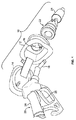
図1は、本開示の一実施形態に係る燃料注入システム10の斜視図を示している。燃料注入システム10は、例えば車両のフレームに固定することができるノズル受ハウジング12を備えてもよい。ノズル受ハウジング12は、ハウジング12に枢動可能に接続するドア14を備えてもよい。ドア14は、開放位置と閉鎖位置との間で枢動する。ハウジング12は、燃料供給装置20のノズル18を挿入することができる開口16を画定する。
FIG. 1 shows a perspective view of a
ハウジング12は、誤給油抑止装置(MFI)組立体22等の不適切な燃料ノズルの挿入抑止組立体に直接接続してもよいし、間接的に接続してもよい。MFI組立体22は、不適切な燃料供給装置(例えば、燃料注入システム10と適合しない燃料供給装置)が、MFI組立体22に接続されている給油ライン24に燃料を供給するのを防止する。例えば、MFI組立体22は、ディーゼル燃料供給装置がガソリン燃料注入システムに挿入されること又はその反対を防止する。すなわち、ディーゼル燃料供給装置は、ガソリン燃料注入システムに対して不適切であるか又は適合しない燃料供給装置であるのに対し、ガソリン燃料供給装置は、ディーゼル燃料注入システムに対して不適切であるか又は適合しない燃料供給装置である。以下で説明するように、MFI組立体22は、給油ライン24の拡張固定室内に確実に保持されるように構成してもよい。
The housing 12 may be connected directly or indirectly to an improper fuel nozzle insertion deterrent assembly such as a misfueling deterrent device (MFI)
燃料供給装置20は、トリガー28に作動的に接続されているハンドル26を備える。ハンドル28は、作業者によって把持されるように構成され、またノズル18に接続される。
The
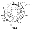
図2は、本開示の一実施形態に係る作動部材30の正面斜視図を示している。MFI組立体22(図1に示す)等のMFI組立体は、例えば、可撓性リング、締め具等の作動部材30を備えてもよい。作動部材30は、MFI本体又はMFI基部構造体の一例に相当することができる。作動部材30は、外周壁34と、ノズル通路38を囲むノズル受内面36とを有してもよい。ノズル受内面36は、例えばスリット等の間隙42によって隔てられる複数のガイド凸部40(例えば、楔形としてもよい)を有してもよい。対向するフラップ固定カラム44が、外周壁34の頂面から上方に延びてもよい。対向するフラップ固定カラム44は、協働して、例えば、ノズル通路38の出口端部を遮蔽するフラップの延長ビームを、確実にかつ枢動可能に保持する。Cリング等のばね付勢されたリングを外周壁34上又は外周壁34内に配置してもよい。
FIG. 2 shows a front perspective view of the actuating
動作の際、適切な燃料ノズルがノズル通路38に向かって動くと、燃料ノズルの遠位先端部がガイド凸部40に当接し、それによりガイド凸部40を外方に押し拡げ、そのため燃料ノズルがノズル通路38内に入ることができる。引き続き適切な燃料ノズルをノズル通路38に押し込むと、遠位先端部がフラップの前面に当接し、それにより、フラップが延長ビームとフラップ固定カラム44との接触面の回りで枢動して開放位置になる。
In operation, as the appropriate fuel nozzle moves toward the
反対に、不適切な燃料ノズルは、ガイド凸部40を押して開放位置にすることができないようなサイズ及び形状である。例えば、不適切な燃料ノズルは、ガイド凸部40間を通るには大きすぎる場合がある。別の例として、不適切な燃料ノズルがガイド凸部40間を通るように十分小さい場合、不適切な燃料ノズルのサイズは、ガイド凸部40を開放位置に拡開するのに十分な力を伴ってガイド凸部40に接触することができない場合がある。例えば、ガイド凸部40のうちの1つ又は複数を、フラップに接続するラッチ部材に作動的に結合してもよい。ガイド凸部40が開放すると、ラッチはフラップから係脱することができ、それにより、フラップが開放することを可能にする。しかし、ガイド凸部40が拡開しない場合、ラッチはフラップに固定されたままであり、それにより、フラップが開放するのが防止される。このようにして、作動部材30は、不適切な燃料ノズルが給油ラインに入るのを防止するように構成することができる。
On the other hand, an inappropriate fuel nozzle is sized and shaped so that the
作動部材30を備えるものとしてMFI組立体を記載したが、種々の他のMFI組立体を用いてもよい。例えば、MFI組立体は、拡開可能作動部材30ではなく枢動フラップを備えてもよい。枢動フラップは、不適切な燃料ノズルの遠位先端部に対して、締め付けるか、係止するか、ラッチするか、又は別様に固定し、それにより不適切な燃料ノズルがフラップを枢動して開放するのを防止する。図2に示す作動部材30は、MFI組立体とともに用いることができる構成部材の一例にすぎないことが理解される。
Although the MFI assembly has been described as including an actuating
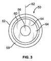
図3は、本開示の一実施形態に係る固定部材50の正面斜視図を示している。固定部材50は、MFI組立体の一部を形成してもよい。例えば、固定部材50は、図1に示す作動部材30等のMFI本体と協働して、MFI組立体を給油ラインの拡張固定室内に固定してもよい。
FIG. 3 shows a front perspective view of the fixing
固定部材50は、ノズル通路56を囲む平板状基部54を有する環状体52を含んでもよい。可撓性の弧状周壁等の弾性サスペンダー58が基部54から上方に延びてもよい。弾性サスペンダー58は、遠位縁部60におけるよりも基部54の近くでより大きい直径を有してもよい。従って、弾性サスペンダー58は、基部54から遠位縁部60にかけて、固定部材50の軸心62に向かって内方に湾曲してもよい。遠位縁部60によって開口64が画定される。開口64は、通常、ノズル通路56よりも大きい直径を有することができる。
The fixing
固定部材50は、熱可塑性エラストマー(TPE)、ゴム等のエラストマー材料等の弾性の材料で形成してもよい。以下で説明するように、固定部材50は、MFI組立体を給油ラインの固定室内に確実に保持するために、図2に示す作動部材30の端部等のMFI組立体の端部又はMFI組立体の一部に当接する。
The fixing
代替的には、種々の他のタイプの弾性固定部材を用いてもよい。例えば、弾性サスペンダー58は、連続する弾性周壁ではなく、例えば、ばねアーム、タブ、ポスト、凸部等の、基部54から延びることができる1つ又は複数の弾性ビームを有してもよい。例として、2つ、3つ、4つ以上の規則的に離間した弾性ばねアームが基部54から延びてもよい。
Alternatively, various other types of elastic fixation members may be used. For example, the
固定部材50は、例えば、図2に示す作動部材30とともにMFI組立体の一部を形成してもよい。MFI組立体は、以下で説明するように、作動部材30等のMFI本体と、1つ又は複数の固定部材50とを備えてもよい。
For example, the fixing
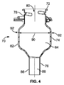
図4は、本開示の一実施形態に係る給油ライン70の軸方向断面図を示している。給油ライン70は、拡張固定室74に接続するノズル入口72を有してもよい。拡張固定室74は、燃料供給管76に更に接続する。ノズル入口72は、ノズル通路80を画定する外周壁78を有する。固定室74は、外壁78に一体に接続する外壁82を有する。固定室74の外壁82は、MFIが固定されるように構成されている内部空間84を画定する。燃料供給管76は、外壁82に一体に接続する外壁86を有する。燃料供給管76の外壁86は、燃料供給路88を画定する。
FIG. 4 shows an axial cross-sectional view of an
給油ライン70は、例えば、金属、プラスチック等の材料の一体部片として成形及び形成してもよい。代替的には、ノズル入口72、固定室74、及び/又は燃料供給管76は、溶接等によってともに固定してもよい分離した別個の部片としてもよい。
The
固定室74は、MFI組立体を収容する、給油ライン70の拡張、又は別様に拡大した容積部を提供する。MFI組立体は、拡張固定室74内に確実に保持されるように構成されている。図示のように、固定室74は、ノズル入口72及び燃料供給管76の内径及び外径を超えることができる内径90及び外径92をそれぞれ有する。例えば、固定室74の内径90は、MFI組立体の外径よりも大きく、固定部材50(図3に示す)を固定室74内で静止位置又は拡張位置に確実に懸架することを可能にするサイズであるように構成してもよい。対照的に、ノズル入口72の内径は、例えば、MFI組立体がノズル入口72に入ることを可能にしてもよいが、固定部材50がノズル入口72を通過して静止位置又は拡張位置になることを可能にするには狭すぎるようにしてもよい。燃料供給管76の内径は、MFI組立体又は固定部材50が燃料供給管76に入ることを可能にするには小さすぎるようにしてもよい。
The fixed
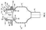
図5は、本開示の一実施形態に係る誤給油抑止装置(MFI)機構100が給油ライン70のノズル入口72に挿入されているところの軸方向断面図を示している。MFI組立体100は、作動部材30(図1に示す)等のMFI本体102と、MFI本体102の出口端部106に枢動可能に取り付けられる枢動フラップ104とを備えてもよい。代替的には、種々の他のタイプのMFI組立体を用いてもよい。
FIG. 5 shows an axial cross-sectional view of the misfueling suppression device (MFI)
前方固定部材108を、MFI本体102の出口端部106の外面に軸方向に装着してもよい。後方固定部材110を、MFI本体102の入口端部112の外面に軸方向に装着してもよい。従って、MFI本体102は、MFI組立体100の長手中心軸114に関して軸方向に前方固定部材108と後方固定部材110との間に位置決めしてもよい。MFI組立体100は、前方固定部材108及び後方固定部材110を備えてもよい。
The
図示のように、前方固定部材108及び後方固定部材110はそれぞれ反対の方向に向いてもよい。例えば、前方固定部材108の弾性サスペンダー58は下向きでもよい(図5に示す)のに対し、後方固定部材110の弾性サスペンダー58は上向きでもよい(図5に示す)。
As illustrated, the
前方固定部材108及び後方固定部材110は、MFI本体102の外面に確実に固定も接続もされずに、単にMFI本体102の外面に当接するのでもよい。代替的には、前方固定部材108及び後方固定部材110の基部116を、例えば接着剤、接合等によってMFI本体102の外面に確実に固定してもよい。
The
MFI組立体100を給油ライン70内に固定するために、MFI組立体100をノズル入口72のノズル通路80に押し込む。MFI組立体100は、ノズル通路80を通過することが可能である。しかし、弾性サスペンダー58の静止位置は、弾性サスペンダー58間にノズル入口72の内径よりも大きい場合がある距離を規定するので、ノズル入口72の内面は、弾性サスペンダー58を(例えば長手中心軸114の方へ)内方に押して圧潰する。MFI組立体100を固定室74内に固定するために、MFI組立体100を、引き続き固定室74に向かって矢印120の方向に押す。
In order to secure the
図6は、本開示の一実施形態に係るMFI組立体100が給油ライン70の固定室74内に確実に保持されているところの軸方向断面図を示している。前方固定部材108が固定室74に入る際、弾性サスペンダー58は撓み、またノズル入口72の内径132よりも大きい距離130を規定する静止位置又は別様に拡張した位置に拡張して戻る。同様に、後方固定部材110が固定室74に入る際、弾性サスペンダー58は撓み、ノズル入口72の内径よりも大きい距離130を規定する静止位置又は別様に拡張した位置に拡張して戻る。
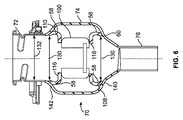
FIG. 6 shows an axial cross-sectional view where the
MFI組立体100は完全に固定室74内にあるとき、前方固定部材108の弾性サスペンダー58の遠位縁部60は、固定室74の下側内面すなわち棚部140に押し込まれるか、留められるか、固定されるか、又は別様に取り付けられるのに対し、後方固定部材110の弾性サスペンダー58の遠位縁部60は、固定室74の上側内面又は天井部142に押し込まれるか、留められるか、又は別様に取り付けられる。前方固定部材108の距離130は、前方固定部材108が燃料供給管76に入るのを可能にするには大きすぎるのに対し、後方固定部材110の距離130は、後方固定部材110が後退してノズル入口72に戻ることを可能にするには大きすぎる。従って、前方固定部材108及び後方固定部材110はそれぞれ、MFI組立体100を給油ライン70の固定室74内に確実に固定する。
When the
そのため、MFI組立体100は、分離した別個のカバーを用いずに、給油ライン70内の適所に確実に固定することができる。さらに、MFI組立体100が給油ライン70内に固定されるので、Oリング等の分離した別個のシール装置が必要でなくなる。従って、MFI組立体100は、素早く効率的に給油ラインに固定することができる。MFI組立体100は、単に給油ライン70に挿入して、固定部材108、110によって給油ライン70内に固定することができる。これは、給油ラインに別個のOリングを挿入するとともに分離した別個のカバーを圧着する、労働集約的かつ時間集約的なプロセスとは対照的である。
Therefore, the
図1〜図6を参照すると、既知のMFI組立体とは異なり、本開示の実施形態は、Oリング等の分離した別個のシールを必要とすることなく給油ラインに固定することができるMFI組立体を提供する。さらに、本開示の実施形態は、分離した別個のカバーを必要としないことができる。さらに、本開示の実施形態は、給油ラインを完全に形成した後に、MFI組立体を給油ライン内に設置することが可能である。 With reference to FIGS. 1-6, unlike known MFI assemblies, embodiments of the present disclosure are MFI assemblies that can be secured to a refueling line without the need for a separate and separate seal, such as an O-ring. Provide a solid. Further, embodiments of the present disclosure may not require a separate and separate cover. Further, embodiments of the present disclosure can install the MFI assembly in the refueling line after the refueling line is completely formed.
図5及び図6に示すように、前方固定部材108及び後方固定部材110を用いて、MFI組立体100を給油ライン70の固定室74内に固定する。代替的には、より多いか又はより少ない固定部材を用いてもよい。例えば、少なくとも一部がMFI組立体100の外周体の回りに取り付けられている単一の固定部材を用いてもよい。
As shown in FIGS. 5 and 6, the
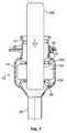
図7は、本開示の一実施形態に係る適切な燃料ノズル150がMFI組立体100に挿通されているところの軸方向断面図を示している。図示のように、適切な燃料ノズル150は、固定部材108、110の中央ノズル通路56と、MFI組立体100のノズル通路152とを通過する。従って、適切な燃料ノズル150は、給油ライン70の燃料供給管76に燃料を供給することが可能である。
FIG. 7 shows an axial cross-sectional view of a
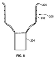
図8は、本開示の一実施形態に係る給油ライン200の軸方向断面図を示している。給油ライン200は、燃料供給管204に接続する固定室202を有する。固定室202は、MFI組立体を受けるように構成されている拡張開口部206を有する。
FIG. 8 shows an axial sectional view of an
図9は、本開示の一実施形態に係るMFI組立体210が給油ライン200の固定室202内に確実に保持されているところの軸方向断面図を示している。図示のように、MFI組立体210のMFI本体211は、軸方向に前方固定部材212と後方固定部材214との間に装着される。固定部材212、214は、固定部材212、214が弾性サスペンダー58を有しなくてもよいことを除き、上述した固定部材と同様としてもよい。その代わりに、固定部材212、214のそれぞれを、例えば中央ノズル通路を有する平板状ディスクとしてもよい。
FIG. 9 shows an axial cross-sectional view where the
固定室202の開口部206は、固定部材212、214並びにMFI本体211を受け入れるのに十分幅広い。前方固定部材212は、燃料供給管204に近接して固定室202の棚部すなわち内面216に着座する。前方固定部材212は、燃料供給管204に入るには幅広すぎる。従って、前方固定部材212は、MFI組立体210を固定室202内で懸架位置に支持する基部を提供する。後方固定部材214は、固定室内でMFI組立体210上方に位置決めされる。代替的には、前方固定部材212及び後方固定部材214のうちの一方又は双方は、弾性サスペンダーを有してもよい。弾性サスペンダーは、固定室202の内面に径方向外向きの力を印加する。
The
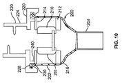
図10は、本開示の一実施形態に係る給油ライン200の固定室202内に確実に保持されているMFI組立体210上方にカバー220が取り付けられているところの軸方向断面図を示している。カバー220は、基部226に接続する入口カラム224を含んでもよい。Oリング等のシール部材228を開口部206の内面と基部226との間に位置決めしてもよい。基部226を開口部206の外面230上にスナップ係合して固定してもよい。
FIG. 10 shows an axial cross-sectional view of the
例えば、リング、ポスト、スタッド等の圧迫部材240が、基部226から下方に延び、後方固定部材214の頂面に当接してもよい。基部226が給油ライン200の開口部206にスナップ係合して固定されると、圧迫部材240は、後方固定部材214に向かって圧迫力を印加し、この圧迫力が後方固定部材214を適所に固定する。従って、後方固定部材214が開口部206から後退することが防止される。同時に、後方固定部材214は、MFI本体211が後方固定部材214と固定室202の棚部216に留められている前方固定部材212との間に懸架されることにより、後方固定部材214は固定室202の更に内方に入るのが阻止される。従って、MFI組立体210を給油ライン200の固定室202内に確実に固定することができる。
For example, a
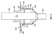
図11は、本開示の一実施形態に係る適切な燃料ノズル260が給油ライン200の固定室202内にあるMFI組立体210に挿通されているところの軸方向断面図を示している。カバー220の基部226の上面又は外面262を、車両の外側フレーム等のパネル266の下面又は内面264に取り付けてもよい。
FIG. 11 shows an axial cross-sectional view of a
適切な燃料ノズル260は、MFI組立体210並びに固定部材212、214のノズル通路を通過することが可能である。従って、適切な燃料ノズル260は、給油ライン200の燃料供給管204に燃料を供給することができる。
A
図8〜図11を参照すると、本開示の実施形態は、カバー及びシール部材を用いてもよい、MFI組立体を給油ラインに固定するシステム及び方法を提供することができる。代替的には、カバー220を、例えば、TPE、ゴム等のエラストマー材料でオーバーモールドし、それにより別個のOリング又はガスケットの必要性を排除してもよい。
With reference to FIGS. 8-11, embodiments of the present disclosure can provide a system and method for securing an MFI assembly to a refueling line that may employ a cover and a seal member. Alternatively, the
図1〜図11を参照すると、本開示の実施形態は、MFI組立体を給油ライン内に効率的に固定するシステム及び方法を提供する。給油ラインは、拡張固定室を有してもよい。この拡張固定室は、MFI組立体及び1つ又は複数の固定部材を該固定室内で位置決め及び固定することを可能にする。 With reference to FIGS. 1-11, embodiments of the present disclosure provide a system and method for efficiently securing an MFI assembly within a refueling line. The oil supply line may have an extended fixed chamber. This extended fixation chamber allows the MFI assembly and one or more fixation members to be positioned and fixed within the fixation chamber.
本開示の実施形態は、商用トラック等の比較的大型の車両とともに用いるように構成してもよい。給油ラインの拡張固定室は、より大きくより堅牢なMFI組立体を収容することができるものとしてもよい。 Embodiments of the present disclosure may be configured for use with relatively large vehicles such as commercial trucks. The expansion fixed chamber of the refueling line may be capable of accommodating a larger and more robust MFI assembly.
本開示の実施形態を説明するために上部、底部、下側、中間、横、水平、垂直、前方等の種々の空間及び方向に関する用語を用いる場合があるが、そのような用語は図面に示される向きに関して用いられるにすぎないことが理解される。それらの向きは、上側部分が下側部分であり、逆もまた同様であり、水平が垂直になるといったように、反転させるか、回転させるか、又は別様に変更することができる。 Various space and orientation terms such as top, bottom, bottom, middle, side, horizontal, vertical, front, etc. may be used to describe embodiments of the present disclosure, such terms are shown in the drawings. It is understood that it is only used with respect to the orientation that is being used. Their orientation can be reversed, rotated, or otherwise changed such that the upper part is the lower part and vice versa, and the horizontal is vertical.
上記の変形及び変更は本開示の範囲内にある。本明細書に開示及び規定されている本実施形態は、言及されているか、又は本文及び/又は図面から明らかである個々の特徴の2つ以上の全ての代替的な組合せに及ぶことが理解される。これらの様々な組合せの全ては、本開示の種々の代替的な態様を構成する。本明細書に記載の実施形態は、本開示を実施するための分かっている最良の形態を説明しており、当業者が本開示を利用することを可能にする。特許請求の範囲は、従来技術が許容する範囲まで代替的な実施形態を含むものと解釈すべきである。 Such variations and modifications are within the scope of this disclosure. It is understood that the embodiments disclosed and defined herein extend to all alternative combinations of two or more of the individual features mentioned or apparent from the text and / or drawings. The All of these various combinations constitute various alternative aspects of the disclosure. The embodiments described herein illustrate the best mode known for carrying out the disclosure and enable those skilled in the art to utilize the disclosure. The claims should be construed to include alternative embodiments to the extent permitted by the prior art.
添付の特許請求の範囲で用いられる範囲では、「including」及び「in which」という用語は、それぞれ「comprising」及び「wherein」という用語のプレインイングリッシュでの同義語として用いられている。さらに、添付の特許請求の範囲で用いられる範囲では、「第1の」、「第2の」、及び「第3の」等の用語は、単に標識として用いられており、これらの用語の対象物に対し、数に関する要件を課すことは意図していない。さらに、添付の特許請求の範囲の限定は、ミーンズプラスファンクション形式で記載されていない。このような特許請求の範囲の限定は、更なる構造を記述しない機能的表現に伴い「手段(means for)」という句を明示的に用いていない限り、かつ明示的に用いるまで、米国特許法第112条(f)項に基づき解釈されることは意図していない。 In the scope used in the appended claims, the terms “including” and “in which” are used as synonyms in plain English for the terms “comprising” and “wherein”, respectively. Further, in the scope used in the appended claims, terms such as “first”, “second”, and “third” are merely used as labels, and the terms of these terms It is not intended to impose numerical requirements on things. Furthermore, the limitations of the appended claims are not described in a means plus function format. Such limitation of the claims is subject to U.S. patent law unless and until it is explicitly used with the phrase "means for" with a functional expression that does not describe further structure. It is not intended to be interpreted under section 112 (f).
本開示の種々の特徴は添付の特許請求の範囲内に記載されている。 Various features of the disclosure are set forth in the appended claims.
10 燃料注入システム
12 ノズル受ハウジング
14 ドア
16 開口
18 ノズル
20 燃料供給装置
22 誤給油抑止装置(MFI)組立体
24 給油ライン
26 ハンドル
28 トリガー
30 拡開可能作動部材
34 外周壁
36 ノズル受内面
38 ノズル通路
40 ガイド凸部
42 間隙
44 フラップ固定カラム
50 固定部材
52 環状体
54 平板状基部
56 中央ノズル通路
58 弾性サスペンダー
60 遠位縁部
62 軸心
64 開口
70 給油ライン
72 ノズル入口
74 拡張固定室
76 燃料供給管
78 外周壁
80 ノズル通路
82 外壁
84 内部空間
86 外壁
88 燃料供給路
90 内径
92 外径
100 誤給油抑止装置(MFI)機構
102 本体
104 枢動フラップ
106 出口端部
108 前方固定部材
110 後方固定部材
112 入口端部
114 長手中心軸
116 基部
120 矢印
130 距離
132 内径
140 棚部
142 天井部
150 燃料ノズル
152 ノズル通路
200 給油ライン
202 固定室
204 燃料供給管
206 拡張開口部
210 組立体
211 本体
212 前方固定部材
214 後方固定部材
220 カバー
224 入口カラム
226 基部
228 シール部材
230 外面
240 圧迫部材
260 燃料ノズル
262 外面
264 内面
266 パネル
DESCRIPTION OF
Claims (20)
MFIノズル通路を内部に形成した本体であって、該本体は、適切な燃料ノズルが前記MFIノズル通路を通過することを可能にするように構成され、該本体は、前記不適切な燃料ノズルが前記MFIノズル通路を通過することを防止する本体と、
給油ライン内にある前記本体に接続するように構成され、該本体を該給油ライン内に確実に保持する少なくとも1つの固定部材とを備える誤給油抑止装置組立体。 A misfueling deterrent (MFI) assembly in which an inappropriate fuel nozzle prevents fuel supply to the fuel tank,
A body having an MFI nozzle passage formed therein, the body configured to allow a suitable fuel nozzle to pass through the MFI nozzle passage, the body including the inappropriate fuel nozzle; A body for preventing passage through the MFI nozzle passage;
An erroneous oil suppression device assembly comprising: at least one fixing member configured to connect to the main body in the oil supply line and securely holding the main body in the oil supply line.
前記給油ライン内にある前記本体の第1の端部に接続する第1の固定部材と、
前記給油ライン内にある前記本体の前記第1の端部の反対側にある前記第2の端部に接続する第2の固定部材とを含む請求項1に記載のMFI組立体。 The at least one fixing member is
A first fixing member connected to a first end of the main body in the oiling line;
The MFI assembly according to claim 1, further comprising: a second fixing member connected to the second end of the main body in the oil supply line opposite to the first end of the main body.
前記燃料タンクに接続する燃料供給管に接続する固定室を有する給油ラインであって、該固定室は第1の内径を有し、前記燃料供給管は、該第1の内径よりも小さい第2の内径を有する給油ラインと、
前記固定室内に固定される誤給油抑止装置(MFI)組立体とを備え、
前記MFI組立体は、
MFIノズル通路を内部に形成した本体であって、該本体は、適切な燃料ノズルが前記MFIノズル通路を通過することを可能にするように構成され、該本体は、前記不適切な燃料ノズルが前記MFIノズル通路を通過することを防止する本体と、
前記給油ライン内にある前記本体の第1の端部に接続し、前記燃料供給管に近接するが該燃料供給管に入ることはできない前方固定部材と、
前記給油ライン内にある前記本体の前記第1の端部の反対側にある第2の端部に接続する後方固定部材とを備え、
前記前方固定部材及び前記後方固定部材は、協働して前記本体を前記固定室内に固定する不適切な燃料ノズルの挿入抑止システム。 An improper fuel nozzle insertion deterrent system in which an improper fuel nozzle prevents fuel supply to the fuel tank,
A fuel supply line having a fixed chamber connected to a fuel supply pipe connected to the fuel tank, wherein the fixed chamber has a first inner diameter, and the fuel supply pipe is a second smaller than the first inner diameter. An oiling line having an inner diameter of
A misfueling suppression device (MFI) assembly fixed in the fixed chamber;
The MFI assembly is:
A body having an MFI nozzle passage formed therein, the body configured to allow a suitable fuel nozzle to pass through the MFI nozzle passage, the body including the inappropriate fuel nozzle; A body for preventing passage through the MFI nozzle passage;
A front fixing member connected to the first end of the main body in the refueling line, close to the fuel supply pipe but not allowed to enter the fuel supply pipe;
A rear securing member connected to a second end on the opposite side of the first end of the body in the oiling line;
The front fixing member and the rear fixing member cooperate to fix the main body in the fixing chamber, and an inappropriate fuel nozzle insertion suppression system.
該MFI組立体は、
MFIノズル通路を内部に形成した本体であって、該本体は、適切な燃料ノズルが前記MFIノズル通路を通過することを可能にするように構成され、該本体は、前記不適切な燃料ノズルが前記MFIノズル通路を通過することを防止するように構成され、該本体は、作動リングと、該作動リングに枢動可能に取り付けられるフラップとを含む本体と、
前記給油ライン内にある前記本体の第1の端部に接続し、燃料供給管に近接するが該燃料供給管に入ることはできないサイズである前方固定部材と、
前記給油ライン内にある前記本体の前記第1の端部の反対側にある第2の端部に接続する後方固定部材とを備え、
前記前方固定部材及び前記後方固定部材は、協働して前記本体を前記給油ラインの前記固定室内に固定するように構成され、
前記前方固定部材及び前記後方固定部材の各々が、前記固定室内に固定されるように構成されている平板状基部を有し、該平板状基部を通ってノズル固定通路が形成される誤給油抑止装置組立体。 Misfueling deterring device (MFI) assembly in which an improper fuel nozzle prevents fuel supply to the fuel tank, the MFI assembly being fixed in a fuel line having an extended fixed chamber connected to a fuel supply pipe Configured to be
The MFI assembly is
A body having an MFI nozzle passage formed therein, the body configured to allow a suitable fuel nozzle to pass through the MFI nozzle passage, the body including the inappropriate fuel nozzle; A body configured to prevent passage through the MFI nozzle passage, the body including an actuation ring and a flap pivotally attached to the actuation ring;
A front fixing member connected to a first end of the main body in the refueling line and having a size close to the fuel supply pipe but not allowed to enter the fuel supply pipe;
A rear securing member connected to a second end on the opposite side of the first end of the body in the oiling line;
The front fixing member and the rear fixing member are configured to cooperate to fix the main body in the fixing chamber of the oil supply line,
Each of the front fixing member and the rear fixing member has a flat base portion configured to be fixed in the fixing chamber, and a mis-lubrication suppression is performed in which a nozzle fixing passage is formed through the flat base portion. Device assembly.
Applications Claiming Priority (3)
| Application Number | Priority Date | Filing Date | Title |
|---|---|---|---|
| US201361812515P | 2013-04-16 | 2013-04-16 | |
| US61/812,515 | 2013-04-16 | ||
| PCT/US2014/032068 WO2014172087A1 (en) | 2013-04-16 | 2014-03-27 | Improper fuel nozzle insertion-inhibiting system |
Publications (3)
| Publication Number | Publication Date |
|---|---|
| JP2016516632A true JP2016516632A (en) | 2016-06-09 |
| JP2016516632A5 JP2016516632A5 (en) | 2017-05-18 |
| JP6466915B2 JP6466915B2 (en) | 2019-02-06 |
Family
ID=50549496
Family Applications (1)
| Application Number | Title | Priority Date | Filing Date |
|---|---|---|---|
| JP2016508948A Active JP6466915B2 (en) | 2013-04-16 | 2014-03-27 | Improper fuel nozzle insertion suppression system |
Country Status (5)
| Country | Link |
|---|---|
| US (1) | US9522594B2 (en) |
| JP (1) | JP6466915B2 (en) |
| CN (1) | CN105121206B (en) |
| DE (1) | DE112014000715T5 (en) |
| WO (1) | WO2014172087A1 (en) |
Families Citing this family (4)
| Publication number | Priority date | Publication date | Assignee | Title |
|---|---|---|---|---|
| US9481240B1 (en) * | 2015-04-27 | 2016-11-01 | GM Global Technology Operations LLC | Cover assembly for a filling port of a vehicle |
| US10800648B2 (en) * | 2017-03-01 | 2020-10-13 | Ford Global Technologies, Llc | Funnel for a fuel tank filler pipe |
| US10569645B2 (en) * | 2017-03-01 | 2020-02-25 | Ford Global Technologies, Llc | Insert for a fuel tank filler pipe |
| JP6911736B2 (en) * | 2017-12-04 | 2021-07-28 | トヨタ自動車株式会社 | Vehicle refueling section structure |
Citations (4)
| Publication number | Priority date | Publication date | Assignee | Title |
|---|---|---|---|---|
| JP2006103679A (en) * | 2004-09-30 | 2006-04-20 | Stant Manufacturing Inc | Fuel-dispensing nozzle inhibitor |
| WO2009013558A1 (en) * | 2007-07-23 | 2009-01-29 | Renault Trucks | Arrangement of a filler neck for a vehicle tank |
| JP2012116380A (en) * | 2010-12-02 | 2012-06-21 | Nifco Inc | Guide device for fuel filler nozzle |
| WO2012108119A1 (en) * | 2011-02-07 | 2012-08-16 | 株式会社ニフコ | Fuel-filler aperture opening/closing device |
Family Cites Families (13)
| Publication number | Priority date | Publication date | Assignee | Title |
|---|---|---|---|---|
| FR2753138B1 (en) | 1996-09-12 | 1998-10-16 | Journee Paul Sa | DEVICE FOR FILLING A MOTOR VEHICLE FUEL TANK HAVING GAS PRESSURE TARGETING MEANS |
| RU2221975C2 (en) | 1999-02-05 | 2004-01-20 | Маннесманнрёрен-Верке Аг | Blast tuyere for shaft furnaces, specifically, for blast furnaces or hot-blast cupola |
| US7549443B2 (en) | 2003-12-09 | 2009-06-23 | Illinois Tool Works Inc. | Fuel shut-off valve assembly with associated components and methods of making and assembling the same |
| DE102004002994B3 (en) | 2004-01-19 | 2005-09-22 | Itw Automotive Products Gmbh & Co. Kg | Filler neck for filling fuel into a vehicle tank |
| US7182111B2 (en) * | 2004-08-11 | 2007-02-27 | Stant Manufacturing Inc. | Fuel-dispensing nozzle inhibitor |
| JP4769600B2 (en) * | 2006-03-09 | 2011-09-07 | 本田技研工業株式会社 | Filling port device |
| US20080295906A1 (en) * | 2007-05-29 | 2008-12-04 | Mccracken Douglas D | Fuel filler neck assembly and method of fabricating |
| GB2450763A (en) * | 2007-07-03 | 2009-01-07 | Edwin Michael Stephenson | A fuel dispensing nozzle inhibitor assembly |
| DE102008040715B4 (en) * | 2008-07-25 | 2013-04-25 | Alfmeier Präzision AG Baugruppen und Systemlösungen | Filler neck for a motor vehicle tank |
| DE112009001823T5 (en) | 2008-08-20 | 2011-06-01 | Illinois Tool Works Inc., Glenview | Mis-fuel inhibitor |
| EP2406095B1 (en) * | 2009-03-12 | 2013-11-06 | Illinois Tool Works Inc. | Mis-fuel inhibitor |
| WO2011053563A1 (en) | 2009-10-30 | 2011-05-05 | Illinois Tool Works Inc. | Capless refueling system |
| CN102656043A (en) * | 2009-12-17 | 2012-09-05 | 本田技研工业株式会社 | Vehicle fuel supply pipe device |
-
2014
- 2014-03-27 DE DE112014000715.3T patent/DE112014000715T5/en active Pending
- 2014-03-27 JP JP2016508948A patent/JP6466915B2/en active Active
- 2014-03-27 US US14/782,349 patent/US9522594B2/en active Active
- 2014-03-27 WO PCT/US2014/032068 patent/WO2014172087A1/en not_active Ceased
- 2014-03-27 CN CN201480022035.3A patent/CN105121206B/en not_active Expired - Fee Related
Patent Citations (4)
| Publication number | Priority date | Publication date | Assignee | Title |
|---|---|---|---|---|
| JP2006103679A (en) * | 2004-09-30 | 2006-04-20 | Stant Manufacturing Inc | Fuel-dispensing nozzle inhibitor |
| WO2009013558A1 (en) * | 2007-07-23 | 2009-01-29 | Renault Trucks | Arrangement of a filler neck for a vehicle tank |
| JP2012116380A (en) * | 2010-12-02 | 2012-06-21 | Nifco Inc | Guide device for fuel filler nozzle |
| WO2012108119A1 (en) * | 2011-02-07 | 2012-08-16 | 株式会社ニフコ | Fuel-filler aperture opening/closing device |
Also Published As
| Publication number | Publication date |
|---|---|
| US20160039280A1 (en) | 2016-02-11 |
| WO2014172087A1 (en) | 2014-10-23 |
| CN105121206B (en) | 2018-04-13 |
| JP6466915B2 (en) | 2019-02-06 |
| DE112014000715T5 (en) | 2015-10-29 |
| US9522594B2 (en) | 2016-12-20 |
| CN105121206A (en) | 2015-12-02 |
Similar Documents
| Publication | Publication Date | Title |
|---|---|---|
| JP6466915B2 (en) | Improper fuel nozzle insertion suppression system | |
| JP5596712B2 (en) | Lubrication prevention device | |
| JP4849345B2 (en) | Refueling closure assembly and method of manufacturing the same | |
| US4501374A (en) | Hazardous fluid tank with check valve | |
| US10625601B2 (en) | Improper fuel nozzle insertion-inhibiting assembly | |
| US9102230B2 (en) | Fuel tank opening and closing device | |
| US9744849B2 (en) | Fuel nozzle receiving assembly | |
| US20180186305A1 (en) | Service hole fastening clip assembly | |
| CN104943557A (en) | Charging housing or filler neck housing | |
| JP2005350061A (en) | Fuel tank filler tube assembly and method for forming fuel tank filler tube | |
| KR20120100955A (en) | Capless refueling system | |
| JP2009202863A (en) | Hood flip-up device | |
| US20170297426A1 (en) | System and method for grounding a fuel intake system | |
| US20090095373A1 (en) | Fuel intake assembly for filling a vehicle tank with diesel fuel | |
| JP2010006246A (en) | Fuel supply device | |
| CN106029423A (en) | Improper fuel nozzle insertion-inhibiting assembly | |
| JP2004136835A (en) | Valve unit mounting structure | |
| JP2001163069A (en) | Oil feeder for fuel tank, and fuel tank | |
| CN106641532B (en) | Quick connector for fuel delivery lines | |
| JP2015202774A (en) | Washing device for vehicle | |
| US9662972B2 (en) | Draining fuel nozzle-receiving assembly | |
| JP2000280764A (en) | Oil supplying device of fuel tank | |
| JP7214584B2 (en) | Connection structure of the filter case | |
| JP6486183B2 (en) | Refueling system and assembly method thereof | |
| JP2011102055A (en) | Cleaning device of vehicle lighting fixture |
Legal Events
| Date | Code | Title | Description |
|---|---|---|---|
| A521 | Request for written amendment filed |
Free format text: JAPANESE INTERMEDIATE CODE: A523 Effective date: 20170327 |
|
| A621 | Written request for application examination |
Free format text: JAPANESE INTERMEDIATE CODE: A621 Effective date: 20170327 |
|
| A977 | Report on retrieval |
Free format text: JAPANESE INTERMEDIATE CODE: A971007 Effective date: 20180125 |
|
| A131 | Notification of reasons for refusal |
Free format text: JAPANESE INTERMEDIATE CODE: A131 Effective date: 20180130 |
|
| A601 | Written request for extension of time |
Free format text: JAPANESE INTERMEDIATE CODE: A601 Effective date: 20180427 |
|
| A521 | Request for written amendment filed |
Free format text: JAPANESE INTERMEDIATE CODE: A523 Effective date: 20180726 |
|
| TRDD | Decision of grant or rejection written | ||
| A01 | Written decision to grant a patent or to grant a registration (utility model) |
Free format text: JAPANESE INTERMEDIATE CODE: A01 Effective date: 20181211 |
|
| A61 | First payment of annual fees (during grant procedure) |
Free format text: JAPANESE INTERMEDIATE CODE: A61 Effective date: 20190110 |
|
| R150 | Certificate of patent or registration of utility model |
Ref document number: 6466915 Country of ref document: JP Free format text: JAPANESE INTERMEDIATE CODE: R150 |
|
| R250 | Receipt of annual fees |
Free format text: JAPANESE INTERMEDIATE CODE: R250 |
|
| R250 | Receipt of annual fees |
Free format text: JAPANESE INTERMEDIATE CODE: R250 |
|
| R250 | Receipt of annual fees |
Free format text: JAPANESE INTERMEDIATE CODE: R250 |
|
| R250 | Receipt of annual fees |
Free format text: JAPANESE INTERMEDIATE CODE: R250 |
|
| R250 | Receipt of annual fees |
Free format text: JAPANESE INTERMEDIATE CODE: R250 |