JP2016511027A - Lung denervation system and method - Google Patents
Lung denervation system and method Download PDFInfo
- Publication number
- JP2016511027A JP2016511027A JP2015557114A JP2015557114A JP2016511027A JP 2016511027 A JP2016511027 A JP 2016511027A JP 2015557114 A JP2015557114 A JP 2015557114A JP 2015557114 A JP2015557114 A JP 2015557114A JP 2016511027 A JP2016511027 A JP 2016511027A
- Authority
- JP
- Japan
- Prior art keywords
- treatment
- patient
- lung
- nerve
- image
- Prior art date
- Legal status (The legal status is an assumption and is not a legal conclusion. Google has not performed a legal analysis and makes no representation as to the accuracy of the status listed.)
- Pending
Links
Images


Classifications
-
- A—HUMAN NECESSITIES
- A61—MEDICAL OR VETERINARY SCIENCE; HYGIENE
- A61N—ELECTROTHERAPY; MAGNETOTHERAPY; RADIATION THERAPY; ULTRASOUND THERAPY
- A61N5/00—Radiation therapy
- A61N5/10—X-ray therapy; Gamma-ray therapy; Particle-irradiation therapy
- A61N5/103—Treatment planning systems
- A61N5/1039—Treatment planning systems using functional images, e.g. PET or MRI
-
- A—HUMAN NECESSITIES
- A61—MEDICAL OR VETERINARY SCIENCE; HYGIENE
- A61B—DIAGNOSIS; SURGERY; IDENTIFICATION
- A61B34/00—Computer-aided surgery; Manipulators or robots specially adapted for use in surgery
- A61B34/10—Computer-aided planning, simulation or modelling of surgical operations
-
- A—HUMAN NECESSITIES
- A61—MEDICAL OR VETERINARY SCIENCE; HYGIENE
- A61B—DIAGNOSIS; SURGERY; IDENTIFICATION
- A61B34/00—Computer-aided surgery; Manipulators or robots specially adapted for use in surgery
- A61B34/20—Surgical navigation systems; Devices for tracking or guiding surgical instruments, e.g. for frameless stereotaxis
-
- A—HUMAN NECESSITIES
- A61—MEDICAL OR VETERINARY SCIENCE; HYGIENE
- A61B—DIAGNOSIS; SURGERY; IDENTIFICATION
- A61B34/00—Computer-aided surgery; Manipulators or robots specially adapted for use in surgery
- A61B34/25—User interfaces for surgical systems
-
- A—HUMAN NECESSITIES
- A61—MEDICAL OR VETERINARY SCIENCE; HYGIENE
- A61B—DIAGNOSIS; SURGERY; IDENTIFICATION
- A61B90/00—Instruments, implements or accessories specially adapted for surgery or diagnosis and not covered by any of the groups A61B1/00 - A61B50/00, e.g. for luxation treatment or for protecting wound edges
- A61B90/36—Image-producing devices or illumination devices not otherwise provided for
- A61B90/37—Surgical systems with images on a monitor during operation
-
- A—HUMAN NECESSITIES
- A61—MEDICAL OR VETERINARY SCIENCE; HYGIENE
- A61N—ELECTROTHERAPY; MAGNETOTHERAPY; RADIATION THERAPY; ULTRASOUND THERAPY
- A61N5/00—Radiation therapy
- A61N5/10—X-ray therapy; Gamma-ray therapy; Particle-irradiation therapy
- A61N5/1048—Monitoring, verifying, controlling systems and methods
- A61N5/1049—Monitoring, verifying, controlling systems and methods for verifying the position of the patient with respect to the radiation beam
-
- A—HUMAN NECESSITIES
- A61—MEDICAL OR VETERINARY SCIENCE; HYGIENE
- A61B—DIAGNOSIS; SURGERY; IDENTIFICATION
- A61B34/00—Computer-aided surgery; Manipulators or robots specially adapted for use in surgery
- A61B34/10—Computer-aided planning, simulation or modelling of surgical operations
- A61B2034/101—Computer-aided simulation of surgical operations
- A61B2034/105—Modelling of the patient, e.g. for ligaments or bones
-
- A—HUMAN NECESSITIES
- A61—MEDICAL OR VETERINARY SCIENCE; HYGIENE
- A61B—DIAGNOSIS; SURGERY; IDENTIFICATION
- A61B34/00—Computer-aided surgery; Manipulators or robots specially adapted for use in surgery
- A61B34/10—Computer-aided planning, simulation or modelling of surgical operations
- A61B2034/107—Visualisation of planned trajectories or target regions
-
- A—HUMAN NECESSITIES
- A61—MEDICAL OR VETERINARY SCIENCE; HYGIENE
- A61B—DIAGNOSIS; SURGERY; IDENTIFICATION
- A61B34/00—Computer-aided surgery; Manipulators or robots specially adapted for use in surgery
- A61B34/20—Surgical navigation systems; Devices for tracking or guiding surgical instruments, e.g. for frameless stereotaxis
- A61B2034/2046—Tracking techniques
- A61B2034/2051—Electromagnetic tracking systems
-
- A—HUMAN NECESSITIES
- A61—MEDICAL OR VETERINARY SCIENCE; HYGIENE
- A61B—DIAGNOSIS; SURGERY; IDENTIFICATION
- A61B34/00—Computer-aided surgery; Manipulators or robots specially adapted for use in surgery
- A61B34/25—User interfaces for surgical systems
- A61B2034/256—User interfaces for surgical systems having a database of accessory information, e.g. including context sensitive help or scientific articles
-
- A—HUMAN NECESSITIES
- A61—MEDICAL OR VETERINARY SCIENCE; HYGIENE
- A61N—ELECTROTHERAPY; MAGNETOTHERAPY; RADIATION THERAPY; ULTRASOUND THERAPY
- A61N5/00—Radiation therapy
- A61N5/10—X-ray therapy; Gamma-ray therapy; Particle-irradiation therapy
- A61N5/1048—Monitoring, verifying, controlling systems and methods
- A61N5/1049—Monitoring, verifying, controlling systems and methods for verifying the position of the patient with respect to the radiation beam
- A61N2005/1051—Monitoring, verifying, controlling systems and methods for verifying the position of the patient with respect to the radiation beam using an active marker
-
- A—HUMAN NECESSITIES
- A61—MEDICAL OR VETERINARY SCIENCE; HYGIENE
- A61N—ELECTROTHERAPY; MAGNETOTHERAPY; RADIATION THERAPY; ULTRASOUND THERAPY
- A61N5/00—Radiation therapy
- A61N5/10—X-ray therapy; Gamma-ray therapy; Particle-irradiation therapy
- A61N5/1048—Monitoring, verifying, controlling systems and methods
- A61N5/1049—Monitoring, verifying, controlling systems and methods for verifying the position of the patient with respect to the radiation beam
- A61N2005/1055—Monitoring, verifying, controlling systems and methods for verifying the position of the patient with respect to the radiation beam using magnetic resonance imaging [MRI]
-
- A—HUMAN NECESSITIES
- A61—MEDICAL OR VETERINARY SCIENCE; HYGIENE
- A61N—ELECTROTHERAPY; MAGNETOTHERAPY; RADIATION THERAPY; ULTRASOUND THERAPY
- A61N5/00—Radiation therapy
- A61N5/10—X-ray therapy; Gamma-ray therapy; Particle-irradiation therapy
- A61N5/1048—Monitoring, verifying, controlling systems and methods
- A61N5/1049—Monitoring, verifying, controlling systems and methods for verifying the position of the patient with respect to the radiation beam
- A61N2005/1058—Monitoring, verifying, controlling systems and methods for verifying the position of the patient with respect to the radiation beam using ultrasound imaging
-
- A—HUMAN NECESSITIES
- A61—MEDICAL OR VETERINARY SCIENCE; HYGIENE
- A61N—ELECTROTHERAPY; MAGNETOTHERAPY; RADIATION THERAPY; ULTRASOUND THERAPY
- A61N5/00—Radiation therapy
- A61N5/10—X-ray therapy; Gamma-ray therapy; Particle-irradiation therapy
- A61N5/1048—Monitoring, verifying, controlling systems and methods
- A61N5/1064—Monitoring, verifying, controlling systems and methods for adjusting radiation treatment in response to monitoring
- A61N5/1068—Gating the beam as a function of a physiological signal
Landscapes
- Health & Medical Sciences (AREA)
- Engineering & Computer Science (AREA)
- Life Sciences & Earth Sciences (AREA)
- Biomedical Technology (AREA)
- Nuclear Medicine, Radiotherapy & Molecular Imaging (AREA)
- Surgery (AREA)
- Veterinary Medicine (AREA)
- Animal Behavior & Ethology (AREA)
- General Health & Medical Sciences (AREA)
- Public Health (AREA)
- Radiology & Medical Imaging (AREA)
- Pathology (AREA)
- Heart & Thoracic Surgery (AREA)
- Medical Informatics (AREA)
- Molecular Biology (AREA)
- Robotics (AREA)
- Gynecology & Obstetrics (AREA)
- Oral & Maxillofacial Surgery (AREA)
- Human Computer Interaction (AREA)
- Apparatus For Radiation Diagnosis (AREA)
- Magnetic Resonance Imaging Apparatus (AREA)
- Radiation-Therapy Devices (AREA)
Abstract
肺疾患の症状を示す肺の少なくとも部分の画像の第1のセットをとること、画像の第1のセットから3次元モデルを生成すること、肺の部分直近の対象の神経を位置確認すること、治療計画を生成すること、および、肺の部分の機能が影響を受けるように、治療計画に基き対象の神経を非侵襲的に除神経することを含む、肺疾患を治療するシステムおよび方法。【選択図】図1Taking a first set of images of at least a portion of the lung showing symptoms of pulmonary disease, generating a three-dimensional model from the first set of images, locating the nerve of the subject in the immediate vicinity of the lung portion, A system and method for treating a pulmonary disease comprising generating a treatment plan and noninvasively denervating a target nerve based on the treatment plan such that the function of a portion of the lung is affected. [Selection] Figure 1
Description
本出願は、2013年2月8日出願の米国仮特許出願第61/762,741号、および2014年2月7日出願の米国仮特許出願第61/936,933号の受益および優先権を主張し、それらの全体の内容は参照により本明細書に組み込まれる。 This application claims the benefit and priority of US Provisional Patent Application No. 61 / 762,741 filed on Feb. 8, 2013 and US Provisional Patent Application No. 61 / 936,933 filed on Feb. 7, 2014. And their entire contents are incorporated herein by reference.
本開示は、肺疾患を治療するシステムおよび方法に関する。とりわけ、本開示は、肺の1つまたは複数の対象の神経を識別し、肺の3次元モデルに基き対象の神経を非侵襲的に治療するシステムおよび方法に関する。 The present disclosure relates to systems and methods for treating lung disease. In particular, the present disclosure relates to a system and method for identifying one or more target nerves of the lung and non-invasively treating the target nerve based on a three-dimensional model of the lung.
喘息、慢性閉塞性肺疾患(COPD)および慢性閉塞性肺疾患(COLD)、または気腫、慢性気管支炎のような肺に関する疾患、胃食道逆流、心血管疾患および鼻副鼻腔炎の診療基準は、医療および/または薬剤管理上で広く注目されており、それらは一般に患者に侵襲性が高い。例えば、局所的および侵襲的手段(例えば、手術)による肺の除神経は、喘息または気腫に治療の利点をもたらすかもしれないと何十年も報告されてきた。 Clinical criteria for asthma, chronic obstructive pulmonary disease (COPD) and chronic obstructive pulmonary disease (COLD), or pulmonary diseases such as emphysema, chronic bronchitis, gastroesophageal reflux, cardiovascular disease and rhinosinusitis are They have gained widespread attention in medical and / or drug management and are generally highly invasive to patients. For example, it has been reported for decades that pulmonary denervation by local and invasive means (eg, surgery) may provide therapeutic benefits for asthma or emphysema.
空気流の少なさは、一般的に肺の機能停止をもたらし、それが肺疾患を引き起こす。ときどき、肺胞の壁が損傷され、結果として吸入および呼気間の空気量が減少し、肺疾患の症状が増加するように、空気が損傷された肺胞の内部に閉じ込められる。損傷された肺胞を治療する1つの方法は、損傷された肺胞の収縮に影響する神経の機能の全体または一部を停止させるための神経の除神経でありうる。対象に切除装置を挿入することにより神経を除神経する、いくつかの医療装置が開発されてきた。肺の患者の疾患および技術的困難を含むさまざまな理由で、除神経のためのそのような装置の採用は比較的弱い。本開示は、より広い範囲の患者に適用可能でありうる治療の代替的な方法論を提供する。 Low airflow generally results in lung cessation, which causes lung disease. Sometimes the air is trapped inside the damaged alveoli so that the walls of the alveoli are damaged, resulting in decreased air volume between inhalation and expiration and increased symptoms of lung disease. One method of treating the damaged alveoli may be neural denervation to stop all or part of the nerve function that affects the contraction of the damaged alveoli. Several medical devices have been developed that denervate nerves by inserting an ablation device into a subject. For a variety of reasons, including lung patient disease and technical difficulties, the adoption of such devices for denervation is relatively weak. The present disclosure provides alternative methodologies for treatment that may be applicable to a wider range of patients.
態様で、本開示は肺疾患を治療する方法を特徴とする。方法は、肺疾患の症状を示す肺の少なくとも部分の画像の第1のセットをとること、画像の第1のセットから3次元モデルを生成すること、肺の部分直近の対象の神経を位置確認すること、治療計画を生成すること、および肺の部分の機能が影響を受けるように、治療計画に基き対象の神経を非侵襲的に除神経することを含む。 In an aspect, the disclosure features a method of treating a pulmonary disease. The method takes a first set of images of at least a portion of the lung showing symptoms of pulmonary disease, generates a three-dimensional model from the first set of images, and locates the nerves of the subject closest to the portion of the lung And generating a treatment plan and denervating a target nerve non-invasively based on the treatment plan such that the function of a portion of the lung is affected.
態様で、治療計画は、治療のサイズ、治療ベクトル、神経の位置、エネルギー量または治療期間の1つまたは複数を含む。治療のサイズは、肺疾患の症状の重症度、対象の神経の位置、対象の神経のサイズ、および除神経が一時的か永続的かの1つまたは複数に基き計算される。対象の神経の非侵襲的な除神経は、治療期間中に対象の神経にエネルギー量を放射することを含む。 In an aspect, a treatment plan includes one or more of treatment size, treatment vector, nerve location, energy amount or treatment duration. The size of the treatment is calculated based on one or more of the severity of the symptoms of pulmonary disease, the location of the subject's nerves, the size of the subject's nerves, and whether denervation is temporary or permanent. Non-invasive denervation of the subject's nerve involves radiating an amount of energy to the subject's nerve during the treatment period.
態様で、方法はさらに、患者の呼吸サイクルの間で対象の神経の除神経を開始する開始時間の決定を含む。開始時間は、呼吸サイクルの間、対象の神経が最も少なく移動する時間である。治療時間は、患者が実質的に吸入を完了した時間から患者が呼気を開始する時間まで、患者が実質的に呼気を完了した時間から患者が吸入を開始する時間までの時間、または患者が息を止める間の期間である。方法はさらに、治療計画のエネルギー量で神経が放射されるまでの複数の治療期間を含む。 In an aspect, the method further includes determining a start time for initiating denervation of the subject's nerve during the patient's respiratory cycle. The start time is the time during which the subject's nerve moves the least during the respiratory cycle. The treatment time is the time from when the patient substantially completed inhalation to the time when the patient begins exhalation, from the time when the patient substantially completes exhalation to the time when the patient begins to inhale, or when the patient breathes It is the period between stopping. The method further includes a plurality of treatment periods until the nerve is radiated with the amount of energy of the treatment plan.
態様で、対象の神経の非侵襲的な除神経は、患者についての呼吸モデルの生成、および除神経中の呼吸モデルに基いた対象の神経の移動の補正を含む。対象の神経の移動の補正は、呼吸運動、心臓運動、および患者の移動についての補正を含む。 In an aspect, non-invasive denervation of a subject's nerve includes generating a respiratory model for the patient and correcting for movement of the subject's nerve based on the respiratory model during denervation. The correction of the subject's nerve movement includes corrections for respiratory movement, cardiac movement, and patient movement.
態様で、呼吸モデルの生成は、患者を治療ベッド上に配置すること、および移動追跡センサを患者に取り付け、患者の呼吸サイクルの間治療ベッドに対する患者の移動を監視することを含む。呼吸モデルは、患者の呼吸サイクル間の移動追跡センサの移動に基く。 In an aspect, generating a respiratory model includes placing the patient on a treatment bed and attaching a movement tracking sensor to the patient and monitoring the patient's movement relative to the treatment bed during the patient's respiratory cycle. The respiration model is based on movement of the movement tracking sensor during the patient's respiration cycle.
態様で、3次元モデルは、コンピュータ断層撮影(CT)、磁気共鳴画像法(MRI)、および超音波画像化装置からなる群から選択される1つまたは複数の画像化装置によりとられた画像の第1のセットから生成される。 In an aspect, the three-dimensional model is an image taken by one or more imaging devices selected from the group consisting of computed tomography (CT), magnetic resonance imaging (MRI), and ultrasound imaging devices. Generated from the first set.
態様で、方法はさらに、組織分光、光干渉断層撮影、共焦点マイクロ内視鏡、および、蛍光マイクロ内視鏡からなる群から選択される1つまたは複数の画像化装置によりとられた増強された画像を生成する方法を含む。 In an aspect, the method is further enhanced by one or more imaging devices selected from the group consisting of tissue spectroscopy, optical coherence tomography, confocal microendoscopy, and fluorescence microendoscopy. Including a method for generating an image.
態様で、増強された画像の生成は、3次元モデルおよび画像に基いた肺の部分についての経路の決定、経路に従った患者の肺内への超音波装置の挿入、および肺疾患の症状を示す肺の少なくとも部分の画像化を含む。方法はさらに、超音波装置で画像化された肺の部分直近の1つまたは複数の基準マーカーの取り付け、肺疾患の症状を示す肺の少なくとも部分の画像の第2の画像セットの取得および超音波画像と画像の第2のセットの組み合わせ、および組み合わせた画像に基いた除神経についての対象の神経の識別を含む。1つまたは複数の基準マーカーは、超音波画像と画像の第2のセットの位置合わせを可能にする。 In an embodiment, enhanced image generation includes determining a path for a portion of the lung based on the three-dimensional model and the image, inserting an ultrasound device into the patient's lung according to the path, and symptom of lung disease. Including imaging of at least a portion of the lungs shown. The method further includes attaching one or more fiducial markers proximate to a portion of the lung imaged with an ultrasound device, obtaining a second image set of images of at least a portion of the lung showing symptoms of lung disease, and ultrasound A combination of images and a second set of images and identification of the target nerve for denervation based on the combined images. The one or more fiducial markers allow for alignment of the ultrasound image and the second set of images.
態様で、方法はさらに、画像の第1のセットをとる前に対象の神経に印をつける蛍光マーカーの採用を含む。 In an aspect, the method further includes employing a fluorescent marker to mark the subject's nerve prior to taking the first set of images.
態様で、非侵襲的な対象の神経の除神経は、治療ベッド上に患者を配置すること、および非侵襲的治療のため対象の神経の位置を治療ベッドに対して位置を合わせるよう追加の画像をとることを含む。 In an aspect, denervation of a non-invasive subject nerve includes placing the patient on a treatment bed and additional images to align the subject nerve with respect to the treatment bed for non-invasive treatment. Including taking.
本開示のあらゆる前述の態様および実施形態を、本開示の範囲から逸脱することなく組み合わせうる。 Any of the foregoing aspects and embodiments of the disclosure may be combined without departing from the scope of the disclosure.
この開示されたシステムおよび方法の目的および特徴は、種々の実施形態の記載を以下の添付の図を参照して読むとき、当業者に明らかになる。 Objects and features of the disclosed system and method will become apparent to those skilled in the art when the description of various embodiments is read with reference to the accompanying drawings, in which:
本開示は、除神経治療のため、肺の画像を用いて対象の神経を識別および位置を解明する、肺疾患を治療するシステムおよび方法に関する。対象の神経の位置を解明するのに十分な解像度を提供するため、1つまたは複数の画像化モダリティを使用してもよい。治療は患者の身体の外側から行われ、よって患者に侵襲的でない。 The present disclosure relates to a system and method for treating pulmonary diseases that uses lung images to identify and locate the target nerve for denervation therapy. One or more imaging modalities may be used to provide sufficient resolution to resolve the location of the target nerve. Treatment is performed from outside the patient's body and is therefore not invasive to the patient.
本開示を特定の例の実施形態に関して記載するが、本開示の趣旨から逸脱することなく、種々の改良、再構成および置換をなしうることは、当業者に容易に明らかである。本開示の範囲は、本明細書に添付の請求項により定義される。 Although the present disclosure will be described with respect to specific example embodiments, it will be readily apparent to those skilled in the art that various modifications, rearrangements, and substitutions may be made without departing from the spirit of the disclosure. The scope of the present disclosure is defined by the claims appended hereto.
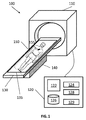
図1は、除神経による肺疾患の治療を一般に指向するシステム100を示す。システムは、治療装置110、治療台120、支持台130、および計算装置140を有する。治療装置110は、患者の身体の外側から肺の部分を非侵襲的に治療するよう、定位放射線療法(SBRT)のような放射線技術を使用してもよい。実施形態で、治療装置110は、高密度焦点式超音波療法(HIFU)、陽子線治療、および他の当業者に公知の肺疾患の非侵襲的治療に適切なもののような他の形態の医療技術またはエネルギーを使用してもよい。
FIG. 1 illustrates a
特に、システム100は、除神経の対象を識別および位置を解明するのに肺の3次元モデルを使用することにより、肺疾患を非侵襲的に治療する。システム100は、治療装置110、計算装置120、治療ベッド130、および支持台140を有する。患者150は治療ベッド130上に横たわり、治療装置110内へ入るのを待つ。
In particular, the
前述のように、治療装置110は、患者150の治療を可能にする、特に非侵襲性の方法で患者150の肺の治療を可能にする選択的なタイプである。言い換えれば、治療装置110は、治療エネルギーを放射し、対象に治療エネルギーを集中させる。よって、治療のために、患者150の組織の切開、および口、鼻、または身体の医療切開部を通したカテーテルの挿入は必要がない。
As described above, the
一部のケースで、治療装置110をまた本開示の実施形態による画像化装置として使用してもよい。画像化および治療の組み合わせを特徴とするそのような装置は、画像化装置から治療装置へ画像データを送出することに通常起因するエラー送出が少なく、また減少しえて、患者が画像化装置と治療装置の間の異なる場所にいることに通常起因する局在性エラーが少ないことが報告されてきた。さらに、患者150の部分(例えば肺)を、画像化した直後または同時に治療を行うことが可能でありうる。
In some cases, the
治療装置110をまた、継続処置またはフォローアップ処置に使用してもよい。例えばいくつかの状況で、1つまたは複数の神経の除神経治療がなされたら、治療された神経は完全に切断されず再生するかもしれない。この神経の不完全な切断は治療計画の一部かもしれず、または意図しないものかもしれない。この理由で、継続またはフォローアップ治療を行い、意図される治療効果を得るまたは維持するよう、追加の治療を以前に治療された神経に行ってもよい。
The
ラップトップ、デスクトップ、タブレット、または他の同様の計算装置のような計算装置120は、ディスプレイ122、1つまたは複数のプロセッサ124、メモリ126、ネットワークカード128、および入力装置129を有する。システム100はまた複数計算装置120を有してもよく、処置の計画および治療に個別の計算装置120を採用してもよい。ディスプレイ122はタッチ検知式および/または音声作動であってもよく、ディスプレイ122が入力装置および出力装置の両方として機能するのを可能にする。ディスプレイ122は、肺疾患の症状を示す肺の部分の位置を解明し識別する、肺の2次元または3次元モデルを表示してもよい。ディスプレイ122はさらに、治療される対象を選択、追加、および削除する選択肢、および治療のため設定可能な項目を表示してもよい。
A
1つまたは複数のプロセッサ124は、コンピュータ実行可能な命令を実行する。プロセッサ124は、肺の2次元または3次元モデルがディスプレイ122上に表示可能なように、画像処理機能を実行してもよい。実施形態で、1つまたは複数のプロセッサ124が他のプログラムに利用可能でありうるように、計算装置120はさらに、画像処理機能のみを実行する個別のグラフィックアクセラレータを有してもよい。
One or
メモリ126は、データおよびプログラムを格納する。例えばデータは、2次元または3次元モデルの画像データ、または患者の医療記録、処方箋、および/または患者の疾患の既往歴のようなあらゆる他の関連するデータであってもよい。メモリ126は、フラッシュメモリチップ、大容量記憶装置、テープドライブ、または記憶制御装置および通信バスを通してプロセッサに接続されるあらゆるコンピュータ可読な記憶媒体のような1つまたは複数の固体記憶装置を有してもよい。コンピュータ可読な記憶媒体は、コンピュータ可読な命令、データ構造、プログラムモジュールまたは他のデータのような情報記憶のあらゆる方法または技術で実行される、非一過性、揮発性および不揮発性、着脱可能および着脱不可能な媒体を含む。例えば、コンピュータ可読な記憶媒体は、ランダムアクセスメモリ(RAM)、読み出し専用メモリ(ROM)、消去可能プログラム可能読出専用メモリ(EPROM)、電気的消去可能プログラム可能読出専用メモリ(EEPROM)、フラッシュメモリまたは他の固体メモリ技術、CD−ROM、DVDまたは他の光学記憶装置、磁気カセット、磁気テープ、磁気ディスク記憶装置または他の磁気記憶装置、または所望の情報の格納に使用可能で、計算装置120によりアクセス可能なあらゆる他の媒体を含む。
The
前述のように、メモリ126内に格納されたプログラムの1つのタイプは、経路計画モジュールである。経路計画の最初のステップとして、患者の画像データ(通常はDCOMMフォーマット)が、例えばCT画像データセット(または他の画像化モダリティ)から経路計画モジュール内にインポートされる。画像化を、CT画像化、磁気共鳴画像法(MRI)、機能MRI、超音波画像化、X線、および/またはあらゆる他の画像化モダリティにより行ってもよい。
As mentioned above, one type of program stored in
経路計画モジュールプロセスは、患者の画像を処理し、CT画像の所望の部分、例えば、肺の3次元モデルを生成する。3Dモデルを生成するため、経路計画モジュールは、セグメンテーション、表面レンダリング、および/または体積レンダリングを採用する。これらのプロセスおよび経路計画モジュールの詳細は、同一出願人による米国特許出願第XX/XXX,XXX号(代理人整理番号H−IL−00099)、および米国特許出願第13/838,805号に見ることができ、これらの全体の内容が参照により本明細書に組み込まれる。そのような経路計画モジュールは、ユーザがCT画像データセットの個々のスライスを見て、1つまたは複数の対象を識別することを可能にする。これらの対象は、例えば肺疾患が肺機能または他を損なった組織の働きに影響する神経の病変または位置であってもよい。これらの対象を識別して、例えば生来の開口部または臨床医によりなされた切開口を通して生検または他のツールを伸ばすことにより対象に接近するか、または後述するように、治療装置110が採用可能なように、対象の位置を正確に示し対象の座標を識別するかのどちらかのために、経路計画モジュールは、ユーザが計画を立てるのを可能にする。経路計画モジュールは、一連のステップを通して、微細な解像度の画像を得るため、後の使用のための経路計画を立てるよう臨床医を導く。臨床医はディスプレイ装置122を介して経路計画モジュールと通信し、ディスプレイ装置122は臨床医からの入力を受信するため対話機能を表示する。経路計画モジュールを、除神経される神経の識別および位置を解明するよう、1つまたは複数の対象の解像度をさらに上げるために用いてもよい。臨床医の語は、内科医、外科医、看護師、医療助手、または医療処置の計画、実行、監視および/または監督に関与する経路計画モジュールのあらうるユーザを含む。
The path planning module process processes the patient image and generates a desired portion of the CT image, eg, a three-dimensional model of the lung. In order to generate a 3D model, the path planning module employs segmentation, surface rendering, and / or volume rendering. Details of these processes and path planning modules can be found in commonly assigned US patent application No. XX / XXX, XXX (Attorney Docket No. H-IL-00099) and US patent application No. 13 / 838,805. The entire contents of which are incorporated herein by reference. Such a path planning module allows a user to view individual slices of a CT image data set and identify one or more objects. These subjects may be, for example, neurological lesions or locations that affect the functioning of tissues in which lung disease impairs lung function or otherwise. Identify these subjects and approach them by extending a biopsy or other tool, for example through a natural opening or an incision made by a clinician, or the
ネットワークインタフェース128は、他の計算装置120および/または治療装置110が、有線および/または無線ネットワーク接続を通して互いに通信するのを可能にする。図1で、治療装置110は、医療画像、医療データおよび管理データを有線接続により計算装置120と送信または受信してもよい。ネットワークインタフェース128が他の計算装置120または治療装置110に無線で接続するケースで、ネットワークインタフェース128は、治療装置110が治療のために使用する周波数と異なる周波数を通信のために使用する。
The
入力装置129は、設定値、テキスト情報のようなデータまたは制御情報の入力、および/または治療装置110を制御するのに使用される。入力装置129は、キーボード、マウス、スキャン装置、または他のデータ入力装置を含む。
The
治療ベッド130は、治療される患者を受け入れる。支持台140は治療ベッド130を支持し、治療ベッド130を水平方向および垂直方向に移動可能な機械構造を有してもよい。例えば、患者が彼女の身体を治療台130の上に横たえるとき、治療される肺の対象が、治療のため最適な高さ、および治療装置110の下に位置するように、支持台140は治療台130の高さを調整し、治療台130を治療装置110の方へ、および治療装置110の方から移動する。
The
実施形態で、治療装置110がまた3次元モデルを作るための肺の画像化にも使用されるケースで、支持台140は、治療ベッド130を3つの横断方向、すなわち横断方向、冠状および矢状に移動してもよい。または、治療装置110は、3方向の患者の身体の画像のスライスを、患者160を移動せずにとるイメージングセンサを有してもよい。
In an embodiment, in the case where the
治療ベッド130は、場発生器135を有する。場発生器135を、多数の機能に用いてもよい。主な機能は、CT画像データ、特に経路計画のステップの間その中に識別される対象と治療ベッド130上に横たわる患者150の位置の位置合わせを可能にすることである。理解されるように、画像化および治療が異なる機械、異なる時間、または異なる場所で実行される場合、患者の中の適切な位置で治療が起こるのを確実にするため、患者と画像データの位置合わせが重要である。患者と画像データの位置合わせは、さまざまな方法で行ってもよい。
The
位置合わせの1つの方法論は、患者の気管支樹の2分岐点または3分岐点を通して、センサと共にプローブを横断することである。センサを、例えば気管支鏡に取り付けてもよい。センサは、場発生器135により生成された電磁場を検出し、その位置を表現する信号を出力する。この信号は、気管支鏡の画像データと、前述の経路計画のステップで生成された3Dモデルの内部の像を合わせる画像位置合わせソフトウェアと組み合わせて使用される。位置合わせプロセスにさまざまな因子が用いられ、その詳細は同一出願人による米国特許第8,218,846号に詳述され、その全体は参照により本明細書に組み込まれる。位置合わせされると、電磁場内の患者の位置は、経路計画の間に識別された対象の位置に対して識別され、対象の座標が治療の実行に使用可能である。
One methodology for alignment is to traverse the probe with the sensor through the bifurcation or trifurcation of the patient's bronchial tree. The sensor may be attached to a bronchoscope, for example. The sensor detects the electromagnetic field generated by the
実施形態で、患者160の呼吸運動が監視されるべきときは、治療の間患者の呼吸、特に、患者の移動を監視および把握できるように、場発生器135を患者150に位置付けた1つまたは複数のセンサと接続してもよい。例えば、移動追跡センサ155を、治療ベッド130または場発生器135と電磁的に接続してもよい。患者150が息を吸い、および息を吐くとき、肺をそれぞれ膨張または収縮するように、空気は肺に流入および流出する。移動追跡センサ155も従ってまた移動し、治療ベッド130に対する位置の変化を検出する。異なる身体の部分(例えば胸部の幅および深さ)の相対的な移動を考慮するよう、移動追跡センサ155を身体の少なくとも2つの部分に取り付けてもよい。
In an embodiment, when the respiratory motion of the patient 160 is to be monitored, one or more of the
移動追跡センサ155が実際には対象の神経の移動を追跡しないので、呼吸運動と対象の神経の運動を相互に関連付けるのに呼吸モデルが選択される。このようにして、除神経治療中対象の神経の正確な位置を識別しうるように、異なる身体の部分の移動が考慮され、CT画像に位置合わせされる。
Since the
実施形態で、場発生器135は治療ベッド130全体に及んでもよく、場発生器135の一部だけを監視できるように、そのような部分を起動してもよい。場発生器135は電磁場以外の場を生成してもよく、それを患者150に位置付けられたセンサの位置の監視に使用が可能であり、これは当業者に公知である。
In embodiments, the
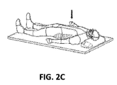
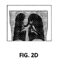
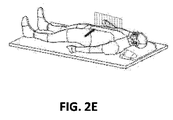
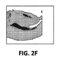
図2A〜図2Fは、対象を識別する有効な画像化モダリティの1つ、すなわちコンピュータ断層撮影(CT)技術を示す。診断ツールとしてのCT画像の使用は習慣となり、CTの結果は、しばしば対象の病変、腫瘍、または他の同様の目的となる対象のサイズおよび位置に関して臨床医が利用可能な主要な情報源である。CT画像は、横断方向、冠状方向および矢状方向のそれぞれの方向に患者をスライスでデジタル画像化することで通常得られる。例えば図2Aは、横断方向から撮られたCT画像のスライスを示す。言い換えれば、CT画像は、図2Bに示されるように、横断方向に垂直な、または患者の脊椎に垂直な平面で撮られた横断面図である。図2Cは、冠状方向から撮られたCT画像のスライスを示す。言い換えれば、CT画像は、図2Dに示されるように、冠状方向に垂直な平面で撮られた横断面図である。図2Eは、矢状方向から撮られたCT画像のスライスを示す。言い換えれば、CT画像は、図2Fに示されるように、矢状方向に垂直な平面で撮られた横断面図である。前述のように、経路計画段階の間、対象の識別または位置解明を試みるとき、臨床医はCT画像データをそれぞれの方向から1スライスずつ再検討してもよい。 2A-2F illustrate one effective imaging modality for identifying an object, the computed tomography (CT) technique. The use of CT images as a diagnostic tool has become a habit, and CT results are often the primary source of information available to clinicians regarding the size and location of a target lesion, tumor, or other similar target . CT images are usually obtained by digitally imaging the patient in slices in the transverse, coronal and sagittal directions. For example, FIG. 2A shows a slice of a CT image taken from the transverse direction. In other words, the CT image is a cross-sectional view taken in a plane perpendicular to the transverse direction or perpendicular to the patient's spine, as shown in FIG. 2B. FIG. 2C shows a slice of a CT image taken from the coronal direction. In other words, the CT image is a cross-sectional view taken on a plane perpendicular to the coronal direction, as shown in FIG. 2D. FIG. 2E shows a slice of a CT image taken from the sagittal direction. In other words, the CT image is a cross-sectional view taken on a plane perpendicular to the sagittal direction, as shown in FIG. 2F. As mentioned above, when attempting to identify or locate an object during the path planning phase, the clinician may review the CT image data one slice at a time from each direction.
実施形態で、3方向、すなわち、横断方向、冠状方向および矢状方向にとられた画像のこれらのスライスは、計算装置120に入力され、これが次に患者の肺の3次元モデルを生成する。通常、CT画像は、患者の身体内部の全ての器官の画像を含む。計算装置120は、大部分の器官の画像が3次元モデルに含まれるようにCT画像を処理する。3次元モデルは、肺、気管支樹、または気管の左葉および右葉のみを選択的に示してもよい。それでもなお、2次元画像(すなわち、CT画像)が、撮られたように画像を見るのに使用される。
In an embodiment, these slices of the image taken in three directions, i.e. transverse, coronal and sagittal, are input to the
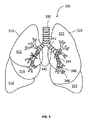
図3は、本開示の実施形態による特許の気管支樹および気管と肺の3次元モデルを示す。図3に示されるように、3次元モデルは、臨床医が特定の器官または対象の器官の一部を選択的に見られるように、大部分の器官の情報を有してもよい。このケースでは、これらの選択された器官は、右葉310、左葉320、気管330および気管支樹340を含む肺である。右葉310は3つの下位の葉、すなわち上葉312、中葉314および下葉316を有し、左葉320は2つの下位の葉、すなわち上葉322および下葉324を有する。
FIG. 3 shows a patent bronchial tree and a three-dimensional model of the trachea and lungs according to an embodiment of the present disclosure. As shown in FIG. 3, the three-dimensional model may have information on most organs so that the clinician can selectively view a particular organ or part of an organ of interest. In this case, these selected organs are the lungs including
気管330は、咽頭および喉頭を肺310および320につなぐ管である。気管330の下端で、左および右主気管支342は分岐される。葉気管支344もまた、主気管支342の下端で分岐する。主気管支342の円周は、葉気管支344のそれより大きい。同様に、区域気管支346が葉気管支344の下端で分岐し、終末細気管支348が区域気管支346の下端で分岐する。主気管支342、葉気管支344および区域気管支346は、軟骨板により支持される。しかし、区域気管支346のサイズがだんだん小さくなるとき、軟骨板は消滅し、外壁は平滑筋が優勢になる。終末細気管支348の外壁も平滑筋が優勢になる。
対象の神経は、あらゆる気管支樹、主気管支342、葉気管支344、区域気管支346、および終末細気管支348上にあるかもしれない。対象の除神経の効果は、症状の重症度または対象の神経の位置に基くかもしれない。肺疾患の症状が重症である場合、可塑性除神経を実行してもよく、症状が穏やかである場合、弾性除神経を実行してもよい。可塑性除神経は対象の神経の機能全体を停止し、弾性除神経は部分的に機能を停止する。対象の神経が主気管支342上に位置する場合、その対象の神経に結合し下位に位置する、続く葉気管支、区域気管支、終末細気管支上の神経の機能は全体的または部分的に停止されるかもしれない。同様に、対象の神経が終末細気管支348上に位置する場合、対象の神経の機能のみが全体的または部分的に停止されるが、対象の神経に結合および上位に位置する神経は、除神経により影響されることなくそれらの機能を良好に実行する。
The subject's nerves may be on any bronchial tree,
また、肺疾患の症状が重症である場合、治療の範囲は対象の神経のサイズより大きいかもしれないし、そうでない場合、治療の範囲は対象の神経のサイズに等しいかそれより小さいかもしれない。よって、対象の神経の治療の範囲は、肺疾患の症状の重症度、対象の神経の位置、および対象の神経のサイズによって決まる。 Also, if the symptoms of pulmonary disease are severe, the extent of treatment may be greater than the size of the subject's nerve, otherwise the extent of treatment may be less than or equal to the size of the subject's nerve. Thus, the scope of treatment of the subject's nerve depends on the severity of the symptoms of the pulmonary disease, the location of the subject's nerve, and the size of the subject's nerve.
いくつかの実施形態によると、選択された画像化モダリティが対象の神経の位置解明に十分な解像度を提供しないとき、画像のスライスをさらに微細にする必要がある。これは特に、区域気管支346または終末細気管支348を治療しようとするときに当てはまる。このケースでは、対象の神経を識別および位置解明可能であるように、他の画像化モダリティを使用して、さらに微細なスライスの解像度を提供してもよい。
According to some embodiments, when the selected imaging modality does not provide sufficient resolution for target nerve localization, the slice of the image needs to be further refined. This is especially true when trying to treat
1つの実施形態によると、患者150内の対象の神経の位置を識別するのに、より大きい特異性およびより大きい精度を提供するよう、超音波画像化モダリティを用いてもよい。1つのそのような実施形態で、前述の経路計画に従い放射状の超音波プローブが用いられ、経路の画像が撮られる。これらの画像を、CT画像データおよび/または3Dモデルのそれと位置合わせし、対象の神経の位置に関してより高い明瞭性を提供してもよい。例えばこのデータをまた、目標とする全てのありそうな対象が識別されたことを、臨床医が確認するのを診断上補助するよう使用してもよい。理解されるように、収集された第1の画像データ(例えば、CT画像データ)を増強するよう他の画像化モダリティを採用してもよく、これらのモダリティは、本開示の範囲から逸脱することなく、患者内部および外部の両方の種々の形態の超音波、磁気共鳴画像法(MRI)、蛍光透視検査、および他を含む。
According to one embodiment, an ultrasound imaging modality may be used to provide greater specificity and greater accuracy in identifying the location of the subject's nerve within the
図4は、本開示の実施形態による、対象を追加し、最終的に経路計画を立てる、経路計画モジュールのユーザ・インタフェース400を示す。臨床医が新しい経路計画を生成するよう選択すると、ディスプレイ上にユーザ・インタフェース400が表示される。ユーザ・インタフェース400は、小ウィンドウ410およびメインウィンドウ420を有する。
FIG. 4 illustrates a
小ウィンドウ410はスクリーンのメイン画像に直交の像を示し、ここではメイン像が軸方向の像であり、よって小ウィンドウは冠状の像であり、患者の肺の左葉および右葉412および位置バー414を示す。図4で示されるように、臨床医は位置バー414を垂直方向に移動することができ、それは、図2Aに示されるようにCT画像の軸方向のスライスを変更し、図2Bに示されるように軸方向に垂直な平面で撮られたCT画像をスクロールする影響を有する。臨床医はまた、あるいは代わりに、直接位置バー414を移動せずに、マウスホイールまたは他の装置のような入力装置によって患者の肺のCT画像をスクロールしてもよい。3次元モデルの表示の他の方向、例えば冠状方向が選択されたとき、小ウィンドウ410は治療を必要とする器官(ここでは肺として示す)の冠状の像を表示してもよい。小ウィンドウ414は、臨床医が現在見ているCTスライス430が、検討中の器官内でどこに位置するかについて、臨床医に全体的な参照をもたらす。小ウィンドウ414はまた、臨床医の参照のため、1つまたは複数の以前に識別された対象を表示してもよい。
メインウィンドウ420は、位置バー414が左葉および右葉412内に位置する平面で撮られたCT画像に対応する画像430を示す。タイトル432は、画像430が横断方向または軸方向の方向で撮られたCT画像であることを示す。日付および時間区域446は、CT画像430が撮られたときの日付および時間を示す。よって、臨床医は、対象の経路を計画するのに画像430が充分新しいかを判断可能である。臨床医が、画像430が経路計画のためには古過ぎると判断するケースでは、新しい3Dモデルおよび経路計画の作成のため、図2A〜図2Fに示されるような新しい画像を撮るべきである。
The
十字線434のような対象選択ツールが、臨床医が対象436を選択するのを補助する。方向標識438および440が、どの方向が右および左かを示す。図4に示されるように、方向標識438および440に基き、対象は肺の右葉内で選択される。
A subject selection tool such as a
ズームスライダバー442が、画像430の詳細または全体的な像を見るように、拡大表示および縮小表示するため使用される。例えば、ズームスライダバー442のずるいものが縮小アイコンに近い場合、画像430の特定の部分は縮小され、ズームスライダバー442のスライダが拡大アイコンに近い場合、画像430の特定の部分は拡大される。ウィンドウアイコン444を、対象436の選択サイズを微細にするのにズームスライダバー442と共に使用してもよい。対象436が対象選択434によって位置付けられているとき、臨床医はズームスライダバー442を使用して選択された領域を拡大し、ウィンドウアイコン444を用いて対象のウィンドウのサイズ変更および/または再配置を行うことにより、対象を詳しく識別してもよい。
A
対象436およびそのサイズが識別されたとき、臨床医は計画ボタン448をクリックして対象への経路計画を作成する。経路計画を、再検討&クリックボタン450をクリックすることにより、再検討およびエクスポートしてもよい。臨床医が経路計画が受け入れ可能と判断する場合、終了&エクスポートボタン452をクリックすることにより、経路計画は終了およびエクスポートされる。2つ以上の対象がある場合、臨床医は対象追加ボタン454をクリックし、前述と同様のことを行うことによってより多くの対象を追加可能である。経路を計画する詳細な方法は、同一出願人によるBakerの米国特許出願第13/838,805号、および米国特許出願第XX/XXX,XX号(代理人整理番号H−IL−00099)、ならびにその中で引用された参考文献に記載され、それらの全ては参照により本開示に組み込まれる。
When the subject 436 and its size are identified, the clinician clicks the
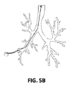
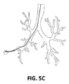
図5は、図3の気管支樹のような、肺の3次元モデルまたは画像のスライスの気管支樹の平面図を示す。対象の領域が図5Aの終末細気管支の下部左側の先端部に位置すると仮定すると、図5Bは、肺疾患の症状を示す肺の部分に対応する3次元モデルの対象の領域から、気管に対応する3次元モデルの第2の領域への経路を示す。図5Cは、3次元モデルの経路に従い対象へ患者の肺の内部に挿入された、超音波トランスデューサを示す。超音波トランスデューサが肺の部分に到達するとき、その領域の組織が明らかに画定可能で、最終的に対象周辺の除神経されるべき1つまたは複数の神経を位置解明および識別可能であるように、超音波トランスデューサは超音波を送信し、音波反射を受信する。このようにして、CT画像化モダリティおよび超音波画像化モダリティは、患者の肺内の除神経されるべき1つまたは複数の神経の充分に正確な位置を識別するのに十分な解像度をもたらす。 FIG. 5 shows a plan view of a bronchial tree of a three-dimensional model or image slice of the lung, such as the bronchial tree of FIG. Assuming that the region of interest is located at the lower left tip of the terminal bronchiole of FIG. 5A, FIG. 5B corresponds to the trachea from the region of interest of the three-dimensional model corresponding to the portion of the lung that exhibits symptoms of lung disease. The route to the 2nd field of the three-dimensional model to do is shown. FIG. 5C shows the ultrasound transducer inserted into the subject's lungs into the subject according to the path of the three-dimensional model. When the ultrasound transducer reaches a part of the lung, the tissue in that area can be clearly defined so that one or more nerves to be finally denervated around the subject can be located and identified The ultrasonic transducer transmits ultrasonic waves and receives acoustic reflections. In this way, CT imaging modalities and ultrasound imaging modalities provide sufficient resolution to identify a sufficiently accurate location of one or more nerves to be denervated within the patient's lungs.
図5Dおよび図5Eは、拡張作業経路510の遠位端部に位置する超音波トランスデューサ525を含む、拡張作業経路510を示す。超音波トランスデューサ525が肺組織の識別された部分に到達可能なように、臨床医は、図5Cに示される経路計画に従うことによって、気管支樹および気管の管腔の網状構造を操縦する。
5D and 5E show an
図5Eは、図5Dの円の領域530の拡大詳細図である。拡張ワーキングチャネル510または超音波トランスデューサ525の遠位先端部が管腔の網状構造を通して識別された部分へ操縦される一方で、超音波トランスデューサ525は、超音波を発して反射を受信し、管腔の網状構造および識別された部分の画像をとってもよく、それは画像のスライスより大きい解像度を有する。詳細は同一出願人による米国特許出願第13/836,203号に詳述され、その全体は参照により本開示に組み込まれる。
FIG. 5E is an enlarged detail view of the
図6は、図5AのA−Aの方向の終末細気管支の横断面図600である。終末細気管支は、柔らかい筋肉610に囲まれている。神経620および静脈630は、柔らかい筋肉の上に位置する。柔らかい筋肉610上の薄い神経620でさえも識別可能なように、超音波画像化モダリティは、前述のように終末細気管支の外部までもの気道の局部図を提供する。
6 is a
肺および肺に関連する組織は、常に運動している。あらゆる患者の身体の部分(例えば、肺,横隔膜、または血管組織)の移動、または臨床医のあらゆる操作上の移動(例えば、治療装置110または治療ベッド130)に比べると、神経620の厚さまたはサイズは比較的小さいので、結果として神経620は治療中に移動する。よって、対象の神経を正確に識別、位置解明、および治療するため、そのような移動は補正されるべきである。
The lungs and tissues associated with the lungs are constantly in motion. Compared to the movement of any patient body part (eg, lung, diaphragm, or vascular tissue), or any operational movement of a clinician (eg,
対象の神経620は、筋肉の収縮に介在するコリン作動性副交感神経、または弛緩に介在するアドレナリン作動性交感神経であってもよい。対象の神経620は、節前または節後神経であってもよい。
The
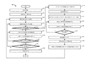
図7は、除神経により肺疾患を治療する治療計画の生成方法700を説明するフローチャートを示す。方法700は、1つまたは複数の対象の位置を解明および識別し、それから対象について治療計画を生成する。ステップ705で、臨床医は、検査、触診、打診、および/または聴診により、肺疾患を診断する。
FIG. 7 shows a flowchart illustrating a
肺疾患が診断された後、ステップ710で、例えばMRIまたはCT画像化装置を用いて、画像化装置が患者150の画像を撮る。一般的なMRIまたはCT画像化装置は、患者の画像を、3つの軸、すなわち、横断方向、冠状方向、および矢状方向に表示する。実施形態で、肺の位置を画像または視覚化のどちらかで識別するように、臨床医は画像増強剤を使用して、画像を撮る前に肺を蛍光性に染色してもよい。いくつかの画像増強剤は、脳の白質路(軸索)または灰白質核の視覚化を補助するように、軸索的、順行的または逆行的に移動可能であってもよい。言い換えれば、画像増強材は、気管支樹内および周辺に位置する神経の視覚化を補助してもよい。肺の画像が撮られるとき、蛍光マーカーが画像上に明らかに示されるように、これを肺の画像が撮られる前でさえ患者に与えてもよい。画像増強材は、蛍光染料またはFLUOROGOLD(登録商標)であってもよい。例えば、FLUOROGOLD(登録商標)は、神経の樹状突起を完全に着色する神経逆行性トレーサである。FLUOROGOLD(登録商標)が注入されるとき、神経は蛍光性に染色され、結果として光の特定の周波数によって刺激されたとき、蛍光の周波数を発する。このようにして、臨床医が明確に他の器官から神経を区別できるように、画像化装置または蛍光顕微鏡は、蛍光を検出する。本開示から逸脱することなく、当業者は神経組織の位置を識別する他のマーカーを採用しうる。
After the lung disease is diagnosed, at
ステップ715で、患者の肺気管支樹の3次元モデルを生成するため、これらの画像は組み合わせられ、処理される。通常、それぞれの方向で撮られた画像が多いほど、より微細なモデルを生成しうる。それでもなお、選択された画像モダリティの制限によって、ある場所ではスライス画像が多いことが3次元モデルの解像度の増強を補助しない。よって、最適数のスライス画像が、3方向のそれぞれで撮られ、画像化モダリティの仕様および必要とされる解像度の検討で予め決定される。
At
ステップ720で、臨床医は、3次元モデル/およびまたはMRIまたはCT画像を再検討し、疾患にかかり治療が必要な肺の部分を識別する。これは全体的な判断であり、肺の適切な部分に臨床医の意識を集中し、詳細に後述するようにそこでは特定の神経の識別が目的となり、治療される。
At
実施形態で、3次元モデルは、例えば心臓、肋骨、脊椎および肺、気管支樹および横隔膜といった、肺の中または周辺の内臓および他の生理機能の多くの情報を有しうる。臨床医は選択的に器官を見てもよく、対象の神経を治療する間、どちらが骨のような硬組織を避けるより適切な方向かを臨床医が決定可能なように、臨床医は3次元モデルをあらゆる方向の周辺に回転してもよい。3次元モデルの解像度によって、治療する神経がモデル内で視認可能でありえ、臨床医は、ツールを使用してユーザ・インタフェースで対象の治療のためにこれらの神経に印をつけることが可能である。そのような実施形態で、個々のCT画像を検討する必要はないかもしれない。 In an embodiment, the three-dimensional model may have a lot of information on internal organs and other physiology in or around the lung, such as the heart, ribs, spine and lung, bronchial tree and diaphragm. The clinician may selectively view the organs, and while treating the subject's nerves, the clinician will be able to determine which direction is better than avoiding hard tissue such as bone. The model may be rotated around any direction. Depending on the resolution of the three-dimensional model, the nerves to be treated can be visible in the model, and the clinician can use tools to mark these nerves for treatment of the subject at the user interface. . In such embodiments, it may not be necessary to review individual CT images.
ステップ725で、3次元モデルおよびCT画像が肺の識別された部分直近の対象の神経を識別するのに十分な解像度を有するかどうかが判断される。例えば、治療のための肺の識別された部分が1次または2次気管支樹上にある場合、そのとき3次元モデルおよびCT画像は、対象の神経を識別するのに十分な解像度を提供するかもしれない。しかし、識別された部分が3次気管支樹または気管支樹終端にある場合、3次元モデルおよびCT画像は、そのように行うのに十分な解像度を提供しないかもしれない。
At
3次元モデルおよびCT画像が十分な解像度を提供すると判断されるとき、ステップ748で臨床医は、識別された部分直近の治療される対象の神経を識別してもよい。対象の識別は、臨床医による画像および/または3次元モデル上の画像上の対象の配置をいう。画像および3次元モデル内の対象および特に対象の座標は、詳細に後述するように、治療装置を方向付けるのに使用される。 When it is determined that the 3D model and the CT image provide sufficient resolution, at step 748 the clinician may identify the nerve to be treated in the immediate vicinity of the identified portion. Object identification refers to the placement of objects on images and / or images on a three-dimensional model by a clinician. The objects in the image and the 3D model, and in particular the coordinates of the objects, are used to direct the treatment device, as will be described in detail below.
ステップ750で、位置マーカーまたは基準マーカーを、任意選択的に対象の神経直近の肺組織内に取り付けてもよい。通常、対象の神経の治療は、対象の神経の識別と異なる時点および場所で行われる。よって、後の検査または治療のための肺の他の画像化で、臨床医は対象の神経の位置を確認するかもしれない。このケースでは、位置マーカーは、肺疾患の症状を表す肺の部分直近の同一の位置に戻り臨床医を誘導するのに使用される。基準マーカーもまた、対象の神経の治療のための1つまたは複数の位置合わせプロセスで用いてもよい。実施形態で、治療のため後の時間に複数のマーカーを画像化するとき、臨床医が複数のマーカーの位相を示す画像に基き対象の神経のサイズおよび深さを識別しうるように、複数のマーカーを肺組織内に取り付けてもよい。
At
ステップ755で、肺疾患を患う肺の識別された部分内に対象とする神経がもっとあるかどうかが判断される。ステップ755で、識別された部分内に対象とする神経がもっとあると判断されるとき、対象とする神経がなくなるまで、ステップ748、750、および755が繰り返される。対象とする神経がもうないと判断されると、ステップ760で、臨床医はさらに、ステップ720で識別された肺の部分と異なる、肺疾患の症状を示す肺の部分がもっとあるかどうか判断する。部分がもっとあるとき、方法は、肺疾患の症状を示す部分がもうなくなるまで、ステップ720に戻る。
At
ステップ725で、3次元モデルおよび画像が対象の神経を識別するのに十分な解像度を提供しないと判断されるとき、さらに微細な画像を生成して対象の神経を識別するのに十分な解像度を提供するため、他の画像化モダリティが必要であるかもしれない。実施形態で、放射状超音波画像化モダリティが、肺の識別された部分のそのような解像度を提供しうる。識別された部分のそのような微細な画像を得るため、超音波画像化装置が識別された部分内へ挿入される。ここで、肺の識別された部分に到達するためにどの経路を超音波画像化装置がたどるべきか判断するのに、3次元モデルが使用される。そのような誘導を、経路計画と呼ぶ。
When it is determined in
ステップ730で、識別された部分のさらに微細な画像を得る選択肢としての経路計画は、超音波画像化装置の放射状超音波トランスデューサを識別された部分へ誘導するよう決定される。特許出願第13/838,805号に記載のように、これは参照により組み込まれるが、経路計画は、肺の識別された部分から始まり、口、鼻または切開部のような身体の開口部へ決定される。
At
ステップ732で患者を位置台におき、ステップ734で、臨床医は3次元モデルの経路計画に従うことにより放射状超音波トランスデューサを挿入し、身体の開口部から始まり肺の識別された部分で終了する。臨床医は、図1の計算装置120のメモリ126上に格納された経路計画モジュールを使用してもよい。放射状超音波トランスデューサが、経路計画の逆、すなわち身体の開口部から始まり肺の識別された部分への順番で、3次元モデルから決定された経路計画に従うことを、臨床医が確認可能なように、経路計画モジュールは、ディスプレイ装置122上に3次元モデルを表示する。
At
放射状超音波トランスデューサが肺の識別された部分へ到達するとき、放射状超音波トランスデューサは放射状に高周波数の音波を送信する。音波は、密度が変化する身体器官から反射する。ステップ736で、放射状超音波トランスデューサは音の反射を検出し、また検出された音の反射を放射状超音波画像化装置に送信し、放射状超音波画像化装置はそれから音の反射を処理し、画像を生成する。
When the radial ultrasonic transducer reaches the identified part of the lung, the radial ultrasonic transducer transmits high frequency sound waves radially. Sound waves reflect from body organs of varying density. At
実施形態で、肺の識別された部分の十分な解像度を提供するのに、近赤外、赤外、またはラマン光散乱に基いた組織分光法、光干渉断層撮影、共焦点マイクロ内視鏡検査、または蛍光マイクロ内視鏡検査を用いてもよい。さらに、神経の位置を分光学的に確認するため、FLUOROGOLD(登録商標)もまた使用してもよい。 In embodiments, tissue spectroscopy based on near infrared, infrared, or Raman light scattering, optical coherence tomography, confocal microendoscopy to provide sufficient resolution of the identified portion of the lung Alternatively, fluorescent microendoscopy may be used. In addition, FLUOROGOLD® may also be used to spectroscopically confirm the location of the nerve.
ステップ738で、臨床医は、放射状の超音波を用いて画像化された領域直近に位置マーカーを取り付けてもよい。これらの位置マーカーは、後の使用のため対象の神経の位置をおおまかに識別するのを補助する。ステップ750のように、位置を識別するのに複数の位置マーカーを使用してもよい。位置マーカーが放射状の超音波画像化が行われるそれぞれの領域に取り付けられるように、マーカーを、画像が撮られている間に同時に、または代わりに画像化およびマーカー配置がとられる繰り返し処理の一部として、取り付けてもよい。少なくとも、位置マーカーは、CT画像または3次元モデル内で予め識別された肺疾患を患う肺組織の部分内または周辺に取り付けられる。
At
対象は神経の長さに沿った1つまたは複数の箇所であってもよく、対象が1つの平面、例えば気管支樹の円周上の神経の長さに沿って先へ、または異なる平面の長さに沿って先へ異なる距離で互いから離れて位置することを意味する。 The subject may be one or more locations along the length of the nerve, and the subject may move forward along the length of the nerve on one plane, eg, the circumference of the bronchial tree, or the length of a different plane It means to be located away from each other at different distances along the length.
ステップ740で、放射状の超音波で画像化する肺組織の部分がもっとあるかどうか判断される。画像化する部分がもっとあると判断されるとき、画像化を必要とする部分がなくなるまで、生成された超音波画像を用いてステップ736および738が繰り返される。肺の全ての部分が放射状の超音波を用いて画像化されると、ステップ742で放射状の超音波画像は計算装置120へエクスポートされ、メモリ126内に格納される。
At
この時点で、臨床医はすべき判断がある。ステップ736で撮られた放射状の超音波画像は、ステップ710で撮られた元のCT画像より局在化された詳細を提供する。よって放射状の超音波画像を、CT画像と位置合わせおよび組み合わせて、高解像度の画像セットを生成してもよい。なされるべき判断は、ステップ744で新しいCT画像を生成するかどうかである。利点は、新しいCT画像を生成することにより、ステップ738で取り付けられた基準マーカーもまたこの時点で画像化され、位置合わせにより大きい可能性をもたらし、患者の治療計画および治療の両方について対象の位置を明瞭に識別することである。しかし、一部のケースで、第2のCT画像化ステップをやめて、ステップ736で生成された超音波画像を、ステップ710で生成された元のCT画像と単に位置合わせすることで十分かもしれない。従って、ステップ710の元のCT画像を使用するのであろうと、ステップ744で新しく生成されたCT画像を使用するのであろうと、CT画像および超音波画像は互いに位置合わせされ、ステップ746で高解像度の画像セットが生成される。
At this point, the clinician has a decision to make. The radial ultrasound image taken at
処理ループは、ステップ746から3次元モデルが生成されるステップ715へ戻るが、今回は高解像度の画像セットを使用する。このプロセスは前述のようにステップ760を通って続き、ステップ755および760で再検討される神経および肺組織の部分がもうないと判断されるまで、高解像度の画像セット内の対象の神経の位置を識別する。
The processing loop returns from
ステップ755で識別する神経がもうなく、ステップ760で肺t再検討の部分がもうないと判断されるとき、ステップ765で治療計画が生成される。治療計画は、その方法で識別される全ての対象の治療に必要がある情報を含む。例えば治療計画は、それぞれの対象の神経のサイズ、深さ、および位置を有してもよい。それぞれの対象の神経の情報に基き、治療計画はそれぞれの対象の治療方法についての運用上の情報をさらに含んでもよい。運用上の情報は、放射されるエネルギー量、治療期間、治療ベクトル、および対象の神経の除神経の治療数を有してもよい。治療期間は、治療装置が組織にエネルギーを加える間の期間である。治療期間の間の治療ベクトルにおけるエネルギー量の放射を、意図される対象以外に組織を傷つける可能性が低いように決定してもよい。ここで治療ベクトルは、治療エネルギーが対象の神経に放射される角度であってもよい。対象の神経のサイズまたは深さが所定のサイズより大きいまたは深いとき、対象の神経を十分に治療するのに複数の治療が必要であるかもしれない。個別の治療は意図された対象の神経以外の組織を傷付けないけれども、同一の位置の複数の治療は意図された対象の神経以外の組織を傷付けるかもしれない。よって、複数の治療の間治療エネルギーが1つの角度のみによって放射されないように、治療ベクトルは、複数の治療の場合一連の角度を有してもよい。治療計画は、肺疾患の重症度によって変わってもよい。対象の神経の治療の間、硬組織または骨のようないくつかの組織は、治療エネルギーを吸収または反射するかもしれない。そのような治療エネルギーの吸収または反射は、効果のない治療の原因となり、または対象の神経以外のいくつかの組織を傷付ける結果になるかもしれない。よって治療計画は、これらの構造からの干渉がありうる範囲を避けて立てなければならない。
When it is determined in
3次元モデルを、治療ベクトルの決定に使用してもよい。3次元モデルは器官の大部分を有し、あらゆる方向に回転可能であるので、臨床医は、器官を選択的に見て3次元モデルをあらゆる方向に回転することにより、治療ベクトルを決定してもよい。実施形態で、3次元モデルを、1つの対象の神経に対し複数単位の操作のためのいくつかの治療ベクトルを自動的に提供するよう使用してもよい。生成されると、この治療計画をメモリ装置126、または患者の治療に使用する治療装置110へ直接エクスポート可能である。
A three-dimensional model may be used to determine the treatment vector. Since the 3D model has the majority of the organ and can rotate in any direction, the clinician can determine the treatment vector by selectively viewing the organ and rotating the 3D model in any direction. Also good. In embodiments, a three-dimensional model may be used to automatically provide several treatment vectors for multiple units of manipulation for a single target nerve. Once generated, this treatment plan can be exported directly to the
実施形態で、神経機能画像化モダリティを使用して、肺の識別された部分の十分な解像度を提供してもよい。神経機能画像化モダリティは、長い神経路または軸索に沿って順行または逆行で白質の画像を生成し、またMRIまたはCT画像と位置合わせしてもよい。臨床医は対象の神経のサイズを識別し、サイズに基き治療期間およびエネルギーを含む治療計画を作成してもよい。 In an embodiment, a neural function imaging modality may be used to provide sufficient resolution of the identified portion of the lung. Neural functional imaging modalities may produce white matter images in a forward or reverse fashion along a long neural tract or axon and may be aligned with MRI or CT images. The clinician may identify the size of the target nerve and create a treatment plan that includes treatment duration and energy based on the size.
図8は、対象の神経を治療する方法800を説明するフローチャートを示す。810で臨床医は、3次元モデル、画像(CT、超音波、および高解像度画像セットを含む)と共に治療計画を治療装置へインポートする。ステップ815で、患者が図1の治療ベッド130上に配置される。治療装置110が画像化装置でもある場合、ステップ820で臨床医は患者の肺のフォローアップ画像化を実行してもよく、このフォローアップ画像化を、位置合わせの目的で治療装置に対して患者150の位置を決定するのに使用してもよい。治療装置が治療ベッドおよび患者150に対して場所内の対象の神経の位置を決定可能なように、臨床医は、位置マーカーを見て治療装置上の患者の位置(すなわち現在の画像)を従来の画像と位置合わせすることにより、新しいセットの画像を予め撮られた画像(例えば以前のCT画像または解像度を強化した画像)と比較する。ステップ820は任意であり、図1の場発生器135からの電磁提出発出を検出するよう気管支鏡内に設置されたセンサで気管支鏡検査処置を実行することを含む、当業者に公知である患者を治療装置に位置合わせする他の方法がある。患者および治療ベッドに対するセンサの相対的な位置が、CTまたは解像度を強化した画像に位置合わせ可能なように、生成された場が気管支鏡内のセンサ(図示せず)により検出される。ここで、場発生器により生成された場は電磁場であってもよく、またはセンサが治療ベッドに対してその位置を検出可能であるように、当業者が実行可能な他の場であってもよい。このようにして、場所内の患者の位置を、治療装置が治療装置内の対象の神経の位置を識別および照合可能なように補正してもよい。追加の画像が撮られたかどうかにかかわらず、ステップ825で、治療装置110上の場所内の患者の位置が、治療計画に位置合わせされる。
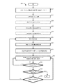
FIG. 8 shows a flowchart illustrating a
ステップ830で、1つまたは複数の移動追跡センサを任意選択的に患者に取り付け、患者の移動を追跡してもよい。移動追跡センサは、場発生器135により生成された場を検出可能なセンサであってもよい。患者は治療ベッド上に配置されるが、患者の肺は、呼吸、横隔膜のような他の器官の移動、または患者の移動によって移動する。そのような移動を、実際の治療の開始前に検討および補正すべきである。移動追跡センサは、基準マーカー、位置センサ、またはビーコンであってもよい。肺の移動は、呼吸運動、心臓運動、および/または患者の移動により引き起こされうる。治療台に対する患者の移動が記録されうるように、移動追跡マーカーを治療ベッドと電磁的に接続してもよい。
At step 830, one or more movement tracking sensors may optionally be attached to the patient to track patient movement. The movement tracking sensor may be a sensor capable of detecting the field generated by the
移動追跡センサを患者の身体に取り付けてもよいケースで、患者の呼吸パターンおよび肺の移動に適合する呼吸モデルを見つけるよう、2つ以上の移動追跡センサを取り付けてもよい。呼吸モデルは、肺の移動と患者の呼吸パターンの間の関係を示す。患者が呼吸している間の3次気管支樹または気管支樹の末端の正確な推測は、全体的な呼吸モデルによっては容易に得られないかもしれない。呼吸は肺が循環的に動く原因となり、患者のサイズ、年齢、標高、健康状態などといったそのような呼吸特性によって、呼吸サイクルの間振幅および方向により肺の移動は5mmから30mm変わるからである。米国PCT国際出願第PCT/IB2008/003728号は、その全体が本明細書に参照により組み込まれるが、患者の呼吸サイクルの間小さな気管支樹の移動を正確に推測可能な、動的呼吸モデルの構築方法を記載する。 In cases where a movement tracking sensor may be attached to the patient's body, two or more movement tracking sensors may be attached to find a breathing model that matches the patient's breathing pattern and lung movement. The respiratory model shows the relationship between lung movement and the patient's respiratory pattern. An accurate guess of the tertiary bronchial tree or the end of the bronchial tree while the patient is breathing may not be readily available with the overall respiratory model. Respiration causes the lungs to move cyclically, and depending on such respiratory characteristics such as patient size, age, elevation, health status, etc., lung movement varies from 5 mm to 30 mm depending on the amplitude and direction during the respiratory cycle. US PCT International Application No. PCT / IB2008 / 003728, which is incorporated herein by reference in its entirety, builds a dynamic breathing model that can accurately infer small bronchial tree movements during a patient's breathing cycle. Describes the method.
呼吸モデルに基き、臨床医は、患者が呼吸している間の肺の移動を推測してもよい。吸入が胸部を拡大して、胸部の深さおよび幅が増加することを意味し、呼気が胸部を収縮させるので、治療ベッドに関連して胸部の深さおよび幅の変化を追跡するのに、少なくとも2つの移動追跡センサが、1つは深さについて、他の1つは幅について必要である。 Based on the breathing model, the clinician may infer lung movement while the patient is breathing. Inhalation means expanding the chest and increasing the depth and width of the chest, and exhalation causes the chest to contract, so to track changes in the depth and width of the chest relative to the treatment bed, At least two movement tracking sensors are required, one for depth and the other for width.
移動追跡センサの出力は、それから治療装置へ送信される。ステップ835で、治療装置が呼吸サイクルの間治療ベッドに対して対象の神経を識別および位置解明しうるように、治療装置は患者の移動を補正する。
The output of the mobile tracking sensor is then transmitted to the treatment device. At
実施形態で、3次元モデルが治療の関連情報を有するとき、治療の評価において臨床医を補助するよう、移動情報を3次元モデル内に表示してもよい。このケースでは、3次元モデルを、対象の神経の治療の終了までずっと使用してもよい。 In an embodiment, when the 3D model has treatment related information, movement information may be displayed in the 3D model to assist the clinician in evaluating the treatment. In this case, the 3D model may be used all the way to the end of treatment of the subject's nerve.
ステップ840で、臨床医は、呼吸サイクルの間で治療を開始する開始時間を決定可能である。治療計画に含まれる治療時間は、開始時間から始まる。肺の対象の神経は、開始時間から始めて操作時間の間最も少なく移動する。治療期間は、患者がほぼ呼気を完了する時間から患者が吸入をほぼ開始する時間までの時間、または患者がほぼ吸入を完了する時間から患者が呼気をほぼ開始する時間までの時間より少ないか等しいかもしれない。治療期間は、患者が息を止める間であってもよい。治療計画方法700で決定された治療期間が、肺が最も少なく移動する時間の間より長い場合、いくつかの治療を用いてもよく、調整された操作情報が患者の治療に適用可能であるように、患者の呼吸モデルまたはパターンに基き治療ベクトルを調整してもよい。
At
ステップ845で、治療ベッドまたは治療装置は、治療計画により治療が実行可能となるように移動する。例えば、対象の神経の位置が右肺の上葉にある場合、対象の神経が治療装置の下になるように、治療ベッドは横方向に移動してもよい。または対象の神経に関する治療角度が右手側から30度の角度である場合、治療装置がその角度で対象の神経を治療するように、治療装置は横方向の周辺を回転してもよい。これを行う間、臨床医は、治療装置内の対象の位置合わせされた位置が、治療ベッドに対する対象の実際の位置に合致することを照合および確認すべきである。
At
ステップ850で、肺の識別された対象の神経の機能が影響を受けるように、除神経治療が開始時間から開始して操作期間中実行される。臨床医は、操作ベクトルで定義された角度で対象の神経を除神経するため、SBRTを使用して患者の身体の外側から定位放射線を放射してもよい。または、あらゆる他の非侵襲性治療技術を採用してもよい。そのような治療は、肺疾患の重症度に基き、可塑性除神経または弾性除神経であってもよい。
At
ステップ855で、対象の神経が充分治療されたかどうか判断される。決定を、対象の神経のリアルタイムの画像化に基き、または対象の治療容積、加えられたエネルギー量、および治療の持続時間に関する計算に基き行ってもよい。対象の神経が充分治療されていない場合、対象の神経が充分治療されるまで他の除神経プロセスが実行される。このケースでは、連続した治療が、治療計画に含まれる操作ベクトルに挙げられた角度、エネルギー量および/または操作時間の変更によって対象の神経以外の組織を傷つけうることがないように、対象の神経の治療計画をまた調整してもよい。ここで、治療は、治療効果の促進または医療コンプライアンスの欠如の補正のために、医療治療(例えば、SPIRIVA(登録商標)または肺機能の薬物治療)と併せて使用してもよい。
In
対象の神経が充分治療された場合、ステップ860で、臨床医は治療計画に治療されていない対象の神経があるかどうか判断する。ステップ860で治療計画に対象の神経がもうない場合、全ての対象の神経の治療は完了である。治療されていない対象の神経がある場合、ステップ865で、他の対象の神経について治療ベクトルの変更が必要かどうかさらに判断される。新しい対象の神経が以前に治療された対象の神経と異なる位置にあるとき、または新しい対象が以前に治療された対象の神経と異なる角度で治療されるとき、これは起こりうる。必要である場合、治療方法はステップ835へ戻り、新しい対象の神経を含む肺の異なる部分は以前の対象の神経を含む肺の部分と異なって移動するかもしれないので、患者の移動を補正する。必要でない場合、治療方法はステップ850へ戻り、新しい対象の神経を非侵襲的に治療する。
If the subject's nerve has been sufficiently treated, at
例示および説明の目的で添付の図を参照して実施形態を詳細に記載したが、本発明のプロセスおよび機器はそれによって限定されるものと解釈するべきではないことを理解すべきである。前述の実施形態への種々の改良が開示の範囲から逸脱することなくなされうることが、当業者に明らかになるであろう。 Although embodiments have been described in detail with reference to the accompanying drawings for purposes of illustration and description, it is to be understood that the process and apparatus of the present invention should not be construed as limited thereby. It will be apparent to those skilled in the art that various modifications to the embodiments described above can be made without departing from the scope of the disclosure.
Claims (21)
アプリケーションを実行、および前記画像の第1のセットでとられた前記肺の部分の3次元モデルを生成するよう構成されたプロセッサと、
前記画像の第1のセットでとられた前記部分直近の対象の神経を位置解明するため、
ユーザが前記画像の第1のセットおよび前記3次元モデルを再検討するのを可能にするユーザ・インタフェースを表示するディスプレイと、
前記肺の部分の機能が影響を受けるように、前記3次元モデルおよび前記画像の第1のセットから立てられた治療計画に基き、前記対象の神経を非侵襲的に除神経するよう構成された治療装置と、を備える、
肺神経の識別および除神経システム。 A memory configured to accept a first set of images of at least a portion of the lung showing symptoms of lung disease;
A processor configured to execute an application and generate a three-dimensional model of the portion of the lung taken with the first set of images;
In order to localize the nerves of the nearest object taken in the first set of images,
A display that displays a user interface that allows a user to review the first set of images and the three-dimensional model;
Based on a treatment plan established from the three-dimensional model and the first set of images, the nerve of the subject is configured to be denervated non-invasively so that the function of the lung portion is affected. A treatment device,
Pulmonary nerve identification and denervation system.
呼吸モデルが、前記患者の前記移動に基き生成され、
前記治療装置が、前記呼吸モデルに基き前記対象の神経の位置を追跡することにより、前記対象の神経の移動について補正する、
請求項1に記載のシステム。 A movement tracking sensor configured to track the movement of the patient;
A breathing model is generated based on the movement of the patient;
The therapeutic device corrects for movement of the target nerve by tracking the position of the target nerve based on the respiratory model;
The system of claim 1.
前記移動追跡センサが、前記患者に取り付けられ、治療ベッドと電磁的に接続されて前記患者の呼吸サイクルの間前記治療ベッドに対する前記患者の移動を監視し、
前記呼吸モデルが、前記患者の呼吸サイクルの間の前記移動追跡センサの移動に基く、
請求項11に記載のシステム。 A treatment bed on which the patient is placed,
The movement tracking sensor is attached to the patient and electromagnetically connected to the treatment bed to monitor movement of the patient relative to the treatment bed during the patient's respiratory cycle;
The breathing model is based on movement of the movement tracking sensor during the patient's breathing cycle;
The system of claim 11.
請求項1に記載のシステム。 The three-dimensional model is a first of the images taken by one or more imaging devices selected from the group consisting of computed tomography (CT), magnetic resonance imaging (MRI), and ultrasound imaging devices. Generated from a set of ones,
The system of claim 1.
前記超音波画像化装置が患者内に挿入されると、前記超音波画像化装置は前記肺疾患の症状を示す肺の少なくとも部分を画像化するように前記経路に従う、
請求項15に記載のシステム。 The processor executes an application for determining and displaying a path for the portion of the lung based on the three-dimensional model and the first set of images;
When the ultrasound imaging device is inserted into a patient, the ultrasound imaging device follows the pathway to image at least a portion of the lung exhibiting symptoms of the lung disease.
The system according to claim 15.
前記プロセッサが、前記超音波画像と前記画像の第2の画像セットを組み合わせる
アプリケーションを実行し、ユーザが前記組み合わせた画像に基いて除神経についての対象の神経を識別するのを可能にするよう構成された、
請求項17に記載のシステム。 The memory is configured to accept a second image set of images of at least a portion of the lung exhibiting symptoms of lung disease;
The processor is configured to execute an application that combines the ultrasound image and a second image set of the images to allow a user to identify a target nerve for denervation based on the combined image. Was
The system of claim 17.
Applications Claiming Priority (5)
| Application Number | Priority Date | Filing Date | Title |
|---|---|---|---|
| US201361762741P | 2013-02-08 | 2013-02-08 | |
| US61/762,741 | 2013-02-08 | ||
| US201461936933P | 2014-02-07 | 2014-02-07 | |
| US61/936,933 | 2014-02-07 | ||
| PCT/US2014/015281 WO2014124241A1 (en) | 2013-02-08 | 2014-02-07 | System and method for lung denervation |
Publications (2)
| Publication Number | Publication Date |
|---|---|
| JP2016511027A true JP2016511027A (en) | 2016-04-14 |
| JP2016511027A5 JP2016511027A5 (en) | 2017-03-09 |
Family
ID=51297898
Family Applications (1)
| Application Number | Title | Priority Date | Filing Date |
|---|---|---|---|
| JP2015557114A Pending JP2016511027A (en) | 2013-02-08 | 2014-02-07 | Lung denervation system and method |
Country Status (6)
| Country | Link |
|---|---|
| US (3) | US10328281B2 (en) |
| JP (1) | JP2016511027A (en) |
| CN (1) | CN104994783B (en) |
| AU (1) | AU2014214766B2 (en) |
| CA (1) | CA2899514A1 (en) |
| WO (1) | WO2014124241A1 (en) |
Cited By (2)
| Publication number | Priority date | Publication date | Assignee | Title |
|---|---|---|---|---|
| JP2020036758A (en) * | 2018-09-04 | 2020-03-12 | 株式会社日立製作所 | Position measurement device, treatment system comprising the same, and position measurement method |
| WO2024117129A1 (en) * | 2022-11-29 | 2024-06-06 | 東芝エネルギーシステムズ株式会社 | Medical image processing device, treatment system, medical image processing method, and program |
Families Citing this family (20)
| Publication number | Priority date | Publication date | Assignee | Title |
|---|---|---|---|---|
| ATE494040T1 (en) | 2006-06-28 | 2011-01-15 | Ardian Inc | SYSTEMS FOR HEAT-INDUCED RENAL NEUROMODULATION |
| JP6046041B2 (en) | 2010-10-25 | 2016-12-14 | メドトロニック アーディアン ルクセンブルク ソシエテ ア レスポンサビリテ リミテ | Devices, systems, and methods for neuromodulation therapy evaluation and feedback |
| US10328281B2 (en) | 2013-02-08 | 2019-06-25 | Covidien Lp | System and method for lung denervation |
| US9639666B2 (en) | 2013-03-15 | 2017-05-02 | Covidien Lp | Pathway planning system and method |
| US10433902B2 (en) | 2013-10-23 | 2019-10-08 | Medtronic Ardian Luxembourg S.A.R.L. | Current control methods and systems |
| US10610292B2 (en) | 2014-04-25 | 2020-04-07 | Medtronic Ardian Luxembourg S.A.R.L. | Devices, systems, and methods for monitoring and/or controlling deployment of a neuromodulation element within a body lumen and related technology |
| EP3943032A1 (en) | 2014-11-14 | 2022-01-26 | Medtronic Ardian Luxembourg S.à.r.l. | Catheter apparatuses for modulation of nerves in communication with the pulmonary system and associated systems |
| JP2016099665A (en) * | 2014-11-18 | 2016-05-30 | 株式会社東芝 | Viewpoint position calculation device, image generation device, viewpoint position calculation method, image generation method, viewpoint position calculation program, and image generation program |
| US10327853B2 (en) | 2016-05-10 | 2019-06-25 | Covidien Lp | System and method of performing treatment along a lumen network |
| US10952799B2 (en) | 2017-05-31 | 2021-03-23 | Covidien Lp | Systems and methods for navigational bronchoscopy and selective drug delivery |
| US10534962B2 (en) * | 2017-06-17 | 2020-01-14 | Matterport, Inc. | Automated classification based on photo-realistic image/model mappings |
| CN107096135A (en) * | 2017-06-22 | 2017-08-29 | 苏州奥特科然医疗科技有限公司 | Mobile detecting system and method |
| US12082917B2 (en) | 2018-01-24 | 2024-09-10 | Medtronic Ireland Manufacturing Unlimited Company | Systems, devices, and methods for assessing efficacy of renal neuromodulation therapy |
| US11344356B2 (en) | 2018-02-28 | 2022-05-31 | Medtronic Cryocath Lp | Apparatus and method for targeted bronchial denervation by cryo-ablation |
| US11944388B2 (en) | 2018-09-28 | 2024-04-02 | Covidien Lp | Systems and methods for magnetic interference correction |
| CN110013269A (en) * | 2019-04-08 | 2019-07-16 | 夏丽 | A kind of ultrasound monitoring surgical operation care device |
| CN110037699B (en) * | 2019-04-23 | 2024-01-19 | 上海联影医疗科技股份有限公司 | Method for scanning by using magnetic resonance system |
| EP4041311A4 (en) * | 2019-10-10 | 2024-02-21 | Alume Biosciences, Inc. | Methods and systems using peptides for targeting and mapping human nerves in image guided surgery, diagnostics and therapeutic delivery |
| US11666370B2 (en) | 2020-07-27 | 2023-06-06 | Medtronic, Inc. | Apparatus and method for targeted temporary bronchial nerve modulation by cryo-ablation for prevention and treatment of acute respiratory distress syndromes |
| US20220370143A1 (en) * | 2021-05-20 | 2022-11-24 | Acclarent, Inc. | Registration probe for enhanced information capture |
Citations (6)
| Publication number | Priority date | Publication date | Assignee | Title |
|---|---|---|---|---|
| US5754623A (en) * | 1994-03-25 | 1998-05-19 | Kabushiki Kaisha Toshiba | Radiotherapy system |
| JP2005514969A (en) * | 2001-06-08 | 2005-05-26 | カリプソー メディカル テクノロジーズ インコーポレイテッド | Guided radiation therapy system |
| WO2011046880A2 (en) * | 2009-10-12 | 2011-04-21 | Kona Medical, Inc. | Energetic modulation of nerves |
| US20110118725A1 (en) * | 2009-11-11 | 2011-05-19 | Mayse Martin L | Non-invasive and minimally invasive denervation methods and systems for performing the same |
| JP2012210232A (en) * | 2009-08-19 | 2012-11-01 | Mitsubishi Electric Corp | Radiation treatment system |
| WO2013011733A1 (en) * | 2011-07-15 | 2013-01-24 | 株式会社 日立メディコ | Endoscope guidance system and endoscope guidance method |
Family Cites Families (29)
| Publication number | Priority date | Publication date | Assignee | Title |
|---|---|---|---|---|
| US5845636A (en) | 1989-05-19 | 1998-12-08 | Puritan Bennett Corporation | Method and apparatus for maintaining patient airway patency |
| US5217456A (en) * | 1992-02-24 | 1993-06-08 | Pdt Cardiovascular, Inc. | Device and method for intra-vascular optical radial imaging |
| US5553618A (en) * | 1993-03-12 | 1996-09-10 | Kabushiki Kaisha Toshiba | Method and apparatus for ultrasound medical treatment |
| US7027869B2 (en) | 1998-01-07 | 2006-04-11 | Asthmatx, Inc. | Method for treating an asthma attack |
| US6634363B1 (en) | 1997-04-07 | 2003-10-21 | Broncus Technologies, Inc. | Methods of treating lungs having reversible obstructive pulmonary disease |
| IL122578A (en) * | 1997-12-12 | 2000-08-13 | Super Dimension Ltd | Wireless six-degree-of-freedom locator |
| US8181656B2 (en) | 1998-06-10 | 2012-05-22 | Asthmatx, Inc. | Methods for treating airways |
| IL126333A0 (en) * | 1998-09-24 | 1999-05-09 | Super Dimension Ltd | System and method of recording and displaying in context of an image a location of at least one point-of-interest in body during an intra-body medical procedure |
| DE10357184A1 (en) * | 2003-12-08 | 2005-07-07 | Siemens Ag | Combination of different images relating to bodily region under investigation, produces display images from assembled three-dimensional fluorescence data image set |
| US8437449B2 (en) * | 2004-07-23 | 2013-05-07 | Varian Medical Systems, Inc. | Dynamic/adaptive treatment planning for radiation therapy |
| US8095203B2 (en) * | 2004-07-23 | 2012-01-10 | Varian Medical Systems, Inc. | Data processing for real-time tracking of a target in radiation therapy |
| WO2006116198A2 (en) | 2005-04-21 | 2006-11-02 | Asthmatx, Inc. | Control methods and devices for energy delivery |
| US20070265521A1 (en) * | 2006-05-15 | 2007-11-15 | Thomas Redel | Integrated MRI and OCT system and dedicated workflow for planning, online guiding and monitoring of interventions using MRI in combination with OCT |
| WO2008005953A2 (en) | 2006-06-30 | 2008-01-10 | Broncus Technologies, Inc. | Airway bypass site selection and treatment planning |
| EP2086399B1 (en) * | 2006-11-10 | 2017-08-09 | Covidien LP | Adaptive navigation technique for navigating a catheter through a body channel or cavity |
| EP2192855B1 (en) | 2007-07-09 | 2020-03-25 | Covidien LP | Patent breathing modeling |
| US8235983B2 (en) | 2007-07-12 | 2012-08-07 | Asthmatx, Inc. | Systems and methods for delivering energy to passageways in a patient |
| KR101719824B1 (en) | 2008-05-09 | 2017-04-04 | 호라이라 인코포레이티드 | Systems, assemblies, and methods for treating a bronchial tree |
| US8218846B2 (en) * | 2008-05-15 | 2012-07-10 | Superdimension, Ltd. | Automatic pathway and waypoint generation and navigation method |
| EP2293720B1 (en) * | 2008-06-05 | 2021-02-24 | Varian Medical Systems, Inc. | Motion compensation for medical imaging and associated systems and methods |
| US20120063644A1 (en) * | 2009-06-01 | 2012-03-15 | Koninklijke Philips Electronics N.V. | Distance-based position tracking method and system |
| US9174065B2 (en) | 2009-10-12 | 2015-11-03 | Kona Medical, Inc. | Energetic modulation of nerves |
| AU2010319477A1 (en) * | 2009-11-11 | 2012-05-24 | Holaira, Inc. | Systems, apparatuses, and methods for treating tissue and controlling stenosis |
| WO2011088399A1 (en) * | 2010-01-18 | 2011-07-21 | Stanford University | Method and apparatus for radioablation of regular targets such as sympathetic nerves |
| AU2011237666A1 (en) * | 2010-04-06 | 2012-11-08 | Holaira, Inc. | System and method for pulmonary treatment |
| US9089340B2 (en) * | 2010-12-30 | 2015-07-28 | Boston Scientific Scimed, Inc. | Ultrasound guided tissue ablation |
| US20120249546A1 (en) | 2011-04-04 | 2012-10-04 | Vida Diagnostics, Inc. | Methods and systems for visualization and analysis of sublobar regions of the lung |
| EP2816966B1 (en) * | 2012-02-22 | 2023-10-25 | Veran Medical Technologies, Inc. | Steerable surgical catheter comprising a biopsy device at the distal end portion thereof |
| US10328281B2 (en) | 2013-02-08 | 2019-06-25 | Covidien Lp | System and method for lung denervation |
-
2014
- 2014-02-07 US US14/175,151 patent/US10328281B2/en active Active
- 2014-02-07 AU AU2014214766A patent/AU2014214766B2/en not_active Ceased
- 2014-02-07 JP JP2015557114A patent/JP2016511027A/en active Pending
- 2014-02-07 WO PCT/US2014/015281 patent/WO2014124241A1/en active Application Filing
- 2014-02-07 CA CA2899514A patent/CA2899514A1/en not_active Abandoned
- 2014-02-07 US US14/175,135 patent/US10328280B2/en active Active
- 2014-02-07 CN CN201480009021.8A patent/CN104994783B/en not_active Expired - Fee Related
-
2019
- 2019-06-05 US US16/431,990 patent/US11547872B2/en active Active
Patent Citations (6)
| Publication number | Priority date | Publication date | Assignee | Title |
|---|---|---|---|---|
| US5754623A (en) * | 1994-03-25 | 1998-05-19 | Kabushiki Kaisha Toshiba | Radiotherapy system |
| JP2005514969A (en) * | 2001-06-08 | 2005-05-26 | カリプソー メディカル テクノロジーズ インコーポレイテッド | Guided radiation therapy system |
| JP2012210232A (en) * | 2009-08-19 | 2012-11-01 | Mitsubishi Electric Corp | Radiation treatment system |
| WO2011046880A2 (en) * | 2009-10-12 | 2011-04-21 | Kona Medical, Inc. | Energetic modulation of nerves |
| US20110118725A1 (en) * | 2009-11-11 | 2011-05-19 | Mayse Martin L | Non-invasive and minimally invasive denervation methods and systems for performing the same |
| WO2013011733A1 (en) * | 2011-07-15 | 2013-01-24 | 株式会社 日立メディコ | Endoscope guidance system and endoscope guidance method |
Cited By (3)
| Publication number | Priority date | Publication date | Assignee | Title |
|---|---|---|---|---|
| JP2020036758A (en) * | 2018-09-04 | 2020-03-12 | 株式会社日立製作所 | Position measurement device, treatment system comprising the same, and position measurement method |
| JP7072471B2 (en) | 2018-09-04 | 2022-05-20 | 株式会社日立製作所 | A position measuring device, a treatment system equipped with the position measuring device, and a position measuring method. |
| WO2024117129A1 (en) * | 2022-11-29 | 2024-06-06 | 東芝エネルギーシステムズ株式会社 | Medical image processing device, treatment system, medical image processing method, and program |
Also Published As
| Publication number | Publication date |
|---|---|
| WO2014124241A1 (en) | 2014-08-14 |
| AU2014214766A1 (en) | 2015-08-13 |
| CN104994783A (en) | 2015-10-21 |
| US10328281B2 (en) | 2019-06-25 |
| US10328280B2 (en) | 2019-06-25 |
| CA2899514A1 (en) | 2014-08-14 |
| US20140228614A1 (en) | 2014-08-14 |
| US20190299028A1 (en) | 2019-10-03 |
| AU2014214766B2 (en) | 2018-04-05 |
| US11547872B2 (en) | 2023-01-10 |
| CN104994783B (en) | 2018-11-13 |
| US20140228858A1 (en) | 2014-08-14 |
Similar Documents
| Publication | Publication Date | Title |
|---|---|---|
| US11547872B2 (en) | System and method for lung denervation | |
| US11925452B2 (en) | System and method for lung visualization using ultrasound | |
| US11622815B2 (en) | Systems and methods for providing proximity awareness to pleural boundaries, vascular structures, and other critical intra-thoracic structures during electromagnetic navigation bronchoscopy | |
| US10238455B2 (en) | Pathway planning for use with a navigation planning and procedure system | |
| US11213270B2 (en) | Fissural assessment and surgical and interventional planning | |
| US10543044B2 (en) | Systems and methods for detecting pleural invasion for surgical and interventional planning | |
| US20180060524A1 (en) | Pathway planning for use with a navigation planning and procedure system | |
| JP2016530024A (en) | System and method for visualizing lungs using light | |
| AU2021204476A1 (en) | System and method of performing treatment along a lumen network | |
| EP2953532B1 (en) | System for lung denervation | |
| CN118662231A (en) | Active tracking system and method for electromagnetic navigation bronchoscopy tool with single guide sheath |
Legal Events
| Date | Code | Title | Description |
|---|---|---|---|
| A521 | Request for written amendment filed |
Free format text: JAPANESE INTERMEDIATE CODE: A523 Effective date: 20170202 |
|
| A621 | Written request for application examination |
Free format text: JAPANESE INTERMEDIATE CODE: A621 Effective date: 20170202 |
|
| A131 | Notification of reasons for refusal |
Free format text: JAPANESE INTERMEDIATE CODE: A131 Effective date: 20171212 |
|
| A977 | Report on retrieval |
Free format text: JAPANESE INTERMEDIATE CODE: A971007 Effective date: 20171215 |
|
| A521 | Request for written amendment filed |
Free format text: JAPANESE INTERMEDIATE CODE: A523 Effective date: 20180302 |
|
| A131 | Notification of reasons for refusal |
Free format text: JAPANESE INTERMEDIATE CODE: A131 Effective date: 20180417 |
|
| A521 | Request for written amendment filed |
Free format text: JAPANESE INTERMEDIATE CODE: A523 Effective date: 20180710 |
|
| A02 | Decision of refusal |
Free format text: JAPANESE INTERMEDIATE CODE: A02 Effective date: 20181113 |
|
| A521 | Request for written amendment filed |
Free format text: JAPANESE INTERMEDIATE CODE: A523 Effective date: 20190227 |
|
| A911 | Transfer to examiner for re-examination before appeal (zenchi) |
Free format text: JAPANESE INTERMEDIATE CODE: A911 Effective date: 20190307 |
|
| A912 | Re-examination (zenchi) completed and case transferred to appeal board |
Free format text: JAPANESE INTERMEDIATE CODE: A912 Effective date: 20190510 |