JP2016510375A - Method for manufacturing a nozzle, including an injection molding process - Google Patents
Method for manufacturing a nozzle, including an injection molding process Download PDFInfo
- Publication number
- JP2016510375A JP2016510375A JP2015549662A JP2015549662A JP2016510375A JP 2016510375 A JP2016510375 A JP 2016510375A JP 2015549662 A JP2015549662 A JP 2015549662A JP 2015549662 A JP2015549662 A JP 2015549662A JP 2016510375 A JP2016510375 A JP 2016510375A
- Authority
- JP
- Japan
- Prior art keywords
- microstructured pattern
- fuel injection
- mold
- injection nozzle
- plate
- Prior art date
- Legal status (The legal status is an assumption and is not a legal conclusion. Google has not performed a legal analysis and makes no representation as to the accuracy of the status listed.)
- Withdrawn
Links
Images


Classifications
-
- F—MECHANICAL ENGINEERING; LIGHTING; HEATING; WEAPONS; BLASTING
- F02—COMBUSTION ENGINES; HOT-GAS OR COMBUSTION-PRODUCT ENGINE PLANTS
- F02M—SUPPLYING COMBUSTION ENGINES IN GENERAL WITH COMBUSTIBLE MIXTURES OR CONSTITUENTS THEREOF
- F02M61/00—Fuel-injectors not provided for in groups F02M39/00 - F02M57/00 or F02M67/00
- F02M61/16—Details not provided for in, or of interest apart from, the apparatus of groups F02M61/02 - F02M61/14
- F02M61/168—Assembling; Disassembling; Manufacturing; Adjusting
-
- B—PERFORMING OPERATIONS; TRANSPORTING
- B22—CASTING; POWDER METALLURGY
- B22F—WORKING METALLIC POWDER; MANUFACTURE OF ARTICLES FROM METALLIC POWDER; MAKING METALLIC POWDER; APPARATUS OR DEVICES SPECIALLY ADAPTED FOR METALLIC POWDER
- B22F3/00—Manufacture of workpieces or articles from metallic powder characterised by the manner of compacting or sintering; Apparatus specially adapted therefor ; Presses and furnaces
- B22F3/22—Manufacture of workpieces or articles from metallic powder characterised by the manner of compacting or sintering; Apparatus specially adapted therefor ; Presses and furnaces for producing castings from a slip
- B22F3/225—Manufacture of workpieces or articles from metallic powder characterised by the manner of compacting or sintering; Apparatus specially adapted therefor ; Presses and furnaces for producing castings from a slip by injection molding
-
- B—PERFORMING OPERATIONS; TRANSPORTING
- B22—CASTING; POWDER METALLURGY
- B22F—WORKING METALLIC POWDER; MANUFACTURE OF ARTICLES FROM METALLIC POWDER; MAKING METALLIC POWDER; APPARATUS OR DEVICES SPECIALLY ADAPTED FOR METALLIC POWDER
- B22F5/00—Manufacture of workpieces or articles from metallic powder characterised by the special shape of the product
- B22F5/10—Manufacture of workpieces or articles from metallic powder characterised by the special shape of the product of articles with cavities or holes, not otherwise provided for in the preceding subgroups
-
- B—PERFORMING OPERATIONS; TRANSPORTING
- B29—WORKING OF PLASTICS; WORKING OF SUBSTANCES IN A PLASTIC STATE IN GENERAL
- B29C—SHAPING OR JOINING OF PLASTICS; SHAPING OF MATERIAL IN A PLASTIC STATE, NOT OTHERWISE PROVIDED FOR; AFTER-TREATMENT OF THE SHAPED PRODUCTS, e.g. REPAIRING
- B29C33/00—Moulds or cores; Details thereof or accessories therefor
- B29C33/38—Moulds or cores; Details thereof or accessories therefor characterised by the material or the manufacturing process
- B29C33/3842—Manufacturing moulds, e.g. shaping the mould surface by machining
-
- B—PERFORMING OPERATIONS; TRANSPORTING
- B29—WORKING OF PLASTICS; WORKING OF SUBSTANCES IN A PLASTIC STATE IN GENERAL
- B29C—SHAPING OR JOINING OF PLASTICS; SHAPING OF MATERIAL IN A PLASTIC STATE, NOT OTHERWISE PROVIDED FOR; AFTER-TREATMENT OF THE SHAPED PRODUCTS, e.g. REPAIRING
- B29C45/00—Injection moulding, i.e. forcing the required volume of moulding material through a nozzle into a closed mould; Apparatus therefor
- B29C45/17—Component parts, details or accessories; Auxiliary operations
- B29C45/26—Moulds
- B29C45/2628—Moulds with mould parts forming holes in or through the moulded article, e.g. for bearing cages
-
- B—PERFORMING OPERATIONS; TRANSPORTING
- B29—WORKING OF PLASTICS; WORKING OF SUBSTANCES IN A PLASTIC STATE IN GENERAL
- B29C—SHAPING OR JOINING OF PLASTICS; SHAPING OF MATERIAL IN A PLASTIC STATE, NOT OTHERWISE PROVIDED FOR; AFTER-TREATMENT OF THE SHAPED PRODUCTS, e.g. REPAIRING
- B29C45/00—Injection moulding, i.e. forcing the required volume of moulding material through a nozzle into a closed mould; Apparatus therefor
- B29C45/17—Component parts, details or accessories; Auxiliary operations
- B29C45/26—Moulds
- B29C45/37—Mould cavity walls, i.e. the inner surface forming the mould cavity, e.g. linings
- B29C45/372—Mould cavity walls, i.e. the inner surface forming the mould cavity, e.g. linings provided with means for marking or patterning, e.g. numbering articles
-
- C—CHEMISTRY; METALLURGY
- C25—ELECTROLYTIC OR ELECTROPHORETIC PROCESSES; APPARATUS THEREFOR
- C25D—PROCESSES FOR THE ELECTROLYTIC OR ELECTROPHORETIC PRODUCTION OF COATINGS; ELECTROFORMING; APPARATUS THEREFOR
- C25D1/00—Electroforming
- C25D1/08—Perforated or foraminous objects, e.g. sieves
-
- F—MECHANICAL ENGINEERING; LIGHTING; HEATING; WEAPONS; BLASTING
- F02—COMBUSTION ENGINES; HOT-GAS OR COMBUSTION-PRODUCT ENGINE PLANTS
- F02M—SUPPLYING COMBUSTION ENGINES IN GENERAL WITH COMBUSTIBLE MIXTURES OR CONSTITUENTS THEREOF
- F02M61/00—Fuel-injectors not provided for in groups F02M39/00 - F02M57/00 or F02M67/00
- F02M61/16—Details not provided for in, or of interest apart from, the apparatus of groups F02M61/02 - F02M61/14
- F02M61/18—Injection nozzles, e.g. having valve seats; Details of valve member seated ends, not otherwise provided for
- F02M61/1806—Injection nozzles, e.g. having valve seats; Details of valve member seated ends, not otherwise provided for characterised by the arrangement of discharge orifices, e.g. orientation or size
- F02M61/1833—Discharge orifices having changing cross sections, e.g. being divergent
-
- F—MECHANICAL ENGINEERING; LIGHTING; HEATING; WEAPONS; BLASTING
- F02—COMBUSTION ENGINES; HOT-GAS OR COMBUSTION-PRODUCT ENGINE PLANTS
- F02M—SUPPLYING COMBUSTION ENGINES IN GENERAL WITH COMBUSTIBLE MIXTURES OR CONSTITUENTS THEREOF
- F02M61/00—Fuel-injectors not provided for in groups F02M39/00 - F02M57/00 or F02M67/00
- F02M61/16—Details not provided for in, or of interest apart from, the apparatus of groups F02M61/02 - F02M61/14
- F02M61/18—Injection nozzles, e.g. having valve seats; Details of valve member seated ends, not otherwise provided for
- F02M61/1853—Orifice plates
-
- B—PERFORMING OPERATIONS; TRANSPORTING
- B29—WORKING OF PLASTICS; WORKING OF SUBSTANCES IN A PLASTIC STATE IN GENERAL
- B29K—INDEXING SCHEME ASSOCIATED WITH SUBCLASSES B29B, B29C OR B29D, RELATING TO MOULDING MATERIALS OR TO MATERIALS FOR MOULDS, REINFORCEMENTS, FILLERS OR PREFORMED PARTS, e.g. INSERTS
- B29K2905/00—Use of metals, their alloys or their compounds, as mould material
- B29K2905/08—Transition metals
-
- B—PERFORMING OPERATIONS; TRANSPORTING
- B29—WORKING OF PLASTICS; WORKING OF SUBSTANCES IN A PLASTIC STATE IN GENERAL
- B29L—INDEXING SCHEME ASSOCIATED WITH SUBCLASS B29C, RELATING TO PARTICULAR ARTICLES
- B29L2031/00—Other particular articles
- B29L2031/737—Articles provided with holes, e.g. grids, sieves
-
- F—MECHANICAL ENGINEERING; LIGHTING; HEATING; WEAPONS; BLASTING
- F02—COMBUSTION ENGINES; HOT-GAS OR COMBUSTION-PRODUCT ENGINE PLANTS
- F02M—SUPPLYING COMBUSTION ENGINES IN GENERAL WITH COMBUSTIBLE MIXTURES OR CONSTITUENTS THEREOF
- F02M2200/00—Details of fuel-injection apparatus, not otherwise provided for
- F02M2200/80—Fuel injection apparatus manufacture, repair or assembly
- F02M2200/8046—Fuel injection apparatus manufacture, repair or assembly the manufacture involving injection moulding, e.g. of plastic or metal
-
- F—MECHANICAL ENGINEERING; LIGHTING; HEATING; WEAPONS; BLASTING
- F02—COMBUSTION ENGINES; HOT-GAS OR COMBUSTION-PRODUCT ENGINE PLANTS
- F02M—SUPPLYING COMBUSTION ENGINES IN GENERAL WITH COMBUSTIBLE MIXTURES OR CONSTITUENTS THEREOF
- F02M2200/00—Details of fuel-injection apparatus, not otherwise provided for
- F02M2200/80—Fuel injection apparatus manufacture, repair or assembly
- F02M2200/8053—Fuel injection apparatus manufacture, repair or assembly involving mechanical deformation of the apparatus or parts thereof
-
- F—MECHANICAL ENGINEERING; LIGHTING; HEATING; WEAPONS; BLASTING
- F02—COMBUSTION ENGINES; HOT-GAS OR COMBUSTION-PRODUCT ENGINE PLANTS
- F02M—SUPPLYING COMBUSTION ENGINES IN GENERAL WITH COMBUSTIBLE MIXTURES OR CONSTITUENTS THEREOF
- F02M2200/00—Details of fuel-injection apparatus, not otherwise provided for
- F02M2200/80—Fuel injection apparatus manufacture, repair or assembly
- F02M2200/8069—Fuel injection apparatus manufacture, repair or assembly involving removal of material from the fuel apparatus, e.g. by punching, hydro-erosion or mechanical operation
-
- F—MECHANICAL ENGINEERING; LIGHTING; HEATING; WEAPONS; BLASTING
- F02—COMBUSTION ENGINES; HOT-GAS OR COMBUSTION-PRODUCT ENGINE PLANTS
- F02M—SUPPLYING COMBUSTION ENGINES IN GENERAL WITH COMBUSTIBLE MIXTURES OR CONSTITUENTS THEREOF
- F02M2200/00—Details of fuel-injection apparatus, not otherwise provided for
- F02M2200/90—Selection of particular materials
- F02M2200/9092—Sintered materials
Abstract
燃料ノズルを製造する方法を説明する。より具体的には、射出成形工程を含む燃料ノズルを製造する方法を説明する。射出成形工程は、ポリマー射出成形、粉末射出成形、又は微細金属射出成形が含まれる微細粉末射出成形を含み得る。記載した方法での微細構造の形成は、多光子反応を受けることができる材料の選択的な露光を用いる場合がある。【選択図】図3EA method for manufacturing the fuel nozzle will be described. More specifically, a method for manufacturing a fuel nozzle including an injection molding process will be described. The injection molding process may include fine powder injection molding, including polymer injection molding, powder injection molding, or fine metal injection molding. Formation of the microstructure with the described method may use selective exposure of a material capable of undergoing a multiphoton reaction. [Selection] Figure 3E
Description
本開示は、ノズルを製造する方法に関する。より具体的には、本開示は、燃料噴射器又は燃料噴射システムの構成要素として使用することができるノズルを製造する方法に関する。 The present disclosure relates to a method of manufacturing a nozzle. More specifically, the present disclosure relates to a method of manufacturing a nozzle that can be used as a component of a fuel injector or fuel injection system.
多くの燃焼エンジンにおいて、燃料と空気の混合を正確に制御し最小限の残留炭化水素で効率的な燃焼を確保するために、噴射器は重要である。効率を最大限にし、排出ガスを最小限にするために、燃焼噴射システムの慎重な設計により、未燃焼の炭化水素を減少することができる。 In many combustion engines, injectors are important to accurately control fuel and air mixing and ensure efficient combustion with minimal residual hydrocarbons. In order to maximize efficiency and minimize emissions, careful design of the combustion injection system can reduce unburned hydrocarbons.
燃料噴射システムの設計及び全体効率の中心は、1つ以上の燃料噴射ノズルの構成であり、これがエンジンの燃焼部分への燃料の噴霧を方向付け、制御し、形成する。燃料噴射ノズルは、通常は複数のプロセスにより形成されるが、薄いゲージの金属スタンピングのような精密な設計要素又は複雑な構成をそれらのプロセスに高い信頼度で組み入れることは困難である。逆画像ノズルツールを形成するなど、その他の方法は、通常はコスト(経費及び時間の両方において)を要する複数の製造工程を必要とし、例えば、貫通穴を得るために、工具でスタンピングされた各ポリマープレフォームを電鋳し、更に各プレフォームを研削又は平坦化するなどしなくてはならない。ノズルの形状及び寸法の精密な制御を可能にしながらもコストのかかる製造工程を少なくするプロセスが必要とされている。 Central to the design and overall efficiency of the fuel injection system is the configuration of one or more fuel injection nozzles that direct, control, and form the spray of fuel onto the combustion portion of the engine. Fuel injection nozzles are typically formed by multiple processes, but it is difficult to reliably incorporate precise design elements or complex configurations such as thin gauge metal stamping into those processes. Other methods, such as forming a reverse image nozzle tool, typically require multiple manufacturing steps that are costly (both in expense and time), eg, each stamped with a tool to obtain a through hole. The polymer preforms must be electroformed, and each preform must be ground or flattened. There is a need for a process that allows precise control of nozzle shape and dimensions while reducing costly manufacturing steps.
一態様において、本開示は燃料噴射ノズルを製造する方法を説明する。より具体的には、本開示は、多光子反応を受けることができる第1の材料を準備する工程、多光子プロセスを用いて第1の材料に第1の微細構造化パターンを形成する工程、第1の微細構造化パターンを第1の材料と異なる第2の材料に複製して、第2の材料の第2の微細構造化パターンを含む第1の鋳型を作製する工程、及び第2の微細構造化パターンを第3の材料に複製して、第3の材料に複数の微細構造を含む第3の微細構造化パターンを含む第2の鋳型を作製する工程を含む方法を説明する。更に、本開示は、第3の材料の複数の微細構造のピークに近接して第2の鋳型の上にプレートを位置づける工程、第3の微細構造化パターンの周囲の第2の鋳型の上、かつプレートの下の区域に、第4の材料を射出成形する工程、及びプレート及び第2の鋳型を取り除いて、第4の材料を含み、かつ複数の貫通穴を更に含む、燃料噴射ノズルを得る工程を説明する。 In one aspect, the present disclosure describes a method of manufacturing a fuel injection nozzle. More specifically, the present disclosure provides a first material capable of undergoing a multi-photon reaction, forming a first microstructured pattern in the first material using a multi-photon process, Replicating the first microstructured pattern onto a second material different from the first material to produce a first mold comprising a second microstructured pattern of the second material; and A method is described that includes the step of replicating the microstructured pattern onto a third material to produce a second template that includes a third microstructured pattern that includes a plurality of microstructures in the third material. Further, the present disclosure includes positioning a plate over the second mold in proximity to the plurality of microstructure peaks of the third material, over the second mold around the third microstructured pattern, And injection molding a fourth material in a region below the plate, and removing the plate and the second mold to obtain a fuel injection nozzle comprising the fourth material and further comprising a plurality of through holes. The process will be described.
実施形態によっては、第3の材料は第1及び第2の材料と異なっていてよい。他の実施形態では、第3の材料は第2の材料と同じ材料であってよい。第4の材料は第3の材料と同じでもよく、又は第1、第2及び第3の材料と異なっていてもよい。実施形態によっては、第2の材料に第1の微細構造化パターンを複製する工程は、第1の微細構造化パターンを電鋳する工程を含む。そのような実施形態では、第2の材料はニッケル又はニッケル合金であり得る。実施形態によっては、第4の材料はポリマー、金属又はセラミックで構成され得る。第1の材料はポリ(メチルメタクリレート)で構成されてもよく、及び/又は2光子反応を受けることができる(同時に2つの光子を吸収する可能性がある)材料であってもよい。記載の微細構造は、いくつかの実施形態では、三次元直線体、又は三次元曲線体であり得る。 In some embodiments, the third material may be different from the first and second materials. In other embodiments, the third material may be the same material as the second material. The fourth material may be the same as the third material or may be different from the first, second and third materials. In some embodiments, replicating the first microstructured pattern on the second material includes electroforming the first microstructured pattern. In such embodiments, the second material can be nickel or a nickel alloy. In some embodiments, the fourth material can be composed of a polymer, metal, or ceramic. The first material may be composed of poly (methyl methacrylate) and / or a material capable of undergoing a two-photon reaction (possibly absorbing two photons). The described microstructure may be a three-dimensional linear body or a three-dimensional curved body in some embodiments.
加えて、記載の方法は、複数の貫通穴を開けるために、燃料噴射ノズルの第4の材料の残っている部分を取り除く工程を更に含む場合がある。そのような工程は、裏面研削又はEDMにより達成され得る。プロセスの更なる工程として、燃料噴射器のデポンディング、燃料噴射器の焼結、及び燃料噴射ノズルの表面への金属の適用が含まれ得る。 In addition, the described method may further include removing a remaining portion of the fourth material of the fuel injection nozzle to form the plurality of through holes. Such a process can be achieved by back grinding or EDM. Further steps of the process may include fuel injector deponding, fuel injector sintering, and the application of metal to the surface of the fuel injection nozzle.
別の態様では、本開示は、多光子反応を受けることができる第1の材料を準備する工程、及び多光子プロセスを用いて第1の材料に第1の微細構造化パターンを形成する工程を含む、燃料噴射ノズルを製造する方法を説明する。更に、本方法は、第1の微細構造化パターンを第1の材料と異なる第2の材料に複製して、第2の材料の複数の微細構造を含む第2の微細構造化パターンを含む鋳型を作製する工程、第2の材料の複数の微細構造のピークに近接して鋳型の上にプレートを位置づける工程、第2の微細構造化パターンの周囲の鋳型の上、かつプレートの下の区域に、第3の材料を射出成形する工程、並びにプレート及び鋳型を取り除いて、第3の材料を含み、かつ複数の貫通穴を更に含む、燃料噴射ノズルを得る工程を含む。 In another aspect, the present disclosure provides the steps of providing a first material capable of undergoing a multi-photon reaction and forming a first microstructured pattern in the first material using a multi-photon process. A method for manufacturing a fuel injection nozzle is described. The method further includes replicating the first microstructured pattern to a second material different from the first material to include a second microstructured pattern including a plurality of microstructures of the second material. Forming a plate on the mold in proximity to the plurality of microstructure peaks of the second material, on the mold around the second microstructured pattern, and in an area below the plate , Injection molding a third material, and removing the plate and mold to obtain a fuel injection nozzle that includes the third material and further includes a plurality of through holes.
実施形態によっては、第3の材料は、第1及び第2の材料と異なっていてよい。他の実施形態では、第3の材料は、第2の材料と同じ材料であってよい。記載の方法は、複数の貫通穴を開けるために、燃料噴射ノズルの第3の材料の残っている部分を取り除く工程を更に含み得る。そのような工程は、裏面研削又はEDMにより達成され得る。プロセスの更なる工程として、燃料噴射器のデポンディング、燃料噴射器の焼結、及び燃料噴射ノズルの表面への金属の適用が含まれ得る。また別の態様では、本開示は、第1の材料に微細構造化パターンを生成することにより鋳型を形成する工程であって、第1の微細構造化パターンが複数の微細構造を含んでいる、工程、及び鋳型内の複数の微細構造のピークに近接して第1の鋳型の上にプレートを位置づける工程を含む、燃料噴射ノズルを製造する方法を説明する。更に、本方法は、微細構造化パターンの周囲の鋳型の上かつプレートの下の区域に、第1の材料と異なる第2の材料を射出成形する工程、並びにプレート及び鋳型を取り除いて、第2の材料を含み、かつ複数の貫通穴を更に含む、燃料噴射ノズルを得る工程を含む。 In some embodiments, the third material may be different from the first and second materials. In other embodiments, the third material may be the same material as the second material. The described method may further include removing a remaining portion of the third material of the fuel injection nozzle to open a plurality of through holes. Such a process can be achieved by back grinding or EDM. Further steps of the process may include fuel injector deponding, fuel injector sintering, and the application of metal to the surface of the fuel injection nozzle. In another aspect, the present disclosure is a step of forming a template by generating a microstructured pattern in a first material, wherein the first microstructured pattern includes a plurality of microstructures. A method of manufacturing a fuel injection nozzle is described that includes a step and a step of positioning a plate over a first mold in proximity to a plurality of microstructure peaks within the mold. Further, the method includes the step of injection molding a second material different from the first material in an area above the mold and below the plate around the microstructured pattern, and removing the plate and the mold, And obtaining a fuel injection nozzle including a plurality of through holes.
実施形態によっては、微細構造化パターンの生成は、末端ミリングにより行われ得る。他の実施形態では、微細構造化パターンの生成は、裏面研削又はEDMにより行われ得る。記載の方法は、複数の貫通穴を開けるために、燃料噴射ノズルの第2の材料の残っている部分を取り除く工程を更に含み得る。そのような工程は、裏面研削又はEDMにより達成され得る。プロセスの更なる工程として、燃料噴射器のデポンディング、燃料噴射器の焼結、及び燃料噴射ノズルの表面への金属の適用が含まれ得る。 In some embodiments, the generation of the microstructured pattern can be performed by end milling. In other embodiments, the generation of the microstructured pattern can be done by back grinding or EDM. The described method may further include removing a remaining portion of the second material of the fuel injection nozzle to form a plurality of through holes. Such a process can be achieved by back grinding or EDM. Further steps of the process may include fuel injector deponding, fuel injector sintering, and the application of metal to the surface of the fuel injection nozzle.
また更に別の態様では、本開示は、この方法は、多光子反応を受けることができる第1の材料を準備する工程、及び多光子プロセスを用いて第1の材料に第1の微細構造化パターンを形成する工程を含む、燃料噴射ノズルを製造する方法を説明する。本方法は、第1の微細構造化パターンを第1の材料と異なる第2の材料に複製して、第2の材料の第2の微細構造化パターンを含む工具を作製する工程、この工具を用いて、第2の微細構造化パターンの反転である複数の微細構造を含む第3の微細構造化パターンを金属基材に形成して、鋳型を作る工程、金属基材の複数の微細構造のピークに近接して鋳型の上にプレートを位置づける工程、第3の微細構造化パターンの周囲の鋳型の上、かつプレートの下の区域に、第3の材料を射出成形する工程、並びにプレート及び鋳型を取り除いて、第4の材料を含み、かつ複数の貫通穴を更に含む、燃料噴射ノズルを得る工程も含む。 In yet another aspect, the present disclosure provides a method of providing a first material capable of undergoing a multi-photon reaction, and a first microstructured to the first material using a multi-photon process. A method for manufacturing a fuel injection nozzle including the step of forming a pattern will be described. The method replicates the first microstructured pattern to a second material different from the first material to produce a tool that includes the second microstructured pattern of the second material, the tool And forming a third microstructured pattern including a plurality of microstructures, which is a reversal of the second microstructured pattern, on a metal substrate to form a mold, a plurality of microstructures of the metal substrate, Positioning the plate on the mold close to the peak, injecting a third material on the mold around the third microstructured pattern and in the area under the plate, and the plate and mold To obtain a fuel injection nozzle that includes a fourth material and further includes a plurality of through holes.
実施形態によっては、その工具は電極であり得る。この工具は、EDMにより金属基材に微細構造化パターンを形成することができる。記載の方法は、複数の貫通穴を開けるために、燃料噴射ノズルの第3の材料の残っている部分を取り除く工程を更に含み得る。そのような工程は、裏面研削又はEDMにより達成され得る。プロセスの更なる工程として、燃料噴射器のデポンディング、燃料噴射器の焼結、及び燃料噴射ノズルの表面への金属の適用が含まれ得る。 In some embodiments, the tool can be an electrode. This tool can form a microstructured pattern on a metal substrate by EDM. The described method may further include removing a remaining portion of the third material of the fuel injection nozzle to open a plurality of through holes. Such a process can be achieved by back grinding or EDM. Further steps of the process may include fuel injector deponding, fuel injector sintering, and the application of metal to the surface of the fuel injection nozzle.
「ノズル」なる用語は、当該技術分野では多くの異なる意味を有し得る点を理解されたい。一部の特定の参考文献では、ノズルなる用語は幅広い定義を有している。例えば、米国特許公開第2009/0308953 A1号(Palestrantら)には、閉塞チャンバー50などの多くの要素を含む「噴霧ノズル」が開示されている。このノズルは、本明細書で提案するノズルの解釈及び定義とは異なるものである。例えば、この説明のノズルは、Palestrantらのオリフリィスインサート24に概ね相当するであろう。一般に、この説明におけるノズルは、噴霧噴射システムのうちの、噴霧が最終的に排出される最後の先細部分として理解され得るものであり、例えば、Merriam Webster辞典のノズルの定義(「流体の流れを高速化又は案内するために(ホースなどで)用いられる先細り又は絞りを有する短い管」)を参照されたい。米国特許第5,716,009号(Ogiharaら)を参照することにより、更なる理解が得られよう。この文献においても、流体噴射「ノズル」は、組立型弁要素10として広義に定義されている(第4段落、第26〜27行「流体噴射ノズルとして機能する燃料噴射弁10...」を参照)。本明細書で用いる「ノズル」という用語のここでの定義及び解釈は、第1及び第2のオリフィスプレート130及び132に、また場合によってはスリーブ138(Ogiharaらの図14及び15を参照)に関するものであり、例えば、これは燃料噴霧にすぐ近接して位置する。本明細書で説明するものと似た、「ノズル」という用語の解釈が、米国特許第5,127,156号(Yokoyamaら)で用いられている。そこでは、ノズル10は、「旋回翼」12(図1(II)を参照)など、取り付けられ組み込まれた構造の要素とは別に定義されている。残りの説明及び特許請求の範囲全体を通して「ノズル」という用語が言及されるとき、上記に定義した解釈を念頭に置くべきである。ノズルはまた、単一の部品の貫通穴の集合としてノズルプレート又はアレイとも呼ばれることもある。同様に、一式のノズル、ノズルアレイ、又はノズルプレートが一緒に製造され後に切断ないしは別の方法で分離されたものもまた、このノズルの定義の範疇に入る場合がある。
It should be understood that the term “nozzle” can have many different meanings in the art. In some specific references, the term nozzle has a broad definition. For example, US Patent Publication No. 2009/0308953 A1 (Palestrant et al.) Discloses a “spray nozzle” that includes a number of elements, such as a closed chamber 50. This nozzle is different from the nozzle interpretation and definition proposed herein. For example, the nozzle of this description will generally correspond to the Palestran et al. In general, the nozzle in this description can be understood as the last tapered portion of the spray injection system where the spray is finally discharged, eg, the definition of the nozzle in the Merriam Webster Dictionary (" See "Short tube with taper or restriction used for speeding up or guiding (such as with a hose)"). A further understanding can be obtained by reference to US Pat. No. 5,716,009 (Ogihara et al.). Also in this document, the fluid injection “nozzle” is broadly defined as the assembly type valve element 10 (the fourth paragraph, the 26th to 27th lines “the fuel injection valve 10 functioning as the fluid injection nozzle 10...”). reference). The definition and interpretation here of the term “nozzle” as used herein relates to the first and
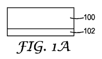
図1Aは、材料100の一部分の断面の概略立面図である。材料100は任意の好適な化合物又は物質であってよい。実施形態によっては、材料100の1つ以上の部分が多光子反応を受けることができる場合がある。「多光子反応を受けることができる」という表現は、その材料が同時に複数の光子を吸収することにより多光子反応を受けることができることを意味すると理解されるべきである。例えば、材料100は、2つの光子を同時に吸収することによって2光子反応を受けることが可能である。多光子反応を受けることができる好適な材料及び材料系は、例えば、米国特許第7,583,444号(DeVoeら)、米国特許第7,941,013号(Marttilaら)、及び国際特許公開第WO2009/048705 A1号(「Highly Functional Multiphoton Curable Reactive Species」と題する)に説明されている。
FIG. 1A is a schematic elevational view of a cross section of a portion of
場合によっては、材料100は、酸又はラジカル開始化学反応を受けることが可能な少なくとも1つの反応種と、少なくとも1つの多光子光開始剤系と、を含む、光反応性組成物であってもよい。光反応組成物で使用するのに好適な反応種としては、硬化性及び非硬化性の化学種の両方が挙げられる。例示的な硬化性の化学種には、付加重合性モノマー及びオリゴマー、並びに付加架橋性ポリマー(例えば、アクリレート、メタクリレート、ポリ(メチルメタクリレート)、及びスチレンなどの特定のビニル化合物を含む、フリーラジカル重合性又は架橋性のエチレン不飽和性の化学種)、更には、カチオン重合性モノマー及びオリゴマー、並びにカチオン架橋性ポリマー(それらは最も一般的には酸開始されており、例えばエポキシ、ビニルエーテル、シアネートエステルなどが含まれる)、その他同種のもの、並びにそれらの混合物が挙げられる。例示的な非硬化性の化学種には、酸又はラジカル誘起反応の際に溶解度が増大し得る反応性ポリマーが挙げられる。そのような反応性ポリマーには、例えば、光生成した酸によって可溶性の酸基へと変換され得るエステル基を持つ非水溶性ポリマー(例えば、ポリ(4−t−ブトキシカルボニルオキシスチレン))が挙げられる。また、非硬化性の化学種には化学増幅フォトレジストが挙げられる。
In some cases,
多光子光開始剤系により、第1の材料を露光させるために用いる光の集束ビームの焦点領域に重合化を制限又は限定することが可能となる。このような系は、好ましくは、少なくとも1つの多光子光増感剤、少なくとも1つの光開始剤(又は電子受容体)、及び場合によっては、少なくとも1つの電子供与体を含む2成分又は3成分系である。 The multi-photon photoinitiator system makes it possible to limit or limit the polymerization to the focal region of the focused beam of light used to expose the first material. Such a system is preferably a two or three component comprising at least one multiphoton photosensitizer, at least one photoinitiator (or electron acceptor) and optionally at least one electron donor. It is a system.
材料100は、基材102上に位置づけられ得る。材料100は、その特定の用途に好適な任意のコーティング法により基材102にコーティングすることができる。例えば、材料100はフラッドコーティングにより基材102にコーティングすることができる。他の例示的な方法には、ナイフコーティング、ノッチコーティング、リバースロールコーティング、グラビアコーティング、スプレーコーティング、バーコーティング、スピンコーティング、及びディップコーティングが挙げられる。
The
基材102は、種々様々なフィルム、シート、及びその他の表面材(シリコンウェハ及びガラスプレートを含む)から、特定の用途及び用いる露光方法に応じて選定され得る。場合によっては、基材102は、材料100が均一な厚さを有するように十分に平坦である。場合によっては、材料100は大きい塊の形態で露光されてもよい。そのような場合、基材102は製作プロセスから除外されてもよい。プロセスが1つ以上の電鋳工程を含む場合などでは、基材102は導電性又は半導電性であってよい。
The
次に、材料100は、露光領域内の第1の材料による多光子の同時吸収を生じさせるのに十分な強度を有する入射光に、選択的に露光される。この露光は、十分な強度の光を供給することが可能な任意の方法で達成させることができる。代表的な露光法は、同一出願人が所有する、2007年3月23日出願の「Process For Making Microneedles,Microneedle Arrays,Masters,And Replication Tools」と題する、同一出願人による米国特許出願公開第2009/0099537号に記載されている。
Next, the
材料100を選択的に露光した後、露光した材料100を溶媒に入れて、溶媒への溶解度がより高い領域を溶解する。露光した第1の材料を現像するために使用され得る代表的な溶媒には、水(例えば、1〜12の範囲のpHを有する)及び水と有機溶媒との混和性配合物(例えば、メタノール、エタノール、プロパノール、アセトン、アセトニトリル、ジメチルホルムアミド、N−メチルピロリドンなど、及びそれらの混合物)などの水性溶媒、並びに有機溶媒が挙げられる。代表的な有用な有機溶媒としては、アルコール類(例えば、メタノール、エタノール、及びプロパノール)、ケトン類(例えば、アセトン、シクロペンタノン、及びメチルエチルケトン)、芳香族化合物類(例えば、トルエン)、ハロカーボン類(例えば、塩化メチレン、及びクロロホルム)、ニトリル類(例えば、アセトニトリル)、エステル類(例えば、ジエチルエーテル、及びテトラヒドロフラン)、アミド類(例えば、N−メチルピロリドン)など、及びこれらの混合物が挙げられる。
After the
図1Bは、露光及び溶解後の材料100に相当する多光子マスター110の断面概略立面図である。多光子マスター110は、少なくとも1つの第1の微細構造114を含む第1の微細構造化パターン114を含む。多光子マスター110の全体の寸法及び厚さに対する第1の微細構造114の寸法は、必ずしも縮尺通りではなく、例示を容易にするために割合で図1Bで示されている。第1の微細構造化パターン112は、任意のピッチ、形状及び寸法を含む任意の好適な微細構造の構成を有し得る。実施形態によっては、微細構造114は三次元直線形を有してもよく、又はそれらは三次元曲線形を有してもよい。各微細構造114は同じでもよく、あるいは、それらはランダム若しくは擬似ランダムに変えられてもよく、又は1つ以上の軸に沿った勾配で変えられてもよい。図1A〜1Jに示されるように、仕上がったノズルの最終的な形状の一部にとって微細構造114は重要であるので、多光子マスター110の形成は精密な制御を必要とし得る。
FIG. 1B is a cross-sectional schematic elevation view of a
実施形態によっては、図1A〜1Jには示されていないが、多光子マスター110は、薄い導電性のシード層で第1の微細構造化パターン114の上面をコーティングすることにより、金属塗装される、ないしは別の方法で導電性に作られる。導電性シード層は、例えば、銀、クロム、金、チタン等の任意の導電材を含むことができる。場合によっては、シード層は、約50nm未満、又は約40nm未満、又は約30nm未満、又は約20nm未満の厚さを有することができる。
In some embodiments, although not shown in FIGS. 1A-1J, the
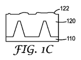
次に、シード層を用いて、多光子マスター110、より具体的には第1の微細構造化パターン112を電鋳して、図1Cに示すように、多光子マスター110の上に堆積材料120を形成する。電鋳には、電鋳溶液の組成、電流密度、メッキ時間、及び基材速度などの、任意の好適なプロセス変数を用いることができる。実施形態によっては、電鋳溶液は、例えば、硫化ヒドロカルビル化合物、アリルスルホン酸、種々のポリエチレングリコール、及びバイチオカルバメート又はチオ尿素を含むチオカルバメート、並びにそれらの誘導体等、有機レベラーを含有してもよい。堆積材料120は、銀、不動態化銀、金、ロジウム、アルミニウム、高反射率アルミニウム、銅、コバルト、インジウム、ニッケル、クロム、錫、並びにこれらの合金及びこれらの組合せなどの任意の好適な材料でよい。堆積材料120は、一般には材料100と異なる材料である。
Next, using the seed layer, the
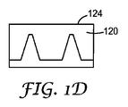
電鋳処理の結果、堆積材料120の片面に粗い又は均一ではない電鋳表面122を得る場合がある。所望により、電鋳した表面122を研削又は研磨して、図1Dに示すような平滑な表面124の堆積材料120を得てもよい。好適な研削方法には、表面研削及びメカニカルミリングを挙げることができる。
The electroforming process may result in a rough or non-uniform
実施形態によっては、シード層で第1の微細構造化パターン112を最初にコーティングせずに、堆積材料120を多光子マスター110に直接に堆積してもよい。この工程を排除する好適なプロセスとしては、例えば、スパッタリング及び化学蒸着が挙げられる。換言すれば、堆積材料120は電鋳されなくてもよい。
In some embodiments, the
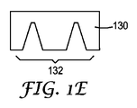
図1Eは、多光子マスター110から取り除かれた又は取り外された鋳型130(図1Dの堆積材料120に本質的に相当する)を示す。鋳型130の取り除き又は取り外しは、実施形態によっては手作業で行うことができる。用途によっては、鋳型130が多光子マスター110から取り除かれた後に、代わりに研削又は研磨工程(図では、図1Cと図1Dとの間で行われる)を行うことが望ましい場合がある。多光子マスター110は、第2の微細構造化パターン132を形成する鋳型130に刻み込みを入れる。第2の微細構造化パターンは、第1の微細構造化パターン112の陰複製におおむね対応する。実施形態によっては、鋳型130が電鋳処理により形成されるので、鋳型130は、使用した金属の耐久性及び耐磨耗性を引き継いだ望ましい物理的特性を有することができる。
FIG. 1E shows a mold 130 (essentially corresponding to the deposited
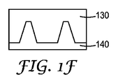
図1Fは、下プレート140の形成に使用される鋳型130を示す。下プレート140は、金属、セラミック、又は高分子の基材などの任意の好適な材料で形成されてよく、後の処理工程中に耐えかつ形状を維持するように、耐久性及び高い融点又はガラス転移温度といった物理的特性を得るように選択することができる。下プレートの材料は、材料100及び堆積材料120の両方と異なっていてよい。他の実施形態では、下プレートの材料は堆積材料120と同じであってよい。
FIG. 1F shows the
下プレート140は、例えば鋳造及び硬化法又は射出成形といった任意の好適な方法により鋳型130のパターン化された表面(図1Eの第2の微細構造化パターン132に対応する)とぴったり一致するようにインプリント法ないしは別の方法で刻まれる。実施形態によっては、鋳型130は、放電加工(EDM)により下プレート140に第2の微細構造化パターン132を複製するために工具又は電極として機能することができる。鋳型130を複数回使用して、例えば、下プレート140を鋳型130の2倍の長さにしたい場合は、鋳型130を2回使用して、2つの隣接した微細構造化パターンを形成することができ、更にそれを繰り返すことにより、下プレート140全体を形成することができる。同様に、下プレート140の一部分にパターンを形成するためだけに鋳型130を使用してもよく、換言すると、用途によっては、下プレート140の全体に満たない部分に微細構造化パターンを形成することが望ましい場合がある。
The
図1Gは、鋳型130から取り除かれた、ないしは別の方法で取り外された後の下プレート140を示す。下プレートは、第1の微細構造化パターン112と実質的に同じであり実質的に第2の微細構造化パターン132のネガティブであるべきである第3の微細構造化パターン142を含む。第3の微細構造化パターン142は、図1Bの多光子マスター110に生成された第1の微細構造化パターン112の微細構造114と実質的に同じであり得るピーク144を1つ以上含む。実際には、製造プロセスによって微細構造114とピーク144との間にわずかな変化が導入されてもよい。
FIG. 1G shows the
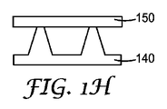
図1Hは、下プレート140及び上プレート150を示す。上プレート150は、任意の好適な材料であってよく、任意の好適な形状又はサイズであってよい。実施形態によっては、上プレート150は下プレート140と同じ材料であってよい。上プレート150もまた、例えば鋼など金属又は金属合金で形成され得る。実施形態によっては、プレートが繰り返しの使用に対して耐摩耗性及び耐久性を有するように上プレート150の寸法が選択されてもよい。上プレート150は、下プレート140のピークに近接して位置づけられることができ、実施形態によってはそれら2つのプレートは接触している場合がある。実施形態によっては、上プレート150は、形状化、構造化、又は微細パターン化された表面を有し得る。下プレート140を鋳型インサートと呼ぶ場合がある。
FIG. 1H shows the
図1Iは、射出成形工程を示す。射出された材料160は、下プレート140と上プレート150との間の空洞を充填する。図1Iの二次元表現が図解の簡易さを目的としており、下プレート140と上プレート150との間の区域が三次元の体積を表現し得ることは、当業者には明白であろう。言い換えれば、下プレート140のピークとピークとの間の中間空洞が単離されているように見えても、二次元では見えないチャネルが存在し得、単離しているかのように見える空間を射出された材料160が満たすことが可能である。
FIG. 1I shows the injection molding process. The injected
図1Iは、あくまで射出成形工程を表現する概略図であり、適切な流れ特性を樹脂から得るために必要な、例えば、側壁、射出ゲート、適した入力ライン、及び加熱要素といった、このプロセスに必要な他の構成要素が含まれ得る。射出された材料160は、射出された材料160が十分に剛性の部品を形成する温度以下に維持され得る、下プレート140と上プレート150との間に形成された空洞内に流れ込む。圧力を慎重に制御することは、プレート間の容積を完全に満たすための射出成形プロセスの好適なパラメータである。
FIG. 1I is a schematic representation of the injection molding process only and is necessary for this process, such as sidewalls, injection gates, suitable input lines, and heating elements necessary to obtain the proper flow characteristics from the resin. Other components may be included. The injected
射出された材料160は任意の材料でよく、材料の射出とともに使用されるプロセスによって異なり得る。例えば、射出成形工程は、ポリマー射出成形であり得る。したがって、射出材料160は、部分的に又は完全にポリマー、高分子樹脂、又はフッ素化ポリマーであり得る。材料は、ガラス転移温度及び融点などの、そのレオロジー特性のために選定することができる。
The injected
実施形態によっては、射出成形工程は、金属射出成形(MIM)のような粉末射出成形工程を含むことがある。このプロセスでは、射出材料160は金属粉末及びバインダーの両方の化合物であり得、いくつかの高分子物質を含み得る。金属粉末及びバインダーを均質化し、次いで加熱し、標準的なポリマー射出成形で行われるようにダイ又は鋳型の中に射出し、その化合物を冷却して望みの形状にする。これで、いわゆる「グリーン」部品が作られる。バインダーは射出成形工程には必要であるが、成形後の完成部品には望ましくない場合がある。その場合は、熱劣化によりバインダーを除去するために、特定の慎重に制御された温度プロファイルにしたがって、成形されたグリーン部品を加熱するデボンディング工程が必要である。実施形態によっては、デボンディングは、有機溶媒でバインダーを溶解することにより行われてもよいし、又は触媒含有雰囲気を提供することにより行われてもよい。バインダーを除去した後、部品を焼結する。焼結工程では、原子の拡散により成形部品の密度を増大させるために、金属の融点未満ではあるが加熱する必要がある。場合によっては、焼結は、理論上の最大密度の90%、95%、97%、又は99%を超える密度を達成することができる。
In some embodiments, the injection molding process may include a powder injection molding process such as metal injection molding (MIM). In this process, the
実施形態によっては、射出成形工程は、微細金属射出成形(μMIM)を含む場合がある。微細金属射出成形は従来の金属射出成形と概ね同様であるが、特徴の寸法がより小さい(一般には数十ミクロン又は数百ミクロン単位)ために、鋳型形成プロセスのより精密な制御とともに、より小さい粒径の金属粉末が必要とされる。本明細書に記載した、精密な特徴の制御による鋳型形成のためのいくつかの技法は、例えば、多光子露光プロセスのような微細金属成形射出プロセスとともに有利に使用されることができる。これと関連した技法である微細セラミック射出成形(μCIM)(金属粉末の代わりにセラミック粉末を使用する)は、特に、より小さい粉末粒径を実現できるので、用途によっては有利であり得る。粉末の粒径が小さいと、忠実度の高い非常に精緻な特徴を再製する能力を高めることができる。μMIM及びμCIMの一般的名称は、微粉末射出成形(μPIM)である。 In some embodiments, the injection molding process may include fine metal injection molding (μMIM). Fine metal injection molding is generally similar to conventional metal injection molding, but is smaller with more precise control of the mold forming process due to the smaller feature dimensions (typically in the order of tens or hundreds of microns). A metal powder with a particle size is required. Several techniques described herein for mold formation with precise feature control can be advantageously used with fine metal forming injection processes such as, for example, a multi-photon exposure process. A related technique, fine ceramic injection molding (μCIM), which uses ceramic powder instead of metal powder, can be advantageous depending on the application, especially since smaller powder particle sizes can be achieved. The small particle size of the powder can increase the ability to recreate very precise features with high fidelity. The common name for μMIM and μCIM is fine powder injection molding (μPIM).
射出材料160は、下プレートの材料と同じ又は類似のものでよい。しかしながら、実施形態によっては、射出材料160は、材料100、堆積材料120、及び下プレート140の材料と異なる材料である。
The
完成部品を図1Jに示す。下プレート140及び上プレート150の形状のために、ノズルアレイ170は1つ以上の貫通穴172を含んでよい。図1Jもまた、三次元部品の二次元断面図であり、図でノズルアレイ170が3つの部品であるように見えていても、他の断面ではアレイはおそらく結合されている。貫通穴172は、多光子マスター110の第1の微細構造化パターン112を含む、プロセスのどこかで使用される微細構造化パターンと関係しているので、貫通穴172の形状及び輪郭の正確な制御は、各微細構造114の正確な制御により達成され得る。実施形態によっては、例えば貫通穴172を開くために裏面研削又はEDMを行う、又は化学抵抗性、耐摩擦性、若しくは付着汚れ防止といった望ましい特性を組み込むために任意の好適なプロセスによってノズルアレイ170の表面を金属で被覆若しくは塗装するなど、形成後の処理が望ましい場合がある。
The completed part is shown in FIG. 1J. Due to the shape of the
注目すべきこととして、射出成形工程を迅速に、かつ高い信頼性で繰り返すことができ、高容量の工程(すなわち、各部品に行う必要のある工程)を、より時間のかからない作業と調整することができるので、部品を高容量で製造することが問題とならない。更に、本明細書に記載の方法は、各部品につきいくつかの工程が行われなければならない従来のプロセスと異なり、1つの高容量工程のみを含む場合がある。この記載の方法の効率は、従来のプロセスよりも時間及び費用を節約することができる。例えば、各部品を電鋳するのでなく、電鋳工程を1回行うだけで多くの部品を得ることが可能であり、高容量、時間、及びコストの節約がもたらされる。同様に、実施形態によっては、各部品を研削する必要のある従来のプロセスと異なり、射出成形された部品を更に研削して貫通穴を開ける必要がない。 It should be noted that the injection molding process can be repeated quickly and reliably, coordinating high capacity processes (ie processes that need to be performed on each part) with less time consuming work. Therefore, it is not a problem to manufacture parts with high capacity. Further, the methods described herein may include only one high capacity step, unlike conventional processes where several steps must be performed for each part. The efficiency of the described method can save time and money over conventional processes. For example, rather than electroforming each part, it is possible to obtain many parts with only one electroforming process, resulting in high capacity, time and cost savings. Similarly, in some embodiments, unlike conventional processes where each part needs to be ground, there is no need to further grind the injection molded part to drill through holes.
図2A〜2Hは、別のノズル製造方法の中間体の概略断面立面図である。冗長を避けるため、図1A〜1Jに関しての説明を図2A〜2Hに関して繰り返さないが、それらに対応する説明は、対応する工程に適用するものと想定することができる。図2Aは図1Aに対応し、それには材料200(図1Aの材料100に当たる)及び基材202(図1Aの基材102に対応する)が含まれる。材料及び基材は、前述の方法と同じく、多光子反応を受けることができる材料を含む任意の材料を含むことができる。
2A to 2H are schematic cross-sectional elevation views of an intermediate body of another nozzle manufacturing method. To avoid redundancy, the description with respect to FIGS. 1A-1J will not be repeated with respect to FIGS. 2A-2H, but the corresponding description may be assumed to apply to the corresponding process. FIG. 2A corresponds to FIG. 1A, which includes material 200 (corresponding to
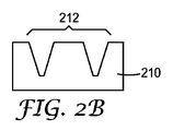
材料200を好適な放射線に選択的に露光して溶解した後、図2Bに示すように、微細構造化パターン212を含む多光子マスター210が生成される。第1の微細構造化パターン212は本質的に図1Bの第1の微細構造化パターン112のネガティブであることに注意されたい。
After the
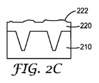
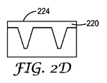
次いで、多光子マスター210をシードし、堆積材料220で電鋳すると、図2Cに示すように粗い表面222が形成され得る。堆積材料220は、図1Cに関して上述したプロセス条件を含む任意のプロセス条件下で適用される任意の材料でよい。粗い表面222を研削又は研磨して、図2Dに示すように堆積材料220の平滑な表面224を形成することができる。
The
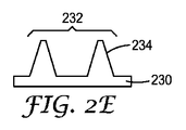
図2Eは、下プレート230を示す(多光子マスター210から取り外された図2Dの平滑な表面224を有する堆積材料220に本質的に対応する)。下プレート230は、第1の微細構造化パターン212の実質的にネガティブである第2の微細構造化パターン232を含む。第2の微細構造化パターン232は微細構造234を含む。図2A〜2Hに図示するネガティブプロセス(最初の多光子マスターは完成プレートのネガティブであるので、このように呼ぶ)は堆積材料から下プレートを生成し、一方、図1A〜1Jに図示するポジティブプロセス(最初の多光子マスターは実質的に完成プレートと同じであるので、このように呼ぶ)は中間体鋳型を用いて下プレートを生成することに注意されたい。関係する用途及び製造プロセスに依存して、各アプローチが有利であり得る。
FIG. 2E shows the lower plate 230 (corresponding essentially to the deposited
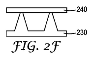
図2Fは、下プレート230のピークに近接して位置づけられた上プレート240を示す。上プレートもまた、任意の好適な材料(鋼が挙げられる)でよく、任意の好適な大きさ又は寸法でよい。上及び下という用語は、本明細書では例示及び説明の便宜上使用されており、2つのプレートの特徴を限定する意味はなく、それらのプレートは用途に応じて異なる配向で置かれ得る。
FIG. 2F shows the upper plate 240 positioned close to the peak of the
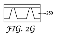
図2Gが図示する射出成形工程は、図1Iに対応する記述で説明されている工程と同じであってもよいし異なっていてもよい。前述の方法に関しては、射出材料250は、任意の好適なポリマー、金属粉末、セラミック、又はそれらのブレンドを含んでよく、その射出成形工程には、従来の射出成形又は粉末射出成形、例えば金属射出成形、微細金属射出成形若しくは微細セラミック射出成形が含まれ得る。
The injection molding process illustrated in FIG. 2G may be the same as or different from the process described in the description corresponding to FIG. 1I. With respect to the foregoing method, the
完成したノズルアレイ260が図2Hに示されており、貫通穴262を含んでいる。ノズルアレイ260は、図1Jのノズルアレイ170に対応するものであり、いずれの方法でも同一の、実質的に同一の、又は少なくとも類似の部品が製造され得ることを示している。
A completed
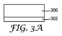
図3A〜3Eは、燃料噴射ノズルの更に別の作製方法の中間体の概略断面図を示す。図2A〜2Hの場合と同じく、既に説明した類似した処理工程の詳細な説明を全て繰り返すことはしないが、特に記載がない限り、それらの説明が適用することを想定することができる。 3A to 3E are schematic cross-sectional views of an intermediate body of still another method for manufacturing a fuel injection nozzle. As in the case of FIGS. 2A to 2H, the detailed description of similar processing steps already described will not be repeated, but it can be assumed that these descriptions apply unless otherwise specified.
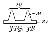
図3Aは、基材302の上に位置づけられた材料300の一部分を示す。材料300は、任意の好適な材料又は材料の組み合わせであり得る。しかしながら、材料300は、多光子反応を受けられる能力のために選択されるのではなく、したがって、選択的に露光されない。その代わりに、材料300は、射出成形ダイの下プレートとしての使用に好適であり得る物質であるべきである。図3Aと3Bとの間で、材料300は、例えば末端ミリング、EDM、研削、エンボス等のような従来法のいずれかで形状化又は形成されて、図3Bに示すような下プレート310をもたらすことができる。実施形態によっては、下プレート310は、3D印刷のようなプロセスから直接に生成することができ、その場合、材料層が堆積されて所望の部品を形成する。
FIG. 3A shows a portion of
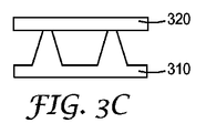
下プレート310は、微細構造314を含む微細構造化パターン312を片面上に有する。微細構造のこのパターン及び一式は、任意の好適な大きさ、形状、及びピッチ又は構成であり得る。図3Cは、上プレート314が下プレートのピークに近接して置かれた下プレート310を示す。
The
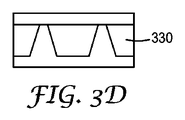
図3Dは、図2G又は図1Iのいずれかに対応する記述で説明されたのと同じ又は類似の工程であり得る射出成形工程を示す。それらの場合と同じく、この射出成形工程には、従来のポリマー射出成形、粉末射出成形、又は微細金属射出成形及び微細セラミック射出成形などの微細粉末射出成形が含まれ得る。 FIG. 3D illustrates an injection molding process that may be the same or similar process described in the description corresponding to either FIG. 2G or FIG. 1I. As in those cases, the injection molding process may include conventional polymer injection molding, powder injection molding, or fine powder injection molding such as fine metal injection molding and fine ceramic injection molding.
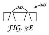
図3Eは、射出成形ダイから取り外された後の完成部品を示す。ノズルアレイ340は、燃料噴霧を適切に方向付け制御するために任意の好適な外形を有し得る貫通穴342を含む。ノズルアレイ340は、図2Hのノズルアレイ260及び図1Jのノズルアレイ170の両方に対応するものであり、この方法は、本明細書に記載の他の2つの一般的方法と実質的に同じ完成部品をもたらすことができることを実証している。
FIG. 3E shows the finished part after it has been removed from the injection die. The
様々な代表的実施形態
1.
多光子反応を受けることができる第1の材料を準備する工程、
多光子プロセスを用いて前記第1の材料に第1の微細構造化パターンを形成する工程、
前記第1の微細構造化パターンを前記第1の材料と異なる第2の材料に複製して、第2の材料の第2の微細構造化パターンを含む第1の鋳型を作製する工程、
前記第2の微細構造化パターンを第3の材料に複製して、前記第3の材料に複数の微細構造を含む第3の微細構造化パターンを含む第2の鋳型を作製する工程、
前記第3の材料の複数の微細構造のピークに近接して前記第2の鋳型の上にプレートを位置づける工程、
前記第3の微細構造化パターンの周囲の前記第2の鋳型の上、かつ前記プレートの下の区域に、第4の材料を射出成形する工程、及び
前記プレート及び第2の鋳型を取り除いて、前記第4の材料を含み、かつ複数の貫通穴を更に備える、燃料噴射ノズルを得る工程、を含む、燃料噴射ノズルを製造する方法。
2.前記第3の材料が前記第1及び第2の材料と異なる、実施形態1に記載の方法。
3.前記第3の材料が前記第2の材料と同じ材料である、実施形態1に記載の方法。
4.前記第4の材料が前記第3の材料と同じ材料である、実施形態1に記載の方法。
5.前記第4の材料が前記第1、第2及び第3の材料と異なる、実施形態1に記載の方法。
6.第2の材料に前記第1の微細構造化パターンを複製する工程が、前記第1の微細構造化パターンを電鋳する工程を含む、実施形態1〜5のいずれか一項に記載の方法。
7.前記第2の材料がニッケル又はニッケル合金を含む、実施形態6に記載の方法。
8.前記第4の材料がポリマーを含む、実施形態1〜7のいずれか一項に記載の方法。
9.前記第4の材料が金属を含む、実施形態1〜7のいずれか一項に記載の方法。
10.前記第4の材料がセラミックを含む、実施形態1〜7のいずれか一項に記載の方法。
11.前記第1の材料がポリ(メチルメタクリレート)を含む、実施形態1〜10のいずれか一項に記載の方法。
12.前記第1の材料が2光子反応を受けることができる、実施形態1〜10のいずれか一項に記載の方法。
13.前記2光子反応が、同時に2つの光子を吸収することを含む、実施形態12に記載の方法。
14.前記微細構造が三次元直線体を含む、実施形態1〜13のいずれか一項に記載の方法。
15.前記微細構造が三次元曲線体を含む、実施形態1〜13のいずれか一項に記載の方法。
16.前記複数の貫通穴を開けるために、前記燃料噴射ノズルの残っている前記第4の材料の部分を取り除く工程を更に含む、実施形態1〜15のいずれか一項に記載の方法。
17.前記残っている部分を取り除く工程が裏面研削により行われる、実施形態16に記載の方法。
18.前記残っている部分を取り除く工程がEDMにより行われる、実施形態16に記載の方法。
19.前記燃料噴射ノズルのデボンディングを更に含む、実施形態1〜18のいずれか一項に記載の方法。
20.前記燃料噴射ノズルの焼結を更に含む、実施形態1〜19のいずれか一項に記載の方法。
21.前記燃料噴射ノズルの表面への金属の適用を更に含む、実施形態1〜20のいずれか一項に記載の方法。
22.
多光子反応を受けることができる第1の材料を準備する工程、
多光子プロセスを用いて前記第1の材料に第1の微細構造化パターンを形成する工程、
前記第1の微細構造化パターンを前記第1の材料と異なる第2の材料に複製して、前記第2の材料の複数の微細構造を含む第2の微細構造化パターンを含む鋳型を作製する工程、
前記第2の材料の複数の微細構造のピークに近接して前記鋳型の上にプレートを位置づける工程、
前記第2の微細構造化パターンの周囲の前記鋳型の上、かつ前記プレートの下の区域に、第3の材料を射出成形する工程、及び
前記プレート及び鋳型を取り除いて、前記第3の材料を含み、かつ複数の貫通穴を更に備える、燃料噴射ノズルを得る工程、を含む、燃料噴射ノズルを製造する方法。
23.前記第3の材料が前記第1及び第2の材料と異なる、実施形態22に記載の方法。
24.前記第3の材料が前記第2の材料と同じ材料である、実施形態22に記載の方法。
25.前記複数の貫通穴を開けるために、前記燃料噴射ノズルの残っている前記第3の材料の部分を取り除く工程を更に含む、実施形態22に記載の方法。
26.前記残っている部分を取り除く工程が裏面研削により行われる、実施形態25に記載の方法。
27.前記残っている部分を取り除く工程がEDMにより行われる、実施形態25に記載の方法。
28.前記燃料噴射ノズルのデボンディングを更に含む、実施形態22〜27のいずれか一項に記載の方法。
29.前記燃料噴射ノズルの焼結を更に含む、実施形態22〜28のいずれか一項に記載の方法。
30.前記燃料噴射ノズルの表面への金属の適用を更に含む、実施形態22〜29のいずれか一項に記載の方法。
31.燃料噴射ノズルの製造方法であって、
第1の材料に微細構造化パターンを生成することにより鋳型を形成する工程であって、前記第1の微細構造化パターンが複数の微細構造を含んでいる、工程、
前記第1の材料の複数の微細構造のピークに近接して前記鋳型の上にプレートを位置づける工程、
前記微細構造化パターンの周囲の前記鋳型の上かつ前記プレートの下の区域に、前記第1の材料と異なる第2の材料を射出成形する工程、及び
前記プレート及び鋳型を取り除いて、前記第2の材料を含み、かつ複数の貫通穴を更に備える、燃料噴射ノズルを得る工程、を含む、方法。
32.微細構造化パターンを生成する工程が末端ミリングにより行われる、実施形態31に記載の方法。
33.微細構造化パターンを生成する工程が研削により行われる、実施形態31又は32のいずれか一項に記載の方法。
34.微細構造化パターンを生成する工程がEDMによって行われる、実施形態31〜33のいずれか一項に記載の方法。
35.前記複数の貫通穴を開けるために、前記燃料噴射ノズルの前記第2の材料の残っている部分を取り除く工程を更に含む、実施形態31〜34のいずれか一項に記載の方法。
36.前記残っている部分を取り除く工程が裏面研削により行われる、実施形態35に記載の方法。
37.前記残っている部分を取り除く工程がEDMにより行われる、実施形態35に記載の方法。
38.前記燃料噴射ノズルのデボンディングを更に含む、実施形態31〜37のいずれか一項に記載の方法。
39.前記燃料噴射ノズルの焼結を更に含む、実施形態31〜38のいずれか一項に記載の方法。
40.前記燃料噴射ノズルの表面への金属の適用を更に含む、実施形態31〜39のいずれか一項に記載の方法。
41.
多光子反応を受けることができる第1の材料を準備する工程、
多光子プロセスを用いて前記第1の材料に第1の微細構造化パターンを形成する工程、
前記第1の微細構造化パターンを前記第1の材料と異なる第2の材料に複製して、前記第2の材料の第2の微細構造化パターンを含む第1の工具を作製する工程、
前記工具を用いて、前記第2の微細構造化パターンの反転である複数の微細構造を含む第3の微細構造化パターンを金属基材に形成して鋳型を作る工程、
前記金属基材の複数の微細構造のピークに近接して前記第2の鋳型の上にプレートを位置づける工程、
前記第3の微細構造化パターンの周囲の前記鋳型の上、かつ前記プレートの下の区域に、第3の材料を射出成形する工程、及び
前記プレート及び鋳型を取り除いて、前記第3の材料を含み、かつ複数の貫通穴を更に備える、燃料噴射ノズルを得る工程、を含む、燃料噴射ノズルを製造する方法。
42.前記工具が電極である、実施形態41に記載の方法。
43.前記工具が、EDMにより金属基材に第3の微細構造化パターンを形成する、実施形態41又は42に記載の方法。
44.前記複数の貫通穴を開けるために、前記燃料噴射ノズルの残っている前記第3の材料の部分を取り除く工程を更に含む、実施形態41〜43のいずれか一項に記載の方法。
45.前記残っている部分を取り除く工程が裏面研削により行われる、実施形態44に記載の方法。
46.前記残っている部分を取り除く工程がEDMにより行われる、実施形態44に記載の方法。
47.前記燃料噴射ノズルのデボンディングを更に含む、実施形態41〜46のいずれか一項に記載の方法。
48.前記燃料噴射ノズルの焼結を更に含む、実施形態41〜47のいずれか一項に記載の方法。
49.前記燃料噴射ノズルの表面への金属の適用を更に含む、実施形態41〜48のいずれか一項に記載の方法。
Various exemplary embodiments
Providing a first material capable of undergoing a multiphoton reaction;
Forming a first microstructured pattern in the first material using a multiphoton process;
Replicating the first microstructured pattern onto a second material different from the first material to produce a first mold comprising a second microstructured pattern of a second material;
Replicating the second microstructured pattern onto a third material to produce a second template including a third microstructured pattern including a plurality of microstructures in the third material;
Positioning a plate on the second mold proximate to a plurality of microstructure peaks of the third material;
Injection molding a fourth material onto the second mold around the third microstructured pattern and below the plate; and removing the plate and the second mold; A method of manufacturing a fuel injection nozzle, comprising: obtaining a fuel injection nozzle comprising the fourth material and further comprising a plurality of through holes.
2. The method of embodiment 1, wherein the third material is different from the first and second materials.
3. The method of embodiment 1, wherein the third material is the same material as the second material.
4). The method of embodiment 1, wherein the fourth material is the same material as the third material.
5). The method of embodiment 1, wherein the fourth material is different from the first, second and third materials.
6). Embodiment 6. The method according to any one of embodiments 1-5, wherein the step of replicating the first microstructured pattern on a second material includes the step of electroforming the first microstructured pattern.
7). The method of embodiment 6, wherein the second material comprises nickel or a nickel alloy.
8). Embodiment 8. The method of any one of embodiments 1-7, wherein the fourth material comprises a polymer.
9. Embodiment 8. The method according to any one of embodiments 1-7, wherein the fourth material comprises a metal.
10. Embodiment 8. The method of any one of embodiments 1-7, wherein the fourth material comprises a ceramic.
11. Embodiment 11. The method of any one of embodiments 1-10, wherein the first material comprises poly (methyl methacrylate).
12 The method of any one of embodiments 1-10, wherein the first material is capable of undergoing a two-photon reaction.
13. The method of embodiment 12, wherein the two-photon reaction comprises simultaneously absorbing two photons.
14 The method according to any one of embodiments 1-13, wherein the microstructure comprises a three-dimensional linear body.
15. The method according to any one of embodiments 1-13, wherein the microstructure comprises a three-dimensional curved body.
16. 16. The method of any one of embodiments 1-15, further comprising removing the remaining portion of the fourth material of the fuel injection nozzle to open the plurality of through holes.
17. The method of embodiment 16 wherein the step of removing the remaining portion is performed by backside grinding.
18. Embodiment 17. The method of embodiment 16 wherein the step of removing the remaining portion is performed by EDM.
19. The method of any one of embodiments 1-18, further comprising debonding of the fuel injection nozzle.
20. The method of any one of embodiments 1-19, further comprising sintering the fuel injection nozzle.
21. Embodiment 21. The method of any one of embodiments 1-20, further comprising applying a metal to a surface of the fuel injection nozzle.
22.
Providing a first material capable of undergoing a multiphoton reaction;
Forming a first microstructured pattern in the first material using a multiphoton process;
The first microstructured pattern is duplicated on a second material different from the first material to produce a template including a second microstructured pattern including a plurality of microstructures of the second material. Process,
Positioning a plate on the mold proximate to a plurality of microstructure peaks of the second material;
Injection molding a third material into the area around the second microstructured pattern above the mold and below the plate; and removing the plate and mold to form the third material A method of manufacturing a fuel injection nozzle, comprising: obtaining a fuel injection nozzle, further comprising a plurality of through holes.
23. 23. The method of embodiment 22, wherein the third material is different from the first and second materials.
24. Embodiment 23. The method of embodiment 22 wherein the third material is the same material as the second material.
25. 23. The method of embodiment 22, further comprising removing the remaining portion of the third material of the fuel injection nozzle to open the plurality of through holes.
26. 26. The method of embodiment 25, wherein the step of removing the remaining portion is performed by backside grinding.
27. Embodiment 26. The method of embodiment 25, wherein the step of removing the remaining portion is performed by EDM.
28. Embodiment 28. The method of any one of embodiments 22 through 27, further comprising debonding the fuel injection nozzle.
29. Embodiment 29. The method of any one of embodiments 22 through 28, further comprising sintering the fuel injection nozzle.
30. 30. The method of any one of embodiments 22-29, further comprising applying a metal to a surface of the fuel injection nozzle.
31. A method for manufacturing a fuel injection nozzle, comprising:
Forming a template by generating a microstructured pattern in a first material, wherein the first microstructured pattern includes a plurality of microstructures;
Positioning a plate on the mold proximate to a plurality of microstructure peaks of the first material;
Injection molding a second material different from the first material in an area above the mold and under the plate around the microstructured pattern; and removing the plate and the mold; And obtaining a fuel injection nozzle, further comprising a plurality of through holes.
32. 32. The method of embodiment 31, wherein the step of generating the microstructured pattern is performed by end milling.
33. 33. A method according to any one of embodiments 31 or 32, wherein the step of generating the microstructured pattern is performed by grinding.
34. 34. The method of any one of embodiments 31-33, wherein the step of generating the microstructured pattern is performed by EDM.
35. 35. The method of any one of embodiments 31-34, further comprising removing a remaining portion of the second material of the fuel injection nozzle to form the plurality of through holes.
36. 36. The method of embodiment 35, wherein the step of removing the remaining portion is performed by back grinding.
37. 36. The method of embodiment 35, wherein the step of removing the remaining portion is performed by EDM.
38. 38. The method according to any one of embodiments 31-37, further comprising debonding the fuel injection nozzle.
39. 39. The method according to any one of embodiments 31-38, further comprising sintering the fuel injection nozzle.
40. The method of any one of embodiments 31-39, further comprising applying a metal to the surface of the fuel injection nozzle.
41.
Providing a first material capable of undergoing a multiphoton reaction;
Forming a first microstructured pattern in the first material using a multiphoton process;
Replicating the first microstructured pattern onto a second material different from the first material to produce a first tool including a second microstructured pattern of the second material;
Forming a third microstructured pattern on a metal substrate using the tool to form a third microstructured pattern including a plurality of microstructures that is a reversal of the second microstructured pattern;
Positioning a plate on the second mold proximate to a plurality of microstructure peaks of the metal substrate;
Injection molding a third material in an area above the mold and around the plate around the third microstructured pattern; and removing the plate and mold to form the third material A method of manufacturing a fuel injection nozzle, comprising: obtaining a fuel injection nozzle, further comprising a plurality of through holes.
42. 42. The method of embodiment 41, wherein the tool is an electrode.
43. 43. The method of embodiment 41 or 42, wherein the tool forms a third microstructured pattern on a metal substrate by EDM.
44. 44. The method according to any one of embodiments 41-43, further comprising removing the remaining portion of the third material of the fuel injection nozzle to open the plurality of through holes.
45. 45. The method of embodiment 44, wherein the step of removing the remaining portion is performed by back grinding.
46. 45. The method of embodiment 44, wherein the step of removing the remaining portion is performed by EDM.
47. 47. The method of any one of embodiments 41-46, further comprising debonding the fuel injection nozzle.
48. 48. The method according to any one of embodiments 41-47, further comprising sintering the fuel injection nozzle.
49. 49. The method according to any one of embodiments 41-48, further comprising applying a metal to the surface of the fuel injection nozzle.
本明細書に記載されている米国特許及び特許出願の全ては(本明細書で使用されるノズルの定義を明確にするために引用されている場合を除き)、あたかもそれらの全容が記載されているかのように、参照により組み込まれる。本発明は、先に記載された特定の実施例及び実施形態に限定されると考慮すべきではなく、このような実施形態は、本発明の様々な態様の説明を容易にするために詳細に記載される。むしろ、本発明は、添付の特許請求の範囲及びその等価物によって定義されるような本発明の範囲内に包含される様々な修正、同等のプロセス、及び代替的装置を含む、本発明のすべての態様を網羅するものと理解すべきである。 All of the U.S. patents and patent applications mentioned herein (except where cited to clarify the definition of nozzles used herein) are described in their entirety. Incorporated by reference as if. The present invention should not be considered limited to the particular examples and embodiments described above, but such embodiments are described in detail to facilitate the description of various aspects of the invention. be written. Rather, the invention includes all modifications, equivalent processes, and alternative devices encompassed within the scope of the invention as defined by the appended claims and their equivalents. It should be understood that this aspect is covered.
Claims (22)
多光子プロセスを用いて前記第1の材料に第1の微細構造化パターンを形成する工程、
前記第1の微細構造化パターンを前記第1の材料と異なる第2の材料に複製して、第2の材料の第2の微細構造化パターンを含む第1の鋳型を作製する工程、
前記第2の微細構造化パターンを第3の材料に複製して、前記第3の材料に複数の微細構造を含む第3の微細構造化パターンを含む第2の鋳型を作製する工程、
前記第3の材料の複数の微細構造のピークに近接して前記第2の鋳型の上にプレートを位置づける工程、
前記第3の微細構造化パターンの周囲の前記第2の鋳型の上、かつ前記プレートの下の区域に、第4の材料を射出成形する工程、並びに
前記プレート及び前記第2の鋳型を取り除いて、前記第4の材料を含み、かつ複数の貫通穴を更に備える、燃料噴射ノズルを得る工程、
を含む、燃料噴射ノズルを製造する方法。 Providing a first material capable of undergoing a multiphoton reaction;
Forming a first microstructured pattern in the first material using a multiphoton process;
Replicating the first microstructured pattern onto a second material different from the first material to produce a first mold comprising a second microstructured pattern of a second material;
Replicating the second microstructured pattern onto a third material to produce a second template including a third microstructured pattern including a plurality of microstructures in the third material;
Positioning a plate on the second mold proximate to a plurality of microstructure peaks of the third material;
Injection-molding a fourth material onto the second mold around the third microstructured pattern and below the plate; and removing the plate and the second mold Obtaining a fuel injection nozzle comprising the fourth material and further comprising a plurality of through holes;
A method for manufacturing a fuel injection nozzle.
多光子プロセスを用いて前記第1の材料に第1の微細構造化パターンを形成する工程、
前記第1の微細構造化パターンを前記第1の材料と異なる第2の材料に複製して、前記第2の材料の複数の微細構造を含む第2の微細構造化パターンを含む鋳型を作製する工程、
前記第2の材料の前記複数の微細構造のピークに近接して前記鋳型の上にプレートを位置づける工程、
前記第2の微細構造化パターンの周囲の前記鋳型の上、かつ前記プレートの下の区域に、第3の材料を射出成形する工程、並びに
前記プレート及び鋳型を取り除いて、前記第3の材料を含み、かつ複数の貫通穴を更に備える、燃料噴射ノズルを得る工程、を含む、燃料噴射ノズルを製造する方法。 Providing a first material capable of undergoing a multiphoton reaction;
Forming a first microstructured pattern in the first material using a multiphoton process;
The first microstructured pattern is duplicated on a second material different from the first material to produce a template including a second microstructured pattern including a plurality of microstructures of the second material. Process,
Positioning a plate on the mold proximate to the plurality of microstructure peaks of the second material;
Injection molding a third material in an area above the mold and around the plate around the second microstructured pattern; and removing the plate and mold to form the third material A method of manufacturing a fuel injection nozzle, comprising: obtaining a fuel injection nozzle, further comprising a plurality of through holes.
前記第1の材料の前記複数の微細構造のピークに近接して前記鋳型の上にプレートを位置づける工程、
前記微細構造化パターンの周囲の前記鋳型の上かつ前記プレートの下の区域に、前記第1の材料と異なる第2の材料を射出成形する工程、並びに
前記プレート及び鋳型を取り除いて、前記第2の材料を含み、かつ複数の貫通穴を更に備える、燃料噴射ノズルを得る工程、を含む、燃料噴射ノズルを製造する方法。 Forming a template by generating a microstructured pattern in a first material, wherein the first microstructured pattern includes a plurality of microstructures;
Positioning a plate on the mold proximate to the plurality of microstructure peaks of the first material;
Injection molding a second material different from the first material in a region around the mold and under the plate around the microstructured pattern; and removing the plate and the mold; A method of manufacturing a fuel injection nozzle, comprising: obtaining a fuel injection nozzle comprising the material of: and further comprising a plurality of through holes.
多光子プロセスを用いて前記第1の材料に第1の微細構造化パターンを形成する工程、
前記第1の微細構造化パターンを前記第1の材料と異なる第2の材料に複製して、前記第2の材料の第2の微細構造化パターンを含む第1の工具を作製する工程、
前記工具を用いて、前記第2の微細構造化パターンの反転である複数の微細構造を含む第3の微細構造化パターンを金属基材に形成して鋳型を作る工程、
前記金属基材の複数の微細構造のピークに近接して前記第2の鋳型の上にプレートを位置づける工程、
前記第3の微細構造化パターンの周囲の前記鋳型の上、かつ前記プレートの下の区域に、第3の材料を射出成形する工程、並びに
前記プレート及び鋳型を取り除いて、前記第3の材料を含み、かつ複数の貫通穴を更に備える、燃料噴射ノズルを得る工程、を含む、燃料噴射ノズルを製造する方法。 Providing a first material capable of undergoing a multiphoton reaction;
Forming a first microstructured pattern in the first material using a multiphoton process;
Replicating the first microstructured pattern onto a second material different from the first material to produce a first tool including a second microstructured pattern of the second material;
Forming a third microstructured pattern on a metal substrate using the tool to form a third microstructured pattern including a plurality of microstructures that is a reversal of the second microstructured pattern;
Positioning a plate on the second mold proximate to a plurality of microstructure peaks of the metal substrate;
Injection molding a third material in an area above the mold and around the plate around the third microstructured pattern; and removing the plate and mold to form the third material A method of manufacturing a fuel injection nozzle, comprising: obtaining a fuel injection nozzle, further comprising a plurality of through holes.
Applications Claiming Priority (3)
| Application Number | Priority Date | Filing Date | Title |
|---|---|---|---|
| US201261740708P | 2012-12-21 | 2012-12-21 | |
| US61/740,708 | 2012-12-21 | ||
| PCT/US2013/076321 WO2014100299A1 (en) | 2012-12-21 | 2013-12-19 | Method of making a nozzle including injection molding |
Publications (2)
| Publication Number | Publication Date |
|---|---|
| JP2016510375A true JP2016510375A (en) | 2016-04-07 |
| JP2016510375A5 JP2016510375A5 (en) | 2017-02-09 |
Family
ID=49911838
Family Applications (1)
| Application Number | Title | Priority Date | Filing Date |
|---|---|---|---|
| JP2015549662A Withdrawn JP2016510375A (en) | 2012-12-21 | 2013-12-19 | Method for manufacturing a nozzle, including an injection molding process |
Country Status (7)
| Country | Link |
|---|---|
| US (1) | US20150328686A1 (en) |
| EP (1) | EP2935861A1 (en) |
| JP (1) | JP2016510375A (en) |
| KR (1) | KR20150097762A (en) |
| CN (1) | CN104995396A (en) |
| BR (1) | BR112015014874A2 (en) |
| WO (1) | WO2014100299A1 (en) |
Families Citing this family (4)
| Publication number | Priority date | Publication date | Assignee | Title |
|---|---|---|---|---|
| CN104736836B (en) | 2012-08-01 | 2019-01-11 | 3M创新有限公司 | Fuel injector with improved fuel draining coefficient |
| JP5294287B1 (en) * | 2012-10-30 | 2013-09-18 | 株式会社Leap | Coil element manufacturing method |
| CN104756211A (en) * | 2012-10-30 | 2015-07-01 | 株式会社Leap | Method for producing coil element using resin substrate and using electroforming |
| DE102019200212A1 (en) * | 2019-01-10 | 2020-07-16 | Lechler Gmbh | Process for producing a negative mold for a spiral nozzle, spiral basic mold positive and spiral nozzle |
Family Cites Families (12)
| Publication number | Priority date | Publication date | Assignee | Title |
|---|---|---|---|---|
| JPH0710471B2 (en) | 1989-09-25 | 1995-02-08 | 株式会社日立製作所 | Concentric coupling method for precision parts composed of multiple members, and method for assembling fuel injection nozzle using the same |
| DE4404021A1 (en) * | 1994-02-09 | 1995-08-10 | Bosch Gmbh Robert | Nozzle plate, in particular for injection valves and methods for producing a nozzle plate |
| JPH07289953A (en) | 1994-03-03 | 1995-11-07 | Nippondenso Co Ltd | Fluid injecting nozzle |
| US6824378B2 (en) * | 2002-05-31 | 2004-11-30 | 3M Innovative Properties Company | Microreplication tool with gas release features |
| US7583444B1 (en) | 2005-12-21 | 2009-09-01 | 3M Innovative Properties Company | Process for making microlens arrays and masterforms |
| WO2007112309A2 (en) | 2006-03-24 | 2007-10-04 | 3M Innovative Properties Company | Process for making microneedles, microneedle arrays, masters, and replication tools |
| JP2009537870A (en) | 2006-05-18 | 2009-10-29 | スリーエム イノベイティブ プロパティズ カンパニー | Method for manufacturing light guide with extraction structure and light guide manufactured by the method |
| US20100227272A1 (en) | 2007-10-11 | 2010-09-09 | Innovative Properties Company | Highly Functional Multiphoton Curable Reactive Species |
| US20090308953A1 (en) | 2008-06-16 | 2009-12-17 | Amfog Nozzle Technology, Inc. | Atomizing nozzle |
| EP2450557B1 (en) * | 2009-06-30 | 2016-11-30 | Nippon Piston Ring Co., Ltd. | Fuel injection nozzle for internal combustion engine, nozzle blank and manufacturing method thereof |
| EP2657510A1 (en) * | 2009-07-30 | 2013-10-30 | 3M Innovative Properties Company | Nozzle and method of making same |
| CA2826443A1 (en) * | 2011-02-02 | 2012-08-09 | 3M Innovative Properties Company | Nozzle and method of making same |
-
2013
- 2013-12-19 BR BR112015014874A patent/BR112015014874A2/en not_active IP Right Cessation
- 2013-12-19 US US14/652,595 patent/US20150328686A1/en not_active Abandoned
- 2013-12-19 WO PCT/US2013/076321 patent/WO2014100299A1/en active Application Filing
- 2013-12-19 CN CN201380073267.7A patent/CN104995396A/en active Pending
- 2013-12-19 JP JP2015549662A patent/JP2016510375A/en not_active Withdrawn
- 2013-12-19 EP EP13815662.5A patent/EP2935861A1/en not_active Withdrawn
- 2013-12-19 KR KR1020157019613A patent/KR20150097762A/en not_active Application Discontinuation
Also Published As
| Publication number | Publication date |
|---|---|
| EP2935861A1 (en) | 2015-10-28 |
| CN104995396A (en) | 2015-10-21 |
| BR112015014874A2 (en) | 2017-07-11 |
| KR20150097762A (en) | 2015-08-26 |
| WO2014100299A1 (en) | 2014-06-26 |
| US20150328686A1 (en) | 2015-11-19 |
Similar Documents
| Publication | Publication Date | Title |
|---|---|---|
| JP6745943B2 (en) | Nozzle and method of making nozzle | |
| JP6549170B2 (en) | Nozzle and method of making nozzle | |
| US8720047B2 (en) | Method for making microstructured objects | |
| KR100874492B1 (en) | Method of duplicating nano pattern texture on object's surface by nano imprinting and electroforming | |
| JP2016510375A (en) | Method for manufacturing a nozzle, including an injection molding process | |
| JP2011194594A (en) | Resin material having surface-uneven pattern and method for producing the same | |
| US20090220633A1 (en) | Methods of making extrusion dies | |
| CN102758226B (en) | Accurate electroplating machining method for long-grating roller stamping mould for machine tool | |
| EP3266905B1 (en) | Method for manufacturing a timepiece component | |
| Yarlagadda et al. | Development of rapid tooling for sheet metal drawing using nickel electroforming and stereolithography processes | |
| US20200086434A1 (en) | Making nozzle structures on a structured surface | |
| CN110100047B (en) | Method for electroforming a microstructured article | |
| Zhang et al. | Comparison of selected processes for surface microstructuring of complex mould for an implanted device | |
| KR20200042039A (en) | Method of manufacturing polymer microlens array based Microfabrication technology | |
| JP2016530135A (en) | Injection molded nozzle preform with undercut microforms | |
| CN117020596A (en) | Production method and application of mushroom-shaped array through hole die | |
| Sun et al. | Fabrication of micro gear with new technologies | |
| CN1565848A (en) | Microstructure manufacturing method combining light hardening molding |
Legal Events
| Date | Code | Title | Description |
|---|---|---|---|
| A521 | Request for written amendment filed |
Free format text: JAPANESE INTERMEDIATE CODE: A523 Effective date: 20161214 |
|
| A621 | Written request for application examination |
Free format text: JAPANESE INTERMEDIATE CODE: A621 Effective date: 20161214 |
|
| A761 | Written withdrawal of application |
Free format text: JAPANESE INTERMEDIATE CODE: A761 Effective date: 20171026 |