JP2016507847A - Inter-set wear leveling for caches with limited write endurance - Google Patents
Inter-set wear leveling for caches with limited write endurance Download PDFInfo
- Publication number
- JP2016507847A JP2016507847A JP2015558874A JP2015558874A JP2016507847A JP 2016507847 A JP2016507847 A JP 2016507847A JP 2015558874 A JP2015558874 A JP 2015558874A JP 2015558874 A JP2015558874 A JP 2015558874A JP 2016507847 A JP2016507847 A JP 2016507847A
- Authority
- JP
- Japan
- Prior art keywords
- cache
- memory
- swap
- sets
- register
- Prior art date
- Legal status (The legal status is an assumption and is not a legal conclusion. Google has not performed a legal analysis and makes no representation as to the accuracy of the status listed.)
- Ceased
Links
Images


Classifications
-
- G—PHYSICS
- G06—COMPUTING; CALCULATING OR COUNTING
- G06F—ELECTRIC DIGITAL DATA PROCESSING
- G06F12/00—Accessing, addressing or allocating within memory systems or architectures
- G06F12/02—Addressing or allocation; Relocation
- G06F12/0223—User address space allocation, e.g. contiguous or non contiguous base addressing
- G06F12/023—Free address space management
- G06F12/0238—Memory management in non-volatile memory, e.g. resistive RAM or ferroelectric memory
- G06F12/0246—Memory management in non-volatile memory, e.g. resistive RAM or ferroelectric memory in block erasable memory, e.g. flash memory
-
- G—PHYSICS
- G06—COMPUTING; CALCULATING OR COUNTING
- G06F—ELECTRIC DIGITAL DATA PROCESSING
- G06F12/00—Accessing, addressing or allocating within memory systems or architectures
- G06F12/02—Addressing or allocation; Relocation
- G06F12/08—Addressing or allocation; Relocation in hierarchically structured memory systems, e.g. virtual memory systems
- G06F12/0802—Addressing of a memory level in which the access to the desired data or data block requires associative addressing means, e.g. caches
- G06F12/0864—Addressing of a memory level in which the access to the desired data or data block requires associative addressing means, e.g. caches using pseudo-associative means, e.g. set-associative or hashing
-
- G—PHYSICS
- G06—COMPUTING; CALCULATING OR COUNTING
- G06F—ELECTRIC DIGITAL DATA PROCESSING
- G06F12/00—Accessing, addressing or allocating within memory systems or architectures
- G06F12/02—Addressing or allocation; Relocation
- G06F12/08—Addressing or allocation; Relocation in hierarchically structured memory systems, e.g. virtual memory systems
- G06F12/0802—Addressing of a memory level in which the access to the desired data or data block requires associative addressing means, e.g. caches
- G06F12/0891—Addressing of a memory level in which the access to the desired data or data block requires associative addressing means, e.g. caches using clearing, invalidating or resetting means
-
- G—PHYSICS
- G06—COMPUTING; CALCULATING OR COUNTING
- G06F—ELECTRIC DIGITAL DATA PROCESSING
- G06F2212/00—Indexing scheme relating to accessing, addressing or allocation within memory systems or architectures
- G06F2212/72—Details relating to flash memory management
- G06F2212/7211—Wear leveling
Landscapes
- Engineering & Computer Science (AREA)
- Theoretical Computer Science (AREA)
- Physics & Mathematics (AREA)
- General Engineering & Computer Science (AREA)
- General Physics & Mathematics (AREA)
- Memory System Of A Hierarchy Structure (AREA)
- Techniques For Improving Reliability Of Storages (AREA)
Abstract
キャッシュコントローラが、キャッシュメモリ内のいくつかのキャッシュセットに対するあらゆるメモリ位置スワップ動作の後に更新し、N-1メモリ位置スワップ動作ごとにリセットする、第1のレジスタを含む。Nは、そのキャッシュメモリ内のキャッシュセットの数である。そのメモリコントローラはまた、あらゆるN-1メモリ位置スワップ動作の後に更新し、(N2-N)メモリ位置スワップ動作ごとにリセットする、第2のレジスタを有する。第1のおよび第2のレジスタが、キャッシュセットの論理的位置と物理的位置との関係を追跡する。The cache controller includes a first register that updates after every memory location swap operation for several cache sets in the cache memory and resets every N-1 memory location swap operation. N is the number of cache sets in the cache memory. The memory controller also has a second register that updates after every N-1 memory location swap operation and resets every (N2-N) memory location swap operation. First and second registers track the relationship between the logical and physical location of the cache set.
Description
本開示は、概して、メモリおよびキャッシュに関する。より詳細には、本開示は、限定的書込み耐久性を有するキャッシュのためのセット間ウェアレベリングに関する。 The present disclosure relates generally to memory and cache. More particularly, this disclosure relates to inter-set wear leveling for caches with limited write endurance.
ワイヤレス通信または他の適用例のために使用され得る高速デジタル電子工学では、不揮発性メモリが使用される。しかし、抵抗ランダムアクセスメモリ(ReRAM)および相変化ランダムアクセスメモリ(PCRAM)などの不揮発性メモリは、限定的書込み耐久性を有する。書込み耐久性は、記憶媒体が信頼を欠く前に1ブロックのメモリに適用することができるプログラム/周期の数として定義することができ、通常は、どのくらいの頻度でどの程度徹底的にそのメモリが使用されるかを予測することによって、計算される。言い換えれば、書込み耐久性は、ある種の記憶媒体の耐用年数を測定する。 In high speed digital electronics that can be used for wireless communications or other applications, non-volatile memory is used. However, non-volatile memories such as resistive random access memory (ReRAM) and phase change random access memory (PCRAM) have limited write endurance. Write endurance can be defined as the number of programs / periods that can be applied to a block of memory before the storage medium is unreliable, and usually how often and how thoroughly that memory is Calculated by predicting what will be used. In other words, write endurance measures the useful life of certain storage media.
ウェアレベリングは、記憶媒体の書込み耐久性(たとえば、耐用年数)を長くするために使用される技法であり、キャッシュ設計の一部である。1つのウェアレベリング手法は、リライトが記憶媒体全体に均等に分散されるように、データを配列する。この方法では、書込み周期の高度の集中によりブロックは1つも故障しない。ウェアレベリングの他の手法は、書込みが生じるたびにマップを動的に更新するステップを含むことがあり、そのマップは、続いて、書き込まれたブロックを新しいブロックにリンクする。別の手法は、ブロックを、置き換えることなしに静的に同じに保つが、それらが他のデータによって使用され得るように、定期的にブロックを循環させる。 Wear leveling is a technique used to increase the write endurance (eg, useful life) of a storage medium and is part of the cache design. One wear leveling technique arranges the data so that the rewrite is evenly distributed throughout the storage medium. In this method, no block fails due to the high concentration of write cycles. Another approach to wear leveling may include dynamically updating the map each time a write occurs, which subsequently links the written block to a new block. Another approach keeps the blocks statically the same without replacement, but periodically cycles the blocks so that they can be used by other data.
不揮発性メモリ(たとえば、コンピュータのメインメモリで使用することもできる)のためのウェアレベリングは、よく知られており、よく検討される。しかしながら、オンチップキャッシュのためにウェアレベリングを使用するとき、不揮発性メモリのために通常使用される従来のウェアレベリング手法は、過剰な性能オーバヘッドを示す。したがって、高性能オーバヘッドは、限定的書込み耐久性を有するキャッシュのためのウェアレベリング技法の有効性を抑制する。 Wear leveling for non-volatile memory (e.g., can also be used in the main memory of a computer) is well known and well considered. However, when using wear leveling for on-chip cache, conventional wear leveling techniques typically used for non-volatile memory exhibit excessive performance overhead. Thus, high performance overhead reduces the effectiveness of wear leveling techniques for caches with limited write endurance.
本開示の一態様によれば、キャッシュメモリのセット間ウェアレベリングのためのキャッシュコントローラが説明される。本キャッシュコントローラは、キャッシュメモリのキャッシュセットに対する各メモリ位置スワップ動作の後に更新する、および各N-1メモリ位置スワップ動作でリセットする、第1のレジスタを含む。Nは、そのキャッシュメモリ内のキャッシュセットの数である。キャッシュコントローラは、キャッシュメモリのキャッシュセットに対するあらゆるN-1メモリ位置スワップ動作の後に更新する、および(N2-N)メモリ位置スワップ動作ごとにリセットする、第2のレジスタをさらに含む。第1のレジスタおよび第2のレジスタは、キャッシュセットの論理的位置と物理的位置との関係を追跡することができる。 According to one aspect of the present disclosure, a cache controller for inter-set wear leveling of cache memory is described. The cache controller includes a first register that updates after each memory location swap operation for the cache set of cache memory and resets with each N-1 memory location swap operation. N is the number of cache sets in the cache memory. The cache controller further includes a second register that updates after every N-1 memory location swap operation for the cache set of cache memory and resets every (N 2 -N) memory location swap operation. The first register and the second register can track the relationship between the logical and physical location of the cache set.
本開示の別の態様によれば、キャッシュメモリのセット間ウェアレベリングのための方法が、説明される。本方法は、キャッシュメモリへのメモリ書込み動作の数が閾値に達するときにそのキャッシュセットに対するメモリ位置スワップ動作を実行することによってキャッシュメモリのキャッシュセットを動的に循環させるステップを含む。各スワップ動作は、他のキャッシュセットのメモリ内容はそのままにしながら、スワップされたキャッシュセットのみの内容を消去するステップを含み得る。本方法は、スワップされたキャッシュセットを追跡して論理キャッシュセット数を物理キャッシュセット数に変換するステップも含む。 According to another aspect of the present disclosure, a method for inter-set wear leveling of a cache memory is described. The method includes dynamically cycling the cache set of the cache memory by performing a memory location swap operation for the cache set when the number of memory write operations to the cache memory reaches a threshold. Each swap operation may include erasing only the contents of the swapped cache set while leaving the memory contents of the other cache sets intact. The method also includes the step of tracking the swapped cache set and converting the number of logical cache sets to the number of physical cache sets.
本開示のさらなる態様によれば、キャッシュメモリのセット間ウェアレベリングのためのキャッシュコントローラが、説明される。本キャッシュコントローラは、キャッシュメモリへのメモリ書込み動作の数が閾値に達するときにそのキャッシュセットに対するメモリ位置スワップ動作を実行することによってキャッシュメモリのキャッシュセットを動的に循環させるための手段を含む。各スワップ動作は、他のキャッシュセットのメモリ内容はそのままにしながら、スワップされたキャッシュセットのみの内容を消去するステップを含み得る。本キャッシュコントローラはさらに、スワップされたキャッシュセットを追跡して論理キャッシュセット数を物理キャッシュセット数に変換するための手段を含む。 According to a further aspect of the present disclosure, a cache controller for inter-set wear leveling of cache memory is described. The cache controller includes means for dynamically cycling the cache set of the cache memory by performing a memory location swap operation for the cache set when the number of memory write operations to the cache memory reaches a threshold. Each swap operation may include erasing only the contents of the swapped cache set while leaving the memory contents of the other cache sets intact. The cache controller further includes means for tracking the swapped cache sets and converting the number of logical cache sets to the number of physical cache sets.
本開示の別の態様によれば、キャッシュメモリのセット間ウェアレベリングのための方法が説明される。本方法は、キャッシュメモリへのメモリ書込み動作の数が閾値に達するときにそのキャッシュセットに対するメモリ位置スワップ動作を実行することによってキャッシュメモリのキャッシュセットを動的に循環させるステップを含む。各スワップ動作は、他のキャッシュセットのメモリ内容はそのままにしながら、スワップされたキャッシュセットのみの内容を消去するステップを含み得る。本方法はまた、スワップされたキャッシュセットを追跡して論理キャッシュセット数を物理キャッシュセット数に変換するステップを含む。 According to another aspect of the present disclosure, a method for inter-set wear leveling of a cache memory is described. The method includes dynamically cycling the cache set of the cache memory by performing a memory location swap operation for the cache set when the number of memory write operations to the cache memory reaches a threshold. Each swap operation may include erasing only the contents of the swapped cache set while leaving the memory contents of the other cache sets intact. The method also includes tracking the swapped cache set and converting the logical cache set number to a physical cache set number.
これは、以下に続く詳細な説明がよりよく理解され得るように、本開示の特徴および技術的利点をかなり大まかに概説した。本開示の追加の特徴および利点が、以下に説明されることになる。本開示は、本開示と同じ目的を実行するための他の構造を修正または設計するための基礎として容易に使用され得ることが、当業者には理解されよう。そのような同等の構造は、添付の特許請求の範囲に記載されるものとしての本開示の教示を逸脱しないこともまた、当業者には理解されよう。さらなる目的および利点とともに、それの編成と動作の方法との両方に関して、本開示の特色であると考えられる、新しい特徴は、添付の図面に関連して考えられるときに、次の説明からよりよく理解されよう。しかし、各々の図面は例示および説明のみを目的として提供され、本開示の制限の定義として意図されていないことを明確に理解されたい。 This has outlined, rather broadly, the features and technical advantages of the present disclosure in order that the detailed description that follows may be better understood. Additional features and advantages of the present disclosure will be described below. Those skilled in the art will appreciate that the present disclosure can be readily used as a basis for modifying or designing other structures for carrying out the same purposes as the present disclosure. Those skilled in the art will also recognize that such equivalent constructions do not depart from the teachings of the disclosure as set forth in the appended claims. New features considered to be a feature of the present disclosure, both in terms of both its organization and method of operation, along with further objects and advantages, will be better understood from the following description when considered in conjunction with the accompanying drawings. It will be understood. However, it should be clearly understood that each drawing is provided for purposes of illustration and description only and is not intended as a definition of the limitations of the present disclosure.
本開示のより完全な理解のために、添付の図面とともに次の説明がここで参照される。 For a more complete understanding of the present disclosure, reference is now made to the following description, taken in conjunction with the accompanying drawings, in which:
添付の図面に関連して、以下に記載される詳細な説明は、様々な構成の説明として意図されており、本明細書に記載された概念が実施され得る唯一の構成を表すものではない。その詳細な説明は、様々な概念の完全な理解を実現することを目的として特定の詳細を含む。しかし、これらの概念はこれらの特定の詳細なしに実施され得ることが、当業者には明らかであろう。ある場合には、よく知れられている構造体および構成要素は、そのような概念を不明瞭にすることを避けるために、ブロック図の形で示される。本明細書では、「および/または」という用語は、「包括的なOR」を表すものであり、「または」という用語は「排他的OR」を表すものである。 The detailed description set forth below in connection with the appended drawings is intended as a description of various configurations and is not intended to represent the only configurations in which the concepts described herein may be implemented. The detailed description includes specific details for the purpose of providing a thorough understanding of various concepts. However, it will be apparent to those skilled in the art that these concepts may be practiced without these specific details. In some instances, well-known structures and components are shown in block diagram form in order to avoid obscuring such concepts. As used herein, the term “and / or” means “inclusive OR” and the term “or” means “exclusive OR”.
静的ランダムアクセス(SRAM)および組込み型ダイナミックRAM(eDRAM)などのメモリは、最新のマイクロプロセッサでのオンチップキャッシュ設計のために一般に使用される。最新のコンピュータおよびデバイスはまた、より大きいオンチップキャッシュを指定するが、従来のSRAMまたはeDRAMキャッシュのスケーラビリティは、漏れ電力およびセル密度などの技術的制限によって、益々制約されている。近年、たとえば、相変化ランダムアクセスメモリ(RAM)、スピントルクトランスファーRAM、および抵抗RAMなどの新しい不揮発性メモリ(NVM)技術が、オンチップキャッシュのために使用されることになる有望な代替メモリ技術として検討されている。SRAMおよびeDRAMなどの従来のメモリと比較して、これらの新生の不揮発性メモリ技術は、高密度、低待機電力、低電圧、より優れたスケーラビリティおよび不揮発性の共通の利点を有する。しかし、それらの導入は、それらの限定的な書込み耐久性によって阻まれている。既存のキャッシュ管理ポリシは書込み変動を意識していないため、この問題は、キャッシュブロックでのアンバランスな書込みトラフィックをもたらす既存のキャッシュ管理ポリシによって増幅されることになる。これらのポリシは、元々、SRAMキャッシュのために設計され、キャッシュブロックへの書込みに関して重大な不均一性をもたらし、大量に書き込まれるキャッシュブロックを多くの他のブロックより遥かに速くまたは早期に故障させる。 Memories such as static random access (SRAM) and embedded dynamic RAM (eDRAM) are commonly used for on-chip cache design in modern microprocessors. Modern computers and devices also specify larger on-chip caches, but the scalability of traditional SRAM or eDRAM caches is increasingly limited by technical limitations such as leakage power and cell density. In recent years, new non-volatile memory (NVM) technologies such as, for example, phase change random access memory (RAM), spin torque transfer RAM, and resistive RAM, are promising alternative memory technologies to be used for on-chip cache As being considered. Compared to conventional memories such as SRAM and eDRAM, these emerging non-volatile memory technologies have the common advantages of high density, low standby power, low voltage, better scalability and non-volatility. However, their introduction is hampered by their limited write endurance. Since existing cache management policies are not aware of write variations, this problem will be amplified by existing cache management policies that result in unbalanced write traffic on cache blocks. These policies were originally designed for SRAM caches, resulting in significant non-uniformity with respect to writes to cache blocks, causing massively written cache blocks to fail much faster or earlier than many other blocks .
多数のウェアレベリング技法が、不揮発性メモリ技術の有効期間を延長するために提案されたが、キャッシュとメインメモリの動作機構の差により、不揮発性メモリのための既存のウェアレベリング技法は不揮発性キャッシュに適さない。これらの問題に対処し、セット間書込み変動を低減するために、スワップシフト方式が、不揮発性メモリキャッシュのキャッシュセット間書込み変動を低減するために提供される。本方式は、1つのグローバルカウンタおよび2つのグローバルレジスタのみを使用し、非常に小さいハードウェアオーバヘッドを有する。本方式を適用することによって、低レベルオンチップ不揮発性メモリキャッシュの有効期間を改善することができる。 A number of wear leveling techniques have been proposed to extend the lifetime of non-volatile memory technology, but due to differences in the operating mechanism of the cache and main memory, existing wear leveling techniques for non-volatile memory have become non-volatile caches. Not suitable for. To address these issues and reduce inter-set write variation, a swap shift scheme is provided to reduce inter-cache set write variation for non-volatile memory caches. This scheme uses only one global counter and two global registers and has a very small hardware overhead. By applying this method, the effective period of the low-level on-chip nonvolatile memory cache can be improved.
書込み変動は、限定的書込み耐久性を有する不揮発性メモリを使用する任意のキャッシュまたはメモリサブシステムの設計における重大な関心事である。たとえ大多数のセルが決して摩耗していないときでも、最悪の場合の書込みトラフィックを経験するメモリセルの小さいサブセットのみが、故障したキャッシュまたはメモリサブシステムをもたらし得るので、大きな書込み変動は、製品有効期間を大いに劣化させ得る。 Write variation is a significant concern in the design of any cache or memory subsystem that uses non-volatile memory with limited write endurance. Large write fluctuations are product effective because only a small subset of memory cells that experience worst case write traffic can result in a failed cache or memory subsystem, even when the majority of the cells are never worn. The period can be greatly degraded.
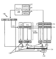
図1は、本開示の一態様によるキャッシュメモリ100のセット間ウェアレベリングのためのキャッシュコントローラ140を含む例示的キャッシュメモリ100の図である。キャッシュメモリ100は、ページ数102、セット数104、バイト数106、キャッシュウェイ108、タグ部分110、データ部分112、キャッシュブロック114、キャッシュセット116、タグセンス増幅器118a、データセンス増幅器118b、タグ出力120、コンパレータ122、論理ゲート124、キャッシュグループ126、選択回路128およびワード出力130を含む。
FIG. 1 is a diagram of an
キャッシュメモリ100内のアドレスは、ページ数102、セット数104およびバイト数106を含み得る。一実装形態で、ページ数102は、仮想ページ数でもよい。セット数104は、キャッシュセット116のうちの1つに対応する。キャッシュブロック114は、タグ部分110およびデータ部分112を含む。タグ部分110は、データ部分112内の実体データのアドレスの部分、またはデータ部分112内のデータを見つけるための他の識別情報を含み得る。データ部分112は、実体データを含む。キャッシュセット116のうちの1つは、図1の水平のグループ分けによって見ることができるような、1セットのキャッシュブロック114である。キャッシュウェイ108は、図1で見ることができるように、キャッシュブロック114の別のグループであるが、垂直のグループ分けにある。タグセンス増幅器118aおよびデータセンス増幅器118bは、データが出力するときに適切に解釈される(1または0として)ように、キャッシュ入力から論理レベルを感知する。
Addresses in
タグセンス増幅器118aの出力である、タグ出力120でのデータは、ページ枠番号、有効ビットおよびコヒーレンスビットを含み得る。タグ出力120からのデータは、次いで、その2つの値が等しいかどうかを確かめるコンパレータ122によってページ数102と比較される。それらの値が等しく、ヒットがある場合、次いで、コンパレータ122の出力が、論理ゲート124に、データセンス増幅器118bの出力とともに、入力される。論理ゲート124の出力がキャッシュグループ126内に現われる。一実装形態で、キャッシュグループ126のうちの1つは、複数のワードを含む。キャッシュグループ126は、選択入力としてバイト数106を使用する選択回路128に入力される。選択入力としてバイト数106を使用する選択回路128の出力は、ワード出力130である。
The data at the
図1はまた、nウェイセットアソシエイティブキャッシュのための例示的ブロック図であり、本開示のために使用される他のタイプのキャッシュが存在し得る。セットアソシエイティブキャッシュは、並行して動作させられるいくつかの直接マップされたキャッシュで構成され得る(たとえば、1つの直接マップされたキャッシュは、タグ部分110およびデータ部分112を含むキャッシュ入力でもよい)。読み取られたデータは、ページ数102ならびにブロック有効ビット(タグまたはメタデータ入力の部分でもよい)およびページ許可(ページ数102の部分)とのタグ比較によって、制御され得る。キャッシュ列サイズはまた、仮想メモリページサイズと同等でもよく、キャッシュインデックスは、ページ数102または仮想ページ数からピットを使用しなくてもよい。
FIG. 1 is also an exemplary block diagram for an n-way set associative cache, and there may be other types of caches used for this disclosure. A set associative cache may consist of several directly mapped caches operated in parallel (e.g., one directly mapped cache may be a cache input that includes a
キャッシュブロック114の個々のキャッシュブロックは、一方向のキャッシュセット116のうちの1つに、そして別の方向のキャッシュウェイ108にグループ分けされる。キャッシュブロック114はまた、どのくらいの頻度でそれらが書き込まれるかに応じて、負荷分散を有し得る。キャッシュブロック114のうちのいくつかは、大量に書き込まれ、キャッシュブロック114のうちの他のキャッシュブロックは、稀に書き込まれる。したがって、これは、セット間書込み変動を引き起こす。セット間書込み変動は、書込み活動に関して異なるキャッシュセット116の間で生じる。すなわち、キャッシュセット116のうちの1つからのキャッシュブロック114は、キャッシュセット116のうちの別のキャッシュセットからのキャッシュブロック114より多くまたは少なく書き込まれ得る。さらに、異なるキャッシュセット116が、キャッシュセット116の他と比べて全体として書き込まれるとき、セット間書込み変動がやはり生じる。
The individual cache blocks of the
本構成で、キャッシュコントローラ140は、キャッシュウェイ108の異なる行におよび異なる列に書込みトラフィックを均等に分散する。図1では、キャッシュウェイ108は列を占有するものとして示され、キャッシュセット116は行を占有するものとして示されるが、キャッシュメモリ100の実装形態はこの構成に限定されない。具体的には、キャッシュウェイ108は、行、またはキャッシュメモリ100内の列でなくてもよい他の構造を占有することがあり、そして、キャッシュセット116は、列、またはキャッシュメモリ100内の行でなくてもよい他の構造を占有することがある。
In this configuration, the
メインメモリウェアレベリング技法は、通常、データ移動を使用してアドレス再マッピングを実装する。これは、メインメモリで、データは失われ得ず、各再マッピングの後に新しい位置に動かすことができるためである。しかしながら、データ移動動作は、常に、エリアおよび性能オーバヘッドを被る。第1に、データ移動は、データを受信するために、一時データ記憶位置を必要とする。第2に、1つのキャッシュセット移動は、いくつかのブロック読取りおよび書込み動作を伴う。したがって、キャッシュポートはデータ移動中に遮断され、システム性能は、結果として、低下させられる。1つの例示的データ移動方式がメインメモリから拡張されてメモリキャッシュに適用されるとき、1つの追加のキャッシュセット(ギャップセット)が追加され、1つのセットからギャップセットへのデータが、定期的に移動させられる。キャッシュ技法は、より性能の影響を受けるので、メインメモリウェアレベリング技法は、直接使用することはできない。したがって、データ移動の使用は、キャッシュセット間ウェアレベリング技法を設計するときに、再考され得る。 Main memory wear leveling techniques typically implement address remapping using data movement. This is because in main memory, data cannot be lost and can be moved to a new location after each remapping. However, data movement operations always incur area and performance overhead. First, data movement requires a temporary data storage location to receive data. Second, one cache set move involves several block read and write operations. Thus, the cache port is blocked during data movement and system performance is consequently reduced. When an exemplary data movement scheme is expanded from main memory and applied to a memory cache, one additional cache set (gap set) is added and data from one set to the gap set is periodically Moved. Since the cache technique is more performance sensitive, the main memory wear leveling technique cannot be used directly. Thus, the use of data movement can be reconsidered when designing an inter-cacheset wear leveling technique.
不揮発性メモリキャッシュのセットアドレス再マッピングを実装するための別のオプションは、データ無効化を実行することである。キャッシュ内のデータはより低レベルのメモリから後で再びリードバックされ得るので、キャッシュライン無効化が使用され得る。キャッシュのこの特別な特徴は、キャッシュセット間ウェアレベリング技法の設計のための新たな好機を提供する。 Another option for implementing non-volatile memory cache set address remapping is to perform data invalidation. Cache line invalidation can be used because the data in the cache can be read back later from lower level memory. This special feature of the cache provides a new opportunity for the design of cache-set wear leveling techniques.
データ移動と比べて、無効化は、エリアオーバヘッドを被らない。したがって、本開示の一態様は、スワップシフトウェアレベリング方式を使用して、不揮発性メモリキャッシュでのセット間書込み変動を低減するために、無効化を使用することによって、以前のメインメモリウェアレベリング技法を修正し、それらを強化する。 Compared to data movement, invalidation does not incur area overhead. Accordingly, one aspect of the present disclosure is that previous main memory wear leveling techniques can be achieved by using invalidation to reduce inter-set write variations in a non-volatile memory cache using a swap shift wear leveling scheme. Fix and strengthen them.
不揮発性メインメモリのための既存のウェアレベリング技法と対照的に、スワップシフト方式は、不揮発性メモリキャッシュのために設計される。スワップシフト方式は、エリアオーバヘッドと性能オーバヘッドの両方を減らすために、セットアドレスマッピングを変更するときにデータ移動の代わりにデータ無効化を使用する。 In contrast to existing wear leveling techniques for non-volatile main memory, the swap shift scheme is designed for non-volatile memory caches. The swap shift scheme uses data invalidation instead of data movement when changing the set address mapping to reduce both area overhead and performance overhead.
スワップシフト方式の一構成は、キャッシュ物理セットのマッピングをシフトさせて、セット間で記憶されたデータを循環させる。しかしながら、一度にすべてのキャッシュセットをシフトさせることは、大きな性能オーバヘッドをもたらす。この問題を解決するために、キャッシュコントローラ140のスワップシフト方式は、一度に2つのセットのマッピングのみをスワップし、すべてのキャッシュセットは、完全なスワップ循環の後に1ステップによりシフトされ得る。
One configuration of the swap shift scheme shifts the mapping of cache physical sets to circulate data stored between sets. However, shifting all cache sets at a time results in significant performance overhead. To solve this problem, the swap shift scheme of the
本構成で、キャッシュコントローラ140は、変数名「numWrite」によって示されるキャッシュへのメモリ書込み動作の数を記憶するためにスワップシフト方式で使用されるグローバルカウンタ142を含む。キャッシュコントローラ140はまた、現在のスワッピング値を記憶するために使用されるスワップレジスタ144(SwapReg)を含む。SwapRegは、最初に0にセットされ、周期的に0からN-1に変更され、Nはキャッシュ内のセットの数である。キャッシュコントローラ140はさらに、現在のシフト値を記憶するシフトレジスタ146(ShiftReg)を含む。ShiftRegは、0からNに周期的に変更される。これらの2つの値、SwapRegおよびShiftRegは、シフト-スワップ方式における2つのタイプの循環、スワップ循環およびシフト循環、を制御するためにキャッシュコントローラ140によって使用される。
In this configuration, the
第1に、スワップ循環が説明される。numWriteが特定の所定の閾値(「閾値」)に等しいとき、SwapRegは値を1増やされ、そして、SwapRegがN-1ステップによって移動されるとき、1つのスワップ循環が生じる。したがって、1つのスワップ循環は、N-1スワップで構成される。 First, swap cycles are explained. When numWrite is equal to a certain predetermined threshold ("threshold"), SwapReg is incremented by 1 and when SwapReg is moved by N-1 steps, one swap cycle occurs. Therefore, one swap cycle consists of N-1 swaps.
第2に、シフト循環が説明される。ShiftRegは、各スワップ循環の後に値を1増やされ、そして、ShiftRegがNステップによって移動されるときに、1つのシフト循環が生じる。したがって、各シフト循環は、Nスワップ循環で構成される。 Second, shift cycling is described. ShiftReg is incremented by 1 after each swap cycle, and one shift cycle occurs when ShiftReg is moved by N steps. Therefore, each shift cycle is composed of N swap cycles.
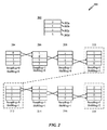
図2は、本開示の一態様によるウェアレベリングのための例示的循環を示す図200である。図200は、キャッシュ構造体202と、循環ボックス204、206、208、210、212、214、216および218のセットとを含む。簡潔性を目的として、キャッシュ構造体202は、キャッシュセット202a、202b、202cおよび202dのグループを有するものとして表されるが、キャッシュ構造体202は、キャッシュブロック114、キャッシュウェイ108またはキャッシュセット116を含む任意の構造体であり、キャッシュメモリ100自体の全体を含み得る。キャッシュ構造体202のキャッシュセットまたは副構造体の数は4つに限定されないが、第1のキャッシュセット202a、第2のキャッシュセット202b、第3のキャッシュセット202cおよび第4のキャッシュセット202dは、図200の循環例のために示される例示的キャッシュセットである。循環プロセスが、ここで説明される。
FIG. 2 is a drawing 200 illustrating an example cycle for wear leveling in accordance with an aspect of the present disclosure. The diagram 200 includes a
循環ボックス204で、キャッシュ構造体202は、初期位置にあり、「0」のラベルを付された第1のキャッシュセット202a、「1」のラベルを付された第2のキャッシュセット202b、「2」のラベルを付された第3のキャッシュセット202c、および「3」のラベルを付された第4のキャッシュセットを伴っている。キャッシュセット202a、202b、202cおよび202dの各々の中に記憶されたデータもまた存在し得る。SwapRegカウンタは、キャッシュセットがスワップされた回数を数える。そのカウンタは、0に初期化され得る。ShiftRegカウンタは、全部のキャッシュ構造体202が位置をシフトされた(キャッシュ構造体202内のすべてのキャッシュセットが1つの位置を移動されたという点で)回数を数え、同様に初期化し、0にセットすることができる。循環のための従来の手法は、一時ブロックを使用し、時間とともにすべてのキャッシュセットまたはキャッシュ構造体を消去する。しかしながら、図200に示す実装形態では、一時ブロックは使用されず、キャッシュセットのデータ内容は削除またはフラッシュされない。データは実際にはスワップされず、同じ位置または位置に保持されるので、これは真である。キャッシュセットの位置のみがスワップされ、スワップされたキャッシュセットのみの内容が消去され、すべての他のキャッシュセットの内容は変わらないままにされる。各々のキャッシュセットもまた、それらの新しい位置に移動され、新しいデータが、データを移動させる必要なしに、新しいキャッシュセットに自動ロードされる。やはり、スワップされる唯一のものは、キャッシュセットの位置である。すべてが、実際にデータを移動させるのではなくて、スワップ動作で行われる。
In the
循環ボックス206で、第1のキャッシュセット202a(0)の位置が、第2のキャッシュセット202b(1)の位置とスワップされる。結果として、第2のキャッシュセット202b(1)は、ここで、本当に最初のまたは最上のキャッシュセットであり、第1のキャッシュセット202a(0)は、第1のキャッシュセット202a(0)の次または下の、第2のキャッシュセットになる。一実装形態で、このスワップが生じた後は、新しいデータが、それらの新しい位置で一度新しいキャッシュセットに自動リロードされることになる。一実装形態では、キャッシュセットがスワップされた後は、新しいデータがそのキャッシュセットに自動リロードされないように、スワップされたキャッシュセットは、それらのデータを保持することになる。キャッシュセットがスワップされた回数を数えるSwapRegカウンタはまた、値を1増やされ得る。循環ボックス208で、第1のキャッシュセット202a(0)の位置(ここでは第2の位置で、第2のキャッシュセット202b(1)の前の位置)が、第3のキャッシュセット202c(2)の位置とスワップされる。ここで、第3のキャッシュセット202c(2)は第2の位置(第2のキャッシュセット202b(1)の元の位置)になり、第1のキャッシュセット202a(0)は第3の位置(第3のキャッシュセット202c(2)の元の位置)になる。SwapRegカウンタは、次いで、再び値を1増やされ得る。
In the
循環ボックス210で、第1のキャッシュセット202a(0)の位置(ここでは第3の位置にある、第3のキャッシュセット202c(2)の前の位置)が、第4のキャッシュセット202d(3)の位置とスワップされる。ここで、第4のキャッシュセット202d(3)は、第3の位置(第3のキャッシュセット202c(2)の元の位置)になり、そして、第1のキャッシュセット202a(0)は第4の位置(第4のキャッシュセット202d(3)の元の位置)になる。すべてのキャッシュセットがシフトされたので、SwapRegカウンタは、次いで、初期化することができ、そして、3回のスワッピングの後に、キャッシュ構造体202内のすべてのレジスタが1つの位置ずつシフトされたので、ShiftRegカウンタが値を増やされる。
In the
続けて循環ボックス212では、第2のキャッシュセット202b(1)の位置が、第3のキャッシュセット202c(2)の位置とスワップされる。ここで、第2のキャッシュセット202b(1)は第2の位置(第3のキャッシュセット202c(2)の元の位置)になり、第3のキャッシュセット202c(2)は第1の位置(第2のキャッシュセット202b(1)の元の位置)になる。SwapRegカウンタはやはり、値を1増やされる。循環ボックス214で、第2のキャッシュセット202b(1)の位置が、第4のキャッシュセット202d(3)の位置とスワップされる。ここで、第4のキャッシュセット202d(3)は第2の位置(第2のキャッシュセット202b(1)の元の位置)になり、そして、第4のキャッシュセット202d(3)は第2の位置(第2のキャッシュセット202b(1)の元の位置)になる。SwapRegカウンタはやはり、値を1増やされる。循環ボックス216で、第2のキャッシュセット202b(1)の位置が、第1のキャッシュセット202a(0)の位置とスワップされる。ここで、第2のキャッシュセット202b(1)は、第4の位置(第1のキャッシュセット202a(0)の元の位置)になり、そして、第1のキャッシュセット202a(0)は第3の位置(第2のキャッシュセット202b(1)の元の位置)になる。SwapRegカウンタは、次いで、初期化され、そして、別の3回のスワッピングの後に、キャッシュ構造体202内のすべてのレジスタが2つの位置だけシフトされたので、ShiftRegカウンタは、値を1増やす。
Subsequently, in the
一実装形態で、すべてがスワップ動作によって行われるので、全キャッシュの内容はフラッシュされない。さらに、スワップ動作は、性能低下を伴わない。スワップ動作を使用してスワッピングを実行することによって、「シフトアップ」動作および/または追跡は生じない。一実装形態で、データはスワップされず、単に位置、およびデータが、次いで、新しいスワップされた位置にリロードされる。一実装形態で、無効なキャッシュセットなど、未使用の位置のデータは、単純に破棄される。一実装形態で、1つのスワップについて、SwapRegカウンタ位置(たとえば、キャッシュレジスタ[SwapReg])に対応するキャッシュセットの内容と、SwapRegカウンタ足す1(たとえば、キャッシュレジスタ[SwapReg+1])に対応するキャッシュセットの内容とが、破棄され得る。次いで、それらの物理的位置がスワップされる。Nがキャッシュ構造体内のキャッシュセットの数であり、N-1スワップの後、キャッシュ構造体(各々のキャッシュセット)内のすべての物理的位置が、すべて1ずつシフトされる。 In one implementation, the entire cache contents are not flushed because everything is done by swap operations. Furthermore, the swap operation is not accompanied by a performance degradation. By performing swapping using a swap operation, no "shift up" operation and / or tracking occurs. In one implementation, the data is not swapped, just the location and the data is then reloaded to the new swapped location. In one implementation, data at unused locations, such as an invalid cache set, is simply discarded. In one implementation, for one swap, the contents of the cache set corresponding to the SwapReg counter location (eg, cache register [SwapReg]) and the cache corresponding to the SwapReg counter plus 1 (eg, cache register [SwapReg + 1]) The contents of the set can be discarded. Their physical locations are then swapped. N is the number of cache sets in the cache structure, and after N-1 swap, all physical locations in the cache structure (each cache set) are all shifted by one.
一実装形態で、SwapRegおよびShiftRegカウンタは、図1に示すように、データを記憶するためのキャッシュコントローラ140のスワップレジスタ144およびシフトレジスタ146として実装することができる。この場合、レジスタは、それらのそれぞれのカウンタの値を記録するある種の数値データとして実装される。
In one implementation, the SwapReg and ShiftReg counters may be implemented as a
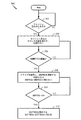
図3は、本開示の一態様によるキャッシュメモリのウェアレベリングのためのキャッシュコントローラの動作を示す論理フローチャート300である。図3は、ShiftRegおよびSwapRegカウンタが書込み活動に関してウェアレベリングシステムでどのように更新されるかを示す。ブロック302で、キャッシュ書込みがあったかどうかが、判定される。キャッシュ書込みがあった場合、次いで、ブロック304で、「numWrite」として知られるキャッシュ書込みカウンタが値を1増やされる。キャッシュ書込みがなかった場合、本プロセスは、ブロック302の前に戻る。numWriteカウンタはまた、いつスワップするかをトリガする。キャッシュセットのスワップを起動するためにいくつの書込みが十分であるかを判定する何らかの所定の閾値もまた存在する。たとえば、ブロック306で、numWriteカウンタが所定の閾値に等しいかどうかが判定される。そうである場合、次いでブロック308で、numWriteカウンタをゼロ値に更新し、SwapRegカウンタを(SwapReg+1)mod(N-1)の値に更新して、スワップが起動される。modはモジュロ演算子であり、Nは選択されたキャッシュ構造体内のキャッシュセットの総数である。ブロック306で、numWriteカウンタが所定の閾値に等しくない場合、次いで、プロセスはブロック304に戻る。ブロック310で、SwapRegカウンタがゼロに等しいかどうかが判定される。そうである場合、次いでブロック312で、ShiftRegカウンタが、(ShiftReg+1)mod Nの値に更新される。これは、全キャッシュ構造体を1ずつシフトさせる。ブロック310で、SwapRegカウンタの値がゼロに等しくない場合、次いで、プロセスはブロック308に戻る。
FIG. 3 is a
図3はまた、次の疑似コードによって表すことができる:
If (キャッシュ書込みがある),
then: numWrite++;
If (numWrite == 閾値),
then: numWrite = 0;
then: SwapReg = (SwapReg + 1) mod (N-1);
if (SwapReg ==0),
then: ShiftReg = (ShiftReg + 1) mod (N).
Figure 3 can also be represented by the following pseudocode:
If (with cache write),
then: numWrite ++;
If (numWrite == threshold),
then: numWrite = 0;
then: SwapReg = (SwapReg + 1) mod (N-1);
if (SwapReg == 0),
then: ShiftReg = (ShiftReg + 1) mod (N).
図4は、本開示の一態様によるキャッシュメモリのウェアレベリングのためのキャッシュコントローラの動作を示す論理フローチャート400である。図4は、書込みの数を表すnumWriteカウンタを記憶するグローバルカウンタ404を示し、各書込みはキャッシュ書込みアクション402によって表される。SwapRegカウンタ(「SwapReg」として反映される)およびShiftRegカウンタ(「ShiftReg」として表現される)が、SwapRegおよびShiftReg値をそれぞれ記憶するためのデータレジスタとして実装され得る。
FIG. 4 is a logic flow diagram 400 illustrating the operation of a cache controller for wear leveling of a cache memory according to one aspect of the present disclosure. FIG. 4 shows a
図3に関して説明したように、キャッシュ書込み402が存在する場合、次いで、グローバルカウンタ404が増やされる。406でグローバルカウンタが所定の閾値に等しい場合、ブロック408で、SwapRegカウンタを(SwapReg+1)mod(N-1)の値に更新して、スワップが生じ、modはモジュロ演算子であり、Nは全キャッシュセットの数である。SwapRegがゼロである場合(410)、次いでブロック412で、ShiftRegカウンタが、(ShiftReg+1)mod Nの値に更新される。
As described with respect to FIG. 3, if there is a
論理セット(LS)数が論理セット数入力414として入るとき、物理セット(PS)数が、3つの異なる状況に基づいて物理セット数出力418として計算され得る。
When a logical set (LS) number is entered as a logical
第1に、論理ボックス416に示すように、論理セット数入力414がSwapReg値に等しい場合、それは、この論理セットがまさしく、この循環でスワップされるべきキャッシュセットであることを意味する。したがって、その物理セットが、ShiftRegの現在のシフト値にマップされ、物理セット数出力418として出力される。
First, as shown in
第2に、やはり論理ボックス416に示すように、論理セット数入力414がSwapReg値より大きい場合、それは、このキャッシュセットがこの循環でシフトされず、最後の循環と同じマッピングを保持することを意味する。したがって、その物理セットは、LS+ShiftRegにマップされる。一実装形態で、そのマッピングは、(LS+ShiftReg)値を選び、N、すなわちキャッシュセットの数で、モジュロ演算を実行し、次いで、結果として生じた値を物理セットに割り当てることによって、行われる。
Second, as also shown in
第3に、やはり論理ボックス416に示すように、論理セット数入力414がSwapReg値よりも小さい場合(else節)、それは、このキャッシュセットがこの循環でシフトされたことを意味する。したがって、物理セットは、LS+ShiftReg+1にマップされる。一実装形態で、マッピングは、(LS+ShiftReg+1)値を選び、N、すなわちキャッシュセットの数で、モジュロ演算を実行し、次いで、結果として生じた値を物理セットに割り当てることによって、行われる。
Third, also as shown in
論理セット数出力420を計算するための物理セット入力数424を別にすれば、前述の動作と同様の3つの動作が、論理ボックス422で生じる。
Apart from the physical
キャッシュラインが、より低レベルのメモリに書き戻される必要があるとき、論理セットアドレスが再生成される。物理セットから論理セットへのマッピングは、対称である。このマッピング方式はまた、図2に見られるように確認することができる。SwapRegおよびShiftRegは、書込みカウントを増やすこととともに変更されるので、論理セットと物理セットの間のマッピングはいつでも変化し、異なる物理セットへの書込みのバランスがとられることを確保し、書込み変動を低減する。 When the cache line needs to be written back to lower level memory, the logical set address is regenerated. The mapping from the physical set to the logical set is symmetric. This mapping scheme can also be confirmed as seen in FIG. SwapReg and ShiftReg change with increasing write count, so the mapping between logical and physical sets changes at any time, ensuring that writes to different physical sets are balanced and reduces write variation To do.
従来のキャッシュアーキテクチャと比べて、シフト-スワップウェアレベリング方式におけるセットインデックス変換は、単純な算術演算のみを追加し、行復号器に組み込むことができる。加えて、この1周期待機時間オーバヘッドは、より低レベルのキャッシュにアクセスするより高レベルのキャッシュミスでのみ払われる。 Compared with the conventional cache architecture, the set index conversion in the shift-swap wear leveling scheme can add only a simple arithmetic operation and can be incorporated into the row decoder. In addition, this one-cycle latency overhead is paid only for higher level cache misses that access lower level caches.
図5は、本開示の一態様によるウェアレベリングのための方法を示すプロセスフローチャート500である。ブロック502で、メモリ書込み動作の数が、メモリ書込み動作ごとに1ずつグローバルカウンタの値を増やすことによって、グローバルカウンタによって数えられる。ブロック504で、グローバルカウンタが所定の閾値に等しいとき、スワップ動作が実行され、スワップカウンタが値を1だけ増やされる。また、スワップ動作の実行は、スワップされるキャッシュセットを再マップするステップを含み、このステップは、2つのスワップされるキャッシュセット内の汚染データを書き戻しバッファに置くステップと、2つのスワップされるキャッシュセット内のその他のデータを無効にするステップとを含む。
FIG. 5 is a
ブロック506で、スワップカウンタがN-1に等しいとき、シフトカウンタは値を1増やされ、スワップカウンタがゼロに戻される。Nは、そのキャッシュメモリ内のキャッシュセットの数である。ブロック508で、シフトカウンタがNに等しいとき、シフトカウンタがゼロに戻される。ブロック510で、入力キャッシュセット数が、出力キャッシュセット数に変換される。入力または出力キャッシュセット数は、論理セット数または物理セット数でもよい。
At
図6は、本開示の一態様によるウェアレベリングのための方法を示すプロセスフローチャート600である。ブロック610で、キャッシュメモリへのメモリ書込み動作の数(たとえば、numWrite)が所定の閾値に達したかどうかが判定される。そうである場合、ブロック612で、メモリ位置スワップ動作が、2つのキャッシュセットに実行される。ブロック614で、それらの2つのスワップされたキャッシュセットのうちの1つの内容が消去される。ブロック616で、スワップされた2つのキャッシュセットの他方のメモリ内容は、そのままにされる。ブロック618で、キャッシュセットのスワッピングが追跡される。ブロック620で、論理キャッシュセット数が、物理キャッシュセット数に変換される。書込み動作の数が閾値に到達していない場合、本プロセスは、ブロック610に留まる。
FIG. 6 is a
スワップシフトウェアレベリング方式で、セット間書込み変動の低減は、実験時間中のシフト循環回数に関連する。キャッシュ内にNセットがあると仮定すると、1つのシフト循環はNスワップ循環を含み、スワップシフト方式での1つのスワップ循環はN-1スワップを必要とする。各シフト循環の後、すべてのキャッシュセットが、Nステップだけシフトされ、論理セットインデックスは、それらの元の位置にマップされる。したがって、キャッシュがシフトされる回数が多いほど、書込みアクセスはより均等に各キャッシュセットに分散される。 In the swap shift wear leveling method, the reduction in inter-set write variation is related to the number of shift cycles during the experiment time. Assuming there are N sets in the cache, one shift cycle includes N swap cycles, and one swap cycle in the swap shift scheme requires N-1 swaps. After each shift cycle, all cache sets are shifted by N steps and the logical set index is mapped to their original location. Thus, the greater the number of times the cache is shifted, the more evenly the write access is distributed across each cache set.
本開示のさらなる態様によれば、キャッシュメモリのウェアレベリングのためのキャッシュコントローラが説明される。本キャッシュコントローラは、キャッシュメモリへのメモリ書込み動作の数が閾値に達するときにキャッシュセットに対する複数のメモリ位置スワップ動作を実行することによってキャッシュメモリのキャッシュセットを動的に循環させるための手段を含む。各スワップ動作は、他のキャッシュセットのメモリ内容はそのままにしながら、スワップされたキャッシュセットのみの内容を消去するステップを含み得る。動的に循環させる手段は、キャッシュコントローラ140でもよい。その装置はさらに、スワップされたキャッシュセットを追跡して論理キャッシュセット数を物理キャッシュセット数に変換するための手段を含む。その追跡手段は、キャッシュコントローラ140、グローバルカウンタ142、スワップレジスタ144、および/またはシフトレジスタ146でもよい。別の態様で、前述の手段は、任意のモジュール、または、前述の手段で挙げられた機能を実行するように構成された任意の装置でもよい。
According to a further aspect of the present disclosure, a cache controller for wear leveling of a cache memory is described. The cache controller includes means for dynamically cycling the cache set of cache memory by performing multiple memory location swap operations on the cache set when the number of memory write operations to the cache memory reaches a threshold. . Each swap operation may include erasing only the contents of the swapped cache set while leaving the memory contents of the other cache sets intact. The means for dynamically circulating may be the
図7は、本開示の一態様が有利には使用され得る例示的ワイヤレス通信システム700を示すブロック図である。説明を目的として、図7は、3つの遠隔装置720、730、および750と、2つの基地局740とを示す。ワイヤレス通信システムはさらに多数の遠隔装置および基地局を有し得ることが、理解されよう。遠隔装置720、730、および750は、開示されるキャッシュメモリを含むICデバイス725A、725C、および725Bを含む。基地局、スイッチングデバイス、およびネットワーク機器など、他のデバイスもまた、開示されるキャッシュメモリを含み得ることが、理解されよう。図7は、基地局740から遠隔装置720、730、および750への順方向リンク信号780と、遠隔装置720、730、および750から基地局740への逆方向リンク信号790とを示す。
FIG. 7 is a block diagram illustrating an example
図7で、遠隔装置720は、携帯電話として示され、遠隔装置730はポータブルコンピュータとして示され、遠隔装置750はワイヤレスローカルループシステム内の定位置遠隔装置として示される。たとえば、その遠隔装置は、携帯電話、ハンドヘルドパーソナル通信システム(PCS)ユニット、パーソナルデータアシスタントなどのポータブルデータユニット、グローバルポジショニングシステム(GPS)対応デバイス、ナビゲーションデバイス、セットトップボックス、音楽プレーヤ、ビデオプレーヤ、エンタテイメントユニット、メータ読取り機器などの定位置データユニット、あるいは、データもしくはコンピュータ命令またはそれらの組合せを記憶または検索する他のデバイスでもよい。図7は、本開示の態様による遠隔装置を示すが、本開示は、これらの例示的な図示されたユニットに限定されない。本開示の態様は、開示されたキャッシュメモリを含む、多数のデバイスで適切に使用され得る。
In FIG. 7,
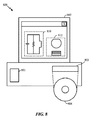
図8は、前述で開示されたキャッシュメモリなど、半導体構成要素の回路、レイアウト、および論理設計のために使用される設計ワークステーションを示すブロック図である。設計ワークステーション800は、オペレーティングシステムソフトウェア、サポートファイル、および、CadenceまたはOrCADなどの設計ソフトウェアを含む、ハードディスク801を含む。設計ワークステーション800はまた、回路810またはキャッシュメモリなどの半導体構成要素812の設計を容易にするためのディスプレイ802を含む。記憶媒体804は、回路設計810または半導体構成要素812を実体的に記憶するために提供される。回路設計810または半導体構成要素812は、GDSIIまたはGERBERなどのファイル形式で記憶媒体804に記憶され得る。記憶媒体804は、CD-ROM、デジタル多用途ディスク(DVD)、ハードディスク、フラッシュメモリ、または他の適切なデバイスでもよい。さらに、設計ワークステーション800は、記憶媒体804から入力を受け付けるまたは記憶媒体804に出力を書き込むためのドライブ装置803を含む。
FIG. 8 is a block diagram illustrating a design workstation used for circuit, layout, and logic design of semiconductor components, such as the cache memory disclosed above. The design workstation 800 includes a hard disk 801 that includes operating system software, support files, and design software such as Cadence or OrCAD. The design workstation 800 also includes a
記憶媒体804に記録されたデータは、論理回路構成、フォトリソグラフィマスクのパターンデータ、または、電子ビームリソグラフィなどの順次書込みツールのためのマスクパターンデータを指定することができる。そのデータはさらに、タイミング図または論理シミュレーションに関連するネット回路などの論理検証データを含み得る。記憶媒体804でのデータの提供は、半導体ウエハを設計するためのプロセスの数を減らすことによって、回路設計810または半導体構成要素812の設計を容易にする。
The data recorded in the
ファームウェアおよび/またはソフトウェア実装について、本方法論は、本明細書に記載された機能を実行するモジュール(たとえば、手順、機能など)で実装することができる。命令を実体的に実施する機械可読媒体が、本明細書に記載された方法論の実装で使用され得る。たとえば、ソフトウェアコードは、メモリで記憶することができ、プロセッサユニットによって実行することができる。メモリは、プロセッサユニット内でまたはプロセッサユニットの外部で実装することができる。本明細書で、「メモリ」という用語は、長期、短期、揮発性、不揮発性、または他のメモリのタイプを指し、特定のタイプのメモリまたはメモリの数、あるいは、メモリが記憶される媒体のタイプに限定されるべきではない。 For firmware and / or software implementations, the methodology may be implemented with modules (eg, procedures, functions, etc.) that perform the functions described herein. Any machine-readable medium that materially implements the instructions may be used in the implementation of the methodology described herein. For example, software code can be stored in memory and executed by a processor unit. The memory can be implemented within the processor unit or external to the processor unit. As used herein, the term “memory” refers to a long-term, short-term, volatile, non-volatile, or other type of memory, a specific type of memory or number of memories, or the medium on which the memory is stored. Should not be limited to type.
ファームウェアおよび/またはソフトウェアで実装される場合、その機能は、コンピュータ可読媒体に1つまたは複数の命令またはコードとして記憶され得る。例は、データ構造体でコード化されたコンピュータ可読媒体、および、コンピュータプログラムでコード化されたコンピュータ可読媒体を含む。コンピュータ可読媒体は、物理コンピュータ記憶媒体を含む。記憶媒体は、コンピュータによってアクセスすることができる使用可能な媒体でもよい。例として、そして限定ではなく、そのようなコンピュータ可読媒体は、RAM、ROM、EEPROM、CD-ROMまたは他の光ディスク記憶装置、磁気ディスク記憶装置または他の磁気記憶デバイス、あるいは、命令またはデータ構造体の形で所望のプログラムコードを記憶するために使用することができる、およびコンピュータによってアクセスすることができる他の媒体を含むことができ、本明細書で、ディスク(diskまたはdisc)は、コンパクトディスク(CD)、レーザディスク、光ディスク、デジタル多用途ディスク(DVD)、フロッピー(登録商標)ディスク、および、ブルーレイディスクを含み、ディスク(disk)は通常は、データを磁気的に再生し、一方、ディスク(disc)は、レーザで光学的にデータを再生する。前述の組合せもまた、コンピュータ可読媒体の範囲に含まれよう。 If implemented in firmware and / or software, the functions may be stored as one or more instructions or code on a computer-readable medium. Examples include computer readable media encoded with a data structure and computer readable media encoded with a computer program. Computer-readable media includes physical computer storage media. A storage media may be any available media that can be accessed by a computer. By way of example and not limitation, such computer readable media can be RAM, ROM, EEPROM, CD-ROM or other optical disk storage, magnetic disk storage or other magnetic storage device, or instructions or data structures Can include other media that can be used to store desired program code in the form of, and can be accessed by a computer, where a disk (disc or disc) is a compact disc (CD), laser discs, optical discs, digital versatile discs (DVD), floppy discs, and Blu-ray discs, which usually play data magnetically while discs (disc) reproduces data optically with a laser. Combinations of the above will also be included within the scope of computer-readable media.
コンピュータ可読媒体での記憶に加えて、命令および/またはデータは、通信装置に含まれる送信媒体で信号として提供され得る。たとえば、通信装置は、命令およびデータを示す信号を有する送受信機を含み得る。その命令およびデータは、特許請求の範囲で概説される機能を1つまたは複数のプロセッサに実装させるように構成される。 In addition to being stored on a computer readable medium, the instructions and / or data may be provided as signals on a transmission medium included in the communication device. For example, the communication device may include a transceiver having signals indicative of instructions and data. The instructions and data are configured to cause one or more processors to implement the functions outlined in the claims.
本開示およびその利点が詳細に説明されたが、様々な変更、置換、および代替が、添付の特許請求の範囲によって定義されるものとしての本開示の技術を逸脱することなしに本明細書で行われ得ることを理解されたい。たとえば、「上」および「下」などの関係語が、基材または電子デバイスに関して使用される。もちろん、基材または電子デバイスが反転させられた場合、上は下になり、その逆も同様である。加えて、横向きにされた場合、上および下は、基材または電子デバイスの側面を指すことがある。さらに、本出願の範囲は、本明細書に記載されたプロセス、機械、製品、組成物、手段、方法およびステップの特定の構成に限定されるものではない。本明細書に記載された対応する構成と同じ機能を実質的に実行するまたは同じ結果を実質的に達成する、現在存在するまたは後から開発される、プロセス、機械、製品、組成物、手段、方法、またはステップは、本開示に従って使用され得ることが、本開示から当業者には容易に理解されよう。したがって、添付の特許請求の範囲は、そのようなプロセス、機械、製品、組成物、手段、方法、またはステップをその範囲に含むものとする。 Although the present disclosure and its advantages have been described in detail, various changes, substitutions, and alternatives may be made herein without departing from the technology of the present disclosure as defined by the appended claims. It should be understood that this can be done. For example, related terms such as “above” and “below” are used with respect to a substrate or an electronic device. Of course, if the substrate or electronic device is inverted, the top will be down and vice versa. In addition, when placed sideways, top and bottom may refer to the sides of the substrate or electronic device. Further, the scope of the present application is not limited to the particular configuration of processes, machines, products, compositions, means, methods and steps described herein. A process, machine, product, composition, means, present or later developed that substantially performs the same function as the corresponding configuration described herein or substantially achieves the same result, Those of skill in the art will readily appreciate from the present disclosure that methods or steps may be used in accordance with the present disclosure. Accordingly, the appended claims are intended to include within their scope such processes, machines, manufacture, compositions of matter, means, methods, or steps.
100 キャッシュメモリ
102 ページ数
104 セット数
106 バイト数
108 キャッシュウェイ
110 タグ部分
112 データ部分
114 キャッシュブロック
116 キャッシュセット
118a タグセンス増幅器
118b データセンス増幅器
120 タグ出力
122 コンパレータ
124 論理ゲート
126 キャッシュグループ
128 選択回路
130 ワード出力
140 キャッシュコントローラ
142 グローバルカウンタ
144 スワップレジスタ
146 シフトレジスタ
202 キャッシュ構造体
202a キャッシュセット
202b キャッシュセット
202c キャッシュセット
202d キャッシュセット
204 循環ボックス
206 循環ボックス
208 循環ボックス
210 循環ボックス
212 循環ボックス
214 循環ボックス
216 循環ボックス
218 循環ボックス
402 キャッシュ書込みアクション
404 グローバルカウンタ
414 論理セット数入力
416 論理ボックス
418 物理セット数出力
420 論理セット数出力
422 論理ボックス
424 物理セット入力数
700 ワイヤレス通信システム
720 遠隔装置
725A ICデバイス
725B ICデバイス
725C ICデバイス
730 遠隔装置
740 基地局
750 遠隔装置
780 順方向リンク信号
790 逆方向リンク信号
800 設計ワークステーション
801 ハードディスク
802 ディスプレイ
803 ドライブ装置
804 記憶媒体
810 回路
812 半導体構成要素
100 cache memory
102 pages
104 sets
106 bytes
108 Cash Way
110 Tag part
112 Data part
114 cache blocks
116 cash set
118a tag sense amplifier
118b Data sense amplifier
120 tag output
122 Comparator
124 logic gate
126 cash group
128 selection circuit
130 word output
140 Cache controller
142 Global counter
144 Swap register
146 Shift register
202 Cache structure
202a cache set
202b cache set
202c cache set
202d cache set
204 Circulation box
206 Circulation box
208 Circulation box
210 Circulation box
212 Circulation box
214 circulation box
216 Circulation box
218 Circulation box
402 Cache write action
404 global counter
414 Logical set number input
416 logical box
418 Number of physical sets output
420 Number of logical sets output
422 logical box
424 Number of physical set inputs
700 wireless communication system
720 remote device
725A IC device
725B IC device
725C IC device
730 remote device
740 base station
750 remote device
780 Forward link signal
790 Reverse link signal
800 design workstation
801 hard disk
802 display
803 drive unit
804 storage media
810 circuit
812 Semiconductor components
Claims (20)
前記キャッシュメモリへのメモリ書込み動作の数が閾値に達するときにキャッシュセットに対する複数のメモリ位置スワップ動作を実行することによって前記キャッシュメモリの前記キャッシュセットを動的に循環させるステップであって、各スワップ動作が、他のキャッシュセットのメモリ内容はそのままにしながら、スワップされたキャッシュセットのみの内容を消去するステップを含む、ステップと、
前記スワップされたキャッシュセットを追跡して論理キャッシュセット数を物理キャッシュセット数に変換するステップと
を含む、方法。 A method for wear leveling of a cache memory,
Dynamically cycling the cache set of the cache memory by performing a plurality of memory location swap operations for the cache set when the number of memory write operations to the cache memory reaches a threshold, An operation comprising erasing the contents of only the swapped cache set while leaving the memory contents of the other cache sets intact; and
Tracking the swapped cache set and converting a logical cache set number to a physical cache set number.
グローバルカウンタで前記キャッシュメモリへのメモリ書込み動作の数を数えるステップと、
前記グローバルカウンタが前記閾値に達するときに前記複数のメモリ位置スワップ動作を起動させるステップと、
前記グローバルカウンタをリセットするステップと
をさらに含む、請求項1に記載の方法。 Dynamically cycling the cache set further comprises:
Counting the number of memory write operations to the cache memory with a global counter;
Activating the plurality of memory location swap operations when the global counter reaches the threshold;
The method of claim 1, further comprising: resetting the global counter.
Nが前記キャッシュメモリ内の前記キャッシュセットの数であり、スワップレジスタ(SwapReg)を(前記SwapReg+1)mod(N-1)にセットするステップと、
前記SwapRegがゼロであるときにシフトレジスタ(ShiftReg)を(前記ShiftReg+1)mod Nにセットするステップと
を含む、請求項2に記載の方法。 Dynamically cycling the cache set comprises:
N is the number of the cache sets in the cache memory, and setting a swap register (SwapReg) to (the SwapReg + 1) mod (N-1);
3. A method according to claim 2, comprising: setting a shift register (ShiftReg) to (the ShiftReg + 1) mod N when the SwapReg is zero.
前記グローバルカウンタが閾値に等しいときに、前記スワップされたキャッシュセットを再マップするステップを含むスワップ動作を実行し、スワップカウンタの値を増やすステップと、
Nが前記キャッシュメモリ内の前記キャッシュセットの数であり、スワップカウンタ値がN-1に等しいときに、シフトカウンタの値を増やし、前記スワップカウンタ値をリセットするステップと、
シフトカウンタ値がNに等しいときに、前記シフトカウンタをリセットするステップと
をさらに含む、請求項1に記載の方法。 Counting the number of memory write operations to the cache memory with the global counter by increasing the value of the global counter for each memory write operation to the cache memory;
Performing a swap operation including re-mapping the swapped cache set when the global counter is equal to a threshold, and increasing the value of the swap counter;
N is the number of the cache sets in the cache memory, and when the swap counter value is equal to N-1, increasing the value of the shift counter and resetting the swap counter value;
The method of claim 1, further comprising: resetting the shift counter when a shift counter value is equal to N.
書き戻しバッファに前記スワップされたキャッシュセット内の汚染データを記憶するステップと、
前記スワップされたキャッシュセット内の他のデータを無効にするステップと
を含む、請求項4に記載の方法。 Remapping the swapped cache set comprises:
Storing tainted data in the swapped cache set in a write-back buffer;
5. The method of claim 4, comprising invalidating other data in the swapped cache set.
入力論理セット数が前記スワップカウンタ値に等しいときに出力物理セット数を前記シフトカウンタ値にセットするステップと、
前記入力論理セット数が前記スワップカウンタ値より大きいときに前記出力物理セット数を(前記入力論理セット数+前記シフトカウンタ値)modulo Nにセットするステップと、
前記入力論理セット数が前記スワップカウンタ値より小さいときに前記出力物理セット数を(前記入力論理セット数+前記シフトカウンタ値+1)modulo Nにセットするステップと
を含む、請求項4に記載の方法。 The step of converting the number of input cache sets to the number of output cache sets is:
Setting the output physical set number to the shift counter value when the input logical set number is equal to the swap counter value;
Setting the output physical set number to (modulus N) (the input logical set number + the shift counter value) when the input logical set number is greater than the swap counter value;
And setting the output physical set number to (the input logical set number + the shift counter value + 1) modulo N when the input logical set number is smaller than the swap counter value. Method.
入力物理セット数が前記シフトカウンタ値に等しいときに出力論理セット数を前記スワップカウンタ値にセットするステップと、
(前記入力物理セット数-前記シフトカウンタ値)modulo Nが前記スワップカウンタ値より大きいときに前記出力論理セット数を(前記入力物理セット数-前記シフトカウンタ値)modulo Nにセットするステップと、
その他の場合に、前記出力論理セット数を(前記入力物理セット数-前記シフトカウンタ値-1)modulo Nにセットするステップと
を含む、請求項4に記載の方法。 Tracking the swapped cache set comprises:
Setting the output logical set number to the swap counter value when the input physical set number is equal to the shift counter value;
(The input physical set number-the shift counter value) when the modulo N is larger than the swap counter value, the output logical set number is set to (the input physical set number-the shift counter value) modulo N;
5. In other cases, the method comprises: setting the output logical set number to (the input physical set number−the shift counter value−1) modulo N.
前記キャッシュメモリの前記複数のキャッシュセットに対するあらゆるN-1メモリ位置スワップ動作の後に更新し、(N2-N)メモリ位置スワップ動作ごとにリセットする、第2のレジスタと
を備え、前記第1のレジスタおよび前記第2のレジスタが、前記キャッシュセットの論理的位置と物理的位置との関係を追跡する、キャッシュコントローラ。 A first register, wherein N is the number of cache sets in the cache memory, updated after each memory location swap operation for multiple cache sets of cache memory and reset with each N-1 memory location swap operation;
A second register that updates after every N-1 memory location swap operation for the plurality of cache sets of the cache memory and resets every (N 2 -N) memory location swap operation; and A cache controller, wherein a register and the second register track a relationship between a logical position and a physical position of the cache set.
前記第2のレジスタが、前記SwapRegがゼロに等しいときに(ShiftReg+1)mod Nにセットされるシフトレジスタ(ShiftReg)である、請求項9に記載のキャッシュコントローラ。 The first register is a swap register (SwapReg) that is set to (SwapReg + 1) mod (N-1) when a memory swap operation is performed,
10. The cache controller according to claim 9, wherein the second register is a shift register (ShiftReg) that is set to (ShiftReg + 1) mod N when the SwapReg is equal to zero.
前記キャッシュメモリへのメモリ書込み動作の数が閾値に達するときにキャッシュセットに対する複数のメモリ位置スワップ動作を実行することによって前記キャッシュメモリの前記キャッシュセットを動的に循環させるための手段であって、各スワップ動作が、他のキャッシュセットのメモリ内容はそのままにしながら、スワップされたキャッシュセットのみの内容を消去するステップを含む、手段と、
前記スワップされたキャッシュセットを追跡して論理キャッシュセット数を物理キャッシュセット数に変換するための手段と
を備える、キャッシュコントローラ。 A cache controller for wear leveling of cache memory,
Means for dynamically cycling the cache set of the cache memory by performing a plurality of memory location swap operations on the cache set when the number of memory write operations to the cache memory reaches a threshold; Means for each swap operation comprising erasing only the contents of the swapped cache set while leaving the memory contents of the other cache sets intact;
Means for tracking said swapped cache set and converting a logical cache set number to a physical cache set number.
前記キャッシュメモリへのメモリ書込み動作の数が閾値に達するときにキャッシュセットに対する複数のメモリ位置スワップ動作を実行することによって前記キャッシュメモリの前記キャッシュセットを動的に循環させるステップであって、各スワップ動作が、他のキャッシュセットのメモリ内容はそのままにしながら、スワップされたキャッシュセットのみの内容を消去するステップを含む、ステップと、
前記スワップされたキャッシュセットを追跡して論理キャッシュセット数を物理キャッシュセット数に変換するステップと
を含む、方法。 A method for wear leveling of a cache memory,
Dynamically cycling the cache set of the cache memory by performing a plurality of memory location swap operations for the cache set when the number of memory write operations to the cache memory reaches a threshold, An operation comprising erasing the contents of only the swapped cache set while leaving the memory contents of the other cache sets intact; and
Tracking the swapped cache set and converting a logical cache set number to a physical cache set number.
Applications Claiming Priority (3)
| Application Number | Priority Date | Filing Date | Title |
|---|---|---|---|
| US13/772,400 US9348743B2 (en) | 2013-02-21 | 2013-02-21 | Inter-set wear-leveling for caches with limited write endurance |
| US13/772,400 | 2013-02-21 | ||
| PCT/US2014/015994 WO2014130317A1 (en) | 2013-02-21 | 2014-02-12 | Inter-set wear-leveling for caches with limited write endurance |
Publications (2)
| Publication Number | Publication Date |
|---|---|
| JP2016507847A true JP2016507847A (en) | 2016-03-10 |
| JP2016507847A5 JP2016507847A5 (en) | 2016-08-25 |
Family
ID=50272693
Family Applications (1)
| Application Number | Title | Priority Date | Filing Date |
|---|---|---|---|
| JP2015558874A Ceased JP2016507847A (en) | 2013-02-21 | 2014-02-12 | Inter-set wear leveling for caches with limited write endurance |
Country Status (6)
| Country | Link |
|---|---|
| US (1) | US9348743B2 (en) |
| EP (1) | EP2959390A1 (en) |
| JP (1) | JP2016507847A (en) |
| KR (1) | KR20150119921A (en) |
| CN (1) | CN105009093A (en) |
| WO (1) | WO2014130317A1 (en) |
Families Citing this family (21)
| Publication number | Priority date | Publication date | Assignee | Title |
|---|---|---|---|---|
| US9292451B2 (en) | 2013-02-19 | 2016-03-22 | Qualcomm Incorporated | Methods and apparatus for intra-set wear-leveling for memories with limited write endurance |
| KR20150062039A (en) * | 2013-11-28 | 2015-06-05 | 에스케이하이닉스 주식회사 | Semiconductor device and operating method thereof |
| US9239679B2 (en) * | 2013-12-19 | 2016-01-19 | Avago Technologies General Ip (Singapore) Pte. Ltd. | System for efficient caching of swap I/O and/or similar I/O pattern(s) |
| US9053790B1 (en) * | 2014-07-01 | 2015-06-09 | Sandisk Technologies Inc. | Counter for write operations at a data storage device |
| US9251909B1 (en) | 2014-09-29 | 2016-02-02 | International Business Machines Corporation | Background threshold voltage shifting using base and delta threshold voltage shift values in flash memory |
| US10127157B2 (en) * | 2014-10-06 | 2018-11-13 | SK Hynix Inc. | Sizing a cache while taking into account a total bytes written requirement |
| US10452560B2 (en) | 2015-07-14 | 2019-10-22 | Western Digital Technologies, Inc. | Wear leveling in non-volatile memories |
| US10445232B2 (en) | 2015-07-14 | 2019-10-15 | Western Digital Technologies, Inc. | Determining control states for address mapping in non-volatile memories |
| US10452533B2 (en) | 2015-07-14 | 2019-10-22 | Western Digital Technologies, Inc. | Access network for address mapping in non-volatile memories |
| US10445251B2 (en) | 2015-07-14 | 2019-10-15 | Western Digital Technologies, Inc. | Wear leveling in non-volatile memories |
| US9921969B2 (en) | 2015-07-14 | 2018-03-20 | Western Digital Technologies, Inc. | Generation of random address mapping in non-volatile memories using local and global interleaving |
| KR20180001681A (en) | 2016-06-27 | 2018-01-05 | 에스케이하이닉스 주식회사 | Memory system, address mapping method and access method of the same |
| US10248571B2 (en) * | 2016-08-11 | 2019-04-02 | Hewlett Packard Enterprise Development Lp | Saving position of a wear level rotation |
| US10101964B2 (en) | 2016-09-20 | 2018-10-16 | Advanced Micro Devices, Inc. | Ring buffer including a preload buffer |
| US10503649B2 (en) * | 2016-11-28 | 2019-12-10 | Taiwan Semiconductor Manufacturing Co., Ltd. | Integrated circuit and address mapping method for cache memory |
| US10475519B2 (en) * | 2018-03-23 | 2019-11-12 | Micron Technology, Inc. | Methods for detecting and mitigating memory media degradation and memory devices employing the same |
| CN108920386B (en) * | 2018-07-20 | 2020-06-26 | 中兴通讯股份有限公司 | Wear leveling and access method, equipment and storage medium for nonvolatile memory |
| US11537307B2 (en) * | 2018-08-23 | 2022-12-27 | Micron Technology, Inc. | Hybrid wear leveling for in-place data replacement media |
| US10761739B2 (en) * | 2018-08-23 | 2020-09-01 | Micron Technology, Inc. | Multi-level wear leveling for non-volatile memory |
| US10983829B2 (en) * | 2019-07-12 | 2021-04-20 | Micron Technology, Inc. | Dynamic size of static SLC cache |
| US11194582B2 (en) | 2019-07-31 | 2021-12-07 | Micron Technology, Inc. | Cache systems for main and speculative threads of processors |
Citations (5)
| Publication number | Priority date | Publication date | Assignee | Title |
|---|---|---|---|---|
| JP2007179546A (en) * | 2005-12-27 | 2007-07-12 | Samsung Electronics Co Ltd | Storage device using nonvolatile memory as cache, and operation method therefor |
| JP2009104687A (en) * | 2007-10-22 | 2009-05-14 | Fujitsu Ltd | Storage device and control circuit |
| JP2009146539A (en) * | 2007-12-17 | 2009-07-02 | Toshiba Corp | Information recording apparatus and information recording method |
| WO2012163027A1 (en) * | 2011-10-27 | 2012-12-06 | 华为技术有限公司 | Method for controlling buffer mapping and buffer system |
| JP2014530422A (en) * | 2011-10-27 | 2014-11-17 | ▲ホア▼▲ウェイ▼技術有限公司 | Method and buffer system for controlling buffer mapping |
Family Cites Families (26)
| Publication number | Priority date | Publication date | Assignee | Title |
|---|---|---|---|---|
| GB1294489A (en) * | 1970-05-12 | 1972-10-25 | Solartron Electronic Group | Linearizing circuit |
| US3772595A (en) * | 1971-03-19 | 1973-11-13 | Teradyne Inc | Method and apparatus for testing a digital logic fet by monitoring currents the device develops in response to input signals |
| US7035967B2 (en) | 2002-10-28 | 2006-04-25 | Sandisk Corporation | Maintaining an average erase count in a non-volatile storage system |
| US7046174B1 (en) * | 2003-06-03 | 2006-05-16 | Altera Corporation | Byte alignment for serial data receiver |
| US8112574B2 (en) | 2004-02-26 | 2012-02-07 | Super Talent Electronics, Inc. | Swappable sets of partial-mapping tables in a flash-memory system with a command queue for combining flash writes |
| US7237067B2 (en) | 2004-04-22 | 2007-06-26 | Hewlett-Packard Development Company, L.P. | Managing a multi-way associative cache |
| US8745315B2 (en) * | 2006-11-06 | 2014-06-03 | Rambus Inc. | Memory Systems and methods supporting volatile and wear-leveled nonvolatile physical memory |
| US7568068B2 (en) | 2006-11-13 | 2009-07-28 | Hitachi Global Storage Technologies Netherlands B. V. | Disk drive with cache having volatile and nonvolatile memory |
| US9153337B2 (en) | 2006-12-11 | 2015-10-06 | Marvell World Trade Ltd. | Fatigue management system and method for hybrid nonvolatile solid state memory system |
| JP4470186B2 (en) * | 2006-12-12 | 2010-06-02 | エルピーダメモリ株式会社 | Semiconductor memory device |
| US20100115175A9 (en) | 2006-12-18 | 2010-05-06 | Zhiqing Zhuang | Method of managing a large array of non-volatile memories |
| US8543742B2 (en) | 2007-02-22 | 2013-09-24 | Super Talent Electronics, Inc. | Flash-memory device with RAID-type controller |
| FR2913785B1 (en) * | 2007-03-13 | 2009-06-12 | St Microelectronics Sa | CIRCULAR BUFFER MEMORY MANAGEMENT |
| KR100857761B1 (en) | 2007-06-14 | 2008-09-10 | 삼성전자주식회사 | Memory system performing wear levelling and write method thereof |
| US8533384B2 (en) * | 2007-12-27 | 2013-09-10 | Sandisk Enterprise Ip Llc | Flash memory controller garbage collection operations performed independently in multiple flash memory groups |
| US8275945B2 (en) | 2008-02-05 | 2012-09-25 | Spansion Llc | Mitigation of flash memory latency and bandwidth limitations via a write activity log and buffer |
| US8095724B2 (en) * | 2008-02-05 | 2012-01-10 | Skymedi Corporation | Method of wear leveling for non-volatile memory and apparatus using via shifting windows |
| US20100017650A1 (en) * | 2008-07-19 | 2010-01-21 | Nanostar Corporation, U.S.A | Non-volatile memory data storage system with reliability management |
| US20100185816A1 (en) | 2009-01-21 | 2010-07-22 | Sauber William F | Multiple Cache Line Size |
| US8255613B2 (en) * | 2009-04-30 | 2012-08-28 | International Business Machines Corporation | Wear-leveling and bad block management of limited lifetime memory devices |
| JP2012013733A (en) * | 2010-06-29 | 2012-01-19 | Renesas Electronics Corp | Driving circuit of display device |
| US8356153B2 (en) | 2010-11-19 | 2013-01-15 | International Business Machines Corporation | Adaptive wear leveling via monitoring the properties of memory reference stream |
| CN102043723B (en) * | 2011-01-06 | 2012-08-22 | 中国人民解放军国防科学技术大学 | On-chip cache structure used for variable memory access mode of general-purpose stream processor |
| US20120311228A1 (en) | 2011-06-03 | 2012-12-06 | Advanced Micro Devices, Inc. | Method and apparatus for performing memory wear-leveling using passive variable resistive memory write counters |
| US9665233B2 (en) | 2012-02-16 | 2017-05-30 | The University Utah Research Foundation | Visualization of software memory usage |
| US9292451B2 (en) | 2013-02-19 | 2016-03-22 | Qualcomm Incorporated | Methods and apparatus for intra-set wear-leveling for memories with limited write endurance |
-
2013
- 2013-02-21 US US13/772,400 patent/US9348743B2/en not_active Expired - Fee Related
-
2014
- 2014-02-12 CN CN201480009440.1A patent/CN105009093A/en active Pending
- 2014-02-12 EP EP14709777.8A patent/EP2959390A1/en not_active Withdrawn
- 2014-02-12 JP JP2015558874A patent/JP2016507847A/en not_active Ceased
- 2014-02-12 WO PCT/US2014/015994 patent/WO2014130317A1/en active Application Filing
- 2014-02-12 KR KR1020157025301A patent/KR20150119921A/en active IP Right Grant
Patent Citations (5)
| Publication number | Priority date | Publication date | Assignee | Title |
|---|---|---|---|---|
| JP2007179546A (en) * | 2005-12-27 | 2007-07-12 | Samsung Electronics Co Ltd | Storage device using nonvolatile memory as cache, and operation method therefor |
| JP2009104687A (en) * | 2007-10-22 | 2009-05-14 | Fujitsu Ltd | Storage device and control circuit |
| JP2009146539A (en) * | 2007-12-17 | 2009-07-02 | Toshiba Corp | Information recording apparatus and information recording method |
| WO2012163027A1 (en) * | 2011-10-27 | 2012-12-06 | 华为技术有限公司 | Method for controlling buffer mapping and buffer system |
| JP2014530422A (en) * | 2011-10-27 | 2014-11-17 | ▲ホア▼▲ウェイ▼技術有限公司 | Method and buffer system for controlling buffer mapping |
Non-Patent Citations (2)
| Title |
|---|
| JPN5016002365; Moinuddin K. Qureshi: '"Enchancing Lifetime and Security of PCM-Based Main Memory with Start-Gap Wear leveling"' PROCEEDINGS OF THE 42ND ANNUAL IEEE/ACM INTERNATIONAL SYMPOSIUM ON MICROARCHITECTURE , 20090101, P14-23 * |
| JPN5016002366; Amin Jadidi: '"High-Endurance and Performance-Efficient Design of Hybird Cache Architectures through Adaptive Line' 2011 INTERNATIONAL SYMPOSIUM ON LOW POWER ELECTRONICS AND DESIGN (ISLPED) , 20110801, P79-84, IEEE * |
Also Published As
| Publication number | Publication date |
|---|---|
| EP2959390A1 (en) | 2015-12-30 |
| KR20150119921A (en) | 2015-10-26 |
| WO2014130317A1 (en) | 2014-08-28 |
| CN105009093A (en) | 2015-10-28 |
| US20140237160A1 (en) | 2014-08-21 |
| US9348743B2 (en) | 2016-05-24 |
Similar Documents
| Publication | Publication Date | Title |
|---|---|---|
| US9348743B2 (en) | Inter-set wear-leveling for caches with limited write endurance | |
| US9418700B2 (en) | Bad block management mechanism | |
| JP6018696B2 (en) | Semiconductor storage | |
| US10649661B2 (en) | Dynamically resizing logical storage blocks | |
| JP5792841B2 (en) | Method and apparatus for managing data in memory | |
| CN102483714B (en) | System and method for restoring index page in flash restore | |
| Lee et al. | FAST: An efficient flash translation layer for flash memory | |
| CN110955384B (en) | Data storage device and non-volatile memory control method | |
| US20190235767A1 (en) | Write suppression in non-volatile memory | |
| Zilberberg et al. | Phase-change memory: An architectural perspective | |
| US20140129758A1 (en) | Wear leveling in flash memory devices with trim commands | |
| US8417879B2 (en) | Method for suppressing errors, and associated memory device and controller thereof | |
| TWI600015B (en) | Metadata management and support for phase change memory with switch (pcms) | |
| Asadi et al. | A hybrid non-volatile cache design for solid-state drives using comprehensive I/O characterization | |
| US20120317342A1 (en) | Wear leveling method for non-volatile memory | |
| US11449386B2 (en) | Method and system for optimizing persistent memory on data retention, endurance, and performance for host memory | |
| Hepisuthar | Comparative analysis study on SSD, HDD, and SSHD | |
| TWI388986B (en) | Flash memory apparatus and method for operating a flash memory apparatus | |
| Liu et al. | Ouroboros wear leveling for NVRAM using hierarchical block migration | |
| Chen et al. | Beyond address mapping: A user-oriented multiregional space management design for 3-D NAND flash memory | |
| US11663136B2 (en) | Storage capacity recovery source selection | |
| Park et al. | Efficient management of PCM-based swap systems with a small page size | |
| TWI763050B (en) | Self-adaptive wear leveling method and algorithm and related memory device and apparatus | |
| Grönberg | Emerging Non-Volatile Memory and Initial Experiences with PCM Main Memory | |
| VVear-leveling | MS COMMITTEE |
Legal Events
| Date | Code | Title | Description |
|---|---|---|---|
| A529 | Written submission of copy of amendment under article 34 pct |
Free format text: JAPANESE INTERMEDIATE CODE: A529 Effective date: 20150813 |
|
| A521 | Request for written amendment filed |
Free format text: JAPANESE INTERMEDIATE CODE: A523 Effective date: 20160706 |
|
| A621 | Written request for application examination |
Free format text: JAPANESE INTERMEDIATE CODE: A621 Effective date: 20160706 |
|
| A871 | Explanation of circumstances concerning accelerated examination |
Free format text: JAPANESE INTERMEDIATE CODE: A871 Effective date: 20160706 |
|
| A975 | Report on accelerated examination |
Free format text: JAPANESE INTERMEDIATE CODE: A971005 Effective date: 20160726 |
|
| A131 | Notification of reasons for refusal |
Free format text: JAPANESE INTERMEDIATE CODE: A131 Effective date: 20160808 |
|
| A521 | Request for written amendment filed |
Free format text: JAPANESE INTERMEDIATE CODE: A523 Effective date: 20161107 |
|
| A01 | Written decision to grant a patent or to grant a registration (utility model) |
Free format text: JAPANESE INTERMEDIATE CODE: A01 Effective date: 20161205 |
|
| A045 | Written measure of dismissal of application [lapsed due to lack of payment] |
Free format text: JAPANESE INTERMEDIATE CODE: A045 Effective date: 20170424 |