JP2016503366A - Bicycle projector with laser beam - Google Patents
Bicycle projector with laser beam Download PDFInfo
- Publication number
- JP2016503366A JP2016503366A JP2015543513A JP2015543513A JP2016503366A JP 2016503366 A JP2016503366 A JP 2016503366A JP 2015543513 A JP2015543513 A JP 2015543513A JP 2015543513 A JP2015543513 A JP 2015543513A JP 2016503366 A JP2016503366 A JP 2016503366A
- Authority
- JP
- Japan
- Prior art keywords
- light
- light projecting
- bicycle
- unit
- mounting base
- Prior art date
- Legal status (The legal status is an assumption and is not a legal conclusion. Google has not performed a legal analysis and makes no representation as to the accuracy of the status listed.)
- Pending
Links
Images


Classifications
-
- B—PERFORMING OPERATIONS; TRANSPORTING
- B62—LAND VEHICLES FOR TRAVELLING OTHERWISE THAN ON RAILS
- B62J—CYCLE SADDLES OR SEATS; AUXILIARY DEVICES OR ACCESSORIES SPECIALLY ADAPTED TO CYCLES AND NOT OTHERWISE PROVIDED FOR, e.g. ARTICLE CARRIERS OR CYCLE PROTECTORS
- B62J6/00—Arrangement of optical signalling or lighting devices on cycles; Mounting or supporting thereof; Circuits therefor
- B62J6/16—Arrangement of switches
-
- B—PERFORMING OPERATIONS; TRANSPORTING
- B62—LAND VEHICLES FOR TRAVELLING OTHERWISE THAN ON RAILS
- B62J—CYCLE SADDLES OR SEATS; AUXILIARY DEVICES OR ACCESSORIES SPECIALLY ADAPTED TO CYCLES AND NOT OTHERWISE PROVIDED FOR, e.g. ARTICLE CARRIERS OR CYCLE PROTECTORS
- B62J6/00—Arrangement of optical signalling or lighting devices on cycles; Mounting or supporting thereof; Circuits therefor
- B62J6/01—Electric circuits
- B62J6/015—Electric circuits using electrical power not supplied by the cycle motor generator, e.g. using batteries or piezo elements
-
- B—PERFORMING OPERATIONS; TRANSPORTING
- B62—LAND VEHICLES FOR TRAVELLING OTHERWISE THAN ON RAILS
- B62J—CYCLE SADDLES OR SEATS; AUXILIARY DEVICES OR ACCESSORIES SPECIALLY ADAPTED TO CYCLES AND NOT OTHERWISE PROVIDED FOR, e.g. ARTICLE CARRIERS OR CYCLE PROTECTORS
- B62J6/00—Arrangement of optical signalling or lighting devices on cycles; Mounting or supporting thereof; Circuits therefor
- B62J6/02—Headlights
- B62J6/028—Headlights specially adapted for rider-propelled cycles with or without additional source of power
- B62J6/029—Headlights specially adapted for rider-propelled cycles with or without additional source of power characterised by the structure, e.g. casings
-
- B—PERFORMING OPERATIONS; TRANSPORTING
- B62—LAND VEHICLES FOR TRAVELLING OTHERWISE THAN ON RAILS
- B62J—CYCLE SADDLES OR SEATS; AUXILIARY DEVICES OR ACCESSORIES SPECIALLY ADAPTED TO CYCLES AND NOT OTHERWISE PROVIDED FOR, e.g. ARTICLE CARRIERS OR CYCLE PROTECTORS
- B62J6/00—Arrangement of optical signalling or lighting devices on cycles; Mounting or supporting thereof; Circuits therefor
- B62J6/04—Rear lights
Landscapes
- Engineering & Computer Science (AREA)
- Mechanical Engineering (AREA)
- Lighting Device Outwards From Vehicle And Optical Signal (AREA)
Abstract
車両で使用する投光装置が、レーザーユニット及び光源を備え、レーザーユニットは、レーザー源と、レーザー源によって生成されるレーザー光に対して作用し、使用時に車両の外部にある面に所定像を投影させるように構成された像形成手段とを備え、光源は、使用時に可視光ビームを生成する。【選択図】図2A light projection device used in a vehicle includes a laser unit and a light source. The laser unit acts on a laser source and a laser beam generated by the laser source, and uses a predetermined image on a surface outside the vehicle at the time of use. And an imaging means configured to project, the light source generating a visible light beam in use. [Selection] Figure 2
Description
本発明は、投光装置及び投光装置用取付台に関する。1つの特定の用途では、こうした投光装置は、自転車で使用することができる。 The present invention relates to a light projecting device and a mounting base for the light projecting device. In one particular application, such a floodlight device can be used on a bicycle.
ランプ、懐中電灯等の投光装置は、当然ながら、様々な用途に対して非常によく知られている。例えば自転車用ランプの分野では、現在、フロントランプ及びリアランプの両方に対して可視光出力を提供するために1つ又は複数の発光ダイオード(LED)を使用することが一般的である。 Of course, floodlights such as lamps and flashlights are very well known for various applications. For example, in the field of bicycle lamps, it is now common to use one or more light emitting diodes (LEDs) to provide visible light output for both front and rear lamps.
近年、自転車用の追加の安全装置を提供することが提案されており、この安全装置により、自転車のシンボル等の像が、自転車の正面の地面に投影され、それを他の道路利用者が容易に見ることができる(特許文献1を参照)。像は、レーザーによって作成することができる。 In recent years, it has been proposed to provide additional safety devices for bicycles, which allow images of bicycle symbols and the like to be projected onto the ground in front of the bicycle, making it easier for other road users. (See Patent Document 1). The image can be created by a laser.
本発明の目的は、こうした装置を改善することであり、そのため、レーザー像生成及び照明の両方を単体装置内で提供するように、追加の可視光源を備えた一体型のレーザー像投影コンポーネントを提供することである。これは、特に自転車に関連し、実際に、以下、主に自転車の用途に言及して説明するが、こうした装置には、他の車両での有用性があり得ることが理解されよう。 It is an object of the present invention to improve such an apparatus, so that an integrated laser image projection component with an additional visible light source is provided to provide both laser image generation and illumination within a single apparatus. It is to be. This is particularly relevant to bicycles and in fact will be described below with reference mainly to bicycle applications, but it will be understood that such devices may have utility in other vehicles.
本発明の更なる目的は、像生成装置用の安全及びセキュリティ機構を提供して、装置が自転車から取り外されているとき、レーザー源を作動させないようにすることである。本発明によれば、この目的は、装置内にホール効果素子を組み込むことによって達成される。 It is a further object of the present invention to provide a safety and security mechanism for the image generating device so that the laser source is not activated when the device is removed from the bicycle. According to the invention, this object is achieved by incorporating a Hall effect element in the device.
本発明の第1の態様によれば、車両で使用する投光装置であって、該投光装置は、
レーザーユニット及び光源を備え、
前記レーザーユニットは、レーザー源と、該レーザー源によって生成されるレーザー光に対して作用し、使用時に前記車両の外部にある面に所定の像を投影させるように構成された像形成手段とを備え、
前記光源は、使用時に可視光ビームを生成する、車両で使用する投光装置が提供される。
According to a first aspect of the present invention, there is a light projecting device for use in a vehicle, the light projecting device comprising:
A laser unit and a light source,
The laser unit includes a laser source and image forming means configured to act on the laser light generated by the laser source and project a predetermined image on a surface outside the vehicle when in use. Prepared,
The light source is provided with a light projecting device for use in a vehicle that generates a visible light beam when in use.
本発明の第2の態様によれば、自転車に投光装置を取り付ける取付台であって、
前記投光装置は、発光手段と、該発光手段用の電源と、該発光手段と該電源との間に接続された磁気スイッチ素子とを備える投光ユニットを備え、
該取付台は、該取付台を前記自転車に取り付ける取付手段と、前記投光ユニットを脱着可能に受ける受け手段とを備え、
該取付台は、磁性部材を更に備え、それにより、前記投光ユニットが該取付台によって
受けられると、前記磁気スイッチ素子が、前記磁性部材の磁気的影響を受けるようになり、前記電源から前記発光手段まで電流が流れるのを可能にする、自転車に投光装置を取り付ける取付台が提供される。
According to a second aspect of the present invention, there is provided a mounting base for attaching a light projection device to a bicycle,
The light projecting device includes a light projecting unit including a light emitting unit, a power source for the light emitting unit, and a magnetic switch element connected between the light emitting unit and the power source,
The mounting base includes mounting means for mounting the mounting base on the bicycle, and receiving means for receiving the light projecting unit in a detachable manner.
The mounting base further includes a magnetic member, whereby when the light projecting unit is received by the mounting base, the magnetic switch element is affected by the magnetic member, and the power source A mounting base is provided for attaching a light projecting device to a bicycle that allows current to flow to the light emitting means.
本発明の第3の態様によれば、自転車で使用する投光装置であって、該投光装置は、
発光手段と該発光手段用の電源とを備える投光ユニットと、
取付台であって、該取付台を前記自転車に取り付ける取付手段と、前記投光ユニットを脱着可能に受ける受け手段とを備える取付台と、
を備え、
前記取付台は磁性部材を更に備え、前記投光ユニットは前記発光手段と前記電源との間に接続された磁気スイッチ素子を備え、該磁気スイッチ素子は、前記投光ユニットが前記取付台に受けられ、該磁気スイッチ素子が前記磁性部材の磁気的影響を受けているとき、前記電源から前記発光手段に電流が流れるのを可能にするが、前記投光ユニットが前記取付台から取り外されているとき、前記電流の流れを阻止する、自転車で使用する投光装置が提供される。
According to a third aspect of the present invention, there is a light projecting device for use on a bicycle, the light projecting device comprising:
A light projecting unit comprising a light emitting means and a power source for the light emitting means;
A mounting base comprising: mounting means for mounting the mounting base on the bicycle; and receiving means for detachably receiving the light projecting unit;
With
The mounting base further includes a magnetic member, the light projecting unit includes a magnetic switch element connected between the light emitting means and the power source, and the magnetic switch element is received by the light projecting unit on the mounting base. And allowing the current to flow from the power source to the light emitting means when the magnetic switch element is magnetically affected by the magnetic member, but the light projecting unit is removed from the mounting base. Sometimes, a floodlight device for use in a bicycle is provided that prevents the current flow.
本発明の第4の態様によれば、自転車で使用する投光装置であって、
発光手段と該発光手段用の電源とを備える投光ユニットと、
取付台であって、該取付台を前記自転車に取り付ける取付手段と、前記投光ユニットを脱着可能に受ける受け手段とを備える取付台と、
を備え、
前記受け手段は、該受け手段に対する或る範囲の角度位置の範囲内で前記投光ユニットを受けるようになっており、それにより、該投光装置から投影される光の方向を、前記自転車に対して選択することができ、前記受け手段は、選択された角度位置で前記投光ユニットを係止する固定手段を更に備える、自転車で使用する投光装置が提供される。
According to a fourth aspect of the present invention, there is provided a light projecting device for use on a bicycle,
A light projecting unit comprising a light emitting means and a power source for the light emitting means;
A mounting base comprising: mounting means for mounting the mounting base on the bicycle; and receiving means for detachably receiving the light projecting unit;
With
The receiving means is adapted to receive the light projecting unit within a range of angular positions with respect to the receiving means, whereby the direction of light projected from the light projecting device is directed to the bicycle. There is provided a light projecting device for use on a bicycle, wherein the receiving means further comprises a fixing means for locking the light projecting unit at a selected angular position.
本発明の1つの好ましい実施形態では、自転車、オートバイ又は他の車両で使用する車両の前方に光を投影する投光装置であって、投影される光が、車両の前方の道の上に投影される像を含む、投光装置が提供される。 In one preferred embodiment of the present invention, a floodlight device for projecting light in front of a vehicle for use on a bicycle, motorcycle or other vehicle, wherein the projected light is projected onto a road ahead of the vehicle. A projector is provided that includes the image to be generated.
いずれの場合も、投影される像は、他の道路利用者に対して車両の存在、車両の移動方向及び/又は移動速度、及び/又は危険な状態の前兆若しくは現在の危険な状態を警告するように、車両を表すことができる。像は、例えば、自転車、オートバイ又は他の車両を表すシンボルとすることができる。 In any case, the projected image alerts other road users of the presence of the vehicle, the direction and / or speed of movement of the vehicle, and / or a warning sign or a current dangerous condition. Thus, a vehicle can be represented. The image can be, for example, a symbol representing a bicycle, motorcycle or other vehicle.
本発明の投光装置は、光の細長いレーザー源が、レーザー源の通電回路の一部としてプリント回路基板を支持する細長いシャシの上で長手方向に延在するように支持されている、サブアセンブリを含むことができる。シャシの上に、レーザー源とともに、例えば光干渉を介する回折によってレーザー源により放出される光で像を与える要素を支持することができる。さらに、レーザー源によって放出される光に加えて光を放出するように、例えば発光ダイオードの形態の別の光源をシャシによって支持することができる。 The floodlight apparatus of the present invention is a subassembly in which an elongated laser source of light is supported to extend longitudinally over an elongated chassis that supports a printed circuit board as part of the laser source current circuit. Can be included. On the chassis, together with the laser source, an element that is imaged with light emitted by the laser source, for example by diffraction via optical interference, can be supported. Furthermore, another light source, for example in the form of a light emitting diode, can be supported by the chassis so as to emit light in addition to the light emitted by the laser source.
ここで、添付図面を参照して例として本発明について説明する。 The present invention will now be described by way of example with reference to the accompanying drawings.
図面を参照して説明する投光装置の例は、自転車で使用されるものであり、これに関連して説明するが、その投光装置の例にはこれより広い用途があり、オートバイ又は他の車両で、例えば、特定の要件に応じて車両の前の前方方向、車両の後の後方方向、又は更には横方向に、安全目的で光の像の投影を提供するように、同様に使用することができる。 The example of the floodlight device described with reference to the drawings is for use on a bicycle and will be described in this context, but the floodlight device example has a wider application than motorcycles or other Used in the same way, for example, to provide a projection of a light image for safety purposes in the forward direction in front of the vehicle, the backward direction in the rear of the vehicle, or even in the lateral direction, depending on specific requirements. can do.
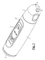
図1〜図3を参照すると、第1の実施形態の投光装置は、円筒状軽合金ケーシング1を備え、かつその中に収容されている。ケーシング1の前端は、透明なプラスチックディスク2によって閉鎖されるように封止されており、後端の上にはドーム状キャップ3がねじ込まれて、ケーシング1の閉鎖及び封止を完了している。
Referring to FIGS. 1 to 3, the light projecting device of the first embodiment includes a cylindrical light alloy casing 1 and is accommodated therein. The front end of the casing 1 is sealed so as to be closed by a transparent
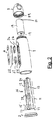
薄い金属パネル4が、ケーシング1の上面のくぼみ部分5内に位置し、装置内の2つの光源の動作の制御において手指で押下することができるパネル4の領域を示すように、しるしがエッチングされている。2つの光源は、図2〜図4に示すように、サブアセンブリ14における細長いシャシ13上にプリント回路基板(PCB)12とともに合わせて取り付けられる発光ダイオード(LED)10及びレーザー源モジュール11によって、それぞれ提供される。
The indicia is etched so that a
図4において組立分解形態で示すサブアセンブリ14では、LED10は、角度付きミラー15の真下においてシャシ13の上に支持されており、角度付きミラー15は、LED10からの光を正面の透明なディスク2を通して前方に反射し、可視光ビームを生成する役割を果たす。PCB12の真下においてシャシ13にレーザーモジュール11が取り付けられ、その投影開口部16から放出されるコヒーレントな光ビームを、像形成手段を介してディスク2を通して前方に向ける。像形成手段は、開口部16の上に固定されたポリカーボネートのディスク17の形態である回折光学素子(DOE)を備える。ディスク17は、光干渉により、開口部16からの光を回折させて、ディスク2を通って前方に投影される像にする。
In the
LED10及びレーザーモジュール11は、共通の電源、すなわち投光装置の後部に収
容されたバッテリ18から通電されるように、プリント回路基板12の個々の回路において接続されている。LED10用の通電回路は、バッテリ18の一方の極19から直列の基板12の個別の接点スイッチ20及びLED10を通って、ケーシング1及びキャップ3を介してバッテリ18の他方の極21に「戻る」ように延在している。同様に、レーザーモジュール11用の通電回路は、バッテリ18の極19から直列の基板12の個別の接点スイッチ22及びモジュール11を介して延在し、ケーシング1及びキャップ3を介して他方の極21に「戻る」。各スイッチ20及び22はボタン23を有し、ボタン23は、押下されると、繰返しの連続した3つの別個の状態、すなわち「オン」、「点滅」及び「オフ」を通して連続的にスイッチを順次切り替える。
The
スイッチ20が「オン」状態にある間、LED10の通電回路は、スイッチ20を通して直接閉じられ、それにより、LED10は連続的に光を放出し、一方、スイッチ20が「点滅」状態にある間、通電回路は、PCB12上の個々の点滅光回路(図示せず)を介してスイッチ20を通して完成される。点滅光回路は、断続的に(例えば、約3Hz〜4Hzのオン−オフ周波数で)回路を中断し、それにより、LED10によって点滅光のみが放出されるようにする。LED10の通電回路は、スイッチ20が「オフ」状態にあるときに開き、それにより、LED10によっていかなる光も放出されない。
While
スイッチ22の状態に応じて、レーザーモジュール11の同様の動作が発生する。つまり、スイッチ22が「オン」状態にあるとき、モジュール11は連続的に通電されてディスク17によって与えられる像の形態で光を放出し、一方、スイッチ22が「点滅」状態にあるとき、PCB12上の個々の点滅光回路(図示せず)が、スイッチ22によって通電回路内に含まれ、モジュール11によって放出される光が断続的に(例えば、約3Hz〜4Hzのオン−オフ周波数で)点滅するようにする。スイッチ22が「オフ」状態にあるとき、モジュール11の通電回路は、いかなる像も投影されないようにスイッチ22において遮断される。
Depending on the state of the
投光装置の組立中、サブアセンブリ14は、前端からケーシング1に入れられ、その後、スイッチ20及び22がくぼみ部分5(図2参照)内でケーシング1を通してそれぞれ開口部24及び25と位置合せして配置された状態で、ディスク2によって閉鎖される。開口部24及び25において、プラスチック材料の押しボタン26及び27が、それぞれスイッチ20及び22のボタン23と当接するように配置され、くぼみ部分5内のそれらの上に、ゴムシールプレート28が固定される。プレート28には、薄い金属パネル4が結合され、エッチングされたしるしが、手指による押下によって下にある押しボタン26又は27が関連するスイッチ20又は22のボタン23を作動させる位置に配置される。
During assembly of the floodlight device, the
好ましくはリチウムバッテリであるバッテリ18が、その極19がPCB12の通電回路と接触するように、ケーシング1内に挿入される。そして、キャップ3が、防水封止用の「O」リング29とともにケーシング1上にねじ込まれ、ケーシング1を介するバッテリ18の極21までの「戻り」経路を完成する。バッテリ18が充電式である状況では、ケーシング1及び/又はキャップ3を通しての接点接触部(図示せず)により充電を可能にすることができる。
A
ケーシング1の下側のねじ穴30により、後により詳細に説明するように、投光装置の、自転車(又は他の車両)の好適な取付台への取り付けが容易になる。安全のために、望ましくは、投光装置がその取付台に完全に設置されない限りかつ設置されるまで、レーザーモジュール11に通電することができないことが確実にされる。例えばこれに関して、取付台は、希土類磁石等の磁性部材を組み込むことができ、それにより、投光装置は、レーザーモジュール11の通電回路に接続されたホール効果素子又はリードスイッチ等、磁気スイッチ素子を含むことができる。磁気スイッチ素子の目的は、PCB12と通信して
、装置が取付台に完全に設置された場合にのみ、スイッチ22が「オン」又は「点滅」状態にあるときに磁石の影響下でその回路を完成させるが、そうでない場合は、スイッチ22の状態とは無関係にその回路を開いたままに保持する、ということである。
The
投光装置が自転車(又は他の車両)におけるその取付台に完全に設置されると、スイッチ20をその「オン」又は「点滅」状態に作動させるような制御パネル4の手指操作により、LED10からの光が車両の前方の道を照明する。スイッチ22の対応する作動により、レーザーモジュール11が通電されて、ディスク17の干渉パターンによって決まる像をその道に投影させる。各場合に放出される光は、スイッチ選択が「オン」状態であるか「点滅」状態であるかに応じて、連続するか、又は点滅することになる。
When the floodlight device is fully installed on its mount in a bicycle (or other vehicle), the
コード又は鎖を、キャップ3の穴31に通すことによって投光装置に取り付けることができる。
The cord or chain can be attached to the floodlight by passing it through the hole 31 of the
本発明の装置の例示的なスイッチング回路の図を、図5に概略的に示す。ここでは、磁気スイッチ素子が、出力信号「Out」を照明電圧Vccと接地「GND」との間で切り替えるように動作可能であることを見ることができる。 A diagram of an exemplary switching circuit of the device of the present invention is shown schematically in FIG. Here it can be seen that the magnetic switching element is operable to switch the output signal “Out” between the illumination voltage Vcc and the ground “GND”.
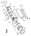
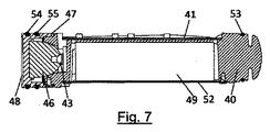
本発明の更なる実施形態を図6、図7及び図8に示す。図6は、装置の内部コンポーネントの組立分解斜視図を概略的に示し、図7は、図6のコンポーネントの概略断面図であり、図8は、図7に類似しているが更にケーシングを示している。 A further embodiment of the present invention is shown in FIGS. FIG. 6 schematically shows an exploded perspective view of the internal components of the device, FIG. 7 is a schematic cross-sectional view of the components of FIG. 6, and FIG. 8 is similar to FIG. ing.
ここで、図8に示すように、第1の実施形態のケーシング1に概して類似するケーシング56が、図6及び図7に示す内部コンポーネントを収容するために使用される。ここで、変更形態のシャシ40が使用され、それは、例えばダイカスト鋳造することができ、その形状は、ケーシング56の内面の形状に実質的に一致する。シャシ40はPCB41を支持し、PCB41の上に、レーザーユニット42及びLED光源43用のそれぞれの通電回路が少なくとも部分的に設けられている。第1の実施形態と同様に、PCB41は、レーザー及びLED用のそれぞれの接点スイッチ(図示せず)を支持し、それらは、例えば第1の実施形態のような薄い金属プレートを介して、ケーシング56の対応する領域を押すことによって動作可能である。
Here, as shown in FIG. 8, a
レーザーユニット42が、シャシ40の後部に設けられた開口部内に取り付けられ、一方で、LED源43及び関連する反射体46、例えば放物線反射体が、シャシ40の前端に受けられることを見ることができる。チャネル44が、シャシの長さを通して、半径中心からずれて、正面から背面まで延在し、レーザーユニットの取付開口部を接続し、ユニットからのレーザー光がシャシを通過して正面まで進むのを可能にする。DOE45がチャネル44の正面部分に保持されて、第1の実施形態と同様に像を生成する。反射体46及びLED源43は、端部キャップ47によってシャシ40内の適所に保持される。端部キャップ47は、その端部に透明なディスク48を備え、LED源43からの光及びユニット42からのレーザー光の両方がそこを通過するのを可能にする。
It can be seen that the
シャシ40の下側はバッテリモジュールを支持し、バッテリモジュールは、バッテリ49、例えばリチウム−イオン電池を備え、バッテリ49の上方及び下方にはそれぞれ関連する絶縁ライナー50及び51が設けられている。バッテリは、保持プレート52によってシャシ40内に保持され、保持プレート52は、使用時にシャシ40に固定して取り付けられ、それらの間にバッテリ及び絶縁ライナーを保持する。
The lower side of the
シャシ40の後端にOリング53が設けられており、端部キャップ47もまた軸方向に変位したOリング54及び55を支持し、それによりケーシング56内の水密嵌合を確実
にする。
An O-
図9〜図12は、この第2の実施形態の装置用の取付機構を概略的に示す。しかしながら、例示の目的で、取り付けはこの第2の実施形態に関連して記載されているが、必要な変更が最小限で、第1の実施形態の装置で非常に類似する取付機構を使用することができることが直ちに留意されるべきである。 9 to 12 schematically show an attachment mechanism for the apparatus of the second embodiment. However, for illustrative purposes, the attachment has been described in connection with this second embodiment, but uses a very similar attachment mechanism in the device of the first embodiment with minimal changes required. It should be noted immediately that it can.
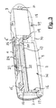
図9は、投光ユニットを概略的に示す。投光ユニットは、取付台60に取り付けられたそのケーシング56内にある。取付台60は、取付台を自転車に取り付けるための取付手段を含み、この取付手段は、略円形経路に沿って弓状に伸びる突出ブラケット61を含み、ブラケット61は、その先端部においてピボット63を介してアーム62に枢動可能に接続されており、アーム62は、実質的にブラケット61と同じ曲率半径の弧として形成されている。この構成は、閉鎖形態にあるとき、ブラケット61及びアーム62の内面が自転車のハンドルバー79を受ける閉鎖した円を実質的に画定するようなものである。ブラケット61及びアーム62の内面は、可撓性ゴムスペーサー73によって覆われ、ハンドルバーに強化グリップを提供する。スペーサー73は、必要な場合に、延長位置まで付勢されてアーム62の開放に役立つ。アーム62の先端部は、ボルト65のシャフトを受けるように実質的に「C」字型ジョー64を含み、ボルト65は、取付台60の本体内にねじ嵌合によって受けられ、使用時にそこから下方に延在する。取付台60をハンドルバー(図示せず)に取り付けるために、アーム62は枢動して開放され、ジョー64がボルト65のシャフトを受けるように、ブラケット61及びアーム62がハンドルバーの周囲で閉鎖され、ボルト65は、取付台60にねじ込むことによって締められ、必要に応じてハンドルバーを締め付け、ボルト65の頭部が、ジョー64の下側に対して押圧される。或る範囲の直径のハンドルバーに適応するために、1つ又は複数の追加の可撓性ゴムスペーサー(図示せず)を、アーム/ブラケットとハンドルバーとの間に、締め付ける前に挿入することができる。取付台を取り除くためには、プロセスが反対に行われる。決してボルト65を取付台60から完全に取り除く必要はなく、単に、ジョー64がその頭部を通過するのを可能にするように十分後退させるだけでよいことが留意されるべきである。
FIG. 9 schematically shows the light projecting unit. The light projecting unit is in its
取付台60は、モジュール式であり、別個の差込口、すなわち、使用時に装置アダプター67のステム66(図10参照)を受ける垂直軸開口部を有するブラケットカップ70を含み、装置アダプター67は、投光ユニットケーシング56の下側に半永久的に取り付けられている。アダプター67は、タブ80を支持する突出板ばねレバー68を含む。タブ80は、取付台本体に接続されると、ブラケットカップ70の外周部に延在する突出リップ69と係合して、それらの間の相対的な垂直移動を防止する。この係合を、レバー68を手動で持ち上げてリップ69から離れてケーシング56及びタブ80に向かって移動させ、それによりステム66を上方にかつカップ70から出るように摺動させることができるようにすることによって、解除することができる。カップ70は、図11により詳細に示すボルト71によって取付台本体に対して係止可能である。
The mounting 60 is modular and includes a
図10は、図9の取付機構を概略的に示すが、部分的に分解された状態で、レバー68が引き上げられ、アダプター67がカップ70から取り除かれている。ここでは、ステム66は円形断面ではなく非対称多角形断面であり、カップ70の開口部は対応して形成されていることを見ることができる。これは、第1に、ステム66を1つの向きで開口部内に受けることしかできないことを意味し、第2に、一旦受けられると、開口部に対して回転することができないことを意味する。
FIG. 10 schematically shows the attachment mechanism of FIG. 9, with the
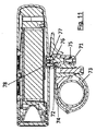
図11は、図9の取付機構の断面図を概略的に示す。なお、ここでは、取付台は、相対的に直径の小さいハンドルバーに合わせるように締められている。まず、取付台本体は、ゴムスペーサー73の対応する栓を受けかつ保持するためのソケット74を含むことを見
ることができる。カップ70は、その上端に近接して、希土類磁石72等の磁性部材を含む。カップ70は、その下端にボルト71を受ける。ボルト71の頭部とカップ70との間に、取付台本体のフランジ75があり、それにより、ボルト71をカップ内に締め付けることにより、カップが本体に固定して係止される。アダプター67が、2つのボルト76、77によってケーシング56に取り付けられ、ボルト76、77は、アダプター67及びケーシング56の相対的な回転を防止する。ボルト76、77は、金属製である場合、磁束を磁石72からケーシング56に向けるのにも役立つ。レーザーユニット42用の通電回路の一部を形成するホール効果センサー又はリードスイッチ(図示せず)等の磁気スイッチ素子を含む、小型のプリント印刷基板78が、使用時にボルト76に隣接して、ケーシング56の下側に近接して位置し、それにより、アダプターがカップ70内に正しく受けられた場合にのみ、磁石72からの磁束の影響を受ける。
FIG. 11 schematically shows a cross-sectional view of the attachment mechanism of FIG. Here, the mounting base is fastened so as to fit the handlebar having a relatively small diameter. First, it can be seen that the mount body includes a
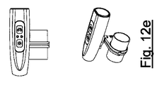
カップ70は、取付台本体に対して相対的に回転可能であり、それにより、投光装置の左右方向を、レバー68の、取付台本体又はハンドルバーとの当接によって境界が定められる範囲内で無限に調整することができる。このように、幾つかの角度位置、特に投光ユニットが後方に面する角度位置が防止されて、明確に望ましくないか又は危険な位置(ユニットが後方を向き、LED又はレーザー光を自転車に乗っている人に当てる等)が使用されることを回避する。これを、図12a〜図12eに概略的に示し、図12a〜図12eは、ハンドルバー79に対する5つの異なるあり得る角度位置にある装置を示す。いずれの角度位置が用いられても、ボルト76は、カップ及びケーシングが一緒に移動しているため、磁気スイッチ素子に近接したままになることが留意されるべきである。
The
使用時、最初に、取付台は上記で概説したようにハンドルバーに締め付けられる。ブラケットカップ70が取付台本体に配置され、ステム66がその中に受けられかつ係合する。投光ユニットの左右位置決めは、要求通りになるまで調整され、その後、ユニットは、ボルト71を締め付けることによってその位置で保持され、カップ70を取付台本体に対して固定して保持する。
In use, first the mount is tightened to the handlebar as outlined above. A
上述した実施形態は単に例示的なものであり、本発明の範囲内にある他の可能性及び代替物は、当業者に明らかとなろう。例えば、LED及びレーザーユニットの各々に別個の電源を設けることができる。 The above-described embodiments are merely exemplary, and other possibilities and alternatives within the scope of the invention will be apparent to those skilled in the art. For example, a separate power source can be provided for each LED and laser unit.
ボルト76は、磁束をホール効果センサーに集束させるものとして示されているが、他の技法、例えば他の磁束誘導コンポーネントを使用することもできるし、センサーを、単に使用時に磁石により近接する位置で維持し、それに従って磁石の強度を選択することもできる。
Although the
Claims (29)
レーザーユニット及び光源を備え、
前記レーザーユニットは、レーザー源と、該レーザー源によって生成されるレーザー光に対して作用し、使用時に前記車両の外部にある面に所定の像を投影させるように構成された像形成手段とを備え、
前記光源は、使用時に可視光ビームを生成する、車両で使用する投光装置。 A light projecting device for use in a vehicle, the light projecting device comprising:
A laser unit and a light source,
The laser unit includes a laser source and image forming means configured to act on the laser light generated by the laser source and project a predetermined image on a surface outside the vehicle when in use. Prepared,
The light source is a light projecting device for use in a vehicle that generates a visible light beam when in use.
前記投光装置は、発光手段と、該発光手段用の電源と、該発光手段と該電源との間に接続された磁気スイッチ素子とを備える投光ユニットを備え、
該取付台は、該取付台を前記自転車に取り付ける取付手段と、前記投光ユニットを脱着可能に受ける受け手段とを備え、
該取付台は、磁性部材を更に備え、それにより、前記投光ユニットが該取付台によって受けられると、前記磁気スイッチ素子が、前記磁性部材の磁気的影響を受けるようになり、前記電源から前記発光手段まで電流が流れるのを可能にする、自転車に投光装置を取り付ける取付台。 A mounting base for mounting a floodlight device on a bicycle,
The light projecting device includes a light projecting unit including a light emitting unit, a power source for the light emitting unit, and a magnetic switch element connected between the light emitting unit and the power source,
The mounting base includes mounting means for mounting the mounting base on the bicycle, and receiving means for receiving the light projecting unit in a detachable manner.
The mounting base further includes a magnetic member, whereby when the light projecting unit is received by the mounting base, the magnetic switch element is affected by the magnetic member, and the power source A mounting base that attaches a light projector to a bicycle that allows current to flow to the light emitting means.
発光手段と該発光手段用の電源とを備える投光ユニットと、
取付台であって、該取付台を前記自転車に取り付ける取付手段と、前記投光ユニットを脱着可能に受ける受け手段とを備える取付台と、
を備え、
前記取付台は磁性部材を更に備え、前記投光ユニットは前記発光手段と前記電源との間に接続された磁気スイッチ素子を備え、該磁気スイッチ素子は、前記投光ユニットが前記取付台に受けられ、該磁気スイッチ素子が前記磁性部材の磁気的影響を受けているとき、前記電源から前記発光手段に電流が流れるのを可能にするが、前記投光ユニットが前記取付台から取り外されているとき、前記電流の流れを阻止する、自転車で使用する投光装置。 A floodlight device for use on a bicycle, the floodlight device comprising:
A light projecting unit comprising a light emitting means and a power source for the light emitting means;
A mounting base comprising: mounting means for mounting the mounting base on the bicycle; and receiving means for detachably receiving the light projecting unit;
With
The mounting base further includes a magnetic member, the light projecting unit includes a magnetic switch element connected between the light emitting means and the power source, and the magnetic switch element is received by the light projecting unit on the mounting base. And allowing the current to flow from the power source to the light emitting means when the magnetic switch element is magnetically affected by the magnetic member, but the light projecting unit is removed from the mounting base. When the light projecting device used in a bicycle, the current flow is blocked.
発光手段と該発光手段用の電源とを備える投光ユニットと、
取付台であって、該取付台を前記自転車に取り付ける取付手段と、前記投光ユニットを脱着可能に受ける受け手段とを備える取付台と、
を備え、
前記受け手段は、該受け手段に対する或る範囲の角度位置の範囲内で前記投光ユニットを受けるようになっており、それにより、該投光装置から投影される光の方向を、前記自転車に対して選択することができ、前記受け手段は、選択された角度位置で前記投光ユニットを係止する固定手段を更に備える、自転車で使用する投光装置。 A floodlight device for use on a bicycle, the floodlight device comprising:
A light projecting unit comprising a light emitting means and a power source for the light emitting means;
A mounting base comprising: mounting means for mounting the mounting base on the bicycle; and receiving means for detachably receiving the light projecting unit;
With
The receiving means is adapted to receive the light projecting unit within a range of angular positions with respect to the receiving means, whereby the direction of light projected from the light projecting device is directed to the bicycle. A light projecting device for use on a bicycle, wherein the light receiving device further comprises fixing means for locking the light projecting unit at a selected angular position.
前記取付台から取り外されているとき、前記電流の流れを阻止する、請求項23に記載の投光装置。 The mounting base further includes a magnetic member, the light projecting unit includes a magnetic switching element connected between the light emitting means and the power source, and the magnetic switching element is received by the light projecting unit by the mounting base. And allowing the current to flow from the power source to the light emitting means when the magnetic switch element is magnetically affected by the magnetic member, but the light projecting unit is removed from the mounting base. 24. The light projecting device according to claim 23, wherein the current flow is blocked.
Applications Claiming Priority (3)
| Application Number | Priority Date | Filing Date | Title |
|---|---|---|---|
| GBGB1220965.6A GB201220965D0 (en) | 2012-11-21 | 2012-11-21 | Light-projecting devices |
| GB1220965.6 | 2012-11-21 | ||
| PCT/GB2013/052394 WO2014080168A1 (en) | 2012-11-21 | 2013-09-12 | Bicycle light-projecting devices with laser beam |
Publications (2)
| Publication Number | Publication Date |
|---|---|
| JP2016503366A true JP2016503366A (en) | 2016-02-04 |
| JP2016503366A5 JP2016503366A5 (en) | 2016-10-13 |
Family
ID=47521521
Family Applications (1)
| Application Number | Title | Priority Date | Filing Date |
|---|---|---|---|
| JP2015543513A Pending JP2016503366A (en) | 2012-11-21 | 2013-09-12 | Bicycle projector with laser beam |
Country Status (9)
| Country | Link |
|---|---|
| US (1) | US20150274231A1 (en) |
| EP (1) | EP2922744B1 (en) |
| JP (1) | JP2016503366A (en) |
| CN (1) | CN105246772A (en) |
| AU (2) | AU2013349430A1 (en) |
| CA (1) | CA2897423A1 (en) |
| GB (1) | GB201220965D0 (en) |
| HK (1) | HK1215415A1 (en) |
| WO (1) | WO2014080168A1 (en) |
Families Citing this family (6)
| Publication number | Priority date | Publication date | Assignee | Title |
|---|---|---|---|---|
| GB2529613B (en) | 2014-07-03 | 2020-05-20 | Smidsy Ltd | Vehicle mounted laser projector |
| GB2542117B (en) * | 2015-09-04 | 2022-04-06 | Smidsy Ltd | Laser projection device |
| CN105487228A (en) * | 2015-11-24 | 2016-04-13 | 小米科技有限责任公司 | Bicycle computer data display method and device |
| ES1160036Y (en) * | 2016-06-16 | 2017-01-24 | Netun Solutions S L | EMERGENCY MOBILE LIGHT DEVICE |
| US10392068B2 (en) | 2017-08-25 | 2019-08-27 | Daniel Ebrahemi | Handlebar lights with turn actuator for a bicycle |
| US11530788B2 (en) * | 2021-02-03 | 2022-12-20 | Brightz, ltd. | Sound and illumination device for bicycles |
Citations (8)
| Publication number | Priority date | Publication date | Assignee | Title |
|---|---|---|---|---|
| JPS6022541A (en) * | 1983-07-19 | 1985-02-05 | Honda Motor Co Ltd | Lighting apparatus for small-sized car |
| JPH07130202A (en) * | 1993-11-01 | 1995-05-19 | Fumio Ebina | Method and device for automatically lighting flashlight in earthquake or other disaster |
| JP2004243794A (en) * | 2003-02-10 | 2004-09-02 | Toyota Motor Corp | Safety support device for vehicle |
| JP2005306337A (en) * | 2004-04-26 | 2005-11-04 | Denso Corp | Information display device for mobile body |
| US20100283590A1 (en) * | 2009-05-08 | 2010-11-11 | Alexander Kirby Tee | Safety light device |
| WO2012067657A1 (en) * | 2010-11-17 | 2012-05-24 | Light & Motion Industries | Underwater lights for divers |
| US20120285026A1 (en) * | 2009-12-28 | 2012-11-15 | Byung Dan Min | Apparatus for marking guideline for transportation vehicle |
| JP2012254700A (en) * | 2011-06-08 | 2012-12-27 | Bridgestone Cycle Co | Functional component mounting structure, and motorcycle |
Family Cites Families (36)
| Publication number | Priority date | Publication date | Assignee | Title |
|---|---|---|---|---|
| US4803605A (en) | 1987-08-04 | 1989-02-07 | Rayovac Corporation | Flashlight with a backup system |
| US5690410A (en) | 1995-10-23 | 1997-11-25 | Lin; Tzu-Lung | Light device for a bicycle |
| US6008941A (en) | 1996-06-25 | 1999-12-28 | Digital Optics Corporation | Optical soft aperture and use thereof |
| US6007219A (en) | 1997-12-17 | 1999-12-28 | O'meara; James C. | Laser lighting system |
| US5909062A (en) | 1998-03-10 | 1999-06-01 | Krietzman; Mark Howard | Secondary power supply for use with handheld illumination devices |
| US6057657A (en) | 1998-07-02 | 2000-05-02 | Shimano, Inc. | Magnetically operated bicycle antitheft device |
| US20030227773A1 (en) | 2002-06-05 | 2003-12-11 | Yang Chang Yao | Light device for attaching onto various objects |
| EP1410982B1 (en) | 2002-10-18 | 2008-05-07 | Shimano Inc. | Bicycle lighting equipment |
| JP3768964B2 (en) * | 2003-01-22 | 2006-04-19 | 秀仁 下岡 | Wheel light emitting device for motorcycles |
| US7652757B2 (en) * | 2004-01-09 | 2010-01-26 | Securency International Pty Ltd | Method and apparatus for inspection of security articles incorporating a diffractive optical projection element |
| WO2005094526A2 (en) * | 2004-03-24 | 2005-10-13 | Corium International, Inc. | Transdermal delivery device |
| FR2870201B3 (en) | 2004-05-13 | 2006-05-05 | Richard Hsu | BRAKE WARNING DEVICE FOR BICYCLE |
| KR100694072B1 (en) * | 2004-12-15 | 2007-03-12 | 삼성전자주식회사 | Illumination system eliminating laser speckle and projection system employing the same |
| JP4548724B2 (en) * | 2005-02-22 | 2010-09-22 | 本田技研工業株式会社 | Electrical component arrangement structure |
| US7397355B2 (en) | 2005-05-14 | 2008-07-08 | Randy Lee Tracy | Reversibly mountable acceleration/de-acceleration warning light |
| WO2007089253A2 (en) * | 2005-06-01 | 2007-08-09 | Bae Systems Information And Electronic Systems Integration Inc. | Method and apparatus for protecting vehicles and personnel against incoming projectiles |
| US7192172B1 (en) | 2005-09-08 | 2007-03-20 | K.W. Muth Company, Inc. | Visual warning device |
| CN1932371A (en) | 2005-09-14 | 2007-03-21 | 洪宝川 | Two-purpose chargeable lamp set with power supply function |
| US20070084496A1 (en) * | 2005-10-18 | 2007-04-19 | Edey Bruce A | Solid state power supply and cooling apparatus for a light vehicle |
| WO2007079549A1 (en) * | 2006-01-16 | 2007-07-19 | Securency International Pty Ltd | Data storage in a diffractive optical element |
| JP2007238063A (en) * | 2006-03-06 | 2007-09-20 | Aiko Masataka | Fluorescent mark for tire |
| KR100832623B1 (en) * | 2006-03-30 | 2008-05-27 | 삼성전기주식회사 | Display system using one panel optical modulator |
| WO2007124536A1 (en) * | 2006-04-27 | 2007-11-08 | Colin Dunlop | A light source apparatus |
| TW200903954A (en) * | 2007-07-04 | 2009-01-16 | Acxing Ind Co Ltd | Lighting device for vehicles |
| CN101591994B (en) * | 2008-05-28 | 2012-06-27 | 罗士夫 | Micro power-consumption passive electronic locking head |
| US8087797B2 (en) | 2008-07-18 | 2012-01-03 | Stanley Black & Decker, Inc. | Illumination device with detachable light sources |
| EP2194722A1 (en) * | 2008-12-05 | 2010-06-09 | Sony Corporation | Laser projection device and method for manufacturing a laser projection device |
| JP5657561B2 (en) * | 2008-12-09 | 2015-01-21 | デルファイ・テクノロジーズ・インコーポレーテッド | Diffraction combiner for multi-color display and monochrome display, manufacturing method thereof, and head-up display device using the same |
| US20100253919A1 (en) | 2009-02-13 | 2010-10-07 | Ralph Paul Douglas | Method and system for laser projection and holographic diffraction grating for a vehicle |
| FR2949104B1 (en) | 2009-08-13 | 2016-02-26 | Vincent Remy | SIGNALING DEVICE FOR CYCLISTS OR CYCLOMOTORISTS |
| GB2474486B (en) | 2009-10-16 | 2014-05-07 | Salamander 3D Ltd | A portable safety light |
| EP2534528B1 (en) | 2010-02-10 | 2024-01-03 | Signify Holding B.V. | Lighting apparatus |
| CN201800817U (en) | 2010-07-28 | 2011-04-20 | 南京信息职业技术学院 | Battery jar burglarproof alarm device for electric bicycle |
| US10604203B2 (en) * | 2010-10-12 | 2020-03-31 | Weng-Dah Ken | Green bike |
| KR101184409B1 (en) * | 2010-11-04 | 2012-09-20 | 김세연 | Taillight for Bicycle and Method for thereof |
| GB2490889B (en) | 2011-05-16 | 2013-04-17 | Emily Sophie Brooke | Light projection safety device for a two wheeled vehicle |
-
2012
- 2012-11-21 GB GBGB1220965.6A patent/GB201220965D0/en not_active Ceased
-
2013
- 2013-09-12 JP JP2015543513A patent/JP2016503366A/en active Pending
- 2013-09-12 CN CN201380060170.2A patent/CN105246772A/en active Pending
- 2013-09-12 WO PCT/GB2013/052394 patent/WO2014080168A1/en active Application Filing
- 2013-09-12 EP EP13776845.3A patent/EP2922744B1/en not_active Revoked
- 2013-09-12 CA CA2897423A patent/CA2897423A1/en not_active Abandoned
- 2013-09-12 US US14/443,442 patent/US20150274231A1/en not_active Abandoned
- 2013-09-12 AU AU2013349430A patent/AU2013349430A1/en not_active Abandoned
-
2016
- 2016-03-23 HK HK16103445.7A patent/HK1215415A1/en unknown
-
2017
- 2017-10-09 AU AU2017245273A patent/AU2017245273A1/en not_active Abandoned
Patent Citations (8)
| Publication number | Priority date | Publication date | Assignee | Title |
|---|---|---|---|---|
| JPS6022541A (en) * | 1983-07-19 | 1985-02-05 | Honda Motor Co Ltd | Lighting apparatus for small-sized car |
| JPH07130202A (en) * | 1993-11-01 | 1995-05-19 | Fumio Ebina | Method and device for automatically lighting flashlight in earthquake or other disaster |
| JP2004243794A (en) * | 2003-02-10 | 2004-09-02 | Toyota Motor Corp | Safety support device for vehicle |
| JP2005306337A (en) * | 2004-04-26 | 2005-11-04 | Denso Corp | Information display device for mobile body |
| US20100283590A1 (en) * | 2009-05-08 | 2010-11-11 | Alexander Kirby Tee | Safety light device |
| US20120285026A1 (en) * | 2009-12-28 | 2012-11-15 | Byung Dan Min | Apparatus for marking guideline for transportation vehicle |
| WO2012067657A1 (en) * | 2010-11-17 | 2012-05-24 | Light & Motion Industries | Underwater lights for divers |
| JP2012254700A (en) * | 2011-06-08 | 2012-12-27 | Bridgestone Cycle Co | Functional component mounting structure, and motorcycle |
Also Published As
| Publication number | Publication date |
|---|---|
| WO2014080168A1 (en) | 2014-05-30 |
| EP2922744A1 (en) | 2015-09-30 |
| AU2017245273A1 (en) | 2017-11-02 |
| EP2922744B1 (en) | 2019-06-19 |
| CA2897423A1 (en) | 2014-05-30 |
| US20150274231A1 (en) | 2015-10-01 |
| GB201220965D0 (en) | 2013-01-02 |
| AU2013349430A1 (en) | 2015-05-28 |
| HK1215415A1 (en) | 2016-08-26 |
| CN105246772A (en) | 2016-01-13 |
Similar Documents
| Publication | Publication Date | Title |
|---|---|---|
| JP2016503366A (en) | Bicycle projector with laser beam | |
| JP3152474U (en) | Bicycle light device | |
| US7745957B2 (en) | Combination task lamp and flash light | |
| US7402961B2 (en) | Circuit for illuminating multiple light emitting devices | |
| US7363873B2 (en) | Bicycle shift control device with light structure | |
| EP2662270A2 (en) | Bicycle light | |
| CA2739456A1 (en) | Flashlight and illuminated rear section with two-sided lighting module | |
| JP2005056708A (en) | Lighting apparatus | |
| US20130141933A1 (en) | Pivotable led lighting apparatus and universal mounting assembly and method | |
| US7549770B2 (en) | Module for a flashlight or lantern | |
| JP3109661U (en) | flashlight | |
| TW201527165A (en) | Bicycle taillight with parallel lighting element | |
| KR20170002200A (en) | Breathable gaiters secured | |
| KR101618860B1 (en) | LED lamp for alarm | |
| JP2006044321A (en) | Front light device of motorcycle | |
| JP3162062U (en) | Bicycle lock | |
| KR101252246B1 (en) | Turn signal and safety lamp of cycle | |
| GB2205391A (en) | A lamp for a bicycle or motorcycle | |
| JP3162754U (en) | Rear view mirror | |
| BE1017373A6 (en) | Spoke lighting is for bicycle, wehel of which has rim spokes and nave, with lighting device on spokes, whilst energy production device is in nave | |
| BE1016557A3 (en) | Lighting for a bike like a bike. | |
| US11530788B2 (en) | Sound and illumination device for bicycles | |
| NZ567218A (en) | A bicycle safety device | |
| JP3146764U (en) | Bicycle warning light | |
| GB2589579A (en) | A cycle safety integrated light and anti-theft device |
Legal Events
| Date | Code | Title | Description |
|---|---|---|---|
| A521 | Request for written amendment filed |
Free format text: JAPANESE INTERMEDIATE CODE: A523 Effective date: 20160825 |
|
| A621 | Written request for application examination |
Free format text: JAPANESE INTERMEDIATE CODE: A621 Effective date: 20160825 |
|
| A977 | Report on retrieval |
Free format text: JAPANESE INTERMEDIATE CODE: A971007 Effective date: 20170413 |
|
| A131 | Notification of reasons for refusal |
Free format text: JAPANESE INTERMEDIATE CODE: A131 Effective date: 20170419 |
|
| A601 | Written request for extension of time |
Free format text: JAPANESE INTERMEDIATE CODE: A601 Effective date: 20170707 |
|
| A601 | Written request for extension of time |
Free format text: JAPANESE INTERMEDIATE CODE: A601 Effective date: 20170913 |
|
| A521 | Request for written amendment filed |
Free format text: JAPANESE INTERMEDIATE CODE: A523 Effective date: 20171016 |
|
| A02 | Decision of refusal |
Free format text: JAPANESE INTERMEDIATE CODE: A02 Effective date: 20180314 |