JP2016502044A - Universal locking clip - Google Patents
Universal locking clip Download PDFInfo
- Publication number
- JP2016502044A JP2016502044A JP2015545803A JP2015545803A JP2016502044A JP 2016502044 A JP2016502044 A JP 2016502044A JP 2015545803 A JP2015545803 A JP 2015545803A JP 2015545803 A JP2015545803 A JP 2015545803A JP 2016502044 A JP2016502044 A JP 2016502044A
- Authority
- JP
- Japan
- Prior art keywords
- tongue
- clip
- bridge
- segment
- base
- Prior art date
- Legal status (The legal status is an assumption and is not a legal conclusion. Google has not performed a legal analysis and makes no representation as to the accuracy of the status listed.)
- Pending
Links
- 239000013077 target material Substances 0.000 claims description 37
- 238000000034 method Methods 0.000 claims description 27
- 210000005182 tip of the tongue Anatomy 0.000 claims description 4
- 230000014759 maintenance of location Effects 0.000 abstract description 10
- 239000000463 material Substances 0.000 description 14
- 239000000853 adhesive Substances 0.000 description 4
- 230000001070 adhesive effect Effects 0.000 description 4
- 239000004677 Nylon Substances 0.000 description 3
- 210000003484 anatomy Anatomy 0.000 description 3
- 230000008901 benefit Effects 0.000 description 3
- 239000004744 fabric Substances 0.000 description 3
- 230000003993 interaction Effects 0.000 description 3
- 239000002184 metal Substances 0.000 description 3
- 230000004048 modification Effects 0.000 description 3
- 238000012986 modification Methods 0.000 description 3
- 229920001778 nylon Polymers 0.000 description 3
- 238000004804 winding Methods 0.000 description 3
- 239000004820 Pressure-sensitive adhesive Substances 0.000 description 2
- 206010052428 Wound Diseases 0.000 description 2
- 208000027418 Wounds and injury Diseases 0.000 description 2
- 239000006260 foam Substances 0.000 description 2
- 230000007246 mechanism Effects 0.000 description 2
- 239000004033 plastic Substances 0.000 description 2
- 229920003023 plastic Polymers 0.000 description 2
- NIXOWILDQLNWCW-UHFFFAOYSA-M Acrylate Chemical compound [O-]C(=O)C=C NIXOWILDQLNWCW-UHFFFAOYSA-M 0.000 description 1
- 229920000742 Cotton Polymers 0.000 description 1
- JOYRKODLDBILNP-UHFFFAOYSA-N Ethyl urethane Chemical compound CCOC(N)=O JOYRKODLDBILNP-UHFFFAOYSA-N 0.000 description 1
- 244000043261 Hevea brasiliensis Species 0.000 description 1
- CERQOIWHTDAKMF-UHFFFAOYSA-N Methacrylic acid Chemical compound CC(=C)C(O)=O CERQOIWHTDAKMF-UHFFFAOYSA-N 0.000 description 1
- 240000007643 Phytolacca americana Species 0.000 description 1
- 239000004743 Polypropylene Substances 0.000 description 1
- 238000004026 adhesive bonding Methods 0.000 description 1
- 230000004075 alteration Effects 0.000 description 1
- 238000004873 anchoring Methods 0.000 description 1
- 238000013459 approach Methods 0.000 description 1
- 230000006835 compression Effects 0.000 description 1
- 238000007906 compression Methods 0.000 description 1
- 230000000994 depressogenic effect Effects 0.000 description 1
- 239000013013 elastic material Substances 0.000 description 1
- 229920001971 elastomer Polymers 0.000 description 1
- 239000000499 gel Substances 0.000 description 1
- 230000003100 immobilizing effect Effects 0.000 description 1
- 230000006872 improvement Effects 0.000 description 1
- 238000004519 manufacturing process Methods 0.000 description 1
- 229920003052 natural elastomer Polymers 0.000 description 1
- 229920001194 natural rubber Polymers 0.000 description 1
- 229920013639 polyalphaolefin Polymers 0.000 description 1
- 229920000515 polycarbonate Polymers 0.000 description 1
- 239000004417 polycarbonate Substances 0.000 description 1
- 229920000728 polyester Polymers 0.000 description 1
- 229920000379 polypropylene carbonate Polymers 0.000 description 1
- 229920001296 polysiloxane Polymers 0.000 description 1
- 229920002635 polyurethane Polymers 0.000 description 1
- 239000004814 polyurethane Substances 0.000 description 1
- 230000000717 retained effect Effects 0.000 description 1
- 239000005060 rubber Substances 0.000 description 1
- 229920006132 styrene block copolymer Polymers 0.000 description 1
- 229920003051 synthetic elastomer Polymers 0.000 description 1
- 239000005061 synthetic rubber Substances 0.000 description 1
- 238000003466 welding Methods 0.000 description 1
Images


Classifications
-
- A—HUMAN NECESSITIES
- A61—MEDICAL OR VETERINARY SCIENCE; HYGIENE
- A61F—FILTERS IMPLANTABLE INTO BLOOD VESSELS; PROSTHESES; DEVICES PROVIDING PATENCY TO, OR PREVENTING COLLAPSING OF, TUBULAR STRUCTURES OF THE BODY, e.g. STENTS; ORTHOPAEDIC, NURSING OR CONTRACEPTIVE DEVICES; FOMENTATION; TREATMENT OR PROTECTION OF EYES OR EARS; BANDAGES, DRESSINGS OR ABSORBENT PADS; FIRST-AID KITS
- A61F15/00—Auxiliary appliances for wound dressings; Dispensing containers for dressings or bandages
- A61F15/006—Bandage fasteners
-
- F—MECHANICAL ENGINEERING; LIGHTING; HEATING; WEAPONS; BLASTING
- F16—ENGINEERING ELEMENTS AND UNITS; GENERAL MEASURES FOR PRODUCING AND MAINTAINING EFFECTIVE FUNCTIONING OF MACHINES OR INSTALLATIONS; THERMAL INSULATION IN GENERAL
- F16B—DEVICES FOR FASTENING OR SECURING CONSTRUCTIONAL ELEMENTS OR MACHINE PARTS TOGETHER, e.g. NAILS, BOLTS, CIRCLIPS, CLAMPS, CLIPS OR WEDGES; JOINTS OR JOINTING
- F16B2/00—Friction-grip releasable fastenings
- F16B2/20—Clips, i.e. with gripping action effected solely by the inherent resistance to deformation of the material of the fastening
- F16B2/22—Clips, i.e. with gripping action effected solely by the inherent resistance to deformation of the material of the fastening of resilient material, e.g. rubbery material
-
- Y—GENERAL TAGGING OF NEW TECHNOLOGICAL DEVELOPMENTS; GENERAL TAGGING OF CROSS-SECTIONAL TECHNOLOGIES SPANNING OVER SEVERAL SECTIONS OF THE IPC; TECHNICAL SUBJECTS COVERED BY FORMER USPC CROSS-REFERENCE ART COLLECTIONS [XRACs] AND DIGESTS
- Y10—TECHNICAL SUBJECTS COVERED BY FORMER USPC
- Y10T—TECHNICAL SUBJECTS COVERED BY FORMER US CLASSIFICATION
- Y10T24/00—Buckles, buttons, clasps, etc.
- Y10T24/44—Clasp, clip, support-clamp, or required component thereof
- Y10T24/44641—Clasp, clip, support-clamp, or required component thereof having gripping member formed from, biased by, or mounted on resilient member
- Y10T24/44658—Clasp, clip, support-clamp, or required component thereof having gripping member formed from, biased by, or mounted on resilient member with specific means for mounting to flaccid supporting structure or structure-to-be-secured
Landscapes
- Health & Medical Sciences (AREA)
- Engineering & Computer Science (AREA)
- General Engineering & Computer Science (AREA)
- Life Sciences & Earth Sciences (AREA)
- Epidemiology (AREA)
- Biomedical Technology (AREA)
- Heart & Thoracic Surgery (AREA)
- Vascular Medicine (AREA)
- Animal Behavior & Ethology (AREA)
- General Health & Medical Sciences (AREA)
- Public Health (AREA)
- Veterinary Medicine (AREA)
- Mechanical Engineering (AREA)
- Clamps And Clips (AREA)
- Slide Fasteners, Snap Fasteners, And Hook Fasteners (AREA)
- Orthopedics, Nursing, And Contraception (AREA)
Abstract
弾性包帯ラップの固定に使用するのに特に適したクリップアセンブリは、保持区域を画成する本体と、舌部と、締結ストラップとを含む。本体及び舌部は協働して、弾性包帯ラップの第1のセグメントを保持区域で固定し、その別のセグメントに締結ストラップを接着することができる。【選択図】図2A clip assembly that is particularly suitable for use in securing an elastic bandage wrap includes a body that defines a retention area, a tongue, and a fastening strap. The body and tongue can cooperate to secure the first segment of the elastic bandage wrap in the holding area and adhere the fastening strap to the other segment. [Selection] Figure 2
Description
ACE(商標)の名で提供されているものを含む弾性包帯は、ヒト及び動物の解剖学的構造に対して短期的な圧縮及び軽微な固定を提供するのに特に有用である。これらの包帯を適用するには、8の字形の巻付けを用いることができ、包帯は一般に連続した形で巻き付けられる。ユーザに巻き付ける際、最初に包帯を整然と巻き、包帯を巻き出しながら、身体の一部分の周りに包帯を巻き付けるのが一般的な方法である。この方式で包帯を適用するために、包帯は通常、4フィート以上などの相当な長さのものである。伸縮性包帯、及びより具体的には長手方向で弾性である弾性包帯は、非弾性の相当品に対する大幅な利点を提供する。これらの利点としては、身体部分の曲率に適応する能力が向上すること、滑らずに留まる能力が改善されること、軽い病気及び創傷の治療に有用な、比較的均等な量の包帯圧を適用できること、並びに大幅に短い、したがってより軽量の包帯を使用して身体の一部分に巻き付くことができることが挙げられる。 Elastic bandages, including those provided under the ACE ™ name, are particularly useful for providing short-term compression and minor fixation to human and animal anatomy. To apply these bandages, figure 8 winding can be used, and the bandages are generally wound in a continuous fashion. When wrapping around a user, it is common practice to wrap the bandage around a part of the body while first winding the bandage in an orderly manner and unwinding the bandage. In order to apply the bandage in this manner, the bandage is usually of considerable length, such as 4 feet or more. Elastic bandages, and more particularly elastic bandages that are elastic in the longitudinal direction, offer significant advantages over inelastic counterparts. These benefits include increased ability to adapt to body part curvature, improved ability to stay without slipping, applying a relatively equal amount of bandage pressure useful for treating minor illnesses and wounds. As well as being able to wrap around a body part using a much shorter and thus lighter bandage.
弾性包帯は、一般的に、1つ以上の金属クリップによって、巻き付けられた位置で保定される。金属クリップには、比較的鋭い突起(即ち、プロング)が形成されており、これが使用の際に、包帯の端部を突き通り、包帯の中間部分も突き通って、それによって包帯の端部を包帯の中間部分と接触した状態で保持する(図1を参照)。他の保定システムとしては、フック・ループ式締結(例えば、ベルクロ(商標)製品を組み込んだもの)の機能が挙げられる。 The elastic bandage is generally held in place at which it is wrapped by one or more metal clips. The metal clip has a relatively sharp protrusion (ie, a prong) that, in use, penetrates the end of the bandage and also penetrates the middle part of the bandage, thereby damaging the end of the bandage. Hold in contact with the middle part of the bandage (see FIG. 1). Other retaining systems include the function of hook-and-loop type fastening (eg, incorporating a Velcro ™ product).
プロング式のクリップを弾性包帯に固定するのは困難であることが証明されており、プロングが弾性材料を貫通する際にユーザを突いてしまうリスクが加わる。このことは、ユーザが包帯を自身の身体に当てようとする場合の問題となり得る。プロング式のクリップはまた、抜け落ち、使用していないときに失くすか又は置き忘れる傾向がある。より最近の代替例は、ラップの一部分に固定されるか又はそれと一体である、フック・ループ式の締結システム(例えば、ベルクロ(商標))を使用するものであり、プロングシステムを上回る何らかの改善を提供するが、製造にコストが掛かる場合があり、ユーザに合わせたカスタマイズが限定される場合がある。したがって、ユーザが身に付けたときに十分な性能を提供するように、布地の異質部分を固定する革新的な手段が依然として必要とされている。 It has proven difficult to secure a prong clip to an elastic bandage, adding the risk that the prong will poke the user as it penetrates the elastic material. This can be a problem when the user tries to apply the bandage to his body. Prong clips also tend to fall off and be lost or misplaced when not in use. A more recent alternative is to use a hook-and-loop type fastening system (eg, Velcro ™) that is fixed to or integral with a portion of the wrap, providing some improvement over the prong system. Although it is provided, manufacturing may be costly and customization tailored to the user may be limited. Accordingly, there remains a need for innovative means of securing dissimilar portions of fabric so as to provide sufficient performance when worn by the user.
本開示は、保持区域を画成する本体と、舌部と、締結ストラップとを有するクリップを提供する。本体及び舌部は協働して標的材料のセグメントを固定し、締結ストラップは、好ましくは着脱可能に、標的材料の別のセグメントに付着することができる。 The present disclosure provides a clip having a body defining a retention area, a tongue, and a fastening strap. The body and tongue cooperate to secure the segment of target material, and the fastening strap can be attached to another segment of target material, preferably removably.
使用の間、舌部は本体に対して動いて(例えば、押し下げられて)もよい。あるいは、本体が舌部に対して動いてもよい。標的材料(例えば、弾性ラップ)は保持区域に挿入され、舌部(又は本体)は再びその初期位置に対して移動して、本体(又は舌部)を摩擦係合する。本体は、舌部を係合し動かなくするためのブリッジ又はレッジ状表面を提供して、標的材料を適所に固定する。摩擦係合は、弾性ラップに適切に固定されていることをユーザが確保する助けとなる可聴音である、「スナップ留め機能」を提供する。スナップ留め機能はまた、触覚的フィードバックと、材料を固定するために挟む地点とを提供する。クリップはまた、弾性ラップのような布地材料を損傷又は穿刺することなく、材料に固定し、また材料から取り外すことができる。それに加えて、本開示のクリップは、中央線、あるいは最良の結果及び/又は着用者の好みにとって必要と考えられる他の任意の場所を含む、弾性包帯(若しくは標的材料)に沿った様々な地点で、取外し及び固定を行うことができる。 During use, the tongue may move (eg, depressed) relative to the body. Alternatively, the main body may move relative to the tongue. The target material (eg, elastic wrap) is inserted into the holding area and the tongue (or body) moves again relative to its initial position to frictionally engage the body (or tongue). The body provides a bridge or ledge-like surface for engaging and immobilizing the tongue to secure the target material in place. Friction engagement provides a “snap feature” that is an audible sound that helps the user to ensure that it is properly secured to the elastic wrap. The snap feature also provides tactile feedback and a pinch point for securing the material. The clip can also be secured to and removed from the material without damaging or puncturing the fabric material, such as an elastic wrap. In addition, the clip of the present disclosure can be used at various points along the elastic bandage (or target material), including the centerline, or any other location deemed necessary for best results and / or wearer preference. Can be removed and fixed.
クリップは、接着剤、ゲル、及びマイクロフックを含むがそれらに限定されない種々の好適な付着機構を利用する、材料の任意の種類のストラップ又はストリップに適用することができる。クリップはまた、逆のやり方で利用することができ、その場合、締結具は主要係合点であることができ(例えば、適所で縫い止められる)、クリップ部分が最終的な固定に利用される。 The clip can be applied to any type of strap or strip of material that utilizes a variety of suitable attachment mechanisms including, but not limited to, adhesives, gels, and microhooks. The clip can also be used in the reverse manner, where the fastener can be the primary engagement point (eg, sewn in place) and the clip portion is used for final fixation.
一態様では、本開示は、基部、第1のアーム、第2のアーム、及びブリッジを含み、保持面を画成する本体と、保持面に対する方向で基部から突出する舌部と、本体に連結されたストラップとを備え、舌部がブリッジを摩擦係合して、標的材料を舌部とブリッジとの間で固定するように動作可能である、クリップを提供する。 In one aspect, the disclosure includes a base, a first arm, a second arm, and a bridge, the body defining a retaining surface, a tongue projecting from the base in a direction relative to the retaining surface, and coupled to the body And a clip, wherein the tongue is operable to frictionally engage the bridge to secure the target material between the tongue and the bridge.
別の態様では、本開示は、弾性ラップの第1のセグメントを弾性ラップの第2のセグメントに固定する方法であって、本体、先端を有する舌部、及び締結ストラップを含むクリップを提供し、本体が保持区域及び保持面を画成し、本体が基部と基部から離間配置されたブリッジとを含む、工程と、締結ストラップを弾性ラップの第1のセグメントに付着させる工程と、第2のセグメントを保持区域に配置する工程と、舌部を保持面に対して動かしてブリッジを係合する工程と、第2のセグメントの少なくとも一部を先端とブリッジとの間で固定する工程とを含む、方法を提供する。 In another aspect, the present disclosure provides a clip for securing a first segment of an elastic wrap to a second segment of an elastic wrap, the clip including a body, a tongue having a tip, and a fastening strap; A body defining a retaining area and a retaining surface, the body including a base and a bridge spaced from the base, attaching a fastening strap to the first segment of the elastic wrap, and a second segment Placing the tongue in the retaining area, moving the tongue relative to the retaining surface to engage the bridge, and securing at least a portion of the second segment between the tip and the bridge. Provide a method.
本明細書で使用するとき、「上向き」及び「下向き」は、図示される配向に関してのみ、構成要素の相対的な動きを説明するのに使用され、クリップ内における構成要素の可能な動きを別の形で制限又は制約しようとするものではない。 As used herein, “upward” and “downward” are used to describe the relative movement of a component only with respect to the orientation shown, and separate the possible movement of the component within the clip. It is not intended to be restricted or restricted in the form of
本明細書で使用するとき、「標的材料」は、本開示のクリップで押さえることが意図される、弾性包帯ラップ又は他の布地材料を意味する。 As used herein, “target material” means an elastic bandage wrap or other fabric material that is intended to be held with a clip of the present disclosure.
用語「含む(comprise)」及びこの変形は、これらの用語が現れる明細書及び請求項を制限する意図を持たない。 The terms “comprise” and variations thereof are not intended to limit the specification and claims in which they appear.
用語「好ましい」及び「好ましくは」とは、特定の状況下で、特定の利益をもたらすことができる、本発明の実施形態を指す。しかしながら、同一又は他の環境下で、他の実施形態も好ましい可能性がある。更に、1つ以上の好ましい実施形態の記載は、他の実施形態が有用でないことを示唆するものではなく、また、本発明の範囲から他の実施形態を排除することを意図するものでもない。 The terms “preferred” and “preferably” refer to embodiments of the invention that can provide certain benefits under certain circumstances. However, other embodiments may be preferred under the same or other circumstances. Furthermore, the description of one or more preferred embodiments does not imply that other embodiments are not useful, nor is it intended to exclude other embodiments from the scope of the invention.
本明細書で記載されるすべての数は、「約」なる用語によって修飾されると見なされなければならない。 All numbers set forth herein should be considered modified by the term “about”.
本明細書で使用するとき、「a」、「an」、「the」、「少なくとも1つの」、及び「1つ以上の」は、互換可能に使用される。したがって、例えば、「1つの(a)」突起を備える圧力パッドは、「1つ以上の」突起を備える圧力パッドと解釈することができる。 As used herein, “a”, “an”, “the”, “at least one”, and “one or more” are used interchangeably. Thus, for example, a pressure pad with “one (a)” protrusion can be interpreted as a pressure pad with “one or more” protrusions.
また本明細書では、端点による数値範囲の記載は、その範囲に含まれる全ての数を含む(例えば、1〜5は、1、1.5、2、2.75、3、3.80、4、5などを含む)。 Further, in this specification, the description of a numerical range by endpoints includes all the numbers included in the range (for example, 1 to 5 is 1, 1.5, 2, 2.75, 3, 3.80, 4, 5, etc.).
上記の本発明の課題を解決するための手段は、本発明の開示されるそれぞれの実施形態又は本発明のすべての実施を説明することを目的としたものではない。以下の説明は、例示的な実施形態をより具体的に例示するものである。本出願の全体を通じて幾つかの箇所で、実施例のリストによって指針が与えられるが、これらの実施例は異なる組み合わせで使用することができる。それぞれの場合において、記載されるリストはあくまで代表的な群として与えられるものであって、包括的な一覧として解釈されるべきものではない。 The above summary of the present invention is not intended to describe each disclosed embodiment or every implementation of the present invention. The following description more specifically illustrates exemplary embodiments. In several places throughout the application, guidance is provided through lists of examples, which examples can be used in different combinations. In each case, the listed list is only given as a representative group and should not be interpreted as a comprehensive list.
本開示について図面を参照して更に記載するが、複数の図面を通して対応する参照記号は対応する部分を示す。
上で特定した図面は、本開示のいくつかの実施形態について説明しているが、本明細書で述べているように、他の実施形態も考えられる。いずれのケースでも、本開示は、限定する目的ではなく、説明する目的で本発明を提示する。本発明の原理の範囲及び趣旨に含まれる多数の他の修正及び実施形態が、当業者によって考案され得ることを理解されたい。 Although the above-identified drawings describe several embodiments of the present disclosure, other embodiments are also contemplated, as described herein. In any case, this disclosure presents the invention by way of illustration and not limitation. It should be understood that numerous other modifications and embodiments within the scope and spirit of the principles of the invention may be devised by those skilled in the art.
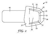
図2〜図4は、本開示によるクリップアセンブリ10の一実現例を示す。クリップアセンブリ10は、本体20と、舌部30と、ストラップ40とを含む。本体20は、基部21と、第1及び第2のアーム(22、23)と、ブリッジ24とを含み、それらが全て協働して保持区域25を画成する。第1及び第2のアーム22、23は基部21から突出し、協働して保持面を画成する。台形形状を有するものとして図示されているブリッジ24は、第1及び第2のアーム22、23を接続する。あるいは、クリップ全体が台形を模するように、接続ブリッジ24は直線状縁部を示してもよい。クリップ本体20は、正方形、多面体、円形、楕円形などを含む、任意の好適な形状を示してもよい。
2-4 illustrate one implementation of the
舌部30は、ブリッジ24の方向で基部21から突出する。舌部30は、少なくとも1つの係合表面31を含み、一般的に、保持区域25に類似した形状又は輪郭を有する。図4に示されるように、舌部30は、保持面に対して下向きの非ゼロの角度36で突出することができる。この突出角度36は、標的材料を保持区域25に挿入する際に、保持面に対して舌部を(又は舌部に対して保持面を)押し下げるのを支援することができる。他の実施形態では、舌部30は、上向きの非ゼロの角度で突出してもよく、保持面と共面であってもよく、又はブリッジ24の全体方向で保持面と平行に突出してもよい。
The
舌部30は、保持区域25の(基部からブリッジ24まで測定した)長さに等しい、又はそれよりも僅かに長い、(基部から先端33まで測定した)長さ寸法を含む。僅かに長い長さを選択することによって、標的材料を係合するように舌部30を動かしたときに、先端33とブリッジ24の一部分との間の摩擦による相互作用が可能になる(より詳細に後述する付着方法による)。使用の際、先端33は保持面の方向で押されて、ブリッジ24を係合する。先端33とブリッジ24との間の摩擦による締まりばめによって、舌部30が保持面に対してその元の位置に戻ることがなくなる。先端33とブリッジ24との間のこの相互作用はまた、ユーザに対して、クリップ10が固定されていることの聴覚的及び触覚的フィードバックを提供する。更に、標的材料の一部分は、先端33とブリッジ24との間で保持されてもよく、その境界面は材料を挟む地点として作用する。
The
概ね、舌部30は、(第1のアーム22から第2のアーム23までで測定した)保持区域よりも狭い幅を有するので、舌部は、ブリッジ24に対する係合位置と非係合位置との間をより自由に動くことができる。いくつかの実現例では、かかる幅の差は、各側において、したがって各アームに対して、少なくとも1/8インチ(0.318センチメートル)である。他の実現例では、差は各側において少なくとも1/4インチ(0.64センチメートル)である。代替実現例では、標的材料の固定は、舌部の側面と第1及び/又は第2のアームとの間の係合に少なくとも部分的に依存することがある。
Generally, the
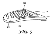
舌部30の材料係合表面31は、図2〜図4に示されるように、実質的に平滑であってもよい。図5に示されるものなど、他の実施形態では、係合表面は1つ以上の表面形状38を含んでもよい。表面形状38は、係合表面のほぼ全体、又はその任意の部分に沿って延在してもよい。好適な表面形状の例としては、様々な多面体形状、平行六面体、擬似角錐台、角錐台など、及びそれらの組み合わせを挙げることができるが、それらに限定されない。例えば、形状は、多面体、円錐、切頭円錐、角錐、切頭角錐、球、部分球、半球、楕円体、ドーム形状、レール形状、円筒、及びそれらの組み合わせであり得る。表面形状38は、特定の実現例では、標的材料がクリップ10に保持されているときの望ましくない滑動又は他の移動を防ぐ、追加の摩擦停止部を提供してもよい。
The
図3を参照して認識できるように、材料係合表面31の反対側の表面32は、支持レール34又は類似の構造を含むことができる。支持レール34は、一般的に、保持面に対して舌部30が過度に動くのを防ぎ、それによって舌部の初期位置へと向かう付勢力を保持するように設計される。更に、支持レール34は、ユーザによって過度の力が加わることにより、舌部30が不注意で破損又は弱化するのを防いで、クリップアセンブリ10が複数回の使用に利用可能であることを担保する助けとしてもよい。他の実現例では、対向表面32は、材料係合表面31に関して上述した表面形状38を含むことができる。
As can be appreciated with reference to FIG. 3, the
クリップの本体20は、金属及びプラスチックを含むがそれらに限定されない、いくつかの異なるタイプの材料で作ることができる。特に好適なプラスチックとしては、ナイロン、ポリプロピレン、及びポリカーボネートが挙げられる。舌部30は、好ましくは、本体に対して動くが、但しその元の位置に向かう付勢力を示すのに十分に、弾力性及び可撓性である。本開示にしたがって設計されたクリップ10は、潜在的に、約7重量ポンド(3kgf)の保持力を作り出すことができる。
The
クリップの本体20は、一般的には基部21において、締結ストラップ40に連結されてもよい。基部21は、例えば溶接及び接着を含む、任意の既知の定着機構によって、ストラップ40に連結されてもよい。ストラップ40は、一般的に、標的材料に固定するか又は着用者の解剖学的構造の一部分に巻き付けることができる、可撓性ベルトを備える。ストラップ40は、一般的に、弾性ラップ(又は他の標的材料)の所望の部分にしっかりと接続し、不用意な取外しを防ぐのに十分な長さのものである。
The
ストラップ40は、一般的に、発泡積層体(例えば、ポリエステル内層、ウレタン発泡体、及び外部耐久性のためのナイロンジャージーを含む積層体)、又は織布綿若しくはナイロンストラップなど、比較的非弾性の材料(例えば、約30%以下の張力下での伸展を有する材料)を含む。ストラップ40はまた、例えば、ストラップの片面又は両面に適用される、「フック・ループ式アプリケーション」のフックに類似した、締結表面を備えてもよい。締結表面は、標的材料に直接適用することができる。フック・ループ式の締結表面は、選択したフック/ループパターンに基づいて、剥離/剪断力を修正することができる機会を提供する。他の実現例では、締結表面は、接着剤(特に、感圧性接着剤)、及び標的材料と係合する他の一連の微細複製された形状(例えば、微細構造)を含む。本開示で有用な感圧性接着剤の例としては、ゴム系接着剤(例えば、粘着性を付与された天然ゴム、合成ゴム、及びスチレンブロックコポリマー)、(メタ)クリル酸(即ち、(メタ)クリレート)、ポリ(α−オレフィン)、ポリウレタン、並びにシリコーンが挙げられる。他の再配置可能又は取外し可能な接着剤も、締結表面に使用することができる。
The
あるいは、クリップアセンブリは、クリップ本体及びそれに対応する舌部が締結ストラップの両端にあるように構成することができる。他の実施形態では、クリップアセンブリは、多重ストラップ構成で接続された2つ以上のクリップ本体を含む。 Alternatively, the clip assembly can be configured such that the clip body and its corresponding tongue are at both ends of the fastening strap. In other embodiments, the clip assembly includes two or more clip bodies connected in a multiple strap configuration.
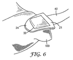
本開示はまた、上述のクリップを標的材料に、特に弾性包帯に付着させる方法を提供する。一実現例では、標的材料100の縁部又は他の区域が折り畳まれて、厚さが増加した縁部が作り出される。代替実現例では、標的材料100は、著しい変更なしでクリップ本体内に置かれる。標的材料100の縁部は、クリップ基部21の全体方向で保持区域内を動く。ユーザは、保持面に対して動かすため、舌部30又は本体20の1つに力を加えることを選択してもよい。あるいは、ユーザは、標的材料100が基部21に向かって移動するにつれて十分な力を提供することに依存してもよい。標的材料100がクリップの基部21に近付くにつれて、又はそれに先立つ任意の時点で、ユーザは、ブリッジ24の方向で舌部30を保持面に対して動かしてもよい。あるいは、ユーザは、舌部30の全体方向で本体(ブリッジを含む)を動かしてもよい。図6に示される実施形態では、舌部30はブリッジ24の上方へと動いているので、材料係合表面と反対側の表面が標的材料上にあり、それを摩擦係合している。先端33とブリッジ24との間の相互作用は、クリップが適所に固定されたことの聴覚的及び触覚的フィードバック、並びに標的材料の一部分を保定するために挟む地点を提供する。クリップが固定されると、締結ストラップ40は標的材料の別の区画に位置してもよい。あるいは、締結ストラップ40は、別のセグメントを保持区域に挿入する前に配置されてもよい。
The present disclosure also provides a method of attaching the above-described clip to a target material, particularly an elastic bandage. In one implementation, an edge or other area of the
解剖学的構造の一部分の周りで弾性包帯ラップを固定するため、ユーザは、締結ストラップ又はクリップ本体のどちらかを、弾性ラップのセグメントに付着させてもよい。ユーザは次に、所望又は支持される程度、材料を巻き付けてもよい。巻付け作業が完了すると、ユーザは、付着していないクリップ構成要素又は締結表面をラップの別のセグメントに固定してもよい。 To secure the elastic bandage wrap around a portion of the anatomy, the user may attach either a fastening strap or a clip body to the elastic wrap segment. The user may then wrap the material as desired or supported. When the winding operation is complete, the user may secure the non-attached clip component or fastening surface to another segment of the wrap.
キットの一部として、クリップは、標的材料(例えば、弾性包帯)に付着されて提供されてもよく、又は別個のユニットとして提供されてもよい。 As part of the kit, the clip may be provided attached to a target material (eg, an elastic bandage) or may be provided as a separate unit.
実施形態
1.基部、第1のアーム、第2のアーム、及びブリッジを含み、保持面を含む本体と、保持面に対する方向で基部から突出する舌部と、本体に連結されたストラップとを備え、舌部がブリッジを摩擦係合して、標的材料を本体内で固定するように動作可能である、クリップ。
2.ブリッジが、基部から離れた位置で第1及び第2のアームを接続する、請求項1に記載のクリップ。
3.保持面が、第1及び第2のアームによって少なくとも部分的に画成される、請求項1又は2に記載のクリップ。
4.舌部が保持面に対して下向きの角度で突出する、請求項1〜3のいずれかに記載のクリップ。
5.舌部が保持面に対して上向きの角度で突出する、請求項1〜3のいずれかに記載のクリップ。
6.基部、第1のアーム、第2のアーム、及びブリッジが協働して保持区域を画成する、先行する請求項のいずれかに記載のクリップ。
7.舌部が、保持区域の長さに少なくとも等しい長さ寸法を含む、請求項6に記載のクリップ。
8.舌部が、保持区域の長さよりも長い長さ寸法を含む、請求項7に記載のクリップ。
9.舌部の先端とブリッジとの間の係合により、舌部が保持面に対する初期位置に戻るのを防ぐ、先行する請求項のいずれかに記載のクリップ。
10.舌部の表面が、表面から突出する複数の表面形状を含む、先行する請求項のいずれかに記載のクリップ。
11.ストラップが1つ以上の締結表面を含む、先行する請求項のいずれかに記載のクリップ。
12.標的材料の第1のセグメントを標的材料の第2のセグメントに固定する方法であって、本体、先端を有する舌部、及び締結ストラップを含むクリップを提供し、本体が保持区域及び保持面を含み、本体が基部及び基部から離間配置されたブリッジを更に含む、工程と、締結ストラップを弾性ラップの第1のセグメントに付着させる工程と、第2のセグメントを保持区域に配置する工程と、舌部を保持面に対して動かして、ブリッジを係合する工程と、第2のセグメントの少なくとも一部を先端とブリッジとの間で固定する工程と、を含む方法。
13.標的材料の第1のセグメントを標的材料の第2のセグメントに固定する方法であって、本体、先端を有する舌部、及び締結ストラップを含むクリップを提供し、本体が保持区域及び保持面を含み、本体が基部及び基部から離間配置されたブリッジを更に含む、工程と、締結ストラップを弾性ラップの第1のセグメントに付着させる工程と、第2のセグメントの少なくとも一部を保持区域に配置する工程と、本体を保持面に対して動かして、舌部を係合する工程と、第2のセグメントの少なくとも一部を先端とブリッジとの間で固定する工程と、を含む方法。
14.ブリッジが、基部から離れた位置で第1及び第2のアームを接続する、請求項12又は13に記載の方法。
15.保持面が、第1及び第2のアームによって少なくとも部分的に画成される、先行する請求項のいずれかに記載の方法。
16.舌部が保持面に対して下向きの角度で突出する、先行する請求項のいずれかに記載の方法。
17.舌部が保持面に対して上向きの角度で突出する、請求項12〜15のいずれかに記載の方法。
18.基部、第1のアーム、第2のアーム、及びブリッジが協働して保持区域を画成する、先行する請求項のいずれかに記載の方法。
19.舌部が、保持区域の長さに少なくとも等しい長さ寸法を含む、請求項18に記載の方法。
20.舌部が、保持区域の長さよりも長い長さ寸法を含む、請求項19に記載の方法。
21.舌部の先端とブリッジとの間の係合により、舌部が保持面に対する第1の位置に戻るのを防ぐ、先行する請求項のいずれかに記載の方法。
22.舌部の表面が、表面から突出する複数の表面形状を含む、先行する請求項のいずれかに記載の方法。
23.ストラップが1つ以上の締結表面を含む、先行する請求項のいずれかに記載の方法。
24.標的材料が弾性ラップである、先行する実施形態のいずれかに記載の方法。
Embodiment 1. A body including a base, a first arm, a second arm, and a bridge, including a holding surface, a tongue protruding from the base in a direction relative to the holding surface, and a strap coupled to the body, wherein the tongue is A clip operable to frictionally engage the bridge to secure the target material within the body.
2. The clip of claim 1, wherein the bridge connects the first and second arms at a location remote from the base.
3. The clip according to claim 1 or 2, wherein the retaining surface is at least partially defined by the first and second arms.
4). The clip according to any one of claims 1 to 3, wherein the tongue projects at a downward angle with respect to the holding surface.
5. The clip according to claim 1, wherein the tongue protrudes at an upward angle with respect to the holding surface.
6). A clip according to any preceding claim, wherein the base, the first arm, the second arm, and the bridge cooperate to define a holding area.
7). 7. A clip according to claim 6, wherein the tongue comprises a length dimension at least equal to the length of the holding area.
8). The clip of claim 7, wherein the tongue includes a length dimension that is longer than a length of the retaining area.
9. A clip according to any preceding claim, wherein the engagement between the tip of the tongue and the bridge prevents the tongue from returning to its initial position relative to the holding surface.
10. A clip according to any preceding claim, wherein the surface of the tongue comprises a plurality of surface shapes protruding from the surface.
11. A clip according to any preceding claim, wherein the strap comprises one or more fastening surfaces.
12 A method of securing a first segment of target material to a second segment of target material, the clip comprising a body, a tongue having a tip, and a fastening strap, the body including a retention area and a retention surface. The body further includes a base and a bridge spaced from the base, attaching the fastening strap to the first segment of the elastic wrap, placing the second segment in the holding area, and the tongue Moving the frame relative to the retaining surface to engage the bridge and securing at least a portion of the second segment between the tip and the bridge.
13. A method of securing a first segment of target material to a second segment of target material, the clip comprising a body, a tongue having a tip, and a fastening strap, the body including a retention area and a retention surface. The body further includes a base and a bridge spaced from the base, attaching the fastening strap to the first segment of the elastic wrap, and placing at least a portion of the second segment in the holding area And moving the body relative to the retaining surface to engage the tongue and securing at least a portion of the second segment between the tip and the bridge.
14 14. A method according to claim 12 or 13, wherein the bridge connects the first and second arms at a location remote from the base.
15. A method according to any preceding claim, wherein the retaining surface is at least partially defined by the first and second arms.
16. A method according to any preceding claim, wherein the tongue protrudes at a downward angle relative to the holding surface.
17. The method according to claim 12, wherein the tongue protrudes at an upward angle with respect to the holding surface.
18. A method according to any preceding claim, wherein the base, the first arm, the second arm, and the bridge cooperate to define a holding area.
19. The method of claim 18, wherein the tongue includes a length dimension at least equal to the length of the retention zone.
20. 20. The method of claim 19, wherein the tongue includes a length dimension that is longer than the length of the retention zone.
21. A method according to any preceding claim, wherein the engagement between the tip of the tongue and the bridge prevents the tongue from returning to the first position relative to the holding surface.
22. A method according to any preceding claim, wherein the surface of the tongue comprises a plurality of surface shapes protruding from the surface.
23. A method according to any preceding claim, wherein the strap comprises one or more fastening surfaces.
24. The method according to any of the previous embodiments, wherein the target material is an elastic wrap.
本明細書に引用される特許、特許文献、及び刊行物の完全な開示内容は、あたかもそれぞれが個々に組み込まれたのと同様に、それら全体が参照により組み込まれる。本発明の範囲及び趣旨から逸脱することなく、本発明の様々な改変及び変更が当業者には明らかとなるであろう。本発明は、本明細書に記載される例示的な実施形態及び実施例によって不当に限定されるものではない点、また、こうした実施例及び実施形態はあくまで例示を目的として示されるにすぎないのであって、本発明の範囲は本明細書において以下に記載する特許請求の範囲によってのみ限定されるものである点は理解すべきである。 The complete disclosures of the patents, patent documents, and publications cited herein are incorporated by reference in their entirety as if each were individually incorporated. Various modifications and alterations of this invention will become apparent to those skilled in the art without departing from the scope and spirit of this invention. The present invention is not unduly limited by the exemplary embodiments and examples described herein, and these examples and embodiments are presented for illustrative purposes only. Thus, it should be understood that the scope of the present invention is limited only by the claims set forth herein below.
Claims (20)
前記保持面に対する方向で前記基部から突出する舌部と、
前記本体に連結されたストラップと、を備え、前記舌部が前記ブリッジを摩擦係合して、標的材料を前記本体内で固定するように動作可能である、クリップ。 A body including a base, a first arm, and a bridge and including a retaining surface;
A tongue protruding from the base in a direction relative to the holding surface;
A clip coupled to the body, wherein the tongue is operable to frictionally engage the bridge to secure a target material within the body.
本体、先端を有する舌部、及び締結ストラップを含むクリップを提供し、前記本体が保持区域及び保持面を含み、前記本体が基部及び前記基部から離間配置されたブリッジを更に含む、工程と、
前記締結ストラップを前記弾性ラップの前記第1のセグメントに付着させる工程と、
前記第2のセグメントを前記保持区域に配置する工程と、
前記舌部を前記保持面に対して動かして、前記ブリッジを係合する工程と、
前記第2のセグメントの少なくとも一部を前記先端と前記ブリッジとの間で固定する工程と、を含む方法。 A method of securing a first segment of target material to a second segment of target material comprising:
Providing a clip including a body, a tongue having a tip, and a fastening strap, wherein the body includes a retaining area and a retaining surface, and the body further includes a base and a bridge spaced from the base;
Attaching the fastening strap to the first segment of the elastic wrap;
Placing the second segment in the holding area;
Moving the tongue relative to the retaining surface to engage the bridge;
Securing at least a portion of the second segment between the tip and the bridge.
本体、先端を有する舌部、及び締結ストラップを含むクリップを提供し、前記本体が保持区域及び保持面を含み、前記本体が基部及び前記基部から離間配置されたブリッジを更に含む、工程と、
前記締結ストラップを前記弾性ラップの前記第1のセグメントに付着させる工程と、
前記第2のセグメントの前記少なくとも一部を前記保持区域に配置する工程と、
前記本体を前記保持面に対して動かして、前記舌部を係合する工程と、
前記第2のセグメントの少なくとも一部を前記先端と前記ブリッジとの間で固定する工程と、を含む方法。 A method of securing a first segment of target material to a second segment of target material comprising:
Providing a clip including a body, a tongue having a tip, and a fastening strap, wherein the body includes a retaining area and a retaining surface, and the body further includes a base and a bridge spaced from the base;
Attaching the fastening strap to the first segment of the elastic wrap;
Placing the at least part of the second segment in the holding area;
Moving the body relative to the retaining surface to engage the tongue;
Securing at least a portion of the second segment between the tip and the bridge.
Applications Claiming Priority (5)
| Application Number | Priority Date | Filing Date | Title |
|---|---|---|---|
| US201261735436P | 2012-12-10 | 2012-12-10 | |
| US61/735,436 | 2012-12-10 | ||
| US201361783672P | 2013-03-14 | 2013-03-14 | |
| US61/783,672 | 2013-03-14 | ||
| PCT/US2013/073000 WO2014093077A1 (en) | 2012-12-10 | 2013-12-04 | Universal locking clip |
Publications (2)
| Publication Number | Publication Date |
|---|---|
| JP2016502044A true JP2016502044A (en) | 2016-01-21 |
| JP2016502044A5 JP2016502044A5 (en) | 2017-01-19 |
Family
ID=50934833
Family Applications (1)
| Application Number | Title | Priority Date | Filing Date |
|---|---|---|---|
| JP2015545803A Pending JP2016502044A (en) | 2012-12-10 | 2013-12-04 | Universal locking clip |
Country Status (8)
| Country | Link |
|---|---|
| US (1) | US20150342803A1 (en) |
| EP (1) | EP2928434B1 (en) |
| JP (1) | JP2016502044A (en) |
| CN (1) | CN104837460B (en) |
| AU (1) | AU2013360073B2 (en) |
| BR (1) | BR112015014047A2 (en) |
| TW (1) | TW201429462A (en) |
| WO (1) | WO2014093077A1 (en) |
Families Citing this family (5)
| Publication number | Priority date | Publication date | Assignee | Title |
|---|---|---|---|---|
| SE538588C2 (en) | 2015-03-25 | 2016-09-27 | Presscise Ab | A bandage securing device |
| US20170042298A1 (en) * | 2015-08-12 | 2017-02-16 | Ted Greg Lee Frumkin | Gecko Jewelry |
| US10486582B1 (en) * | 2015-11-20 | 2019-11-26 | Micah Hamm | Ratchet strap keeper |
| FR3086917B1 (en) * | 2018-10-05 | 2021-05-28 | Plastic Omnium Cie | RETAINING DEVICE FOR A BLOCKING HATCH OF AN OPENING SHAPED IN A WALL OF A BODY PART |
| US20240058183A1 (en) * | 2022-08-17 | 2024-02-22 | Hames Industries Llc | Light weight clip to provide adjustable tie down point for bandage to enable pressure to be applied to inguinal wounds |
Citations (4)
| Publication number | Priority date | Publication date | Assignee | Title |
|---|---|---|---|---|
| JPS54116423U (en) * | 1978-02-01 | 1979-08-15 | ||
| JP3032689U (en) * | 1996-06-21 | 1996-12-24 | 英行 平出 | clip |
| JP3053933U (en) * | 1998-03-11 | 1998-11-17 | 朱美 岩井田 | Bookmarker pen |
| JP3170360U (en) * | 2011-06-22 | 2011-09-15 | 山本 修一 | Expansion and contraction |
Family Cites Families (9)
| Publication number | Priority date | Publication date | Assignee | Title |
|---|---|---|---|---|
| US2820456A (en) * | 1955-03-21 | 1958-01-21 | Sidney A Peerless | Surgical bandage |
| CH359241A (en) * | 1958-07-17 | 1961-12-31 | Roedl Baumann Karola Geb | Retaining clips, in particular for surgical and orthopedic bandages |
| US3036572A (en) * | 1960-07-11 | 1962-05-29 | Johnson & Johnson | Bandage and securing means |
| DE1195903B (en) * | 1963-12-07 | 1965-07-01 | Karl Otto Braun K G | Bandage clip |
| US3373742A (en) * | 1965-09-02 | 1968-03-19 | United Carr Inc | Bandage fastener and assembly |
| US3863301A (en) * | 1972-12-29 | 1975-02-04 | Harry H Leveen | Elastic bandage and fastener therefor |
| US3857140A (en) * | 1973-02-28 | 1974-12-31 | Rubricius J | Detachable bandage clasp |
| GB1505288A (en) * | 1975-01-10 | 1978-03-30 | Takano Atsushi | Fastener made of synthetic resin |
| US4586499A (en) * | 1984-03-19 | 1986-05-06 | Esther Kaletzky | Surgical bandage disposable coupling device |
-
2013
- 2013-12-04 CN CN201380064371.XA patent/CN104837460B/en not_active Expired - Fee Related
- 2013-12-04 AU AU2013360073A patent/AU2013360073B2/en not_active Ceased
- 2013-12-04 EP EP13863657.6A patent/EP2928434B1/en not_active Not-in-force
- 2013-12-04 US US14/649,854 patent/US20150342803A1/en not_active Abandoned
- 2013-12-04 JP JP2015545803A patent/JP2016502044A/en active Pending
- 2013-12-04 BR BR112015014047A patent/BR112015014047A2/en not_active IP Right Cessation
- 2013-12-04 WO PCT/US2013/073000 patent/WO2014093077A1/en active Application Filing
- 2013-12-09 TW TW102145187A patent/TW201429462A/en unknown
Patent Citations (4)
| Publication number | Priority date | Publication date | Assignee | Title |
|---|---|---|---|---|
| JPS54116423U (en) * | 1978-02-01 | 1979-08-15 | ||
| JP3032689U (en) * | 1996-06-21 | 1996-12-24 | 英行 平出 | clip |
| JP3053933U (en) * | 1998-03-11 | 1998-11-17 | 朱美 岩井田 | Bookmarker pen |
| JP3170360U (en) * | 2011-06-22 | 2011-09-15 | 山本 修一 | Expansion and contraction |
Also Published As
| Publication number | Publication date |
|---|---|
| AU2013360073B2 (en) | 2016-12-15 |
| AU2013360073A1 (en) | 2015-06-18 |
| WO2014093077A1 (en) | 2014-06-19 |
| US20150342803A1 (en) | 2015-12-03 |
| TW201429462A (en) | 2014-08-01 |
| EP2928434B1 (en) | 2017-08-09 |
| CN104837460A (en) | 2015-08-12 |
| EP2928434A1 (en) | 2015-10-14 |
| CN104837460B (en) | 2017-09-22 |
| BR112015014047A2 (en) | 2017-07-11 |
| EP2928434A4 (en) | 2016-08-10 |
Similar Documents
| Publication | Publication Date | Title |
|---|---|---|
| JP2016502044A (en) | Universal locking clip | |
| US20190297979A1 (en) | Non-adhesive false eyelash system and method | |
| JP3134280U (en) | Wig fitting | |
| US5015251A (en) | Medical fastener strap | |
| JP4882000B2 (en) | Wig fixing member and wig fixing method using the wig fixing member | |
| KR100323819B1 (en) | Fastening device and method of use | |
| US20110172582A1 (en) | Wound dressing retainer | |
| US4569348A (en) | Catheter tube holder strap | |
| US6328038B1 (en) | Nasal cannula retainer | |
| US10543968B2 (en) | Low profile, wrappable elongate members spacer and method of maintaining elongate members in fixed, spaced relative relation | |
| JP2016526414A5 (en) | ||
| US20220001124A1 (en) | Tube securement system | |
| RU2452356C2 (en) | Device for putting on wig | |
| KR102608393B1 (en) | A pneumatic tourniquet | |
| US20040006854A1 (en) | Self-attaching elastic cord | |
| US20190366050A1 (en) | Catheter securement systems, kits and methods of using same | |
| JP2020505139A5 (en) | ||
| WO2015013093A1 (en) | Adjustable wound dressing | |
| JP2009291380A (en) | Medical instrument having incorrect needle removal preventive function and hemostatic function | |
| CN102438480A (en) | Hook and loop tie with a non-slip area | |
| WO2014196867A1 (en) | Support and compression device for a hand and a forearm | |
| CN218106211U (en) | Emergency wound bandage | |
| JPH11509439A (en) | Elastic wrap with repositionable fasteners that can be locked in any position | |
| JP2001145655A (en) | Strap | |
| AU2019100633A4 (en) | Magnetic holding strap |
Legal Events
| Date | Code | Title | Description |
|---|---|---|---|
| A521 | Request for written amendment filed |
Free format text: JAPANESE INTERMEDIATE CODE: A523 Effective date: 20161130 |
|
| A621 | Written request for application examination |
Free format text: JAPANESE INTERMEDIATE CODE: A621 Effective date: 20161130 |
|
| A977 | Report on retrieval |
Free format text: JAPANESE INTERMEDIATE CODE: A971007 Effective date: 20170927 |
|
| A131 | Notification of reasons for refusal |
Free format text: JAPANESE INTERMEDIATE CODE: A131 Effective date: 20171107 |
|
| RD03 | Notification of appointment of power of attorney |
Free format text: JAPANESE INTERMEDIATE CODE: A7423 Effective date: 20171120 |
|
| RD04 | Notification of resignation of power of attorney |
Free format text: JAPANESE INTERMEDIATE CODE: A7424 Effective date: 20171122 |
|
| A02 | Decision of refusal |
Free format text: JAPANESE INTERMEDIATE CODE: A02 Effective date: 20180508 |