JP2016501437A - Cable to board connector - Google Patents
Cable to board connector Download PDFInfo
- Publication number
- JP2016501437A JP2016501437A JP2015549441A JP2015549441A JP2016501437A JP 2016501437 A JP2016501437 A JP 2016501437A JP 2015549441 A JP2015549441 A JP 2015549441A JP 2015549441 A JP2015549441 A JP 2015549441A JP 2016501437 A JP2016501437 A JP 2016501437A
- Authority
- JP
- Japan
- Prior art keywords
- cable
- groove
- different
- contact
- wire
- Prior art date
- Legal status (The legal status is an assumption and is not a legal conclusion. Google has not performed a legal analysis and makes no representation as to the accuracy of the status listed.)
- Withdrawn
Links
Images


Classifications
-
- H—ELECTRICITY
- H01—ELECTRIC ELEMENTS
- H01R—ELECTRICALLY-CONDUCTIVE CONNECTIONS; STRUCTURAL ASSOCIATIONS OF A PLURALITY OF MUTUALLY-INSULATED ELECTRICAL CONNECTING ELEMENTS; COUPLING DEVICES; CURRENT COLLECTORS
- H01R12/00—Structural associations of a plurality of mutually-insulated electrical connecting elements, specially adapted for printed circuits, e.g. printed circuit boards [PCB], flat or ribbon cables, or like generally planar structures, e.g. terminal strips, terminal blocks; Coupling devices specially adapted for printed circuits, flat or ribbon cables, or like generally planar structures; Terminals specially adapted for contact with, or insertion into, printed circuits, flat or ribbon cables, or like generally planar structures
- H01R12/70—Coupling devices
- H01R12/71—Coupling devices for rigid printing circuits or like structures
- H01R12/75—Coupling devices for rigid printing circuits or like structures connecting to cables except for flat or ribbon cables
-
- H—ELECTRICITY
- H01—ELECTRIC ELEMENTS
- H01R—ELECTRICALLY-CONDUCTIVE CONNECTIONS; STRUCTURAL ASSOCIATIONS OF A PLURALITY OF MUTUALLY-INSULATED ELECTRICAL CONNECTING ELEMENTS; COUPLING DEVICES; CURRENT COLLECTORS
- H01R12/00—Structural associations of a plurality of mutually-insulated electrical connecting elements, specially adapted for printed circuits, e.g. printed circuit boards [PCB], flat or ribbon cables, or like generally planar structures, e.g. terminal strips, terminal blocks; Coupling devices specially adapted for printed circuits, flat or ribbon cables, or like generally planar structures; Terminals specially adapted for contact with, or insertion into, printed circuits, flat or ribbon cables, or like generally planar structures
- H01R12/70—Coupling devices
- H01R12/71—Coupling devices for rigid printing circuits or like structures
- H01R12/712—Coupling devices for rigid printing circuits or like structures co-operating with the surface of the printed circuit or with a coupling device exclusively provided on the surface of the printed circuit
- H01R12/716—Coupling device provided on the PCB
-
- H—ELECTRICITY
- H01—ELECTRIC ELEMENTS
- H01R—ELECTRICALLY-CONDUCTIVE CONNECTIONS; STRUCTURAL ASSOCIATIONS OF A PLURALITY OF MUTUALLY-INSULATED ELECTRICAL CONNECTING ELEMENTS; COUPLING DEVICES; CURRENT COLLECTORS
- H01R12/00—Structural associations of a plurality of mutually-insulated electrical connecting elements, specially adapted for printed circuits, e.g. printed circuit boards [PCB], flat or ribbon cables, or like generally planar structures, e.g. terminal strips, terminal blocks; Coupling devices specially adapted for printed circuits, flat or ribbon cables, or like generally planar structures; Terminals specially adapted for contact with, or insertion into, printed circuits, flat or ribbon cables, or like generally planar structures
- H01R12/70—Coupling devices
- H01R12/77—Coupling devices for flexible printed circuits, flat or ribbon cables or like structures
- H01R12/79—Coupling devices for flexible printed circuits, flat or ribbon cables or like structures connecting to rigid printed circuits or like structures
-
- H—ELECTRICITY
- H01—ELECTRIC ELEMENTS
- H01R—ELECTRICALLY-CONDUCTIVE CONNECTIONS; STRUCTURAL ASSOCIATIONS OF A PLURALITY OF MUTUALLY-INSULATED ELECTRICAL CONNECTING ELEMENTS; COUPLING DEVICES; CURRENT COLLECTORS
- H01R13/00—Details of coupling devices of the kinds covered by groups H01R12/70 or H01R24/00 - H01R33/00
- H01R13/648—Protective earth or shield arrangements on coupling devices, e.g. anti-static shielding
- H01R13/658—High frequency shielding arrangements, e.g. against EMI [Electro-Magnetic Interference] or EMP [Electro-Magnetic Pulse]
- H01R13/6581—Shield structure
-
- H—ELECTRICITY
- H01—ELECTRIC ELEMENTS
- H01R—ELECTRICALLY-CONDUCTIVE CONNECTIONS; STRUCTURAL ASSOCIATIONS OF A PLURALITY OF MUTUALLY-INSULATED ELECTRICAL CONNECTING ELEMENTS; COUPLING DEVICES; CURRENT COLLECTORS
- H01R31/00—Coupling parts supported only by co-operation with counterpart
- H01R31/06—Intermediate parts for linking two coupling parts, e.g. adapter
Abstract
本発明は、ファインピッチの高速コネクタアセンブリ用のケーブル対基板コネクタに関する。代表的なコネクタアセンブリは、絶縁ハウジングと、ハウジング内に配設された複数の第1接触子を含み、少なくとも接触子の一部分は、プリント回路基板上の導電性配線と、複数の第1ワイヤを含む第1ケーブルとを終端するように適合されている。各第1接触子は、嵌合コネクタの対応する接触子と電気的接触を形成するための第1嵌合部分と、ハウジングの底部に沿って延びる第1末端部分とを有し、第1末端部分は、プリント回路基板上の導電性配線で終端するように適合されている。代表的なケーブルアセンブリでは、第1ケーブルの各第1ワイヤは、異なる第1接触子の第1末端部分において終端される。【選択図】図3The present invention relates to a cable-to-board connector for a fine pitch high speed connector assembly. A typical connector assembly includes an insulating housing and a plurality of first contacts disposed within the housing, at least a portion of the contacts including conductive wiring on the printed circuit board and a plurality of first wires. Adapted to terminate the first cable including. Each first contact has a first mating portion for making electrical contact with a corresponding contact of the mating connector, and a first end portion extending along the bottom of the housing. The portion is adapted to terminate with conductive traces on the printed circuit board. In a typical cable assembly, each first wire of the first cable is terminated at a first end portion of a different first contact. [Selection] Figure 3
Description
本出願の発明は、ケーブル対基板コネクタに関し、より具体的にはバックプレーン用途のための、ファインピッチの高速ケーブル対基板接続システムに関する。 The invention of this application relates to cable-to-board connectors, and more particularly to a fine pitch, high-speed cable-to-board connection system for backplane applications.
この10年間にわたって、携帯通信デバイス及びラップトップなどの消費者向け電子機器における、よりコンパクトでより高速な設計への傾向は、ケーブルをプリント回路基板(PCB)に取り付けるための様々な薄型電子機器コネクタの開発につながった。高速伝送の要件を満たすために、コネクタは、ギガヘルツ(GHz)周波数範囲を超える高いパファーマンスを呈するように設計される必要がある。1つの重要な設計要件は、コネクタ内の信号劣化現象を、信号品質に悪影響を与えない程度に十分低いレベルまで低減させることである。同時に、他の設計要件は、コネクタ構成要素の機械的強度、コネクタが特定の空間に収まることができるような十分に小さいコネクタ寸法及び高さ外形、等々を含むように維持されるべきである。 Over the last decade, the trend towards more compact and faster designs in consumer electronic devices such as portable communication devices and laptops has led to a variety of thin electronic connectors for attaching cables to printed circuit boards (PCBs). Led to the development of. In order to meet the requirements for high-speed transmission, the connector needs to be designed to exhibit high performance beyond the gigahertz (GHz) frequency range. One important design requirement is to reduce the signal degradation phenomenon in the connector to a sufficiently low level that it does not adversely affect signal quality. At the same time, other design requirements should be maintained to include the mechanical strength of the connector components, sufficiently small connector dimensions and height profiles such that the connector can fit in a particular space, and so on.
よりコンパクトでより高速な電子機器への市場傾向は、現在、サーバ市場へと更に拡大しており、従来の大型サーバと同じ速度で機能し得るマイクロサーバを求める要求が存在する。従来のサーバは、サーバユニットを繋げるための2mmの接続ピッチを有するバックプレーンコネクタを使用し得る。現行のバックプレーンコネクタの2mmのピッチは、マイクロサーバに求められるバックプレーンPCBよりも大きいバックプレーンPCBを必要とする。したがって、例えばマイクロサーバ市場用のバックプレーンPCBの寸法を低減するのに役立つような、高速用途のための更に小型でファインピッチのケーブル対基板コネクタが求められている。コネクタはまた、広範囲の周波数にわたって高いデータ伝送速度で動作する際の改善された信号の完全性及び性能、加えて、機械的応力に抗するための改善された機械的特性、及び設計特徴も有するべきである。 The market trend towards more compact and faster electronic devices is now further expanding into the server market, and there is a need for a microserver that can function at the same speed as conventional large servers. A conventional server may use a backplane connector having a connection pitch of 2 mm for connecting server units. The 2 mm pitch of current backplane connectors requires a larger backplane PCB than the backplane PCB required for microservers. Accordingly, there is a need for a smaller, fine pitch cable-to-board connector for high speed applications that helps reduce the size of backplane PCBs for the microserver market, for example. The connector also has improved signal integrity and performance when operating at high data rates over a wide range of frequencies, as well as improved mechanical properties and design features to resist mechanical stress. Should.
本発明は、ケーブル対基板コネクタに関し、より具体的には、バックプレーン用途の、ファインピッチの高速ケーブル対基板コネクタアセンブリに関する。第1の代表的な実施形態では、コネクタアセンブリは、絶縁ハウジング、ハウジング内に配設された複数の第1接触子、及び複数の第1ワイヤを含む第1ケーブルを含む。各第1接触子は、嵌合コネクタの対応する接触子と電気的接触を形成するための第1嵌合部分と、ハウジングの底部に沿って延びる第1末端部分とを有し、第1末端部分は、プリント回路基板上の導電性配線で終端するように適合されている。代表的なケーブルアセンブリでは、第1ケーブルの各第1ワイヤは、異なる第1接触子の第1末端部分において終端される。 The present invention relates to cable-to-board connectors and, more particularly, to fine pitch, high-speed cable-to-board connectors assemblies for backplane applications. In a first exemplary embodiment, a connector assembly includes an insulating housing, a plurality of first contacts disposed within the housing, and a first cable including a plurality of first wires. Each first contact has a first mating portion for making electrical contact with a corresponding contact of the mating connector, and a first end portion extending along the bottom of the housing. The portion is adapted to terminate with conductive traces on the printed circuit board. In a typical cable assembly, each first wire of the first cable is terminated at a first end portion of a different first contact.
別の代表的な実施形態では、コネクタアセンブリは、絶縁ハウジングと、ハウジング内に配設された複数の第1接触子及び複数の第2接触子であって、第1及び/又は第2接触子の少なくとも一部分は、プリント回路基板上の導電性配線で終端されるように適合される、複数の第1接触子及び複数の第2接触子と、第1接触子において終端された複数の第1ワイヤと、第2接触子において終端された複数の第2ワイヤとを含む。各第1接触子は、嵌合コネクタの対応する接触子と電気的接触を形成するための第1嵌合部分と、ハウジング底部に沿って延びる第1末端部分とを有し、各第2接触子は、嵌合コネクタの対応する接触子と電気的接触を形成するための第2嵌合部分と、ハウジング底部に沿って延びる第2末端部分とを有し、第1及び第2末端部分は、プリント回路基板上の導電性配線において終端するように適合されている。各第1ワイヤは、異なる第1接触子の第1末端部分において終端しており、各第2ワイヤは、異なる第2接触子の第2末端部分において終端している。 In another exemplary embodiment, the connector assembly includes an insulating housing, a plurality of first contacts and a plurality of second contacts disposed in the housing, wherein the first and / or second contacts At least a portion of the plurality of first contacts and the plurality of second contacts adapted to be terminated with conductive wiring on the printed circuit board, and the plurality of first contacts terminated at the first contact. A wire and a plurality of second wires terminated at the second contact. Each first contact has a first mating portion for making electrical contact with a corresponding contact of the mating connector, and a first end portion extending along the bottom of the housing, each second contact The child has a second mating portion for making electrical contact with a corresponding contact of the mating connector, and a second end portion extending along the bottom of the housing, the first and second end portions being Adapted to terminate in conductive wiring on the printed circuit board. Each first wire terminates at a first end portion of a different first contact, and each second wire terminates at a second end portion of a different second contact.
別の代表的な実施形態では、本発明は、ケーブルコネクタに関する。代表的なケーブルコネクタは、絶縁ハウジング、複数の第1接触子、及び絶縁ハウジングに取り付けられたケーブルオーガナイザを含む。各第1接触子は、嵌合コネクタの対応する接触子と電気的接触を形成するための第1嵌合部分と、ハウジングの底部に沿って延びる第1末端部分とを有し、第1末端部分は、プリント回路基板上の導電性配線で終端するように適合されている。ケーブルオーガナイザは、ハウジング底部に隣接するように配設され、かつ同じ第1方向に沿って延びる複数の第1の溝と複数の第1開口部とを含み、複数の第1接触子の前記末端部分にアクセスし、各第1の溝内部に配設されたワイヤをこの末端部と接続するように、各第1開口部は異なる第1の溝に対応し、かつ前記異なる第1の溝と並んでいる。 In another exemplary embodiment, the present invention relates to a cable connector. A typical cable connector includes an insulating housing, a plurality of first contacts, and a cable organizer attached to the insulating housing. Each first contact has a first mating portion for making electrical contact with a corresponding contact of the mating connector, and a first end portion extending along the bottom of the housing. The portion is adapted to terminate with conductive traces on the printed circuit board. The cable organizer includes a plurality of first grooves and a plurality of first openings that are disposed adjacent to the bottom of the housing and extend along the same first direction, and the terminal ends of the plurality of first contacts Each first opening corresponds to a different first groove and is connected to the different first groove so as to access the portion and connect the wire disposed within each first groove to this end. Are lined up.
別の代表的な実施形態では、本発明は、ケーブル対基板コネクタシステム内で使用するためのケーブルオーガナイザに関する。ケーブルアセンブリは、中央トラフを有するオーガナイザ基部を有し、中央トラフは、第1深さで配設された第1フロア区分、第2深さで配設された第2フロア区分、及び第1フロア区分から第2フロア区分まで延びる側壁部を有する。複数の第1の溝は、第1フロア区分に沿って延び、かつ中央トラフの側壁部に対して平行であり、第1の溝は複数の第1ワイヤを位置付けるのに役立つ。ケーブルオーガナイザは、複数の第1ワイヤを更に含む。各第1開口部は、異なる第1の溝と対応し、かつ異なる第1の溝と整列して、各第1ワイヤが終端し、第1末端部分により、コネクタアセンブリ内にて終端するようにする。 In another exemplary embodiment, the present invention relates to a cable organizer for use in a cable-to-board connector system. The cable assembly has an organizer base having a central trough, the central trough having a first floor section disposed at a first depth, a second floor section disposed at a second depth, and a first floor. Having a side wall extending from the section to the second floor section; The plurality of first grooves extends along the first floor section and is parallel to the side wall of the central trough, the first grooves help to position the plurality of first wires. The cable organizer further includes a plurality of first wires. Each first opening corresponds to a different first groove and is aligned with a different first groove such that each first wire terminates and terminates in the connector assembly by a first end portion. To do.
本発明は更に、本明細書に記載されるか又は添付図面に示される部品又は特性のあらゆる代替的な組み合わせを含む。明示的には記載されていないこれらの部品又は特性の既知の同等物も、やはり含まれるものと見なされる。 The invention further includes any alternative combination of parts or features described herein or shown in the accompanying drawings. Known equivalents of these parts or properties not explicitly described are also considered to be included.
本発明の例示の形態は、これより以下の添付の図面を参照して記載される。 Exemplary forms of the invention will now be described with reference to the accompanying drawings in which:
上で特定した図面は、本発明のいくつかの実施形態を示しているが、考察部分で述べているように、他の実施形態も考えられる。いずれのケースでも、本開示は、限定する目的ではなく、説明する目的で本発明を提示する。本発明の原理の範囲及び趣旨に含まれる多数の他の修正及び実施形態が、当業者によって考案され得ることを理解されたい。図は、縮尺どおりに描かれていない場合もある。図の全体にわたって、同様の参照番号を用いて同様の部分を示している。 Although the above-identified drawings show some embodiments of the present invention, other embodiments are also contemplated, as discussed in the discussion section. In any case, this disclosure presents the invention by way of illustration and not limitation. It should be understood that numerous other modifications and embodiments within the scope and spirit of the principles of the invention may be devised by those skilled in the art. The figures may not be drawn to scale. Throughout the figures, like reference numerals are used to indicate like parts.
以下の好適な実施形態の詳細な説明では、その一部をなす添付の図面を参照する。添付の図面は、本発明を実施することが可能な具体的な実施形態を例として示す。他の実施形態を利用することも可能であり、また、本発明の範囲から逸脱することなく、構造的又は論理的な変更を行い得ることは理解されるべきである。したがって、以下の詳細な説明は限定的な意味で解釈されるべきものではなく、本発明の範囲は、添付の特許請求の範囲によって定義されるものである。 In the following detailed description of the preferred embodiments, reference is made to the accompanying drawings that form a part hereof. The accompanying drawings show, by way of illustration, specific embodiments in which the invention can be practiced. It is to be understood that other embodiments may be utilized and structural or logical changes may be made without departing from the scope of the present invention. The following detailed description is, therefore, not to be taken in a limiting sense, and the scope of the present invention is defined by the appended claims.
新しいファインピッチの高速ケーブルアセンブリ(例えば、マイクロサーバ用途)のニーズを満たすために、新しいファインピッチの高速ケーブル対基板コネクタシステムが設計されてきた。代表的なケーブル対基板コネクタシステムは、従来のファインピッチの、基板に取り付けられたコネクタに嵌合し得る、新しい、ケーブルに取り付けられたコネクタを含む。代表的態様では、代表的なファインピッチの高速ケーブルにおけるワイヤピッチは、ケーブル内のワイヤ直径に一部依存して、約0.3mm〜約1.0mm、又は好ましくは約0.5mm〜約0.9mmであり得る。言うまでもなく、本発明に記載の新しいファインピッチケーブルコネクタを使用した代表的なケーブルコネクタ及び代表的なケーブルアセンブリは、より大きなワイヤピッチも収容し得る。 To meet the needs of new fine pitch high speed cable assemblies (eg, microserver applications), new fine pitch high speed cable-to-board connector systems have been designed. A typical cable-to-board connector system includes a new, cable-mounted connector that can mate with a conventional fine-pitch, board-mounted connector. In an exemplary embodiment, the wire pitch in a typical fine pitch high speed cable is about 0.3 mm to about 1.0 mm, or preferably about 0.5 mm to about 0, depending in part on the wire diameter in the cable. .9 mm. Of course, typical cable connectors and exemplary cable assemblies using the new fine pitch cable connectors described in the present invention can accommodate larger wire pitches.
代表的な態様では、本発明の新しい高速ケーブルコネクタ及び得られたケーブル対基板アセンブリは、その全体が参照により本明細書に組み込まれる、PCT公開第WO2011/119277号、及びPCT出願第US2012/046481号などの現行の高速基板対基板コネクタ設計と互換性があり得る。代表的なケーブル対基板アセンブリを、従来の高速の基板対基板コネクタに基づいて設計することにより、新しいケーブルコネクタと従来の基板に取り付けられたコネクタとの接続互換性が保証される。本発明に記載の、より小型で新しいケーブル対基板コネクタシステムに加えて、新しいケーブル対基板のケーブルシステムは、アセンブリのハウジングが、従来の基板に取り付けられたコネクタを多目的に使用でき、これにより、在庫になり得る部品数を低減するという利点を有する。 In exemplary aspects, the new high-speed cable connector and resulting cable-to-board assembly of the present invention is described in PCT Publication No. WO2011 / 119277, and PCT Application No. US2012 / 046481, which is incorporated herein by reference in its entirety. Compatible with current high speed board to board connector designs such as Designing a typical cable-to-board assembly based on a conventional high-speed board-to-board connector ensures connection compatibility between the new cable connector and the connector attached to the conventional board. In addition to the smaller and newer cable-to-board connector system described in the present invention, the new cable-to-board cable system allows the assembly housing to be multipurposely used with a connector attached to a conventional board, thereby It has the advantage of reducing the number of parts that can be in stock.
図1は、本発明による、高速ケーブル対基板のケーブルアセンブリ50の例を図示する。ケーブルアセンブリ50は、高速ケーブル20の終端部に取り付けられた第1ケーブルコネクタ102及び第2ケーブルコネクタ102’を有する。第1及び第2ケーブルコネクタは、第1基板取り付けコネクタ200、及び第2基板取り付けコネクタ200’とそれぞれ嵌合する。ケーブルコネクタ102及び102’と、基板に取り付けられたコネクタ200、200’との組み合わせは、代表的なケーブル対基板コネクタシステム100、100’をそれぞれ形成する。代表的なケーブルアセンブリは、バックプレーン接続システムを必要とすることなく、2つのプリント回路基板(PCB)5、5’を相互接続するために使用されることができるので、複数のPCBを有する電子機器の設計の柔軟性を高める。あるいは、ケーブルアセンブリ50は、2つの別個の電子機器部品を相互接続するために使用され得る。代表的なケーブルアセンブリは、2つのPCBの間、2つの電子機器部品の間に高速接続(すなわち、データ伝送速度が最大で約20Gb/sを有する)を提供し得、又は電子機器部品をPCBに接続するために高速接続を提供し得る。
FIG. 1 illustrates an example of a high speed cable to board
第1ケーブルコネクタ102、及び第2ケーブルコネクタ102’を相互接続する高速ケーブルは、複数の導電体すなわちワイヤを含み得る。代表的な態様では、高速ケーブルは、米国特許公開第2012/0090873号、同第2012/0090872号、同第2012/0090866号、及び同第2012/0097421号などのファインピッチの高速リボンケーブルであり得、これら全てはその全体が本明細書に参考として組み込まれる。これら参考文献のケーブルは、他の従来の電気リボンケーブルよりも高い導体密度を実現する。1つの代表的な態様は、ケーブル内の導体間のピッチは、コネクタアセンブリ内の接触子の間隔に近似する。他の代表的なケーブルは、例えば、Ribbon X(38 & 40 AWG Ribbon Coax)及びBulk 0.050”Pitch Flat Ribbon Cableを含む(両方ともHitachi Cable,Incから入手可能)。
The high speed cable interconnecting the
図2は、本発明の実施形態による、接続していない状態のケーブル対基板コネクタ100を図示する。図2に示された代表的な態様では、ケーブル対基板コネクタシステム100は、PCB 5に取り付けられた状態の、プラグ型の基板に取り付けられたコネクタ200と嵌合するソケット型のケーブルコネクタ102を含む。別の態様では、ケーブル対基板コネクタシステムは、ソケット型の基板に取り付けられたコネクタ(PCBに取り付けられた状態の)と嵌合する、プラグ型のケーブルコネクタを含んでもよく、これらは、以降で図8及び9と関して説明される。代表的なケーブル対基板コネクタアセンブリは、プラグ構成又はソケット構成のいずれかを有し得るが、代表的なソケット型のケーブルコネクタ102は、図2〜5Dに関して以下に詳細に記載される。
FIG. 2 illustrates the cable-to-
図2、3、及び4A〜4Bを参照して、ケーブルコネクタ102は、接続基部120、ケーブルオーガナイザ150及びキャップ110を含み得る。
With reference to FIGS. 2, 3, and 4 </ b> A- 4 </ b> B, the
接続基部120は、複数の第1接触子130を保持するように構成された絶縁ハウジング122を含み得る。絶縁ハウジング122は、ハウジング基部127から延びる1対の側壁部126によって画定された凹部125を含む。凹部125を囲む側壁部は、1対の端部壁124によって、その端部において互いに連結され得る。
The
代表的な態様では、接続基部120の絶縁ハウジング122、ケーブルオーガナイザ150及びキャップ110は、例えば、ガラス充填された液晶ポリマ樹脂、ポリブチレンテレフタレート(PBT)樹脂、ポリカーボネート樹脂などのエンジニアリング樹脂を射出成形するプロセスを使用して、形成され得る。
In a typical embodiment, the insulating
ハウジング基部127は、ハウジング基部の外側表面内に形成された複数の接触子チャネル127aを有し得る。各接触子チャネル127aは、各接触子チャネル127aの底部を通る接触子開口部127bを有し得、これにより、第1接触子130の一部が、ハウジング基部を通って、凹部125内に、及び側壁部126の少なくとも1つの内側表面内に形成された対応する接触子チャネル126a内へと通ることが可能となる。
The
代表的な態様では、接続基部120は、絶縁ハウジング122の外側表面上に配設された複数の保持装置(図示せず)を含み得ることにより、任意の補助的な遮断プレート160の取り付けを可能にする。補助的な遮断プレート160は、ケーブルコネクタ102に対する外部環境からのEMIの、更なる手段を提供し得る。したがって、外部環境から良好にEMIを遮断することを提供することが不可欠ではない用途において、コネクタアセンブリは、補助的な遮断プレートを必要とし得ない。
In an exemplary embodiment, the
1つの代表的な態様では、各第1接触子130は、概ね「L」字形状であり得る。各第1接触子130は、側壁部126、126’の一方の中に形成された接触子チャネル126a内に配設され、かつ嵌合コネクタの対応する接触子と電気的接触を形成するためのハウジング凹部125内を延びる第1嵌合部分132と、接触子チャネル127a内でハウジング基部に沿って延びる第1末端部分134とを有する。第1末端部分は、接続基部が基板対基板接続において使用される場合、プリント回路基板上の導電性配線で終端するように適合され得、又は本発明に記載のように、基板に取り付けられたコネクタ(例えば、図2に図示された基板に取り付けられたコネクタ200)に対するケーブル内のワイヤを終端するように適合され得る。したがって、本発明の代表的なケーブル対基板コネクタでは、各第1末端部分は、高速ケーブル20のワイヤ25を終端させるために使用され得る。
In one exemplary aspect, each
代表的な態様では、ケーブルコネクタ102は、複数の第2接触子140を更に含む。第2接触子140はまた、概ね「L」形状であり得る。各第2接触子140は、絶縁ハウジング122の側壁部126’に形成された接触子チャネル126a’内に配設された第2嵌合部分142を有する。第2接触子は、嵌合コネクタの対応する接触子と電気的接触を形成するために、ハウジング凹部125内に延びる。各第2接触子は、接触子チャネル127a内をハウジング基部に沿って延びる第2末端部分144を含む。第2末端部分は、接続基部が基板対基板コネクタにおいて使用される場合、プリント回路基板上の導電性配線において終端するように適合され得、又は本発明のケーブル対基板接続システム内でワイヤを終端するように適合され得る。したがって、各第2末端部分は、図4Aに図示されるように、第2高速ケーブル20’のワイヤ25’を終端させるために使用され得る。
In an exemplary embodiment, the
ケーブルオーガナイザ150は、接続基部120に取り付けられ得、これにより、1つ以上の高速ケーブル20、20’のワイヤ25、25’と、接続基部内に配設された接触子130、140とを整列させるのに役立つ。具体的には、接続基部120は、ケーブルオーガナイザを通って配設された整列穴158と嵌合する1つ以上の整列ポスト128を含み得る。図に示された代表的態様では、整列ポスト128及び対応する整列穴158はD字形状を有し、これは接続基部上にケーブルオーガナイザを位置付けるのに役立つ。しかしながら、例えば、正方形のポスト及び穴、円形のポスト及び穴などの別の形状が可能であり、整列ポストの形状及び対応する整列穴は、本発明に記載の代表的なケーブル対基板コネクタシステムに対して限定するものと見なされない。
The
加えて、ケーブルオーガナイザ150は、その下部表面から延びる複数のラッチアーム159を有し得るオーガナイザ基部152を含み、これにより、ケーブルオーガナイザを接続基部120に取り付ける。ラッチアーム159は、図4Bに示されるように、絶縁ハウジング122の肩部123と係合し得る有刺突出部159aを含み得る。
In addition, the
図5A〜5Dは、本発明の実施形態による、代表的なケーブルオーガナイザの4つの図を示す。図5Aは、ケーブルオーガナイザ150の等角図である。図5Bは、ケーブルオーガナイザ150の断面図であり、図5C及び5Dはそれぞれ、ケーブルオーガナイザ150の平面図及び底面図である。
5A-5D show four views of an exemplary cable organizer according to an embodiment of the present invention. FIG. 5A is an isometric view of
ケーブルオーガナイザ150のオーガナイザ基部152は、その上面151に形成された中央トラフ153を含む。1つの代表的な態様では、中央トラフ153は、中央トラフの開口端部から中央トラフの閉鎖端部までの深さにおいて変化し得る。例えば、中央トラフは、中央トラフの開口端部に隣接する、ケーブルオーガナイザの上面151に対してD1の第1深さで配設された第1フロア区分154と、中央トラフの開放端部及び閉鎖端部の間に、ケーブルオーガナイザ150の上面151に対してD2の第2深さで配設された第2フロア区分155とを含み得る。1つの代表的な態様では、第1フロア区分は、第2フロア区分よりも更に深い深さで配設される(すなわち、D1>D2)。
The
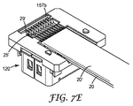
あるいは、オーガナイザ基部152は、第1フロア区分に隣接して配設された第1入れ子区分157aを含み得る。第1入れ子区分は、図7Aに図示されるように、代表的な高速ケーブル20の複数のワイヤ25の終端部上に配設された端子アンカー29を受容するように構成される。同様に、オーガナイザ基部152は、第2フロア区分155に隣接して配設された第2入れ子区分157bを含み得る。第2入れ子区分は、図7Eに図示されるように、代表的な高速ケーブル20’の複数のワイヤ25’の終端部上に配設された端子アンカー29’を受容するように構成される。少なくとも1つの態様では、代表的な高速ケーブル20、20の複数のワイヤの終端部上に配設された端子アンカー29、29’は、代表的なケーブルアセンブリ内で終端された代表的なケーブルを固定し、かつその歪み緩和を提供する。
Alternatively, the
オーガナイザ基部152は、第1フロア区分154に沿って、及び中央トラフ153の側壁部153aに対して平行に延びる複数の第1の溝154aと、オーガナイザ基部を通る複数の第1開口部154bとを含む。接続基部内に配設された第1接触子に対して各第1ワイヤを位置付けるため、各第1開口部154bは異なる第1の溝154aに対応し、異なる第1の溝154aと整列している。代表的な態様では、各第1の溝154aは、中央トラフの側壁部153aに対して実質的に平行であり得る。実質的に平行な溝部は、コネクタアセンブリ内の接触子とほぼ同じピッチを有する高速ケーブルのワイヤを受容するように構成される。別の代表的な態様では、第1の溝は、高速ケーブルからのワイヤを受容するために漏斗形状で配設され得、ワイヤのピッチはコネクタアセンブリ内の接触子のピッチ超であるが、一部又は全部のワイヤを手動で整列させる必要がある場合がある。
The
ケーブルコネクタ102の代表的な実施形態は、ワイヤの2つのセット(すなわち、第1ワイヤ25及び第2ワイヤ25’)を、オフセットの構成で終端させるように構成される。これを可能にするために、オーガナイザ基部152は、第2フロア区分155と、中央トラフ153の閉鎖端部に隣接して配置された第2入れ子区分157bと間に延びる複数の第2の溝155aを更に含み得る。各第2の溝は、中央トラフ153の側壁部153aに対して実質的に平行であり得、及び図4Bに示されるように、複数の第2ワイヤ25’を、接続基部内に配設された第2接触子140に対して位置付けることができる。各第2の溝は、オーガナイザ基部152を通る第2開口部155bを含む。各第2開口部155bは、異なる第2の溝155aに対応し、異なる第2の溝155aと整列する。実質的に平行な第2の溝155aは、高速ケーブル20’からの複数の第2ワイヤ25’を受容し、かつこれらを、ケーブルオーガナイザの第2開口部を通って延びる第2接触子の第2末端部分144と整列させるように構成される。代表的なケーブルオーガナイザ150は、第2高速ケーブルの複数の第2ワイヤがコネクタアセンブリ内の第2接触子とほぼ同じピッチを有するように設計される。オーガナイザに設計は、接触子基部内に配設された接触子よりも、より微細な及びより粗いピッチのいずれかを有するワイヤを受容するように修正され得、これらは本開示の範囲であると考えられる。
An exemplary embodiment of
上記のように、中央チャネルの閉鎖端部に隣接して配設された第2入れ子区分157bは、図7D及び7Eに図示されるように、代表的な第2高速ケーブル20’の複数のワイヤの終端部上に配設された端子アンカー29’を受容するように構成される。
As described above, the
端子アンカー29’は、第2高速ケーブル20’をケーブルオーガナイザ150内に固定し、ケーブルコネクタ102において終端された第2第2高速ケーブル20’の歪み緩和を提供するのに役立つ。
The
したがって、第1の溝は、概ね第1深さの第1平面内に存在し、及び第2の溝は、概ね第2深さの第2平面内に存在し、かつ第1平面の溝部からオフセットしている。1つの代表的に態様では、第1及び第2開口部は、同じ平面内に存在し得る。 Thus, the first groove is generally in the first plane at the first depth, and the second groove is in the second plane at the second depth and from the groove portion of the first plane. It is offset. In one exemplary aspect, the first and second openings can be in the same plane.
1つの代表的な態様では、複数の第1の溝は、ケーブルオーガナイザの基部内に配設された複数の第2の溝と整列し得る。第1の溝は、中央トラフ内の第1深さで配設され得、第2の溝は、中央トラフ内の第2深さで配設され得る。これにより、コネクタアセンブリの長さを増大させずに、電気接続密度は高められ得る。代表的な態様では、ケーブルコネクタ102は、図4Bに示されるように、2つの別個の高速ケーブル内のワイヤ25、25’を終端させるために使用され得る一方、別の態様では、ケーブルコネクタは、2つの平行なワイヤ列を含む高速ケーブル内のワイヤを終端するために使用され得る。あるいは、ケーブルオーガナイザは、複数のケーブル内のワイヤを所定の段上に収容する十分な数の接触子が存在する限り、各段上に(それぞれの深さで)配設される複数のより小さい高速ケーブルを収容し得る。
In one exemplary aspect, the plurality of first grooves may be aligned with the plurality of second grooves disposed within the base of the cable organizer. The first groove may be disposed at a first depth within the central trough, and the second groove may be disposed at a second depth within the central trough. This can increase the electrical connection density without increasing the length of the connector assembly. In an exemplary aspect,
代替的な実施形態では、ケーブルオーガナイザ内の溝は、高速ケーブルを収容するために千鳥配置を有し得、ここで、導体は千鳥配置で配置されている、又は接続基部内に配設された接触子が千鳥配置で配設されている。 In an alternative embodiment, the grooves in the cable organizer may have a staggered arrangement to accommodate high speed cables, where the conductors are arranged in a staggered arrangement or disposed within the connection base. The contacts are arranged in a staggered arrangement.
また、本願では、代表的なケーブルコネクタ102は、複数列の接触子を有するように(すなわち、第1接触子130及び第2接触子140)記載されているが、代表的ケーブルアセンブリの実施形態は、代表的なケーブルコネクタが、絶縁ハウジングと、少なくとも接触子の一部分がプリント回路基板上の導電性配線において終端するように適合されているハウジング内に配設された複数の第1接触子と、絶縁ハウジングに取り付けられたケーブルオーガナイザとを含み得るように、単一列の接触子を収容してもよい。各第1接触子は、嵌合コネクタの対応する接触子と電気的接触を形成するための第1嵌合部分と、ハウジング底部に沿って延びる第1末端部分とを有し、第1末端部分はプリント回路基板上の導電性配線において終端するように適合されている。ケーブルオーガナイザは、ハウジング底部に隣接するように配設され、かつ同じ第1方向に沿って延びる複数の第1の溝と複数の第1開口部とを含み、複数の第1接触子の末端部分にアクセスし、各第1の溝内部に配設されたワイヤをこの末端部と接続するように、各第1開口部は異なる第1の溝に対応し、かつ前記異なる第1の溝と並んでいる。
Also, while the
一方、別の実施形態では、代表的なケーブルコネクタは、3列以上の接触子を含み得、及び接触子の列数は、設計選択の問題であると考えられ、したがって、本開示の範囲であると考えられる。 On the other hand, in another embodiment, a typical cable connector may include more than two rows of contacts, and the number of rows of contacts is considered to be a matter of design choice and thus within the scope of this disclosure. It is believed that there is.
有利なことに、ケーブルオーガナイザ150は、ケーブルコネクタ102の接続基部内に収容された接触子との大量はんだ付けプロセスによって、ワイヤの直接終端を可能にする。例えば、各第1ワイヤ25は、接続基部内の各第1接触子130の第1末端部分134において終端され得る。代表的な態様では、ワイヤは、はんだ付け済み接続部を介して第1及び第2接触子において終端される。例えば、ホットバーはんだ付けプロセスが使用され得、これにより、図4Bに図示されるように、ワイヤ25を第1接触子130に同時に接続することが可能になる。同様に、各第2ワイヤ25’は、大量はんだ付けプロセスによって、ケーブルコネクタ102の接続基部内で、各第2接触子140の第2終端部分144において終端され得る。
Advantageously, the
代表的な態様では、接続基部120は、基板対基板コネクタシステムの第2半端部であり得る。したがって、ケーブルオーガナイザ150は、高速ケーブルからのワイヤを、プリント回路基板に元来はんだ付けられるように適合されている接続基部の接触子に直接終端させることが可能である。代表的なケーブルコネクタ内の基板対基板コネクタシステムの一方の半端部を使用することにより、図1及び2に図示されるようなコネクタシステム100などの得られたケーブル対基板接続システムのファインピッチな接続が確実になる。
In an exemplary aspect, the
ケーブルオーガナイザ150には、高速ケーブルの複数のワイヤと、接触子130、140のそれぞれの末端部分134、144とを容易に整列することを可能にする第1の溝154a及び第2の溝155aが設けられているが、ワイヤを、第1の溝154a、及び第2の溝155a内で個別に整列させる必要がある。整列プロセスを簡素化するために、端子アンカー29は、以下により詳細に記載される新しいケーブル準備プロセスによって、高速ケーブル20の複数のワイヤ25の終端部上に形成される。端子アンカーは、終端アンカーが、入れ子区分157a、157bのうちの1つに配置されるときに、隣接するワイヤ間に適切な間隔を設定し、全てのワイヤがケーブルオーガナイザの第1及び第2の溝内に挿入されることを可能にする。端子アンカーは更に止め具又は歪み緩和器具として機能し、長手方向の力がケーブルに適用されるときにケーブルがケーブルオーガナイザから外れるのを防止し、よって得られるコネクタシステム100の信頼性を向上させる。
The
代表的なケーブルコネクタ102は、図7Gに図示されるように、任意の遮断プレート180を更に含み得る。遮断プレートは、中央トラフ135内に配設された裸線に対してEMI遮断を提供するために、ケーブルオーガナイザ150の中央トラフ135の上に配設され得る。任意の遮断プレート180は、遮断プレートの整列開口部182共に接続基部120の整列ポスト128を使用して、ケーブルオーガナイザの頂部上に位置付けら得る。代表的な態様では、遮断プレートは、例えば、銅シート又はアルミニウムシートなどの金属シートから形成され得るが、他の金属も使用され得る。任意の遮断プレートと、接続基部の絶縁ハウジングの周辺に配設された補助的遮断プレート160とを一緒に使用することにより、ケーブルコネクタ内に配設された裸線の周囲に擬似ファラデー箱構造を形成し得る。この遮断は、外部のEMI信号がケーブル対基板アセンブリに侵入し、アセンブリにより形成された高速信号接続に悪影響を及ぼすのを防止するように構成される。遮断プレートは、高速用途又は非常に高密な回路基板設計における電磁干渉の低減に役立ち得る。
The
最終的に、図2に示されるように、最終ケーブルコネクタ102を製造するために、キャップ110は、接続基部120の頂部及びケーブルオーガナイザ150の上にオーバーモールドされ得る。別の態様では、スナップ式のプラスチックキャップが、使用され得る。キャップは、例えば、ポリブチレンテレフタレート(PBT)樹脂、液晶ポリマ(LCP)樹脂、ポリカーボネート樹脂などの成形可能なプラスチック材料から作製され得る。
Finally, as shown in FIG. 2, the
代表的なケーブルアセンブリは、図6A〜6B及び7A〜7Gを参照して以下のように準備され得る。図6A及び6Bは、複数の導体、すなわちワイヤ25を有する高速ケーブル20の準備を図示する。ケーブルは、まずケーブルの終端部に隣接するケーブルジャケット21の一区分を除去することにより準備される。遮断層22(存在する場合)は、ケーブル内のワイヤが露出するように取り除かれ得る。導体上の絶縁コーティング23は、終端部26に隣接する、各ワイヤ25の露出区分を残すように取り除かれる。
An exemplary cable assembly may be prepared as follows with reference to FIGS. 6A-6B and 7A-7G. 6A and 6B illustrate the preparation of a
端子アンカー29は、図6Bに示されるようにワイヤの終端部が端子アンカー内に入るようにワイヤ25の終端部26上に成形される。端子アンカーは、ワイヤの終端部を成形キャビティ内に挿入し、適切な成形材料をキャビティ内に射出し、これに冷却又は硬化のいずれかを行って形成され得、これによりワイヤの終端部が既知のワイヤ間隔の端子アンカー内に固定的に保持される。ワイヤ間隔は、ケーブルオーガナイザの溝部ピッチとほぼ同じである。成形材料は、端子アンカーを形成するための、ワイヤの周囲に射出成形されるLCP樹脂などの熱可塑性樹脂、反応性樹脂、又はエポキシ樹脂などの熱硬化性ポッティング材料から選択され得る。
The
はんだペーストは、ケーブルの設計によって、端子アンカー29とケーブルジャケット21との間の裸線25に、又は各ワイヤ上の絶縁コーティング23に適用される。代表的なはんだペースト材料は、従来のスズ鉛はんだペースト又は、従来の無鉛はんだペーストであり得る。
The solder paste is applied to the
図7A〜7Gを参照して、準備された第1高速ケーブル20は、代表的なコネクタアセンブリの接続部基部120上に取り付けられているケーブルオーガナイザ150内に配置され、これにより、図7Aに示されるように、各第1ワイヤ25は、異なる第1の溝154aに配設され、準備されたケーブル上の端子アンカー29は、ケーブルオーガナイザ内の第1入れ子区分157a内に位置する。
Referring to FIGS. 7A-7G, the prepared first
図4B及び7Bを参照して、第1ワイヤ25は、はんだ付け装置のサーモード290を、はんだペーストがコーティングされた第1ワイヤに接触させるホットバーはんだ付けプロセスによって、第1接触子130(図4B)へと終端させることができる。はんだペーストは融解し、ケーブルオーガナイザの第1開口部内に流入し、第1接触子130の第1末端部分134と接触して、第1ワイヤと第1接触子と間の電気的接触を提供する。
Referring to FIGS. 4B and 7B, the
次に、第1ワイヤ及び第1接触子の間のはんだ接続部は、図7Cに図示されるように、エポキシベースのポッティング材料などの従来のポッティング材料170をケーブルオーガナイザ150の第1フロア区分154に適用することにより、安定化させることができる。ポッティング材料は、二成分材料、UV硬化材料、又は熱硬化材料であり得る。
Next, the solder connection between the first wire and the first contact is made with a
第2高速ケーブル20’は、上記のように準備される。加えて、図7Dに図示されるように、第2ケーブルの第2ワイヤ25’は、ケーブルオーガナイザ150内の第2ケーブルの位置付けを補正するための曲がった領域25aを有し得る。準備された第2高速ケーブル20’は、代表的な接続アセンブリの接続基部120に取り付けられたケーブルオーガナイザ150内に配置され、これにより、各第2ワイヤ25’は、異なる第2の溝155a内に配設され、並びに準備されたケーブル上の端子アンカー29’は、図7Eに図示されるように、ケーブルオーガナイザの第2入れ子区分157b内に位置する。
The second high speed cable 20 'is prepared as described above. In addition, as illustrated in FIG. 7D, the
第2ワイヤ25’は、上記のように、第2接触子140(図4B)に向かって終端され得る。第2ワイヤ及び第2接触子の間のはんだ接続部は、図7Fに図示されるように、ケーブルオーガナイザの中央トラフ153内の残りの空間を従来のポッティング材料172で充填することにより安定化され得る。あるいは、第1ワイヤと第1接触子との間のはんだ接続部、並びに第2ワイヤ及び第2接続詞の間のはんだ接続部は、ケーブルオーガナイザのトラフを従来のポッティング材料で充填し、その材料を硬化することにより同時に安定化され得る。
The second wire 25 'can be terminated toward the second contact 140 (FIG. 4B) as described above. The solder connection between the second wire and the second contact is stabilized by filling the remaining space in the
次に、任意の遮断プレート180は、接続基部の整列ポスト128が、遮断プレートの整列開口部182と嵌合して、ケーブルコネクタ102内に収容されている接続部に追加のEMI保護を提供するように、ケーブルオーガナイザ150の頂部上に配置され得る。
The
最終的に、図2に示されるように、最終ケーブルコネクタ102を製造するために、キャップ110は、接続基部120の頂部及びケーブルオーガナイザの上にオーバーモールドされ得る。
Finally, as shown in FIG. 2, to produce the
上記のコネクタアセンブリは、従来の基板対基板ソケットコネクタに基づいているが、技術及び教示は、従来のプラグ型基板対基板コネクタにも容易に適用され得、並びに図8及び9との関連において簡易に説明される。 Although the connector assembly described above is based on a conventional board-to-board socket connector, the techniques and teachings can be readily applied to conventional plug-type board-to-board connectors and are simple in the context of FIGS. Explained.
図8及び9は、ケーブル対基板コネクタシステム300の別の代表的な実施形態を示す。ケーブル対基板コネクタシステム300は、(PCB 5に取り付けられた状態の)基板に取り付けられたソケット型コネクタ400と嵌合するプラグ型ケーブルコネクタ302を含む。ケーブルコネクタ302は、第1接触子330及び第2接触子340を保持する絶縁ハウジング322を有するプラグ型接続基部320と、ケーブルオーガナイザ350と、キャップ310とを含む。
FIGS. 8 and 9 illustrate another exemplary embodiment of a cable-to-
代表的な態様では、接続基部320の絶縁ハウジング322、ケーブルオーガナイザ350、及びキャップ310は、例えば、ガラス充填された液晶ポリマ樹脂、ポリブチレンテレフタレート(PBT)樹脂、ポリカーボネート樹脂などの、エンジニアリング樹脂による射出成形法を使用して形成され得る。
In a typical embodiment, the insulating
代表的な態様では、新しい高速ケーブルコネクタは、参照によりその全体が本明細書に組み込まれる、PCT公報第WO2011/025640号、及びPCT出願第PCT/US2012/046481号などに記載の基板対基板接続のプラグ型コネクタ部分を使用し得る。本開示の代表的なケーブルオーガナイザ350を従来のプラグ型基板対基板コネクタ部分に追加することは、元来、プリント回路基板上の導電性配線を終端させるように適合されている接触子を、ファインピッチの高速ケーブルのワイヤ及び導体に接続され得る接触子に変形させる。
In representative aspects, the new high-speed cable connector is a board-to-board connection as described in PCT Publication No. WO2011 / 025640 and PCT Application No. PCT / US2012 / 046481, which are incorporated herein by reference in their entirety. Plug-type connector portions can be used. Adding the
接続基部320は、複数の第1接触子330及び複数の第2接触子を保持するように構成された絶縁ハウジング322を含み得る。絶縁ハウジング322は、ハウジング基部327及びこの基部から垂直に延びる中央壁部326を含む。中央壁部326は、第1側部と第2側部を有し、これらそれぞれは、中央壁部内に形成された複数の接触子チャネルを含み得る。
The
ハウジング基部327は、ハウジング基部の外側表面内に形成された複数の接触子チャネルを有し得る。各接触子チャネルは、各接触子チャネルの底部内のハウジング基部を通る接触子開口部を有し得、これにより、第1及び第2接触子の一部分を、ハウジング基部を通って、中央壁部326の第1及び第2側部内に配設された対応する接触子チャンネル内に入って延びるように、通過させることが可能になる。
The
第1接触子330及び第2接触子340は、概ね「L」字形状であり得る。各第1及び第2接触子は、中央壁部326の第1側部及び第2側部内それぞれに形成された接触子チャネル内に配設された嵌合部分(図示せず)を含み、これは、嵌合コネクタの対応する接触子とハウジング基部327の外側表面内に形成された接触子チャネル内に配設された末端部分334、344と電気的接触を形成するためである。元来、基板対基板接続システム内のプリント回路基板上の導電性配線において終端するように適合されていた末端部分334、344は、ケーブルオーガナイザ350がハウジング基部327の外側表面に隣接するように配置されるときに、ケーブル対基板接続システム内のワイヤにおいて終端するように適合され得る。したがって、代表的なケーブル対基板コネクタでは、各末端部分334、344は、高速ケーブル20、20’からのワイヤ25、25’を終端するのに使用され得る。
The
ケーブルオーガナイザ350は、ケーブルオーガナイザ150と概ね類似である。ケーブルオーガナイザ350は、1つ以上の高速ケーブル20、20’からのワイヤ25、25’と、接続基部内に配設された接触子330、340とを整列させるのに役立つプラグ型接続基部320に取り付けられ得る。具体的には、接続基部320は、ケーブルオーガナイザを通るように配設された整列孔358と嵌合する1つ以上の整列ポスト328を含み得る。図に示された代表的な態様では、整列ポスト328及び対応する整列孔358は、接続基部上にケーブルオーガナイザを位置付けるのに役立つD字形状を有する。しかしながら、例えば、正方形ポスト及び孔、円筒形ポスト及び孔などの別の形状が可能であり、整列ポスト及び対応する整列孔の形状は、本明細書で上記の代表的なケーブル対基板コネクタシステムに関して制限するとは見なされない。
加えて、ケーブルオーガナイザ350は、ケーブルオーガナイザを接続基部320に取り付けるために、ケーブルオーガナイザ基部の下部表面から延びる複数のラッチアーム359を有し得るオーガナイザ基部352を含む。ラッチアーム359は、接続基部320を係合し、ケーブルオーガナイザを接続基部に固定する有刺突出部を含み得る。
In addition, the
ケーブルオーガナイザ350のオーガナイザ基部352は、オーガナイザ基部352の上部表面351内に形成された中央トラフ353を含む。1つの代表的な態様では、中央トラフ353は、中央トラフの開口端部から中央トラフの閉鎖端部までの深さにおいて変化し得る。オーガナイザ基部は、ワイヤを第1接触子330及び第2接触子340それぞれと整列するように位置付けるための中央トラフ内に配設された複数の第1の溝354及び第2の溝355を更に含む。各第1及び第2の溝は、オーガナイザ基部を通る第1及び第2接触子の末端部分334、344へのアクセスを可能にする、オーガナイザ基部を通る開口部を有し得る。図9に図示される代表的な実施形態では、ケーブルオーガナイザ350内に配設されたワイヤのピッチは、接続基部320内に配設された隣接する接触子間のピッチとほぼ同じである。
The
ケーブルオーガナイザ350は、代表的な高速ケーブル20、20の複数のワイヤ25、25’の端末部上に配設された端子アンカー29、29’を受容するための、第1の溝354及び第2の溝355のそれぞれに隣接するように配設された入れ子式区分357を含み得る。端子アンカー29、29’は、代表的なケーブルコネクタ302内で終端された代表的なケーブルを固定し、及び代表的なケーブルコネクタ302内で終端された代表的なケーブルの歪み緩和を提供する。
The
高速ケーブル20、20’は、ケーブルの準備及びケーブルコネクタ302への終端に関して上記されたのと同様な方法で、代表的なケーブルコネクタ302に対して準備され及び終端され得る。
The
本明細書に記載されたように、本発明は、ファインピッチのフラットリボンケーブルを従来の基板対基板型のコネクタ部分のソルダーテイルに直接終端させる手段を提供する。加えて、本開示の代表的なケーブルオーガナイザは、はんだ付けプロセスを単純化し及びそのプロセスの速度を速めることにより、接触子を有するワイヤを代表的なコネクタアセンブリ内に配置することと、終端することとを同時に行うことを可能にして、全体的な製造コストを削減することに役立ち得る。加えて、ホットバーはんだ付けプロセスを用いることにより、代表的なケーブルコネクタのはんだ付けされた接続部の一貫性、品質及び均一性が向上する。 As described herein, the present invention provides a means for directly terminating a fine pitch flat ribbon cable to a solder tail of a conventional board to board connector section. In addition, the exemplary cable organizer of the present disclosure places and terminates wires with contacts in the exemplary connector assembly by simplifying and speeding up the soldering process. Can be performed simultaneously to help reduce overall manufacturing costs. In addition, the use of a hot bar soldering process improves the consistency, quality, and uniformity of the soldered connections of typical cable connectors.
以下は、本開示の項目の一覧である。
項目1は、コネクタアセンブリであって、
絶縁ハウジングと、
ハウジング内に配設された複数の第1接触子であって、各第1接触子は、
嵌合コネクタの対応する接触子と電気的接触を形成するための第1嵌合部分、及び、
ハウジング底部に沿って延び、かつプリント回路基板上の導電性配線において終端するように適合されている第1末端部分を含む、第1接触子と、
複数の第1ワイヤを含む第1ケーブルであって、各第1ワイヤは異なる第1末端部分に対応し、かつ異なる第1末端部分において終端される、第1ケーブルと、を含む。
The following is a list of items of the present disclosure.
Item 1 is a connector assembly,
An insulating housing;
A plurality of first contacts disposed in the housing, wherein each first contact is
A first mating portion for making electrical contact with a corresponding contact of the mating connector; and
A first contact including a first end portion extending along the bottom of the housing and adapted to terminate in conductive traces on the printed circuit board;
A first cable including a plurality of first wires, each first wire corresponding to a different first end portion and terminated at a different first end portion.
項目2は、項目1のコネクタアセンブリであって、ハウジング底部に配設され、及び同じ第1方向に沿って延びる複数の第1の溝と複数の第1開口部とを含むケーブルオーガナイザを更に含み、各第1開口部は、異なる第1の溝に対応し、かつ異なる第1の溝と並んでおり、各第1ワイヤは、異なる第1の溝に対応し、かつ異なる第1の溝内に配置され、第1の溝は、第1の溝に対応する第1開口部を通る第1ワイヤに対応する第1末端部分において終端される。 Item 2 is the connector assembly of item 1, further comprising a cable organizer disposed at the bottom of the housing and including a plurality of first grooves and a plurality of first openings extending along the same first direction. Each first opening corresponds to a different first groove and is aligned with a different first groove, and each first wire corresponds to a different first groove and in a different first groove And the first groove is terminated at a first end portion corresponding to the first wire passing through the first opening corresponding to the first groove.
項目3は、項目2のコネクタアセンブリであり、第1ケーブルは、各第1ワイヤの一部分にわたって形成された端子アンカーを更に含み、端子アンカーは、ケーブル内の複数のワイヤと垂直な方向に延びる、ケーブルオーガナイザの第1入れ子区分内に配置される。 Item 3 is the connector assembly of item 2, wherein the first cable further includes a terminal anchor formed over a portion of each first wire, the terminal anchor extending in a direction perpendicular to the plurality of wires in the cable. Located in the first nested section of the cable organizer.
項目4は、項目2のコネクタアセンブリであり、ケーブルオーガナイザ内の中央トラフの上に位置付けられた遮断プレートを更に含む。 Item 4 is the connector assembly of item 2, further comprising a blocking plate positioned over a central trough in the cable organizer.
項目5は、項目2のコネクタアセンブリであり、絶縁ハウジング及びケーブルオーガナイザの一部分の上に配設されたキャップを更に含む。
項目6は、項目2のコネクタアセンブリであり、ケーブルオーガナイザは、第1方向に沿って延びる第2の溝と複数の第2開口部とを更に含み、各第2開口部は、異なる第2の溝に対応し、かつ異なる第2の溝と並んでおり、各第2ワイヤは、異なる第2の溝と対応し、かつ異なる第2の溝内に配置され、第2のワイヤは、第2の溝に対応する第2開口部を通る第2ワイヤに対応する第2末端部分において終端される。 Item 6 is the connector assembly of item 2, wherein the cable organizer further includes a second groove extending along the first direction and a plurality of second openings, each second opening having a different second Corresponding to the grooves and aligned with different second grooves, each second wire corresponding to a different second groove and disposed in a different second groove, the second wires being second Terminated at the second end portion corresponding to the second wire through the second opening corresponding to the groove.
項目7は、コネクタアセンブリであり、
絶縁ハウジングと、
絶縁ハウジング内に配設された複数の第1接触子であって、各第1接触子は、
嵌合コネクタの対応する接触子と電気的接触を形成するための第1嵌合部分、及び、
ハウジング底部に沿って第1嵌合部分からハウジングの第1側部に向かって延び、かつプリント回路基板上の導電性配線において終端するように適合されている第1末端部分を含む、第1接触子と、
ハウジング内に配設された複数の第2接触子であって、各第2接触子は、
嵌合コネクタに対応する接触子と電気的接触を形成するための第2嵌合部分、及び、
ハウジング底部に沿って第2嵌合部分からハウジングの第2側部に向かって延びる第2末端部分であって、第2側部は、第1側部とは反対側であり、第2嵌合部分は、プリント回路基板上の導電性配線において終端するように適合されている、第2末端部分、を含む、第2接触子と、
複数の第1ワイヤであって、各第1ワイヤは、異なる第1末端部分に対応し、かつ異なる第1末端部分において終端している、複数の第1ワイヤと、
複数の第2ワイヤであって、各第2ワイヤは、異なる第2末端部分に対応し、かつ異なる第2末端部分において終端している、複数の第2ワイヤと、を含む。
Item 7 is a connector assembly,
An insulating housing;
A plurality of first contacts disposed in the insulating housing, wherein each first contact is
A first mating portion for making electrical contact with a corresponding contact of the mating connector; and
A first contact that includes a first end portion that extends from a first mating portion along the bottom of the housing toward a first side of the housing and that is adapted to terminate in conductive traces on the printed circuit board. With the child,
A plurality of second contacts disposed in the housing, each second contact being
A second mating portion for making electrical contact with a contact corresponding to the mating connector; and
A second end portion extending from the second fitting portion toward the second side of the housing along the bottom of the housing, wherein the second side is opposite to the first side, and the second fitting A second contact including a second end portion adapted to terminate in conductive traces on the printed circuit board;
A plurality of first wires, each first wire corresponding to a different first end portion and terminating at a different first end portion;
A plurality of second wires, each second wire corresponding to a different second end portion and terminating at a different second end portion.
項目8は、項目7のコネクタアセンブリであり、ハウジング底部に配設されたケーブルオーガナイザを更に含み、ケーブルオーガナイザは、
同じ第1方向に沿って延びる複数の第1の溝及び複数の第1開口部であって、各第1開口部は、異なる第1の溝に対応し、かつ異なる第1の溝と並んでおり、各第1ワイヤは、異なる第1の溝と対応し、かつ異なる第1の溝に配置され、第1ワイヤは、第1の溝に対応する第1開口部を通る第1ワイヤに対応する第1末端部分において終端している、複数の第1の溝及び複数の第1開口部と、
第1に沿って延びる複数の第2の溝及び複数の第2開口部とであって、各第2開口部は、異なる第2の溝に対応し、かつ異なる第2の溝と並んでおり、各第2ワイヤは、異なる第2の溝と対応し、かつ異なる第2の溝に配置され、第2ワイヤは、第2の溝に対応する第2開口部を通る第2ワイヤに対応する第2末端部分において終端している、複数の第2の溝及び複数の第2開口部と、を含む。
Item 8 is the connector assembly of item 7, further comprising a cable organizer disposed at the bottom of the housing, the cable organizer comprising:
A plurality of first grooves and a plurality of first openings extending along the same first direction, wherein each first opening corresponds to a different first groove and is aligned with a different first groove. And each first wire corresponds to a different first groove and is disposed in a different first groove, the first wire corresponding to the first wire passing through the first opening corresponding to the first groove. A plurality of first grooves and a plurality of first openings terminating in a first end portion that
A plurality of second grooves and a plurality of second openings extending along the first, wherein each second opening corresponds to a different second groove and is aligned with a different second groove , Each second wire corresponds to a different second groove and is arranged in a different second groove, the second wire corresponding to a second wire passing through a second opening corresponding to the second groove. A plurality of second grooves and a plurality of second openings that terminate in the second end portion.
項目9は、項目8のコネクタアセンブリであり、第1の溝は、同じ第1平面に概ね位置し、及び第2の溝は、第1平面に対してオフセットしている同じ第2平面に概ね位置する。 Item 9 is the connector assembly of item 8, wherein the first groove is generally located in the same first plane and the second groove is generally in the same second plane that is offset relative to the first plane. To position.
項目10は、項目8のコネクタアセンブリであり、ケーブルオーガナイザの第1の溝及び第2の溝は、互いに整列している。 Item 10 is the connector assembly of item 8, wherein the first and second grooves of the cable organizer are aligned with each other.
項目11は、項目8のコネクタアセンブリであり、ケーブルオーガナイザの第1の溝及び第2の溝は、千鳥配線になっている。 Item 11 is the connector assembly of item 8, and the first and second grooves of the cable organizer are staggered wiring.
項目12は、項目8のコネクタアセンブリであり、第1及び第2開口部は、同じ平面内に概ね位置する。 Item 12 is the connector assembly of item 8, wherein the first and second openings are generally located in the same plane.
項目13は、項目7のコネクタアセンブリであり、複数の第1ワイヤは、第1ケーブル内に収容され、複数の第2ワイヤは、第2ケーブル内に収容される。 Item 13 is the connector assembly of item 7, wherein the plurality of first wires are housed in the first cable and the plurality of second wires are housed in the second cable.
項目14は、項目7のコネクタアセンブリであり、複数の第1ワイヤ及び複数の第2ワイヤは、第1ケーブル内に収容される。 Item 14 is the connector assembly of item 7, wherein the plurality of first wires and the plurality of second wires are accommodated in the first cable.
項目15は、コネクタアセンブリ用のケーブルオーガナイザであり、このケーブルオーガナイザは、
中央トラフを有するオーガナイザ基部であって、中央トラフは、第1深さで配設された第1フロア区分、第2深さで配設された第2フロア区分、及び第1フロア区分から第2フロア区分まで延びる側壁部を有する、オーガナイザ基部と、
第1フロア区分に沿って延び、中央トラフの側壁部に対して平行である複数の第1の溝であって、第1の溝は複数の第1ワイヤを位置付けるのに役立つ、複数の第1の溝と、
複数の第1開口部であって、各第1開口部は、異なる第1の溝と対応し、かつ異なる第1の溝と整列して、各第1ワイヤが、第1接触子の第1末端部によりコネクタアセンブリ内にて終端するようにする、複数の第1開口部と、を含む。
Item 15 is a cable organizer for the connector assembly.
An organizer base having a central trough, wherein the central trough is second from a first floor section disposed at a first depth, a second floor section disposed at a second depth, and a first floor section. An organizer base having side walls extending to the floor section;
A plurality of first grooves extending along the first floor section and parallel to the sidewalls of the central trough, wherein the first grooves serve to position the plurality of first wires; And the groove
A plurality of first openings, each first opening corresponding to a different first groove and aligned with a different first groove, each first wire being a first contact of the first contactor; A plurality of first openings adapted to terminate in the connector assembly by a distal end.
項目16は、項目15のケーブルオーガナイザであり、第2フロア区分に沿って延びる第2の溝を更に含み、各第2の溝は、各第2の溝内に配設され、かつ各第2の溝と整列する第2開口部を含み、第2の溝は、ケーブルオーガナイザ内の複数の第2ワイヤを位置付けるために役立ち、各第2開口部は、各第2ワイヤが第2接触子の第2末端部分によりコネクタアセンブリ内にて終端するようにする。 Item 16 is the cable organizer of item 15, further including a second groove extending along the second floor section, each second groove being disposed within each second groove and each second groove. A second opening that is aligned with the plurality of grooves, the second groove serving to position a plurality of second wires in the cable organizer, each second opening having a second contact with each second wire A second end portion terminates in the connector assembly.
項目17は、項目16のコネクタアセンブリであり、第1の溝は、同じ第1平面に概ね位置し、及び第2の溝は、第1平面に対してオフセットしている同じ第2平面に概ね位置する。 Item 17 is the connector assembly of item 16, wherein the first groove is generally located in the same first plane and the second groove is generally in the same second plane that is offset relative to the first plane. To position.
項目18は、項目16のコネクタアセンブリであり、ケーブルオーガナイザの第1の溝及び第2の溝は、互いに整列している。 Item 18 is the connector assembly of item 16, wherein the first and second grooves of the cable organizer are aligned with each other.
項目19は、項目16のコネクタアセンブリであり、ケーブルオーガナイザの第1の溝及び第2の溝は、千鳥配線に適合されている。 Item 19 is the connector assembly of item 16, wherein the first and second grooves of the cable organizer are adapted for staggered wiring.
項目20は、項目16のコネクタアセンブリであり、第1及び第2開口部は、同じ平面に概ね位置する。
項目21は、ケーブルコネクタであって、
絶縁ハウジングと、
ハウジング内に配設された複数の第1接触子であって、各第1接触子は、
嵌合コネクタの対応する接触子と電気的接触を形成するための第1嵌合部分、及び、
ハウジング底部に沿って延び、かつプリント回路基板上の導電性配線において終端するように適合されている第1末端部分を含む、第1接触子と、
ハウジング底部に配設され、かつ同じ第1方向に沿って延びる複数の第1の溝と複数の第1開口部とを含むケーブルオーガナイザであって、複数の第1接触子の前記末端部分にアクセスし、各第1の溝内部に配設されたワイヤをこの末端部分と接続するように、各第1開口部は異なる第1の溝に対応し、かつ異なる第1の溝と並んでいる、ケーブルオーガナイザと、を含む。
An insulating housing;
A plurality of first contacts disposed in the housing, wherein each first contact is
A first mating portion for making electrical contact with a corresponding contact of the mating connector; and
A first contact including a first end portion extending along the bottom of the housing and adapted to terminate in conductive traces on the printed circuit board;
A cable organizer disposed on the bottom of the housing and including a plurality of first grooves and a plurality of first openings extending along the same first direction, wherein the end portions of the plurality of first contacts are accessed. And each first opening corresponds to a different first groove and is aligned with a different first groove so as to connect the wire disposed within each first groove to this end portion. Including a cable organizer.
項目22は、項目2のケーブルコネクタであり、ケーブルオーガナイザは、第1方向に沿って延びる第2の溝と、複数の第2開口部とを更に含み、複数の第2接触子の末端部分にアクセスし、各第2の溝内部に配設された追加のワイヤをこの末端部と接続するように、各第2開口部は異なる第2の溝に対応し、かつ異なる第2の溝と並んでいる。
項目23は、項目22のコネクタアセンブリであり、第1の溝は、同じ第1平面に概ね位置し、及び第2の溝は、第1平面に対してオフセットしている、同じ第2平面に概ね位置する。
項目24は、項目22のコネクタアセンブリであり、ケーブルオーガナイザの第1の溝及び第2の溝は、互いに整列している。
Item 24 is the connector assembly of
項目25は、項目22のコネクタアセンブリであり、ケーブルオーガナイザの第1の溝及び第2の溝は、千鳥配線を有し得る。
以上、好適な実施形態の説明を目的として特定の実施形態を本明細書に図示、説明したが、同様の目的を達成することが予想される広範な代替的及び/又は同等の実行形態を、本発明の範囲を逸脱することなく、図示及び説明された特定の実施形態に置き換えることができる点が、当業者には認識されるであろう。機械、電気機械、及び電気分野における当業者であれば、本発明が非常に広範な実施形態で実施され得る点は容易に認識されるところであろう。本出願は、本明細書で検討した好ましい実施形態のあらゆる適合例又は変形例を網羅することを目的としたものである。したがって、本発明は特許請求の範囲及びその等価物によってのみ限定されることを明記しておく。 Although specific embodiments have been illustrated and described herein for the purpose of illustrating preferred embodiments, a wide variety of alternative and / or equivalent implementations that are expected to achieve similar purposes are described. Those skilled in the art will recognize that the specific embodiments shown and described may be substituted without departing from the scope of the present invention. Those skilled in the mechanical, electromechanical, and electrical arts will readily recognize that the present invention can be implemented in a very wide variety of embodiments. This application is intended to cover any adaptations or variations of the preferred embodiments discussed herein. Therefore, it is noted that this invention is limited only by the claims and the equivalents thereof.
Claims (10)
前記ハウジング内に配設された複数の第1接触子であり、各第1接触子は、
嵌合コネクタの対応する接触子と電気的接触を形成するための第1嵌合部分、及び、
ハウジング底部に沿って延び、かつプリント回路基板上の導電性配線において終端するように適合されている第1末端部分を含む、第1接触子と、
複数の第1ワイヤを含む第1ケーブルであり、各第1ワイヤは、異なる第1末端部分に対応し、かつ前記異なる第1末端部分において終端している、第1ケーブルと、を含む、コネクタアセンブリ。 An insulating housing;
A plurality of first contacts disposed in the housing, wherein each first contact is
A first mating portion for making electrical contact with a corresponding contact of the mating connector; and
A first contact including a first end portion extending along the bottom of the housing and adapted to terminate in conductive traces on the printed circuit board;
A first cable including a plurality of first wires, each first wire corresponding to a different first end portion and terminating at the different first end portion. assembly.
前記ハウジング内に配設された複数の第1接触子であり、各第1接触子は、
嵌合コネクタの対応する接触子と電気的接触を形成するための第1嵌合部分、及び、
ハウジング底部に沿って前記第1嵌合部分から前記ハウジングの第1側部に向かって延び、かつプリント回路基板上の導電性配線において終端するように適合されている第1末端部分、を含む、第1接触子と、
前記ハウジング内に配設された複数の第2接触子であり、各第2接触子は、
嵌合コネクタの対応する接触子と電気的接触を形成するための第2嵌合部分、及び、
前記ハウジング底部に沿って前記第2嵌合部分から前記ハウジングの第2側部に向かって延びる第2末端部分であり、前記第2側部は、前記第1側部とは反対側にあり、前記第2嵌合部分は、プリント回路基板上の導電性配線において終端するように適合されている、第2末端部分、を含む、第2接触子と、
複数の第1ワイヤであり、各第1ワイヤは、異なる第1末端部分に対応し、かつ前記異なる第1末端部分において終端している、複数の第1ワイヤと、
複数の第2ワイヤであり、各第2ワイヤは、異なる第2末端部分に対応し、かつ前記異なる第2末端部分において終端している、複数の第2ワイヤと、を含む、コネクタアセンブリ。 An insulating housing;
A plurality of first contacts disposed in the housing, wherein each first contact is
A first mating portion for making electrical contact with a corresponding contact of the mating connector; and
A first end portion extending from the first mating portion along the bottom of the housing toward the first side of the housing and adapted to terminate in conductive wiring on a printed circuit board; A first contact;
A plurality of second contacts disposed in the housing, each second contact being
A second mating portion for making electrical contact with a corresponding contact of the mating connector; and
A second end portion extending from the second fitting portion toward the second side of the housing along the bottom of the housing, the second side being on the opposite side of the first side; The second mating portion includes a second end portion adapted to terminate in conductive wiring on the printed circuit board; and a second contact portion;
A plurality of first wires, each first wire corresponding to a different first end portion and terminating at the different first end portion;
A plurality of second wires, each second wire corresponding to a different second end portion and terminating at the different second end portion.
同じ第1方向に沿って延びる複数の第1の溝及び複数の第1開口部であり、各第1開口部は、異なる第1の溝に対応し、かつ前記異なる第1の溝と並んでおり、各第1ワイヤは、異なる第1の溝と対応し、かつ前記異なる第1の溝内に配置され、前記第1ワイヤは、前記第1の溝に対応する前記第1開口部を通る前記第1ワイヤに対応する前記第1末端部分において終端している、複数の第1の溝及び複数の第1開口部と、
前記第1方向に沿って延びる複数の第2の溝及び複数の第2開口部であり、各第2開口部は、異なる第2の溝に対応し、かつ前記異なる第2の溝と並んでおり、各第2ワイヤは、異なる第2の溝と対応し、かつ前記異なる第2の溝内に配置され、前記第2ワイヤは、前記第2の溝に対応する前記第2開口部を通る前記第2ワイヤに対応する前記第2末端部分において終端している、複数の第2の溝及び複数の第2開口部と、を含む、請求項4に記載のコネクタアセンブリ。 The cable organizer further includes a cable organizer disposed on the bottom of the housing,
A plurality of first grooves and a plurality of first openings extending along the same first direction, each first opening corresponding to a different first groove and aligned with the different first grooves; And each first wire corresponds to a different first groove and is disposed in the different first groove, and the first wire passes through the first opening corresponding to the first groove. A plurality of first grooves and a plurality of first openings terminating in the first end portion corresponding to the first wire;
A plurality of second grooves and a plurality of second openings extending along the first direction, each second opening corresponding to a different second groove and aligned with the different second grooves. Each second wire corresponds to a different second groove and is disposed in the different second groove, and the second wire passes through the second opening corresponding to the second groove. The connector assembly of claim 4, comprising a plurality of second grooves and a plurality of second openings that terminate at the second end portion corresponding to the second wire.
中央トラフを有するオーガナイザ基部であり、前記中央トラフは、第1深さで配設された第1フロア区分、第2深さで配設された第2フロア区分、並びに前記第1フロア区分及び前記第2フロア区分から延びる側壁部を有する、オーガナイザ基部と、
前記第1フロア区分に沿って延び、かつ前記中央トラフの前記側壁部に対して平行である複数の第1の溝であり、前記第1の溝は、複数の第1ワイヤを位置付けるのに役立つ、複数の第1の溝と、
複数の第1開口部であり、各第1開口部は、異なる第1の溝と対応し、かつ前記異なる第1の溝と整列して、各第1ワイヤが第1接触子の第1末端部分により前記コネクタアセンブリ内にて終端するようにする、複数の第1開口部と、を含む、ケーブルオーガナイザ。 A cable organizer for a connector assembly,
An organizer base having a central trough, wherein the central trough includes a first floor section disposed at a first depth, a second floor section disposed at a second depth, and the first floor section and the An organizer base having a side wall extending from the second floor section;
A plurality of first grooves extending along the first floor section and parallel to the side wall portion of the central trough, the first grooves serving to position a plurality of first wires; A plurality of first grooves;
A plurality of first openings, each first opening corresponding to a different first groove and aligned with the different first groove, each first wire being a first end of the first contact A cable organizer comprising: a plurality of first openings adapted to terminate in the connector assembly by a portion;
前記ハウジング内に配設された複数の第1接触子であり、各第1接触子は、
嵌合コネクタの対応する接触子と電気的接触を形成するための第1嵌合部分、及び、
ハウジング底部に沿って延び、かつプリント回路基板上の導電性配線において終端するように適合されている第1末端部分を含む、第1接触子と、
前記ハウジング底部に配設され、かつ同じ第1方向に沿って延びる複数の第1の溝と複数の第1開口部とを含むケーブルオーガナイザであり、前記複数の第1接触子の前記末端部分にアクセスし、各第1の溝内部に配設されたワイヤを前記末端部分と接続するように、各第1開口部は異なる第1の溝に対応し、かつ前記異なる第1の溝と並んでいる、ケーブルオーガナイザと、を含む、ケーブルコネクタ。 An insulating housing;
A plurality of first contacts disposed in the housing, wherein each first contact is
A first mating portion for making electrical contact with a corresponding contact of the mating connector; and
A first contact including a first end portion extending along the bottom of the housing and adapted to terminate in conductive traces on the printed circuit board;
A cable organizer that includes a plurality of first grooves and a plurality of first openings that are disposed on the bottom of the housing and extend along the same first direction, and is provided at the end portion of the plurality of first contacts. Each first opening corresponds to a different first groove and is aligned with the different first groove so as to access and connect a wire disposed within each first groove to the end portion. A cable organizer, including a cable connector.
Applications Claiming Priority (3)
| Application Number | Priority Date | Filing Date | Title |
|---|---|---|---|
| US201261739463P | 2012-12-19 | 2012-12-19 | |
| US61/739,463 | 2012-12-19 | ||
| PCT/US2013/073458 WO2014099405A1 (en) | 2012-12-19 | 2013-12-06 | Cable-to-board connector |
Publications (1)
| Publication Number | Publication Date |
|---|---|
| JP2016501437A true JP2016501437A (en) | 2016-01-18 |
Family
ID=49841848
Family Applications (1)
| Application Number | Title | Priority Date | Filing Date |
|---|---|---|---|
| JP2015549441A Withdrawn JP2016501437A (en) | 2012-12-19 | 2013-12-06 | Cable to board connector |
Country Status (6)
| Country | Link |
|---|---|
| US (1) | US10581189B2 (en) |
| EP (1) | EP2936618A1 (en) |
| JP (1) | JP2016501437A (en) |
| KR (1) | KR20150096480A (en) |
| CN (1) | CN104871372B (en) |
| WO (1) | WO2014099405A1 (en) |
Families Citing this family (14)
| Publication number | Priority date | Publication date | Assignee | Title |
|---|---|---|---|---|
| US10581189B2 (en) * | 2012-12-19 | 2020-03-03 | 3M Innovative Properties Company | Cable-to-board connector |
| US9647366B1 (en) | 2016-04-12 | 2017-05-09 | Microsoft Technology Licensing, Llc | Connector shielding in an electronic device |
| CN106711723B (en) * | 2017-01-18 | 2023-03-14 | 启东乾朔电子有限公司 | Electrical connector assembly |
| US10386589B2 (en) * | 2017-02-01 | 2019-08-20 | 3M Innovation Properties Company | Hybrid cable-to-board connector |
| US10777334B2 (en) | 2017-12-05 | 2020-09-15 | Aptiv Technologies Limited | Wiring harness assembly having multiple separated conductors embedded within a substrate |
| JP7219018B2 (en) * | 2018-05-18 | 2023-02-07 | モレックス エルエルシー | Connectors, connector assemblies, and circuit devices |
| CN109088197B (en) * | 2018-07-27 | 2022-06-21 | 富士康(昆山)电脑接插件有限公司 | Electric connector assembly and electric connector system |
| FI3627635T3 (en) * | 2018-09-19 | 2023-03-22 | Connecting element, module connection, circuit board arrangement and method for fabrication of a connecting element | |
| TWM609115U (en) * | 2019-11-29 | 2021-03-11 | 大陸商東莞立訊技術有限公司 | Terminal module |
| US11381017B2 (en) * | 2020-04-14 | 2022-07-05 | Hewlett Packard Enterprise Development Lp | High connector count mating compliance |
| CN113410706B (en) * | 2021-06-25 | 2022-04-01 | 中航光电科技股份有限公司 | Cable connector |
| CN113410715B (en) * | 2021-06-25 | 2022-04-01 | 中航光电科技股份有限公司 | Connector assembly |
| TWI824318B (en) * | 2021-10-14 | 2023-12-01 | 欣興電子股份有限公司 | Circuit board connection structure |
| KR20230106811A (en) | 2022-01-07 | 2023-07-14 | 이승희 | Band type connector |
Family Cites Families (33)
| Publication number | Priority date | Publication date | Assignee | Title |
|---|---|---|---|---|
| US5201664A (en) * | 1992-02-12 | 1993-04-13 | Amp Incorporated | Alignment member for use with surface mount contacts |
| US5664964A (en) * | 1996-04-10 | 1997-09-09 | Ohio Associated Enterprises, Inc. | High density termination system with molded-on strain relief frame, and method |
| JP2002025667A (en) * | 2000-07-11 | 2002-01-25 | Hirose Electric Co Ltd | Connector for flat cable |
| US6273753B1 (en) | 2000-10-19 | 2001-08-14 | Hon Hai Precision Ind. Co., Ltd. | Twinax coaxial flat cable connector assembly |
| US6582252B1 (en) | 2002-02-11 | 2003-06-24 | Hon Hai Precision Ind. Co., Ltd. | Termination connector assembly with tight angle for shielded cable |
| DE60300584T2 (en) | 2002-02-15 | 2006-01-19 | Sumitomo Wiring Systems, Ltd., Yokkaichi | Shielded connector, shielded connector system, contact insert and use thereof |
| CN2588592Y (en) * | 2002-11-23 | 2003-11-26 | 富士康(昆山)电脑接插件有限公司 | Cable connector assembly |
| US6722915B1 (en) * | 2002-12-30 | 2004-04-20 | Tyco Electronics Corporation | Electrical connector for connecting circuit boards to flat flexible cables |
| JP4421427B2 (en) * | 2004-08-31 | 2010-02-24 | 富士通コンポーネント株式会社 | Cable connector for balanced transmission |
| JP2006244731A (en) * | 2005-02-28 | 2006-09-14 | Molex Inc | Terminal and connector using this terminal |
| JP4600245B2 (en) * | 2005-10-31 | 2010-12-15 | ミツミ電機株式会社 | connector |
| CN200959384Y (en) * | 2006-09-13 | 2007-10-10 | 富士康(昆山)电脑接插件有限公司 | Electric connector |
| US7452238B1 (en) | 2007-06-11 | 2008-11-18 | Hon Hai Precision Ind. Co., Ltd. | Cable connector assembly with improved spacer |
| US7462065B1 (en) * | 2007-11-05 | 2008-12-09 | Hon Hai Precision Ind. Co., Ltd. | Method for terminating conductors of a cable to tail portion of contact terminals of ultra fine pitch connector |
| CN101499568B (en) * | 2008-02-01 | 2013-03-13 | 富士康(昆山)电脑接插件有限公司 | Cable connector assembly and method of making same |
| CN201178146Y (en) * | 2008-03-05 | 2009-01-07 | 富士康(昆山)电脑接插件有限公司 | Electric connector and electric connector assembly |
| SG166707A1 (en) * | 2009-06-03 | 2010-12-29 | 3M Innovative Properties Co | Connector |
| EP3261100A1 (en) | 2009-06-19 | 2017-12-27 | 3M Innovative Properties Company | Shielded electrical cable and method of making |
| CN102686181B (en) | 2009-08-27 | 2016-08-10 | 新泽西理工学院 | Integrated fiber Raman spectrum and radio-frequency (RF) ablation |
| SG174642A1 (en) | 2010-03-22 | 2011-10-28 | 3M Innovative Properties Co | Board-to-board connector |
| US8829248B2 (en) | 2010-08-18 | 2014-09-09 | Eastman Chemical Company | Method for recovery and recycle of ruthenium homogeneous catalysts |
| JP5594053B2 (en) * | 2010-10-22 | 2014-09-24 | 第一精工株式会社 | Electrical connector and assembly thereof |
| WO2013012680A1 (en) | 2011-07-15 | 2013-01-24 | 3M Innovative Properties Company | An electrical connector |
| CN102957013A (en) * | 2011-08-18 | 2013-03-06 | 昆山联滔电子有限公司 | Cable plug connector, board terminal socket connector and connector component |
| JP5826565B2 (en) * | 2011-08-31 | 2015-12-02 | 日本航空電子工業株式会社 | connector |
| DE212012000216U1 (en) * | 2011-11-23 | 2014-07-17 | 3M Innovative Properties Company | Locking connector assembly |
| US8894433B2 (en) * | 2012-05-24 | 2014-11-25 | Hon Hai Precision Industry Co., Ltd. | Electrical connector assembly with enhanced blind mating features |
| JP2014093123A (en) * | 2012-10-31 | 2014-05-19 | Tyco Electronics Japan Kk | Flat cable connector |
| US10581189B2 (en) * | 2012-12-19 | 2020-03-03 | 3M Innovative Properties Company | Cable-to-board connector |
| US9426888B2 (en) * | 2013-01-11 | 2016-08-23 | 3M Innovative Properties Company | Substrate for mounting electrical connector |
| US20140206230A1 (en) * | 2013-01-18 | 2014-07-24 | Molex Incorporated | Paddle Card Assembly For High Speed Applications |
| US9466925B2 (en) * | 2013-01-18 | 2016-10-11 | Molex, Llc | Paddle card assembly for high speed applications |
| US9112302B2 (en) * | 2013-05-02 | 2015-08-18 | Hon Hai Precision Industry Co., Ltd. | Electrical connector and assembly thereof |
-
2013
- 2013-12-06 US US14/648,511 patent/US10581189B2/en active Active
- 2013-12-06 EP EP13811330.3A patent/EP2936618A1/en not_active Withdrawn
- 2013-12-06 JP JP2015549441A patent/JP2016501437A/en not_active Withdrawn
- 2013-12-06 KR KR1020157018876A patent/KR20150096480A/en not_active Application Discontinuation
- 2013-12-06 WO PCT/US2013/073458 patent/WO2014099405A1/en active Application Filing
- 2013-12-06 CN CN201380066707.6A patent/CN104871372B/en not_active Expired - Fee Related
Also Published As
| Publication number | Publication date |
|---|---|
| US20150311612A1 (en) | 2015-10-29 |
| EP2936618A1 (en) | 2015-10-28 |
| KR20150096480A (en) | 2015-08-24 |
| WO2014099405A1 (en) | 2014-06-26 |
| CN104871372A (en) | 2015-08-26 |
| CN104871372B (en) | 2018-10-16 |
| US10581189B2 (en) | 2020-03-03 |
Similar Documents
| Publication | Publication Date | Title |
|---|---|---|
| US10581189B2 (en) | Cable-to-board connector | |
| US11189943B2 (en) | I/O connector configured for cable connection to a midboard | |
| US11715914B2 (en) | High speed, high density electrical connector with shielded signal paths | |
| US11757224B2 (en) | High performance cable connector | |
| US11539171B2 (en) | Connector configurable for high performance | |
| US8926377B2 (en) | High performance, small form factor connector with common mode impedance control | |
| US8152568B2 (en) | Cable assembly with new interface | |
| US7909646B2 (en) | Electrical carrier assembly and system of electrical carrier assemblies | |
| US7281950B2 (en) | High speed connectors that minimize signal skew and crosstalk | |
| US11942716B2 (en) | High speed electrical connector | |
| KR20130045388A (en) | Plug connector for differential data transmission | |
| TW200805818A (en) | Boardmount header to cable connector assembly | |
| CN216488672U (en) | Electrical connector with improved contact arrangement | |
| US20240106153A1 (en) | High performance mezzanine connector with low stack height | |
| CN111129808B (en) | Grounding terminal assembly, electric connector and electric connector assembly | |
| KR101528316B1 (en) | Receptacle connector having improved mounting strength | |
| TWM644346U (en) | Electrical connector and related electronic systems |
Legal Events
| Date | Code | Title | Description |
|---|---|---|---|
| A621 | Written request for application examination |
Free format text: JAPANESE INTERMEDIATE CODE: A621 Effective date: 20161111 |
|
| A761 | Written withdrawal of application |
Free format text: JAPANESE INTERMEDIATE CODE: A761 Effective date: 20170821 |