JP2016500534A - Centrifugal pump - Google Patents
Centrifugal pump Download PDFInfo
- Publication number
- JP2016500534A JP2016500534A JP2015537352A JP2015537352A JP2016500534A JP 2016500534 A JP2016500534 A JP 2016500534A JP 2015537352 A JP2015537352 A JP 2015537352A JP 2015537352 A JP2015537352 A JP 2015537352A JP 2016500534 A JP2016500534 A JP 2016500534A
- Authority
- JP
- Japan
- Prior art keywords
- pump
- bearing
- housing
- centrifugal pump
- pump according
- Prior art date
- Legal status (The legal status is an assumption and is not a legal conclusion. Google has not performed a legal analysis and makes no representation as to the accuracy of the status listed.)
- Ceased
Links
Images


Classifications
-
- F—MECHANICAL ENGINEERING; LIGHTING; HEATING; WEAPONS; BLASTING
- F04—POSITIVE - DISPLACEMENT MACHINES FOR LIQUIDS; PUMPS FOR LIQUIDS OR ELASTIC FLUIDS
- F04D—NON-POSITIVE-DISPLACEMENT PUMPS
- F04D13/00—Pumping installations or systems
- F04D13/02—Units comprising pumps and their driving means
- F04D13/06—Units comprising pumps and their driving means the pump being electrically driven
- F04D13/0646—Units comprising pumps and their driving means the pump being electrically driven the hollow pump or motor shaft being the conduit for the working fluid
-
- F—MECHANICAL ENGINEERING; LIGHTING; HEATING; WEAPONS; BLASTING
- F04—POSITIVE - DISPLACEMENT MACHINES FOR LIQUIDS; PUMPS FOR LIQUIDS OR ELASTIC FLUIDS
- F04D—NON-POSITIVE-DISPLACEMENT PUMPS
- F04D29/00—Details, component parts, or accessories
- F04D29/05—Shafts or bearings, or assemblies thereof, specially adapted for elastic fluid pumps
- F04D29/056—Bearings
-
- A—HUMAN NECESSITIES
- A61—MEDICAL OR VETERINARY SCIENCE; HYGIENE
- A61M—DEVICES FOR INTRODUCING MEDIA INTO, OR ONTO, THE BODY; DEVICES FOR TRANSDUCING BODY MEDIA OR FOR TAKING MEDIA FROM THE BODY; DEVICES FOR PRODUCING OR ENDING SLEEP OR STUPOR
- A61M60/00—Blood pumps; Devices for mechanical circulatory actuation; Balloon pumps for circulatory assistance
- A61M60/10—Location thereof with respect to the patient's body
- A61M60/122—Implantable pumps or pumping devices, i.e. the blood being pumped inside the patient's body
- A61M60/165—Implantable pumps or pumping devices, i.e. the blood being pumped inside the patient's body implantable in, on, or around the heart
- A61M60/178—Implantable pumps or pumping devices, i.e. the blood being pumped inside the patient's body implantable in, on, or around the heart drawing blood from a ventricle and returning the blood to the arterial system via a cannula external to the ventricle, e.g. left or right ventricular assist devices
-
- A—HUMAN NECESSITIES
- A61—MEDICAL OR VETERINARY SCIENCE; HYGIENE
- A61M—DEVICES FOR INTRODUCING MEDIA INTO, OR ONTO, THE BODY; DEVICES FOR TRANSDUCING BODY MEDIA OR FOR TAKING MEDIA FROM THE BODY; DEVICES FOR PRODUCING OR ENDING SLEEP OR STUPOR
- A61M60/00—Blood pumps; Devices for mechanical circulatory actuation; Balloon pumps for circulatory assistance
- A61M60/20—Type thereof
- A61M60/205—Non-positive displacement blood pumps
- A61M60/216—Non-positive displacement blood pumps including a rotating member acting on the blood, e.g. impeller
- A61M60/226—Non-positive displacement blood pumps including a rotating member acting on the blood, e.g. impeller the blood flow through the rotating member having mainly radial components
- A61M60/232—Centrifugal pumps
-
- A—HUMAN NECESSITIES
- A61—MEDICAL OR VETERINARY SCIENCE; HYGIENE
- A61M—DEVICES FOR INTRODUCING MEDIA INTO, OR ONTO, THE BODY; DEVICES FOR TRANSDUCING BODY MEDIA OR FOR TAKING MEDIA FROM THE BODY; DEVICES FOR PRODUCING OR ENDING SLEEP OR STUPOR
- A61M60/00—Blood pumps; Devices for mechanical circulatory actuation; Balloon pumps for circulatory assistance
- A61M60/40—Details relating to driving
- A61M60/403—Details relating to driving for non-positive displacement blood pumps
- A61M60/422—Details relating to driving for non-positive displacement blood pumps the force acting on the blood contacting member being electromagnetic, e.g. using canned motor pumps
-
- A—HUMAN NECESSITIES
- A61—MEDICAL OR VETERINARY SCIENCE; HYGIENE
- A61M—DEVICES FOR INTRODUCING MEDIA INTO, OR ONTO, THE BODY; DEVICES FOR TRANSDUCING BODY MEDIA OR FOR TAKING MEDIA FROM THE BODY; DEVICES FOR PRODUCING OR ENDING SLEEP OR STUPOR
- A61M60/00—Blood pumps; Devices for mechanical circulatory actuation; Balloon pumps for circulatory assistance
- A61M60/80—Constructional details other than related to driving
- A61M60/802—Constructional details other than related to driving of non-positive displacement blood pumps
- A61M60/818—Bearings
- A61M60/825—Contact bearings, e.g. ball-and-cup or pivot bearings
-
- A—HUMAN NECESSITIES
- A61—MEDICAL OR VETERINARY SCIENCE; HYGIENE
- A61M—DEVICES FOR INTRODUCING MEDIA INTO, OR ONTO, THE BODY; DEVICES FOR TRANSDUCING BODY MEDIA OR FOR TAKING MEDIA FROM THE BODY; DEVICES FOR PRODUCING OR ENDING SLEEP OR STUPOR
- A61M60/00—Blood pumps; Devices for mechanical circulatory actuation; Balloon pumps for circulatory assistance
- A61M60/80—Constructional details other than related to driving
- A61M60/855—Constructional details other than related to driving of implantable pumps or pumping devices
- A61M60/857—Implantable blood tubes
-
- A—HUMAN NECESSITIES
- A61—MEDICAL OR VETERINARY SCIENCE; HYGIENE
- A61M—DEVICES FOR INTRODUCING MEDIA INTO, OR ONTO, THE BODY; DEVICES FOR TRANSDUCING BODY MEDIA OR FOR TAKING MEDIA FROM THE BODY; DEVICES FOR PRODUCING OR ENDING SLEEP OR STUPOR
- A61M60/00—Blood pumps; Devices for mechanical circulatory actuation; Balloon pumps for circulatory assistance
- A61M60/80—Constructional details other than related to driving
- A61M60/855—Constructional details other than related to driving of implantable pumps or pumping devices
- A61M60/871—Energy supply devices; Converters therefor
- A61M60/873—Energy supply devices; Converters therefor specially adapted for wireless or transcutaneous energy transfer [TET], e.g. inductive charging
-
- F—MECHANICAL ENGINEERING; LIGHTING; HEATING; WEAPONS; BLASTING
- F04—POSITIVE - DISPLACEMENT MACHINES FOR LIQUIDS; PUMPS FOR LIQUIDS OR ELASTIC FLUIDS
- F04D—NON-POSITIVE-DISPLACEMENT PUMPS
- F04D17/00—Radial-flow pumps, e.g. centrifugal pumps; Helico-centrifugal pumps
- F04D17/08—Centrifugal pumps
- F04D17/10—Centrifugal pumps for compressing or evacuating
-
- F—MECHANICAL ENGINEERING; LIGHTING; HEATING; WEAPONS; BLASTING
- F04—POSITIVE - DISPLACEMENT MACHINES FOR LIQUIDS; PUMPS FOR LIQUIDS OR ELASTIC FLUIDS
- F04D—NON-POSITIVE-DISPLACEMENT PUMPS
- F04D29/00—Details, component parts, or accessories
- F04D29/04—Shafts or bearings, or assemblies thereof
- F04D29/046—Bearings
- F04D29/0467—Spherical bearings
-
- A—HUMAN NECESSITIES
- A61—MEDICAL OR VETERINARY SCIENCE; HYGIENE
- A61M—DEVICES FOR INTRODUCING MEDIA INTO, OR ONTO, THE BODY; DEVICES FOR TRANSDUCING BODY MEDIA OR FOR TAKING MEDIA FROM THE BODY; DEVICES FOR PRODUCING OR ENDING SLEEP OR STUPOR
- A61M60/00—Blood pumps; Devices for mechanical circulatory actuation; Balloon pumps for circulatory assistance
- A61M60/10—Location thereof with respect to the patient's body
- A61M60/122—Implantable pumps or pumping devices, i.e. the blood being pumped inside the patient's body
- A61M60/126—Implantable pumps or pumping devices, i.e. the blood being pumped inside the patient's body implantable via, into, inside, in line, branching on, or around a blood vessel
- A61M60/148—Implantable pumps or pumping devices, i.e. the blood being pumped inside the patient's body implantable via, into, inside, in line, branching on, or around a blood vessel in line with a blood vessel using resection or like techniques, e.g. permanent endovascular heart assist devices
Abstract
ヒトの心臓へのインプラント用のポンプは、ハウジング(1)内を通る流路と、その流路に沿った流体の流れを生じさせるためのハウジング内の回転可能なポンプ部材(21)とを有する。ポンプ部材は、上流側ベアリング(32)及び下流側ベアリング(33)においてハウジングに回転可能に結合されている。下流側ベアリングは、ポンプ部材上のベアリング部材(34)と、ハウジング上の相補的なベアリング構造(35)とを備える。このポンプは、前記ポンプ部材の軸(A)に沿ってベアリング構造(35)の位置を微調整するための機械的な調節具(42)を備える。機械的な調節具(42)は好ましくは、軸(A)に沿ったボス部(40)の調節可能な移動用の一つ以上のネジ(42)であり、その調節可能な移動は、ボス部と一体化したプレート部材(41)のたわみ(湾曲)によって許容される。【選択図】図4A pump for implanting a human heart has a flow path through the housing (1) and a rotatable pump member (21) within the housing for creating a fluid flow along the flow path. . The pump member is rotatably coupled to the housing at the upstream bearing (32) and the downstream bearing (33). The downstream bearing comprises a bearing member (34) on the pump member and a complementary bearing structure (35) on the housing. The pump includes a mechanical adjuster (42) for finely adjusting the position of the bearing structure (35) along the axis (A) of the pump member. The mechanical adjuster (42) is preferably one or more screws (42) for adjustable movement of the boss part (40) along the axis (A), the adjustable movement being the boss It is allowed by the deflection (curvature) of the plate member (41) integrated with the part. [Selection] Figure 4
Description
本発明は、遠心力ポンプに関するものである。とりわけ、ヒトの心臓または血管系にインプラント(移植)するのに適した小型化されたポンプに関するものであるが、これに限定するものではない。本発明は、主として心臓系で用いるためのポンプを参照しつつ説明されるが、本発明に従うポンプは他の応用例での使用にも適するものであることは、理解されるであろう。 The present invention relates to a centrifugal pump. In particular, but not exclusively, it relates to a miniaturized pump suitable for implantation into the human heart or vascular system. Although the present invention will be described with reference to a pump primarily for use in the cardiac system, it will be understood that the pump according to the present invention is suitable for use in other applications.
心不全(又は心臓まひ)は、毎年数千人もの死をもたらす世界的に大きな健康問題である。最近まで、進行性心不全を治療的に処理する唯一の方法は、心臓移植あるいは完全な人工心臓の移植によるものだった。残念なことに、ドナーの心臓は需要のごく僅かを満たすことができるに過ぎず、完全な人工心臓は、これらの装置に内在する技術的困難性のために幅広い支持をいまだ得る必要がある。 Heart failure (or heart attack) is a major health problem worldwide that causes thousands of deaths each year. Until recently, the only way to treat progressive heart failure therapeutically was by heart transplantation or a complete artificial heart transplant. Unfortunately, the donor heart can only meet a small demand, and a complete artificial heart still needs to gain broad support due to the technical difficulties inherent in these devices.
心室補助装置(ventricular assist device)(VAD)が、移植装置への橋渡しとして、主として過去10年にわたり支持を集めてきた。その装置は長期間移植され、病気の心臓と共に働いて心臓の出力を促進し、患者を生存状態に保つ、及び/又は、移植を待つ間に生活の質をより良くする。 Ventricular assist devices (VAD) have gained support mainly over the past decade as a bridge to transplant devices. The device is implanted for a long period of time and works with the sick heart to promote cardiac output, keep the patient alive and / or improve the quality of life while waiting for the implant.
これらの装置の使用は、多くのケースで、当該装置が一旦移植されると、心不全が更に進行せず、患者が良好な生活の質を回復することを示した。心臓移植が得られなかった場合でも、患者は、大きな合併症を生じることなくVADを装着した状態で数年間生存している。 The use of these devices has shown in many cases that once the device is implanted, heart failure does not progress further and the patient recovers a good quality of life. Even if a heart transplant is not obtained, the patient is alive for several years with VAD without major complications.
それ故、VADは、心臓移植に代わる実行可能な代替案と考えられ得るものであり、ドナー心臓が入手できそうもない数千人の心不全患者に希望を与えるものである。 Therefore, VAD can be considered a viable alternative to heart transplantation and offers hope to thousands of heart failure patients for whom donor hearts are unlikely to be available.
現時点で、VADをごく日常的に装着することを妨げる主たる理由は、装置を装着するのに必要となる侵襲的な外科手術と、装置自体の高コストにある。 At present, the main reasons that prevent VAD from being worn on a daily basis are the invasive surgical procedures required to wear the device and the high cost of the device itself.
外科手術に関しては、典型的には、胸骨切開、全心肺バイパス、並びに、心臓、胸部大動脈および腹腔への大手術が、VAD装着のために要求される。現在、そのような手術のリスクは、心不全が最も進行した段階にある患者の場合を除いて正当化され得ない。 For surgery, typically sternotomy, total cardiopulmonary bypass, and major surgery to the heart, thoracic aorta and abdominal cavity are required for VAD placement. Currently, the risk of such surgery cannot be justified except in patients with heart failure at the most advanced stage.
現在商業化されている装置は概して構造が複雑であり、その構造のために特別で高価な製造プロセスを必要とする。それ故、それらはコストがかかるものであり、そして、装置を装着するために必要とされる外科手術はまた、長くて厳しい手術であることのために高価である。 Currently commercialized devices are generally complex in structure and require special and expensive manufacturing processes for that structure. Therefore, they are costly and the surgery required to wear the device is also expensive due to being a long and demanding operation.
仮に、VAD又はそれと等価な循環補助装置の長期植込みが、より侵襲性の低い外科手術でもって、つまり腹腔への手術を省くと共に理想的には胸骨切開および心肺バイパスの必要を無くすことでもって達成され、且つ装置のコストが大幅に低減されるならば、そのときには、心不全治療にVADを用いることがもっと広範で日常的なものとなろう。 For example, long-term implantation of a VAD or equivalent circulatory assist device can be achieved with a less invasive surgical procedure, i.e., eliminating the abdominal surgery and ideally eliminating the need for sternotomy and cardiopulmonary bypass. If the cost of the device is greatly reduced, then it would be more extensive and routine to use VAD for heart failure treatment.
より侵襲性の低いVADの移植手術の鍵は、当該装置を、腹腔への手術の必要性を無くしつつ心膜腔内に全体的に移植できるよう可能な限り小さくすることである。更に、全胸骨切開とは対照的に開胸(術)によって移植されるに十分に小さい装置は、このアプローチ(提案)が適切である場合においては有益であろう。 The key to the less invasive VAD transplant operation is to make the device as small as possible so that it can be implanted entirely into the pericardial cavity without the need for surgery on the abdominal cavity. Furthermore, a device that is small enough to be implanted by thoracotomy (surgery) as opposed to a total sternotomy would be beneficial where this approach (suggestion) is appropriate.
外科的リスクを最小化することもまた重要であり、可能であれば改良を加えつつ既存の実績のあるテクニックを使うことは有益である。現在のVADを移植することの実績のある方法は、装置への入口を心室内に存在させ且つ装置の出口を心臓の外に置いた状態で、左心室の頂部(先端)に直接デバイスを取り付けることである。このことは、合併症の可能性を低減する分離流入カニューレ(排管)の必要を除外する。ポンプ(インペラ(羽根車)、モーターなど)の仕組みは、ポンプの設計に応じて、心室のほぼ内側に、心室の壁を横切って、あるいは心室のほぼ外側に存在してもよい。 Minimizing surgical risk is also important, and it is beneficial to use existing, proven techniques with improvements where possible. Current methods of implanting a VAD attach the device directly to the top (tip) of the left ventricle with the entrance to the device in the ventricle and the exit of the device outside the heart That is. This eliminates the need for a separate inflow cannula (exhaust) that reduces the possibility of complications. The mechanism of the pump (impeller, motor, etc.) may exist approximately inside the ventricle, across the ventricular wall, or approximately outside the ventricle, depending on the pump design.
VADの作動効率は、モーター効率およびポンプ効率の適切な組み合わせによって、できる限り高くあるべきである。高い効率は、バッテリ寿命を延ばす、電力ケーブルをより小さくする、及び、インプラント可能な誘導コイルを介したポンプの経皮的な電力供給についての可能性、といったような利益をもたらす。 The operating efficiency of the VAD should be as high as possible by an appropriate combination of motor efficiency and pump efficiency. High efficiency provides benefits such as extending battery life, making power cables smaller, and the potential for transcutaneous power delivery of the pump via an implantable induction coil.
装置の取り付けのための公知で低リスクの外科手術を用いて、ヒトの心臓又は血管系へのインプラントに適した改良型の小型心臓ポンプを開発することへの継続的な要求が存在する。ポンプのベアリング(軸受け)は、作動中における血栓形成の機会を最小化すべく血液によって十分に洗浄されるべきであり、ポンプは、腹腔への外科手術無しで心膜腔内に全体的に移植されるに十分小さくあるべきである。 There is a continuing need to develop improved miniature heart pumps suitable for implantation into the human heart or vascular system using known low-risk surgical procedures for device attachment. The pump bearings (bearings) should be thoroughly flushed with blood to minimize the chance of thrombus formation during operation, and the pump is implanted entirely within the pericardial space without surgery to the abdominal cavity. Should be small enough.
一般論として、例えばヒトの心臓の心室へのインプラントに適したポンプのような、遠心力ポンプは、以下の要素を備えるものとして知られている:即ち、
(a)流体導入口、流体排出口、及び、その導入口と排出口との間に延びる流路を備えたハウジング;並びに、
(b)前記導入口から排出口までの流路に沿った流体の流れを生じさせるべく、前記ハウジング内に軸方向に配置されたインペラを含んでなる回転可能なポンプ部材であって、
当該ポンプ部材は、上流側ベアリング及び下流側ベアリングにおいてハウジングに回転可能に連結されており、下流側ベアリングは、ポンプ部材上のベアリング部材と、ハウジング上の相補的なベアリングシート構造(軸受け座構造)とを備えている、回転可能なポンプ部材。
In general terms, centrifugal pumps, such as pumps suitable for implantation into the ventricle of the human heart, are known to comprise the following elements:
(A) a housing having a fluid inlet, a fluid outlet, and a flow path extending between the inlet and the outlet; and
(B) a rotatable pump member comprising an impeller disposed axially within the housing to cause a fluid flow along a flow path from the inlet to the outlet;
The pump member is rotatably connected to the housing at the upstream bearing and the downstream bearing. The downstream bearing includes a bearing member on the pump member and a complementary bearing seat structure (bearing seat structure) on the housing. And a rotatable pump member.
そのような公知の装置では、ポンプ部材は、上流側及び下流側ベアリングのそれぞれにおいてハウジングに対し回転可能に連結されており、前記回転可能な部材は、ポンプ部材とハウジングとの間に二次流路を区画形成するインペラ側板(インペラ・シュラウド)を有することがあるインペラを含む。 In such known devices, the pump member is rotatably connected to the housing at each of the upstream and downstream bearings, the rotatable member being a secondary flow between the pump member and the housing. It includes an impeller that may have an impeller side plate (impeller shroud) that defines a path.
そのような遠心力ポンプにおいては、上流側及び下流側ベアリングに前記回転可能なポンプ部材を正確にセットする際に、時として問題があるということを見出した。具体的には、上流側ベアリングと下流側ベアリングとの間の軸方向分離(以後「セット長」と言う)があまりにも長いと、回転可能なポンプ部材が使用時に振動しガタつきがちとなり、その一方で、セット長があまりにも短いと、ポンプ部材が回転時に動きにくくなる。どちらの場合も望ましいものではない、というのも、どちらの場合もベアリングの寿命を短くし、極端な場合にはポンプを機能不全に陥らせる。それぞれの部品は非常に小さいから、セット長が「丁度よく」なるように十分な精度を達成することは困難である。 It has been found that such centrifugal pumps sometimes have problems when accurately setting the rotatable pump member on the upstream and downstream bearings. Specifically, if the axial separation between the upstream bearing and the downstream bearing (hereinafter referred to as the “set length”) is too long, the rotatable pump member tends to vibrate during use, causing looseness. On the other hand, if the set length is too short, the pump member is difficult to move during rotation. Neither case is desirable, either because it shortens the life of the bearing and, in extreme cases, causes the pump to malfunction. Since each part is very small, it is difficult to achieve sufficient accuracy so that the set length is “just right”.
本発明によれば、上述のようなタイプの遠心力ポンプが更に、ポンプ部材の軸に沿ったベアリング構造の位置を微調節するための機械的な調節具(例えば、1つ以上のネジのようなもの)を具備する。
その機械的な調節具は、軸に沿ってベアリング部材の方へ向かう、あるいは、軸に沿ってベアリング部材から離れる、ポンプ部材の軸に沿ってのベアリング構造の調節可能な移動のためのものであってもよい。好ましい実施形態では、その調節可能な移動は、ハウジングの一部を形成するプレート部材の湾曲(たわみ)によって許容され、湾曲(たわみ)は、関連性のある機械的な調節具が締め付けられるにつれて生じる。
In accordance with the present invention, a centrifugal pump of the type described above may further include a mechanical adjuster (such as one or more screws) for finely adjusting the position of the bearing structure along the axis of the pump member. A).
The mechanical adjuster is for adjustable movement of the bearing structure along the axis of the pump member, either towards the bearing member along the axis or away from the bearing member along the axis. There may be. In a preferred embodiment, the adjustable movement is allowed by the curvature (deflection) of the plate member that forms part of the housing, which occurs as the associated mechanical adjustment is tightened. .
好ましくは、ベアリングシート(軸受け座)は、ハウジングの一部を形成するプレート部材と一体的であり、好ましい実施態様では、ベアリングシートは、プレート部材と一体化したボス部に設けられている。ここで使用される「ボス部」という用語は、丸い形状の突出部を意味し、それは典型的には円形の断面形状を有しており、その突出部は、それが一体化されている周辺部位よりも厚みがあり、従ってより固いものである。 Preferably, the bearing seat (bearing seat) is integral with a plate member that forms part of the housing, and in a preferred embodiment, the bearing seat is provided on a boss that is integral with the plate member. As used herein, the term “boss” means a round-shaped protrusion, which typically has a circular cross-sectional shape, which is the periphery around which it is integrated. It is thicker than the site and therefore harder.
ここで使用される「下流(側)」という用語は、一次流路における流れ方向に対して定義されている。即ち、一次流路においてハウジングの導入口により近い任意の部位(具体的には、心臓ポンプの場合、ポンプを通じた血流の源により近い部位)が「上流(側)」であると考えられ、導入口と排出口との間の流路(一次流路)を流体がそれに向かって流れるところの任意の部位(例えば、前述の下流側ベアリング)が「下流(側)」であると考えられる。 As used herein, the term “downstream (side)” is defined relative to the flow direction in the primary flow path. That is, an arbitrary part closer to the inlet of the housing in the primary flow path (specifically, in the case of a heart pump, a part closer to the source of blood flow through the pump) is considered to be “upstream (side)”. It is considered that an arbitrary portion (for example, the aforementioned downstream bearing) where the fluid flows through the flow path (primary flow path) between the introduction port and the discharge port is “downstream (side)”.
本発明の好ましい実施態様においてハウジングの一部を形成するプレート部材は、好ましくは、ポンプの一部を形成する渦巻部(volute)の一体化した部分である。 In a preferred embodiment of the invention, the plate member forming part of the housing is preferably an integral part of the volute forming part of the pump.
本発明に従うポンプが心臓ポンプであるとき、それは、好ましくは、心臓の頂部へ取付具によってインプラントされるべきであり、有利には、心膜腔内に全体的に(完全に)インプラントされるに十分に小さくすることができる。 When the pump according to the invention is a heart pump, it should preferably be implanted by a fitting into the top of the heart, advantageously to be totally (completely) implanted in the pericardial space. It can be made sufficiently small.
本発明の実施態様の好ましい特徴については、引き続き以下に詳細に説明するように、従属クレームに述べられ、以下の説明に記述され且つ添付の図面に例示されている。 Preferred features of embodiments of the present invention are set forth in the dependent claims, described in the following description and illustrated in the accompanying drawings, as will be described in detail below.
上で示したように、ポンプ部材は、上流側ベアリング及び下流側ベアリングによって前記ハウジングに回転可能に連結されている。好ましくは、少なくとも下流側ベアリングは、凹部と、その凹部に着座する相補的な形状の凸部とを備える。そのようなベアリングの好ましい例は、凸状の又は半球状の突起(つまりボール)が相補的な形状の凹形のソケット(つまりカップ)に着座するところの、ボール及びソケット・ベアリング(ボール及びカップ・ベアリング)である。 As indicated above, the pump member is rotatably connected to the housing by an upstream bearing and a downstream bearing. Preferably, at least the downstream bearing includes a concave portion and a convex portion having a complementary shape that is seated in the concave portion. Preferred examples of such bearings are ball and socket bearings (balls and cups) where convex or hemispherical protrusions (ie balls) are seated in complementary shaped concave sockets (ie cups).・ Bearing).
下流側ベアリングが、回転可能なポンプ部材上のボール又はそれと等価な突出部、及び、ボス部でのソケットを有することは、特に好ましい。他方、上流側ベアリングが、回転可能なポンプ部材におけるソケット、及び、ハウジングにおけるボール又はそれと等価な突出部を有することは、好ましい。 It is particularly preferred that the downstream bearing has a ball on the rotatable pump member or a projection equivalent to it and a socket at the boss. On the other hand, it is preferred that the upstream bearing has a socket in the rotatable pump member and a ball in the housing or an equivalent projection.
ポンプは好ましくは、製造上の公差(許容誤差)の制約に従い、下流側ベアリングの回転ベアリング部材と固定ベアリングシート(軸受け座)との間の遷移領域に隣接した回転可能なポンプ部材やハウジングの表面に、滑らかで連続した外形(輪郭)を有しており、それらは(既に提示したところでは)、好ましくは、ボール及びソケットの形態をなしている。 The pump is preferably subject to manufacturing tolerances (tolerances) constraints and the surface of the rotatable pump member or housing adjacent to the transition region between the rotary bearing member of the downstream bearing and the fixed bearing seat (bearing seat) In particular, they have a smooth and continuous profile (contour), which, as already indicated, is preferably in the form of balls and sockets.
本発明に従う心臓ポンプにおいて、
インペラが、ポンプ部材とハウジングとの間に血液の二次流路を形成するインペラ側板(インペラ・シュラウド)を備えること、並びに、
前記血液の二次流路が入口および出口を備え、この入口および出口は、血液の一次流路と流体連通の状態にあり、前記出口は前記入口に対して前記一次流路の上流側にあり、その結果、前記一次流路に沿った血液流は、前記入口での圧力に対して前記出口での圧力の低下をもたらし、前記二次流路に沿った血液の流れをもたらすこと、は好ましい。
In a heart pump according to the invention,
The impeller includes an impeller side plate (impeller shroud) that forms a secondary blood flow path between the pump member and the housing; and
The blood secondary channel has an inlet and an outlet, the inlet and outlet are in fluid communication with the blood primary channel, and the outlet is upstream of the primary channel relative to the inlet. As a result, it is preferred that the blood flow along the primary flow path results in a drop in pressure at the outlet relative to the pressure at the inlet, resulting in a flow of blood along the secondary flow path. .
後者の実施態様において、二次流路から流出した血液は、好ましくは、一次流路に戻るように構成されている。そして、二次流路の出口は、好ましくは、その出口に隣接する一次流路に沿って血流の方向とほぼ一致する方向で、血液の流れを一次流路に向けるように構成されている。 In the latter embodiment, the blood flowing out of the secondary flow path is preferably configured to return to the primary flow path. The outlet of the secondary channel is preferably configured to direct the blood flow to the primary channel in a direction that substantially matches the direction of blood flow along the primary channel adjacent to the outlet. .
一次流路内での二次流路出口に対する二次流路入口の配置は、血流を分割するための、一次流路における分岐点の必要性、及び、このことがもたらすかも知れないインペラ設計の複雑性を回避する。 The location of the secondary channel inlet relative to the secondary channel outlet in the primary channel is the need for a branch point in the primary channel to divide the blood flow, and the impeller design that this may lead to Avoid the complexity of.
本発明の好ましい実施態様において、ポンプは、心室の壁をまたぐと共に心室自体の中に延びているモーター及び導入口カニューレ部(の結合物)との組合せで、共に心臓の外側に存在するインペラ及び排出口を備える。 In a preferred embodiment of the present invention, the pump is in combination with a motor and an inlet cannula section (combinations thereof) that straddle the ventricular wall and extend into the ventricle itself, and an impeller that is both outside the heart and Equipped with a discharge port.
モーターのローター部品は、インペラに取り付けられて導入口カニューレ内に延びていてもよい。モーターのステーター部品は、前記ローター部品に隣接する導入口カニューレに一体化されてもよい。 The rotor part of the motor may be attached to the impeller and extend into the inlet cannula. The stator part of the motor may be integrated into the inlet cannula adjacent to the rotor part.
本発明に従うポンプのレイアウト(設計)は、大きな利点をもたらすと共に、前に述べた考慮点が達成されることを可能にする。例えば、心臓ポンプの場合には、(入手可能なスペースがあるところの)心臓の外側におけるインペラの位置取りは、効率を高めるべく、大径のインペラが使用されることを有利に可能にする。モーター部品を導入口カニューレに一体化することは、ポンプの全体サイズを大きくすること無く、モーターのための利便性の高い位置を提供する。 The layout (design) of the pump according to the invention offers great advantages and allows the previously mentioned considerations to be achieved. For example, in the case of a heart pump, the positioning of the impeller outside the heart (where there is available space) advantageously allows a large diameter impeller to be used to increase efficiency. Integrating the motor components into the inlet cannula provides a convenient location for the motor without increasing the overall size of the pump.
本発明の実施形態およびその好ましい特徴が、添付の図面を参照して詳細に説明されるであろう。 Embodiments of the present invention and preferred features thereof will be described in detail with reference to the accompanying drawings.
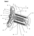
先ず添付図面の図1を参照すると、アウターケーシング1を備える遠心力心臓ポンプが示されており、そのアウターケーシング1はそこに、インペラを有する単一の回転部材(図1には示されず)を有している。アウターケーシング1は、血液の導入口2および血液の遠心方向又は半径方向の排出口3を有しており、導入口2と排出口3との間に血液流路を形作っている。
Referring first to FIG. 1 of the accompanying drawings, there is shown a centrifugal heart pump with an outer casing 1, which has a single rotating member (not shown in FIG. 1) having an impeller therein. Have. The outer casing 1 has a
アウターケーシング1の一部(それは渦形又はポンプ室10を含む)は、心室5の頂部4において心臓の外側に存在し、排出口3は、下行大動脈7に接ぎ木された流出カニューレ(cannula、排管)6に接続されている。流出カニューレ6を上行大動脈8に接ぎ木すること(接ぎ木は示されず)も可能である。心臓の外側にポンプ室を位置決めすることは、ポンプ全体を、それが心臓内に完全に埋め込まれたときに可能である場合よりもずっと大きくすることを可能にする。
A portion of the outer casing 1 (which includes a vortex or pump chamber 10) exists outside the heart at the top 4 of the
流入カニューレ9(図1に外部的に示す)は、ポンプ室間において心室5の壁14を通って心室のチャンバー(室)内に延びており、その結果、導入口2は完全に心室5のチャンバー(室)内にある。
An inflow cannula 9 (shown externally in FIG. 1) extends between the pump chambers through the
ポンプは、裁縫リング12によって心臓に取り付けられることになる。裁縫リング12は、典型的には、縫合糸、組織適合性の接着剤、その二つの組み合わせ、又はその他の適切な取り付け法によって心室5の頂部4の外側に取り付けられる。心室頂部4からの流入カニューレの出現部の周囲に血液止めのシールを形成するために、裁縫リング12と心室頂部4との間にシール性のフェルト(図示略)が閉じ込められてもよい。
The pump will be attached to the heart by a
電気ケーブル17によって電力がポンプに提供される。電気ケーブル17は、外部コンソール及び電力供給源に向けて、又は、トランス・皮膚動力分配装置用のインプラントされた誘導コイルに向けて、経皮的にルートが定められている。
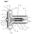
図1における同様の部材は同様の参照番号で表示されているところの図2〜4を参照すると、ケーシングはポンプ室を含み、ポンプ室内には、単一の回転部材21の一体化した部分であるインペラ20がある。図示されたようなインペラ20は、ラジアル流を提供するように構成され(その結果、ポンプはラジアル流タイプ、即ち遠心力ポンプとなっている)。また、インペラは渦巻き部22によって取り囲まれており、渦巻き部22は運動エネルギーを圧力エネルギーに変換して効率を改善することを手助けする。インペラ20は、側板(シュラウド)24によって囲まれた一群のインペラブレード23を備えている。
Referring to FIGS. 2-4, where like elements in FIG. 1 are labeled with like reference numerals, the casing includes a pump chamber, which is an integral part of a single rotating
示されるように、心臓の外側にポンプ室10を位置決めしたことは、インペラ20及び渦巻き部22の両方がポンプ容量及び効率の点で最適化された設計であることを可能ならしめる。
As shown, positioning the
図1〜4の実施形態のポンプに動力供給するモーターは、流入カニューレ9の中に一体的に組み入れられている。モーターのローター28は、インペラ20をも備えると共にポンプ室10から流入カニューレ9の全長を通してポンプ導入口2まで延びる単一の回転部材21と一体化している。コイル30及びラミネーション(積層物)31の静止側(固定側)モーター部品は、流入カニューレ9の壁内に組み込まれている。
A motor for powering the pump of the embodiment of FIGS. 1-4 is integrated into the inflow cannula 9. The
単一の回転部材21は、ポンプの導入口2端部における上流側ベアリング32、及び、ポンプの排出口3端部における下流側ベアリング33によってケーシングに対し回転可能に懸架されている。ここで、下流側ベアリング33は、ボール部材34及びカップ部材35の形態にある(図3参照)。図示されるように、カップ部材35は、プレート部材又はダイアフラム(隔壁)41と一体化したボス部40に設けられている。プレート部材又はダイアフラム(隔壁)は、ボス部よりも薄くて柔軟な材料でできており、そのボス部は前記プレート部材の本体から突出している。
The single rotating
回転部材に最も近接したボス部40の一部(即ち、ボス部の「正面」)は、カップ部材35を含むように形成され、カップ部材35は図示のように、下流側ベアリングを形成すべく、対応するボールベアリング部材34を受け入れる。
The portion of the
ボス部の表面は、外側にねじ切りされた掘りネジ(grubscrew)42と係合するように構成されており、その掘りネジ42は、相補的な内ネジ部47を有する別の内部ねじ切り型の取付けプレート50に設けられており、取付けプレート50そのものは、ポンプ室10に取り付けられている。図示の好ましい実施形態では、取付けプレート50及び掘りネジは共に、回転部材21の軸線に対して対称となっている。
The surface of the boss is configured to engage an externally threaded
図2及び図3は、掘りネジ42がボス部40の表面から最も離れて位置するときの組立時(即ち、この装置が患者にインプラントされる前)の配置構成を示す。ボール部材34がカップ部材35にしっかりと受け止められながらも、ベアリングシートが回転部材21の円滑な回転に最適な位置(これは経験的に決定される)に来るまで、掘りネジがボス部の表面と係合するように、掘りネジ42は、ドライブヘッド(図示略)を用いて矢印Aの方向に(しっかりと)ねじ込まれる。それ故、掘りネジ42が上流側ベアリングと下流側ベアリングの間のセット長の微調整を許容するものであることは、理解されよう。典型的には、取付けプレート50はダイアフラム41よりも硬い(剛性が高い、rigid)ものであり、その結果、後者(ダイアフラム41)だけがボス部40に対する掘りネジ42の締め付けに応答して動く(ことができる)。掘りネジのドライブヘッドは、スロット(細長い隙間)、交差ヘッド、六角形凹部(「アレン・キー」(訳注:六角レンチの類)によって操作可能なもの)等のような公知のタイプのいずれでもよい。
2 and 3 show the arrangement during assembly when the digging
注意すべきは、各ボール34及びカップ35の特徴が、配置又は配向性において逆転され得ること、即ち、ボール34が単一の回転部材21の一部にあることに代えて、ポンプの静止したケーシング1にあることが可能であり、その一方で、カップ35がケーシング1の一部にあることに代えて、ポンプの単一の回転部材21の一部であることが可能である。
It should be noted that the characteristics of each
本発明の例示の実施形態に示されたボール及びカップ型のベアリングに代えて、他のベアリング形式、例えば「V」ベアリングが、本発明に従うポンプにおいて使用可能であることもまた、理解されるべきである。 It should also be understood that instead of the ball and cup type bearings shown in the exemplary embodiment of the present invention, other bearing types such as “V” bearings can be used in the pump according to the present invention. It is.
インペラ側板24内のクリアランス(間隔)は、下流側ベアリング33を洗浄するところの、二つの部位間における血液の二次流路37を可能にする。
The clearance (interval) in the
インペラ側板24、ケーシング1及び下流側ベアリング33の表面は、血液が流れを生じるところのスムーズで連続した面を提供する。その流路は、不都合にも血流のよどみを生じさせ結果的に血栓を生じさせ得る領域のないスムーズで妨害されない流れを提供すべく、最低限の不連続性を持つ(つまり連続性が高い)ものである。
The surfaces of the
図2〜4の実施形態では、セット長が最初はあまりにも長いものであるが、掘りネジが内部に向けて矢印Aの方向に動かされると、セット長は必要量にまで細かくチューニングされる。 In the embodiment of FIGS. 2-4, the set length is initially too long, but if the digging screw is moved in the direction of arrow A towards the inside, the set length is finely tuned to the required amount.
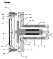
添付図面の図5及び図6を参照すると、これらの図では、多くの部材が図2〜4における部材と対応し、その対応する部材には図2〜4と同じ参照番号が与えられており、それ故、繰り返し詳細な説明はしない。但し、図5及び図6の実施形態では、セット長が最初はあまりにも短いものであるが、ローター21がポンプ内に取り付けられて関連する調節ネジが締め付けられると、ダイアフラム41の屈曲によって広げられる。
Referring to FIGS. 5 and 6 of the accompanying drawings, in these figures, many members correspond to the members in FIGS. 2-4, and the corresponding members are given the same reference numerals as in FIGS. Therefore, detailed description will not be repeated. However, in the embodiment of FIGS. 5 and 6, the set length is initially too short, but when the
図5及び図6の実施形態では、ポンプ室10は、二つの部材、即ち上流側部材10a及び下流側部材10bの中にあり、上流側及び下流側部材は、一方から他方へのスムーズな移行と共に液密なシールを形成すべく一方を他方に連結するよう構成された円周面60a,60bをそれぞれ有している。具体的には、上流側部材10aは、ケーシングの全長の大部分を有し、流入カニューレ9の壁内部に組み込まれるコイル30及びラミネーション(積層物)31を含んでいる。下流側部材10bは、ケーシングの残りの部分を含む、その残りの部分は、ボス部40と一体化したダイアフラム41を含み、前記ボス部は、ボール部材34との相補的な係合のために構成されたカップベアリング部材35を形成する。
In the embodiment of FIGS. 5 and 6, the
図5は、ボール部材34がカップベアリング部材35との相補的な係合のために着座させられる前の、上流側部材10a及び下流側部材10bの組立て前の配置構成を示す。ダイアフラム41は屈曲しておらず、仮にローター21無しでポンプが組み立てられたならば、上流側ベアリング32と下流側ベアリング33との間のセット長は、ローター21上の上流側及び下流側ベアリング間にあるローターの長さよりも短いものとなろう。
FIG. 5 shows the arrangement prior to assembly of the
とりわけ図6を参照すると、上流側部材10aと下流側部材10bとがポンプ内にローター21が含まれた状態で組み立てられたとき、上流側ベアリング32と下流側ベアリング33との間で正しいセット長を達成すべく、ダイアフラム41は屈曲することを強制される。
In particular, referring to FIG. 6, when the
本発明のこの第2の例示的実施形態では、ダイアフラム41は、所望の屈曲(たわみ)がベアリングの作動負荷容量内にあるベアリング間の力(一般には「予荷重」と呼ばれる)で達成されるのをダイアフラムの柔軟性が許容するように設計されている。それ故、この予荷重がポンプの作動期間(作動寿命)の全体を通して維持されるものであることは、理解されよう。
In this second exemplary embodiment of the invention, the
ここで説明した本発明の第2実施形態では、上流側部材10aと下流側部材10bとの間の結合は、確実で恒久的な結合を確保するために、一群のネジ65(それぞれがスロット付きネジ頭65aを有する)を相補的にねじ切りしたメクラ孔64に締め付けることによって達成される。しかしながら、その結合が接着又は溶接のような他の手段よっても達成され得ることは、理解されるべきである。
In the second embodiment of the present invention described here, the connection between the
1 アウターケーシング(ハウジング)
2 導入口(inlet)
3 排出口(outlet)
9 流入カニューレ(inflow cannula、流入排管)
20 インペラ
24 インペラ側板
21 回転部材又はローター(回転可能なポンプ部材)
32 上流側ベアリング
33 下流側ベアリング
34 ボール部材(ベアリング部材)
35 カップベアリング部材(相補的なベアリング構造)
40 ボス部
41 ダイアフラム(プレート部材)
42 ネジ(機械的な調節具)
1 Outer casing (housing)
2 Inlet
3 outlet
9 Inflow cannula (inflow cannula)
20
32 Upstream bearing 33
35 Cup bearing member (complementary bearing structure)
40
42 screws (mechanical adjusters)
Claims (14)
a) 流体の導入口(2)、流体の排出口(3)、及び、前記導入口と前記排出口との間に延びる流路を具備したハウジング(1)と、
b) 前記導入口から前記排出口へ前記流路に沿った流体の流れを生じさせるための、前記ハウジング内のインペラ(20)を含む回転可能なポンプ部材(21)であって、
当該ポンプ部材は、上流側ベアリング(32)及び下流側ベアリング(33)において前記ハウジングに回転可能に結合されており、前記下流側ベアリングは、当該ポンプ部材上のベアリング部材(34)及び前記ハウジング上の相補的なベアリング構造(35)を備えてなる、回転可能なポンプ部材(21)と、
を備えてなる遠心力ポンプにおいて、
当該遠心力ポンプは更に、前記ポンプ部材の軸(A)に沿って前記ベアリング構造(35)の位置を微調整するための機械的な調節具(42)を備えている、ことを特徴とする遠心力ポンプ。 A centrifugal pump,
a) a fluid inlet (2), a fluid outlet (3), and a housing (1) having a flow path extending between the inlet and the outlet;
b) a rotatable pump member (21) including an impeller (20) in the housing for causing a fluid flow along the flow path from the inlet to the outlet;
The pump member is rotatably coupled to the housing at an upstream bearing (32) and a downstream bearing (33), and the downstream bearing is connected to the bearing member (34) on the pump member and the housing. A rotatable pump member (21) comprising a complementary bearing structure (35) of
In a centrifugal pump comprising:
The centrifugal pump further includes a mechanical adjuster (42) for finely adjusting the position of the bearing structure (35) along the axis (A) of the pump member. Centrifugal pump.
ことを特徴とする請求項8又は9に記載の遠心力ポンプ。 The first end is substantially flat and connected to the body of the screw by a frustoconical portion inclined inwardly toward the first end;
The centrifugal pump according to claim 8 or 9, wherein:
ことを特徴とする請求項1〜6のいずれか一項に記載の遠心力ポンプ。 An apparatus for adjustably moving the bearing structure comprises a plurality of helically threaded screws arranged symmetrically around the plate member.
The centrifugal pump according to any one of claims 1 to 6, wherein
前記インペラ(20)は、前記ポンプ部材と前記ハウジングとの間に血液の二次流路を形成するインペラ側板(24)を備え、
前記血液の二次流路は入口および出口を備え、この入口および出口は、前記一次流路と流体連通の状態にあり、前記出口は前記入口に対して前記一次流路の上流側にあり、その結果、前記一次流路に沿った血液流は、前記入口での圧力に対して前記出口での圧力の低下をもたらし、前記二次流路に沿った血液の流れをもたらす、
ことを特徴とする心臓ポンプ。 The pump according to any one of claims 1 to 11, wherein the flow path is a heart pump serving as a primary flow path of blood,
The impeller (20) includes an impeller side plate (24) that forms a secondary blood flow path between the pump member and the housing,
The blood secondary channel comprises an inlet and an outlet, the inlet and outlet being in fluid communication with the primary channel, the outlet being upstream of the primary channel relative to the inlet; As a result, blood flow along the primary flow path results in a drop in pressure at the outlet relative to the pressure at the inlet, resulting in blood flow along the secondary flow path.
A heart pump characterized by that.
前記導入口は前記カニューレ部に配置され、前記排出口は前記ポンプ室に配置されている、ことを特徴とする請求項12に記載の心臓ポンプ。 The housing includes a cannula part (9) and a pump part including a pump chamber,
The heart pump according to claim 12, wherein the introduction port is disposed in the cannula portion, and the discharge port is disposed in the pump chamber.
Applications Claiming Priority (3)
| Application Number | Priority Date | Filing Date | Title |
|---|---|---|---|
| GB1218768.8 | 2012-10-18 | ||
| GBGB1218768.8A GB201218768D0 (en) | 2012-10-18 | 2012-10-18 | Centrifugal pumps |
| PCT/GB2013/052718 WO2014060765A1 (en) | 2012-10-18 | 2013-10-17 | Centrifugal pump |
Publications (2)
| Publication Number | Publication Date |
|---|---|
| JP2016500534A true JP2016500534A (en) | 2016-01-14 |
| JP2016500534A5 JP2016500534A5 (en) | 2016-12-01 |
Family
ID=47359118
Family Applications (1)
| Application Number | Title | Priority Date | Filing Date |
|---|---|---|---|
| JP2015537352A Ceased JP2016500534A (en) | 2012-10-18 | 2013-10-17 | Centrifugal pump |
Country Status (8)
| Country | Link |
|---|---|
| US (1) | US20150285258A1 (en) |
| EP (1) | EP2908879A1 (en) |
| JP (1) | JP2016500534A (en) |
| CN (1) | CN104902939A (en) |
| BR (1) | BR112015008784A2 (en) |
| GB (1) | GB201218768D0 (en) |
| IN (1) | IN2015DN04020A (en) |
| WO (1) | WO2014060765A1 (en) |
Families Citing this family (23)
| Publication number | Priority date | Publication date | Assignee | Title |
|---|---|---|---|---|
| EP3325036B1 (en) | 2015-07-21 | 2021-02-24 | Tc1 Llc | Cantilevered rotor pump for axial flow blood pumping |
| WO2017205909A1 (en) * | 2016-06-01 | 2017-12-07 | Peter Ayre | Ventricle assist device |
| US10857273B2 (en) | 2016-07-21 | 2020-12-08 | Tc1 Llc | Rotary seal for cantilevered rotor pump and methods for axial flow blood pumping |
| WO2018031741A1 (en) | 2016-08-12 | 2018-02-15 | Tc1 Llc | Devices and methods for monitoring bearing and seal performance |
| CN107115573A (en) * | 2017-05-09 | 2017-09-01 | 李国荣 | Single fulcrum centrifugal pump heart-assist device |
| EP3634528B1 (en) | 2017-06-07 | 2023-06-07 | Shifamed Holdings, LLC | Intravascular fluid movement devices, systems, and methods of use |
| US11672968B2 (en) * | 2017-08-11 | 2023-06-13 | Carnegie Mellon University | Blood-immersed bearing system for a blood pump |
| CN111556763B (en) | 2017-11-13 | 2023-09-01 | 施菲姆德控股有限责任公司 | Intravascular fluid movement device and system |
| EP4085965A1 (en) | 2018-02-01 | 2022-11-09 | Shifamed Holdings, LLC | Intravascular blood pumps and methods of use and manufacture |
| EP3574932A1 (en) * | 2018-05-28 | 2019-12-04 | Berlin Heart GmbH | Blood pump |
| EP3574933A1 (en) * | 2018-05-29 | 2019-12-04 | Berlin Heart GmbH | Blood pump with a drivable rotor and two bearings |
| GB2583512B (en) * | 2019-05-02 | 2023-05-24 | Calon Cardio Tech Ltd | A cardiac pump |
| US11964145B2 (en) | 2019-07-12 | 2024-04-23 | Shifamed Holdings, Llc | Intravascular blood pumps and methods of manufacture and use |
| US11654275B2 (en) | 2019-07-22 | 2023-05-23 | Shifamed Holdings, Llc | Intravascular blood pumps with struts and methods of use and manufacture |
| US11724089B2 (en) | 2019-09-25 | 2023-08-15 | Shifamed Holdings, Llc | Intravascular blood pump systems and methods of use and control thereof |
| EP4058093A1 (en) | 2019-11-12 | 2022-09-21 | Fresenius Medical Care Deutschland GmbH | Blood treatment systems |
| CN114728159A (en) | 2019-11-12 | 2022-07-08 | 费森尤斯医疗护理德国有限责任公司 | Blood treatment system |
| WO2021094144A1 (en) | 2019-11-12 | 2021-05-20 | Fresenius Medical Care Deutschland Gmbh | Blood treatment systems |
| EP4058094A1 (en) | 2019-11-12 | 2022-09-21 | Fresenius Medical Care Deutschland GmbH | Blood treatment systems |
| IL293625A (en) | 2019-12-03 | 2022-08-01 | Procyrion Inc | Blood pumps |
| AU2020403115A1 (en) | 2019-12-13 | 2022-07-14 | Procyrion, Inc. | Support structures for intravascular blood pumps |
| EP4093480A1 (en) * | 2020-01-21 | 2022-11-30 | Boston Scientific Scimed Inc. | Electromagnetically driven blood pump |
| US11648393B2 (en) * | 2020-03-17 | 2023-05-16 | Heartware, Inc. | Implantable blood pump with thrombus diverter |
Citations (2)
| Publication number | Priority date | Publication date | Assignee | Title |
|---|---|---|---|---|
| JPH0681835A (en) * | 1990-10-31 | 1994-03-22 | Soc Europ Propulsion <Sep> | Rotary machine with automatic retreating axial abutting mechanism by flexible film receiving action of fluid pressure |
| JPH11123239A (en) * | 1997-08-13 | 1999-05-11 | Kriton Medical Inc | Non-seal blood pump |
Family Cites Families (12)
| Publication number | Priority date | Publication date | Assignee | Title |
|---|---|---|---|---|
| FR2451480A1 (en) * | 1979-03-16 | 1980-10-10 | Belenger Jacques | MEDICAL CENTRIFUGAL PUMP |
| US5112202A (en) * | 1990-01-31 | 1992-05-12 | Ntn Corporation | Turbo pump with magnetically supported impeller |
| US5695471A (en) * | 1996-02-20 | 1997-12-09 | Kriton Medical, Inc. | Sealless rotary blood pump with passive magnetic radial bearings and blood immersed axial bearings |
| US6293901B1 (en) * | 1997-11-26 | 2001-09-25 | Vascor, Inc. | Magnetically suspended fluid pump and control system |
| US6227820B1 (en) * | 1999-10-05 | 2001-05-08 | Robert Jarvik | Axial force null position magnetic bearing and rotary blood pumps which use them |
| JP3996775B2 (en) * | 2002-01-09 | 2007-10-24 | テルモ株式会社 | Centrifugal liquid pump device |
| US20070299297A1 (en) * | 2006-06-26 | 2007-12-27 | Robert Jarvik | Textured conforming shell for stabilization of the interface of precision heart assist device components to tissues |
| JP5171953B2 (en) * | 2008-06-23 | 2013-03-27 | テルモ株式会社 | Blood pump device |
| CN102341600B (en) * | 2009-03-06 | 2014-12-10 | 胸腔科技有限公司 | Centrifugal pump device |
| US20110118537A1 (en) * | 2009-11-04 | 2011-05-19 | Richard Wampler | Methods and devices for treating heart failure |
| EP2627366B1 (en) * | 2010-10-13 | 2016-08-31 | Thoratec Corporation | Blood pump |
| JP5673795B2 (en) * | 2011-02-24 | 2015-02-18 | 株式会社ジェイ・エム・エス | Turbo blood pump and method for manufacturing the same |
-
2012
- 2012-10-18 GB GBGB1218768.8A patent/GB201218768D0/en not_active Ceased
-
2013
- 2013-10-17 US US14/436,196 patent/US20150285258A1/en not_active Abandoned
- 2013-10-17 BR BR112015008784A patent/BR112015008784A2/en not_active IP Right Cessation
- 2013-10-17 CN CN201380053889.3A patent/CN104902939A/en active Pending
- 2013-10-17 WO PCT/GB2013/052718 patent/WO2014060765A1/en active Application Filing
- 2013-10-17 JP JP2015537352A patent/JP2016500534A/en not_active Ceased
- 2013-10-17 EP EP13783628.4A patent/EP2908879A1/en not_active Withdrawn
-
2015
- 2015-05-12 IN IN4020DEN2015 patent/IN2015DN04020A/en unknown
Patent Citations (2)
| Publication number | Priority date | Publication date | Assignee | Title |
|---|---|---|---|---|
| JPH0681835A (en) * | 1990-10-31 | 1994-03-22 | Soc Europ Propulsion <Sep> | Rotary machine with automatic retreating axial abutting mechanism by flexible film receiving action of fluid pressure |
| JPH11123239A (en) * | 1997-08-13 | 1999-05-11 | Kriton Medical Inc | Non-seal blood pump |
Also Published As
| Publication number | Publication date |
|---|---|
| CN104902939A (en) | 2015-09-09 |
| BR112015008784A2 (en) | 2017-07-04 |
| GB201218768D0 (en) | 2012-12-05 |
| IN2015DN04020A (en) | 2015-10-02 |
| EP2908879A1 (en) | 2015-08-26 |
| WO2014060765A1 (en) | 2014-04-24 |
| US20150285258A1 (en) | 2015-10-08 |
Similar Documents
| Publication | Publication Date | Title |
|---|---|---|
| JP2016500534A (en) | Centrifugal pump | |
| US9162018B2 (en) | Cardiac pump | |
| US10251986B2 (en) | Intravascular ventricular assist device | |
| CN101969886B (en) | Ventricular assist device for intraventricular placement | |
| US10195324B2 (en) | Bearing for a cardiac pump | |
| CN102176933B (en) | Cardiac assist devices | |
| US5503615A (en) | Implantable cardiac ventricular assist device and controller thereof | |
| US20050250975A1 (en) | Blood pump with dual inlet passages | |
| US20050107657A1 (en) | Dual inlet mixed-flow blood pump | |
| JP2017517333A (en) | Heart pump | |
| EP0986409A1 (en) | Ventricular assist device comprising an enclosed-impeller axial flow blood pump | |
| CN108472422A (en) | Implantable Mechanical circulatory support equipment | |
| JP2021532958A (en) | Open electric pump | |
| CA2517236A1 (en) | Blood pump with frusto-conical bearing structure |
Legal Events
| Date | Code | Title | Description |
|---|---|---|---|
| A521 | Request for written amendment filed |
Free format text: JAPANESE INTERMEDIATE CODE: A523 Effective date: 20161013 |
|
| A621 | Written request for application examination |
Free format text: JAPANESE INTERMEDIATE CODE: A621 Effective date: 20161013 |
|
| A01 | Written decision to grant a patent or to grant a registration (utility model) |
Free format text: JAPANESE INTERMEDIATE CODE: A01 Effective date: 20170725 |
|
| A045 | Written measure of dismissal of application [lapsed due to lack of payment] |
Free format text: JAPANESE INTERMEDIATE CODE: A045 Effective date: 20171128 |