JP2016218963A - Information processing apparatus, input control program, and input control method - Google Patents
Information processing apparatus, input control program, and input control method Download PDFInfo
- Publication number
- JP2016218963A JP2016218963A JP2015106458A JP2015106458A JP2016218963A JP 2016218963 A JP2016218963 A JP 2016218963A JP 2015106458 A JP2015106458 A JP 2015106458A JP 2015106458 A JP2015106458 A JP 2015106458A JP 2016218963 A JP2016218963 A JP 2016218963A
- Authority
- JP
- Japan
- Prior art keywords
- input
- area
- information processing
- processing apparatus
- character
- Prior art date
- Legal status (The legal status is an assumption and is not a legal conclusion. Google has not performed a legal analysis and makes no representation as to the accuracy of the status listed.)
- Pending
Links
Images


Classifications
-
- G—PHYSICS
- G06—COMPUTING; CALCULATING OR COUNTING
- G06F—ELECTRIC DIGITAL DATA PROCESSING
- G06F3/00—Input arrangements for transferring data to be processed into a form capable of being handled by the computer; Output arrangements for transferring data from processing unit to output unit, e.g. interface arrangements
- G06F3/01—Input arrangements or combined input and output arrangements for interaction between user and computer
- G06F3/048—Interaction techniques based on graphical user interfaces [GUI]
- G06F3/0487—Interaction techniques based on graphical user interfaces [GUI] using specific features provided by the input device, e.g. functions controlled by the rotation of a mouse with dual sensing arrangements, or of the nature of the input device, e.g. tap gestures based on pressure sensed by a digitiser
- G06F3/0488—Interaction techniques based on graphical user interfaces [GUI] using specific features provided by the input device, e.g. functions controlled by the rotation of a mouse with dual sensing arrangements, or of the nature of the input device, e.g. tap gestures based on pressure sensed by a digitiser using a touch-screen or digitiser, e.g. input of commands through traced gestures
- G06F3/04883—Interaction techniques based on graphical user interfaces [GUI] using specific features provided by the input device, e.g. functions controlled by the rotation of a mouse with dual sensing arrangements, or of the nature of the input device, e.g. tap gestures based on pressure sensed by a digitiser using a touch-screen or digitiser, e.g. input of commands through traced gestures for inputting data by handwriting, e.g. gesture or text
-
- G—PHYSICS
- G06—COMPUTING; CALCULATING OR COUNTING
- G06F—ELECTRIC DIGITAL DATA PROCESSING
- G06F3/00—Input arrangements for transferring data to be processed into a form capable of being handled by the computer; Output arrangements for transferring data from processing unit to output unit, e.g. interface arrangements
- G06F3/01—Input arrangements or combined input and output arrangements for interaction between user and computer
- G06F3/018—Input/output arrangements for oriental characters
-
- G—PHYSICS
- G06—COMPUTING; CALCULATING OR COUNTING
- G06F—ELECTRIC DIGITAL DATA PROCESSING
- G06F3/00—Input arrangements for transferring data to be processed into a form capable of being handled by the computer; Output arrangements for transferring data from processing unit to output unit, e.g. interface arrangements
- G06F3/01—Input arrangements or combined input and output arrangements for interaction between user and computer
- G06F3/02—Input arrangements using manually operated switches, e.g. using keyboards or dials
- G06F3/023—Arrangements for converting discrete items of information into a coded form, e.g. arrangements for interpreting keyboard generated codes as alphanumeric codes, operand codes or instruction codes
- G06F3/0233—Character input methods
- G06F3/0236—Character input methods using selection techniques to select from displayed items
-
- G—PHYSICS
- G06—COMPUTING; CALCULATING OR COUNTING
- G06F—ELECTRIC DIGITAL DATA PROCESSING
- G06F3/00—Input arrangements for transferring data to be processed into a form capable of being handled by the computer; Output arrangements for transferring data from processing unit to output unit, e.g. interface arrangements
- G06F3/01—Input arrangements or combined input and output arrangements for interaction between user and computer
- G06F3/048—Interaction techniques based on graphical user interfaces [GUI]
- G06F3/0484—Interaction techniques based on graphical user interfaces [GUI] for the control of specific functions or operations, e.g. selecting or manipulating an object, an image or a displayed text element, setting a parameter value or selecting a range
- G06F3/04842—Selection of displayed objects or displayed text elements
Abstract
Description
本発明は、情報処理装置、入力制御プログラム及び入力制御方法に関する。 The present invention relates to an information processing apparatus, an input control program, and an input control method.
近年、タッチパネル等の入力デバイスを備える情報処理装置が普及してきている。タッチパネルは、例えば、LCD(Liquid Crystal Display)等の表示デバイスに、ユーザ操作による接触位置の座標を検出するデバイスを重畳させて組合せた入力デバイスである。タッチパネルを備える情報処理装置として、例えば、PC(Personal Computer)、携帯
電話機、スマートフォン、ノートPC、タブレットPC、PDA(Personal Data Assistance)、ゲーム機、ナビゲーション装置等が例示できる。
In recent years, information processing apparatuses including an input device such as a touch panel have become widespread. The touch panel is an input device in which a device for detecting coordinates of a contact position by a user operation is superimposed on a display device such as an LCD (Liquid Crystal Display). Examples of the information processing apparatus including a touch panel include a PC (Personal Computer), a mobile phone, a smartphone, a notebook PC, a tablet PC, a PDA (Personal Data Assistance), a game machine, and a navigation device.
上記の情報処理装置では、例えば、表示デバイスに文字入力等に係るオブジェクトが表示される。情報処理装置の操作者(以下、ユーザとも称す)は、例えば、文字入力等に係るオブジェクトの表示領域に操作指等を接触させてタッチ操作を行うことで所定の文字入力を行うことができる。タッチ操作による文字入力のインターフェースとして、以下の入力形態が知られている。 In the information processing apparatus, for example, an object related to character input or the like is displayed on the display device. An operator of the information processing apparatus (hereinafter also referred to as a user) can perform predetermined character input by performing a touch operation by bringing an operation finger or the like into contact with an object display area related to character input, for example. The following input forms are known as an interface for character input by a touch operation.
例えば、表示デバイスには、仮名文字の入力操作について、50音表の“あかさたなはまやらわ”といった各行の「あ」の段がテンキーのように配置されたオブジェクトが表示されるとする。情報処理装置は、例えば、各オブジェクトの表示領域におけるタッチ操作の繰り返しを検出し(トグル入力)、表示されたオブジェクトの切り替えを行う。例えば、情報処理装置は、タッチ操作の繰り返しに応じて、表示された各行の仮名文字を、「あ」段→「い」段→「う」段→「え」段→「お」段のように切り替える。ユーザは、トグル入力で表示された表示文字を切り替えることで所望の文字入力を行うことができる。 For example, it is assumed that the display device displays an object in which “A” in each row such as “Akasana Hamaharawa” in the 50-sound table is arranged like a numeric keypad for an input operation of kana characters. For example, the information processing apparatus detects repetition of a touch operation in the display area of each object (toggle input), and switches the displayed object. For example, in response to repeated touch operations, the information processing apparatus changes the displayed kana characters of each line as “a” row → “i” row → “u” row → “e” row → “o” row. Switch to. The user can input a desired character by switching display characters displayed by toggle input.
また、表示デバイスには、例えば、“あかさたなはまやらわ”といった各行の「あ」の段がテンキーのように配置された周囲に、十字型や扇形に他の4段(い段、う段、え段、お段)を配置することができる。情報処理装置は、例えば、各行の「あ」段のキーが表示された領域から、目的の文字が配置された領域方向に指の接触位置を弾くように移動させるフリック操作を検出する。情報処理装置では、フリック操作の移動方向に対応する領域に配置された文字が入力文字として選択される。ユーザは、各行の表示領域から、目的の文字が配置された領域方向のフリック操作により、所望の文字入力を行うことができる。 In addition, the display device includes, for example, “Akasana Hamawara” where the “A” column in each row is arranged like a numeric keypad, and the other four columns in the shape of a cross or a fan. , Edan, dan) can be arranged. For example, the information processing device detects a flick operation for moving the finger contact position in the direction of the area where the target character is arranged from the area where the “A” key of each row is displayed. In the information processing apparatus, a character arranged in an area corresponding to the moving direction of the flick operation is selected as an input character. The user can input a desired character from the display area of each line by a flick operation in the direction of the area where the target character is arranged.
なお、本明細書で説明する技術に関連する技術が記載されている先行技術文献としては、以下の特許文献が存在している。 In addition, the following patent documents exist as prior art documents in which technologies related to the technologies described in this specification are described.
上述のトグル式、フリック式による入力形態では、タッチパネル面に表示された“あかさたなはまやらわ”といった、最初の操作対象となる文字行の表示領域が接触される。こ
のため、例えば、表示デバイスが小型の場合、タッチパネルの表示領域が狭い場合には、隣接する操作オブジェクトへの誤接触による押し間違えが発生しやすいという問題があった。誤接触による押し間違え等を抑制するために、ペン型の接触器の使用や表示オブジェクトの数量を減らして多段階のメニュー選択を行う等の入力形態が考えられる。しかし、ペン型等の接触器の使用や多段階のメニュー選択を行う等の入力インターフェースでは、トグル式、フリック式の入力インターフェースに比べ煩わしいといった操作性の問題がある。
In the input type by the toggle type and the flick type described above, the display area of the character line that is the first operation target such as “Akasana Hamawara” displayed on the touch panel surface is touched. For this reason, for example, when the display device is small and the display area of the touch panel is narrow, there has been a problem that a push error due to erroneous contact with an adjacent operation object is likely to occur. In order to suppress erroneous pressing due to erroneous contact, an input form such as the use of a pen-type contactor or the selection of multi-level menus by reducing the number of display objects is conceivable. However, an input interface such as using a pen-type contactor or performing multi-level menu selection has a problem of operability that is more cumbersome than a toggle type or flick type input interface.
1つの側面では、本発明は、狭小なタッチパネルを用いた情報入力の操作性を向上可能な技術の提供を目的とする。 In one aspect, an object of the present invention is to provide a technique capable of improving the operability of information input using a narrow touch panel.
上記技術は、次の情報処理装置の構成によって例示できる。すなわち、情報処理装置は、操作面に対する接触位置が操作面の周辺領域から中心領域に移動する第1段目の操作の方向と、第1段目の操作に継続した接触位置の中心領域から周辺領域に移動する第2段目の操作の方向とを検出する検出部と、第1段目の操作の方向に基づいて、入力の項目群の中から対象項目を特定し、特定した対象項目の中から第2段目の操作の方向に対応する入力候補を特定する処理部と、を備える。 The above technique can be exemplified by the following configuration of the information processing apparatus. That is, the information processing apparatus detects the direction of the first stage operation in which the contact position with respect to the operation surface moves from the peripheral area of the operation surface to the central area, and the peripheral area from the central area of the contact position continued to the first stage operation. Based on the detection unit that detects the direction of the second-stage operation that moves to the area, and the direction of the first-stage operation, the target item is identified from the input item group, and the identified target item A processing unit that identifies input candidates corresponding to the direction of the second-stage operation from the inside.
上記の情報処理装置によれば、本発明は、狭小なタッチパネルを用いた情報入力の操作性を向上可能な技術が提供できる。 According to the information processing apparatus, the present invention can provide a technique capable of improving the operability of information input using a narrow touch panel.
以下、図面を参照して、一実施形態に係る情報処理装置について説明する。以下の実施
形態の構成は例示であり、情報処理装置は実施形態の構成には限定されない。
Hereinafter, an information processing apparatus according to an embodiment will be described with reference to the drawings. The configuration of the following embodiment is an exemplification, and the information processing apparatus is not limited to the configuration of the embodiment.
以下、図1から図7の図面に基づいて、情報処理装置を説明する。 Hereinafter, the information processing apparatus will be described with reference to FIGS. 1 to 7.
<実施形態>
図1に、本実施形態の情報処理装置のハードウェアの構成を例示する。本実施形態の情報処理装置10は、例えば、タッチパネルやタッチパッド等の操作者(以下、ユーザとも称す)の操作によるデバイスへの接触位置の座標を検出する入力デバイスを備える。タッチパネルは、例えば、LCD(Liquid Crystal Display)等の表示デバイスに、ユーザの操作による接触位置の座標を検出するデバイスを重畳させて組合せた入力デバイスである。また、タッチパッドは表示デバイスと重畳させずに分離した状態でユーザの操作による接触位置の座標を検出する入力デバイスである。
<Embodiment>
FIG. 1 illustrates the hardware configuration of the information processing apparatus according to the present embodiment. The
情報処理装置10には、例えば、PC(PC:Personal Computer)、携帯電話機、ス
マートフォン、ノートPC、タブレットPC、PDA(Personal Data Assistance)、ゲーム機、ナビゲーション装置等の情報処理装置が含まれる。なお、情報処理装置10は、ユーザの操作による接触位置の座標を検出する入力デバイスを備える電子機器であれば、例えば、腕時計やリストバンド等のユーザに装着可能なウェアラブル式の電子機器であってもよい。
The
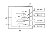
図1に例示の情報処理装置10は、出力部15にLCD15a等の表示デバイスを備える。また、情報処理装置10は、入力部14にタッチセンサ14a等の、デバイス面に対する接触位置の座標を検出するデバイスを備える。ここで、「デバイス面」が操作面の一例である。タッチセンサ14aは、例えば、LCD15a等の表示デバイスと組合せたタッチパネルでも、分離した状態のままタッチパッドでもよく、ポインティングデバイスとして機能する。以降の説明は例としてLCD15aの表示デバイスと組み合わせたタッチパネルとして説明する。
The
タッチセンサ14aは、例えば、静電容量、電圧、圧力、光、振動等の物理量の変化を検出信号として捉え、デバイス面に対する操作指等の接触を検知する。また、タッチセンサ14aは、上述した物理量の接触状態を示す検出信号の変化から、接触された操作指等の離脱を検知する。タッチセンサ14aにより検知されたデバイス面上の接触および離脱は、例えば、デバイス面上の検出信号が変化した位置を示す座標として検出される。
The
タッチセンサ14aで検出される座標は、例えば、デバイスの左上角部を原点とし、表示デバイスの左右方向をX軸、上下方向をY軸とした(X,Y)の2次元座標として表すことができる。
The coordinates detected by the
以下の説明において、タッチパネルのデバイス面を“タッチパネル領域”、操作指等の接触を検出する領域を“入力領域”とも称する。 In the following description, the device surface of the touch panel is also referred to as a “touch panel region”, and a region for detecting contact with an operation finger or the like is also referred to as an “input region”.
情報処理装置10は、入力領域で発生した、操作指等によるタッチ操作の接触位置を検出する。また、情報処理装置10は、接触させた操作指等の入力領域からの離脱位置を検出する。また、情報処理装置10は、入力領域内で接触状態にある操作指等の、接触位置を示す座標の位置変化から移動を検出する。接触状態にある操作指等の入力領域内の移動は、例えば、10ms、16.6ms、20ms等の一定周期でサンプリングされた接触位置の位置変化から検出される。サンプリングされた接触位置の履歴は時系列データとなる。サンプリングされた接触位置を示す座標の時系列データは、例えば、デバイス上の軌跡として表すことができる。
The
情報処理装置10は、例えば、接触状態にある操作指等の軌跡から、入力領域内の移動方向を検出する。移動方向は、例えば、サンプリングされた時系列データの接触位置間を結ぶ軌跡とX軸との間の相対角度で表すことができる。例えば、移動方向は、X軸の正方向を“0°”として左回転方向に相対角度を定義することができる。ここで、サンプリングされた時系列データのうち前後する接触位置を、それぞれP1(X1,Y1)、P2(X2,Y2)で表すとする。座標P1と座標P2の間を結ぶ軌跡とY軸との相対角度(θ)は、例えば、逆三角関数“atan”を用いて、(θ)=atan((Y2−Y1)/(X2−X1))として求めることができる。
For example, the
なお、情報処理装置10は、接触状態にある操作指等の移動に伴う軌跡からは、入力領域内の移動量を求めることができる。また、接触状態にある操作指等の移動に伴う移動量の時間変化からは移動速度を求めることができる。情報処理装置10は、単位時間当たりの移動量から移動速度を求めることができる。
Note that the
情報処理装置10は、例えば、入力領域で検出した接触位置の座標が所定範囲内に収まり、接触後に離脱した場合には、接触位置に対するタッチ操作(タップ操作とも称す)を検出できる。
The
また、情報処理装置10は、例えば、操作指等が接触状態で入力領域内を移動し、移動速度を速めて離脱した場合には、接触させた操作指等を弾くように移動させるタッチ操作(フリック操作とも称す)を検出できる。また、操作指等が接触状態でタッチパネル領域内を移動し、移動速度を落して停止する(移動後の接触位置に一定時間留まる)タッチ操作、或いは、移動後に離脱するタッチ操作(スワイプ操作、スライド操作とも称す)を検出できる。以降、本説明ではフリック操作とスワイプ操作とスライド操作を総じてフリック操作と称する。情報処理装置10は、フリック操作を検出することで、フリック操作に伴う移動方向、移動量、移動により経過した領域(軌跡を含む領域)等を特定できる。
Further, for example, when the operation finger or the like moves in the input area in a contact state and is released at a high moving speed, the
(タッチパネル領域)
本実施形態の情報処理装置10は、デバイス面であるタッチパネル領域内の操作指等の接触を検出する入力領域内に、タッチ操作の種類を判別するための判別領域を設ける。判別領域により、タッチパネル領域は、判別領域内と判別領域外とに区分けされる。本実施形態の情報処理装置10は、判別領域内と判別領域外とに区分けされた各領域内の座標に基づいて、タッチ操作の種類を判別する。
(Touch panel area)
The
本実施形態の情報処理装置10は、例えば、判別領域内から判別領域外への移動を伴うフリック操作、判別領域外から判別領域内への移動を伴うフリック操作を判別する。また、例えば、情報処理装置10は、判別領域内のタップ操作を判別する。判別されたタッチ操作がフリック操作の場合には、情報処理装置10は、移動軌跡からフリック操作の移動方向、移動量、移動により経過した領域等を特定することができる。本実施形態の情報処理装置10は、例えば、判別されたタッチ操作の種類と移動方向とを組み合わせた、組合せパターンに基づいて、該タッチ操作に関連付けされた情報の入力項目を識別する。
The
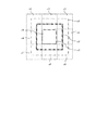
図2Aに、本実施形態の情報処理装置10のタッチパネル領域の説明図を例示する。図2Aに例示の矩形状のタッチパネル領域a1は、例えば、LCD15a等の表示デバイスの表示領域に重ね合わせてもよい。また、タッチパネル領域a1、入力領域a2、及び判別領域a3は矩形状の領域に限定されるわけではない。タッチパネルを備える電子機器の形状や使用目的、タッチパネルのサイズ等に応じて、タッチパネル領域a1、入力領域a2及び判別領域a3が設定される。タッチパネル領域a1、入力領域a2及び判別領域a3の形状は、例えば、楕円形状、6角形や星形等の多角形状等であってもよい。入力領域a2及び判別領域a3内に発生した操作指等の接触位置を検出し、タッチ操作の種類、移
動方向を判別できる形状であればよい。
FIG. 2A illustrates an explanatory diagram of the touch panel area of the
図2Aに例示のように、タッチパネル領域a1には、入力領域a2及び判別領域a3が含まれる。タッチパネル領域a1内の入力領域a2、判別領域a3は、タッチ操作の対象となる情報についての操作入力が行われる領域である。入力領域a2の座標は、入力領域a2内に存在する判別領域a3により、判別領域a3内の座標と判別領域a3外の座標とに区分けされる。情報処理装置10は、判別領域a3内の座標と判別領域a3外の座標とに基づいて、例えば、入力領域a2内で発生したタッチ操作の種類と移動方向との組合せパターンで関連付けされる情報の入力項目を識別する。
As illustrated in FIG. 2A, the touch panel area a1 includes an input area a2 and a determination area a3. The input area a2 and the determination area a3 in the touch panel area a1 are areas in which operation input is performed on information to be touched. The coordinates of the input area a2 are divided into the coordinates in the determination area a3 and the coordinates outside the determination area a3 by the determination area a3 existing in the input area a2. Based on the coordinates in the determination area a3 and the coordinates outside the determination area a3, the
なお、図2Aに例示の入力領域a2は、タッチパネル領域a1と互いの中心位置を共通とした同心状の矩形状の領域例である。但し、タッチパネル領域a1内の入力領域a2は、一定方向に偏るようにしてもよい。入力領域a2内に判別領域a3が含まれていればよい。例えば、タッチパネル領域a1は、文字入力に係る領域と、入力した文字等が表示される領域に2分割されているとする。2分割されたタッチパネル領域a1内の、文字入力に係る領域が、一定方向に偏って設けられた入力領域a2として例示できる。また、重ね合わせた表示デバイスの表示領域の文字入力に係る領域に入力の方向や入力領域の境目を目視できるように表示したり、状態に合わせた入力文字候補などを表示してもよい。 Note that the input area a2 illustrated in FIG. 2A is an example of a concentric rectangular area having a common center position with the touch panel area a1. However, the input area a2 in the touch panel area a1 may be biased in a certain direction. It is only necessary that the determination area a3 is included in the input area a2. For example, it is assumed that the touch panel area a1 is divided into two parts: an area related to character input and an area where input characters and the like are displayed. The area | region which concerns on the character input in the touch panel area | region a1 divided into 2 can be illustrated as the input area a2 provided by being biased in the fixed direction. In addition, the input direction and the boundary of the input area may be displayed so that the input direction and the boundary of the input area can be seen in the area related to the character input in the display area of the superimposed display device, or input character candidates matched to the state may be displayed.
判別領域a3は、入力領域a2内で発生した、判別領域a3内から判別領域a3外へ移動するタッチ操作を判別する領域である。同様にして、判別領域a3は、判別領域a3外から判別領域a3内へ移動するタッチ操作を判別する領域である。また、判別領域a3は、判別領域a3内で接触させた操作指等が移動せずに離脱するタッチ操作を判別する領域である。 The determination area a3 is an area for determining a touch operation that occurs in the input area a2 and moves from the determination area a3 to the outside of the determination area a3. Similarly, the determination area a3 is an area for determining a touch operation that moves from outside the determination area a3 into the determination area a3. The discrimination area a3 is an area for discriminating a touch operation in which the operating finger or the like touched in the discrimination area a3 is released without moving.
さらに、情報処理装置10は、判別領域a3内を移動するタッチ操作、或いは、判別領域a3外の入力領域a2を移動するタッチ操作を判別することができる。情報処理装置10は、例えば、判別領域a3を用いて判別されたタッチ操作が移動を伴う場合には、移動に伴う移動方向等を特定する。
Furthermore, the
判別領域a3の領域サイズは、判別領域a3内に発生した操作指等の接触位置を検出し、タッチ操作の種類、移動方向を判別可能な領域サイズであればよい。 The area size of the determination area a3 may be any area size that can detect the contact position of an operation finger or the like generated in the determination area a3 and determine the type of touch operation and the moving direction.
なお、入力領域a2に対する判別領域a3の相対的な位置は、判別領域a3内から判別領域a3外へ向かうフリック操作および移動方向、判別領域a3外から判別領域a3内へ向かうフリック操作および移動方向を判別可能な位置であればよい。判別領域a3の領域サイズや入力領域a2に対する判別領域a3の相対的な設定位置については、例えば、以下の設定手順で処理することができる。 The relative position of the determination area a3 with respect to the input area a2 is determined by the flick operation and movement direction from the determination area a3 to the outside of the determination area a3, and the flick operation and movement direction from the outside of the determination area a3 to the determination area a3. Any position that can be discriminated is acceptable. The area size of the determination area a3 and the relative setting position of the determination area a3 with respect to the input area a2 can be processed, for example, by the following setting procedure.
先ず、タッチパネル領域a1内の入力領域a2に判別領域a3を仮決めする。次に、仮決めされた入力領域a2と判別領域a3の各領域に対する各フリック操作を試行し、各操作の検出率などに基づいて、入力領域a2内の判別領域a3の位置や領域サイズを決定することができる。また、このような設定手順で処理された判別領域a3を用いて入力操作を行い、ユーザの使い易さに応じて判別領域a3の領域サイズを決定することでもよい。情報処理装置10は、判別領域a3を用いたタッチ操作のユーザビリティを向上できる。
First, the determination area a3 is provisionally determined as the input area a2 in the touch panel area a1. Next, each flick operation on each of the temporarily determined input area a2 and determination area a3 is tried, and the position and area size of the determination area a3 in the input area a2 are determined based on the detection rate of each operation. can do. Alternatively, an input operation may be performed using the determination area a3 processed in such a setting procedure, and the area size of the determination area a3 may be determined according to the user's ease of use. The
図2Aに例示の判別領域a3は、入力領域a2と互いの中心位置を共通とする同心状に判別領域a3を設定した一例である。 The discrimination area a3 illustrated in FIG. 2A is an example in which the discrimination area a3 is set concentrically with the input center a2 having a common center position.
タッチ操作を行うユーザは、入力領域a2の範囲を目視により確認することで、入力領
域a2の中心位置を推定できる為、判別領域a3を入力領域a2の中心位置を含む中央部分の領域に設けることが望ましい。中心位置が推定された結果、タッチ操作を行うユーザについては、入力領域a2の外縁から中心位置に向かう、或いは、中心位置から入力領域a2の外縁に向かうフリック操作を行い易くなる効果が期待できる。また、タッチ操作を行うユーザについて、入力領域a2の中心位置に対するタップ操作を行い易くなる効果が期待できる。
The user who performs the touch operation can estimate the center position of the input area a2 by visually confirming the range of the input area a2. Therefore, the determination area a3 is provided in the central area including the center position of the input area a2. Is desirable. As a result of estimating the center position, it is expected that the user who performs the touch operation can easily perform the flick operation from the outer edge of the input area a2 toward the center position or from the center position toward the outer edge of the input area a2. In addition, it is expected that the user who performs the touch operation can easily perform the tap operation on the center position of the input area a2.
以下の説明では、図2Aに例示のタッチパネル領域a1、入力領域a2、判別領域a3を説明例として、本実施形態の情報処理装置10の説明を行う。
In the following description, the
(タッチ操作)
図2Bに、入力領域a2と判別領域a3を用いた場合のフリック操作の判別例を例示する。図2Bに例示のように、情報処理装置10は、例えば、判別領域a3を用いることで入力領域a2に発生した4通りのフリック操作w1−w4を判別できる。
(Touch operation)
FIG. 2B illustrates a determination example of the flick operation when the input area a2 and the determination area a3 are used. As illustrated in FIG. 2B, the
フリック操作w1は、例えば、判別領域a3外の入力領域a2から、判別領域a3内に向かうフリック操作である。フリック操作w2は、例えば、判別領域a3内から、判別領域a3外の入力領域a2へ向かうフリック操作である。フリック操作w3は、判別領域a3内を移動するフリック操作であり、フリック操作w4は、判別領域a3外の入力領域a2内を移動するフリック操作である。 The flick operation w1 is, for example, a flick operation from the input area a2 outside the determination area a3 toward the determination area a3. The flick operation w2 is, for example, a flick operation from the determination area a3 toward the input area a2 outside the determination area a3. The flick operation w3 is a flick operation that moves in the determination area a3, and the flick operation w4 is a flick operation that moves in the input area a2 outside the determination area a3.
フリック操作w1では、フリック操作に伴う軌跡の開始位置は判別領域a3外の入力領域a2で検出され、軌跡の終了位置は判別領域a3内で検出される。フリック操作w2では、フリック操作に伴う軌跡の開始位置は判別領域a3内で検出され、軌跡の終了位置は判別領a3域外の入力領域a2で検出される。フリック操作w3では、フリック操作に伴う軌跡の開始位置および終了位置は判別領a3内で検出される。フリック操作w4では、フリック操作に伴う軌跡の開始位置および終了位置は判別領域a3外の入力領域a2内で検出される。 In the flick operation w1, the start position of the trajectory accompanying the flick operation is detected in the input area a2 outside the determination area a3, and the end position of the trajectory is detected in the determination area a3. In the flick operation w2, the start position of the trajectory associated with the flick operation is detected in the determination area a3, and the end position of the trajectory is detected in the input area a2 outside the determination area a3. In the flick operation w3, the start position and end position of the trajectory associated with the flick operation are detected in the determination area a3. In the flick operation w4, the start position and end position of the trajectory accompanying the flick operation are detected in the input area a2 outside the determination area a3.
図2C−2Eに、判別領域a3を用いた場合のタッチ操作の判別例を例示する。図2Cは、例えば、判別領域a3内で発生したタップ操作w5の判別例である。タップ操作w5では、所定の座標範囲内で接触及び離脱が検出される。タップ操作w5では、接触位置が所定の座標範囲内で停留後、停留した座標範囲内から離脱することが検出される。なお、タップ操作は“定点タッチ”とも称する。 FIGS. 2C to 2E illustrate examples of touch operation discrimination when the discrimination area a3 is used. FIG. 2C is an example of discrimination of the tap operation w5 that has occurred in the discrimination area a3, for example. In the tap operation w5, contact and separation are detected within a predetermined coordinate range. In the tap operation w5, it is detected that the contact position stops within the predetermined coordinate range and then leaves the stopped coordinate range. The tap operation is also referred to as “fixed point touch”.
図2Dは、例えば、判別領域a3内と判別領域a3外との間に発生したフリック操作w2の判別例である。フリック操作w2では、例えば、判別領域a3内で接触が検出され、判別領域a3外で離脱が検出される。フリック操作w2では、例えば、接触が発生した判別領域a3内から判別領域a3外で離脱が発生する迄の座標間での移動が検出される。なお、他のフリック操作w1、w3−w4についても同様に、接触位置と離脱位置との間の移動が検出される。なお、既に述べたように、フリック操作w1−w4では、移動に伴う移動方向等が特定される。 FIG. 2D is an example of discrimination of the flick operation w2 that occurs between, for example, the discrimination area a3 and the outside of the discrimination area a3. In the flick operation w2, for example, contact is detected in the determination area a3, and separation is detected outside the determination area a3. In the flick operation w2, for example, movement between coordinates from the inside of the determination area a3 where the contact has occurred until the separation occurs outside the determination area a3 is detected. Similarly, the movement between the contact position and the separation position is detected for the other flick operations w1 and w3-w4. As already described, in the flick operations w1-w4, the moving direction accompanying the movement is specified.
図2Eは、2つのフリック操作が連続して発生した場合のタッチ操作の判別例である。本実施形態の情報処理装置10では、入力領域a2内に設けた判別領域a3を中継領域として連続する2つのフリック操作を判別する。なお、図2Dに例示のフリック操作と区別するために、図2Dで説明した単一のフリック操作を“1段階フリック”とも称し、図2Eに例示のフリック操作を“2段階フリック”とも称する。
FIG. 2E is an example of determining a touch operation when two flick operations occur in succession. In the
図2Eに例示のように、2段階フリックでは、判別領域a3を中継領域とする2つのフ
リック操作w1、w2が連続して発生する。2段階フリックでは、例えば、判別領域a3外でフリック操作w1の接触が検出され、移動後の判別領域a3内で離脱せずに一定時間停留後に、停留位置を開始位置として2段目のフリック操作w2を継続して行う。この場合、判別領域a3を介して継続された1段目のフリック操作w1、2段目のフリック操作w2についての移動方向が特定できる。
As illustrated in FIG. 2E, in the two-stage flick, two flick operations w1 and w2 using the determination area a3 as a relay area occur successively. In the two-stage flick, for example, the contact of the flick operation w1 is detected outside the discrimination area a3, and after the vehicle has stopped for a certain period of time without leaving in the discrimination area a3 after the movement, the second-stage flick operation is performed with the stop position as the start position. Continue w2. In this case, it is possible to specify the moving direction for the first-stage flick operation w1 and the second-stage flick operation w2 continued through the determination area a3.
ここで、フリック操作の移動方向は、既に説明したように、時系列データとして取得される接触位置の座標間を結ぶ軌跡とX軸との間の相対角度として表すことができる。 Here, the movement direction of the flick operation can be expressed as a relative angle between the locus connecting the coordinates of the contact position acquired as time series data and the X axis, as already described.
図2Fに、X軸とY軸の交点の右方向を“0°”とし、左回転方向に相対方向を定義した場合の移動方向の説明図を例示する。なお、図2Fに於いて、基準軸Xsは、タッチパネル上のX軸と平行する基準軸であり、同様に基準軸YsはY軸と平行する基準軸である。時系列データとして取得された接触位置の軌跡において、移動方向は、時系列データとして先に取得された座標位置から後に取得された座標位置へ向かう方向として表すことができる。基準軸Xsと基準軸Ysとの交点を先に取得された座標位置とし、例えば、基準軸Xsの正方向を“0°”とした場合、移動方向は、左回転方向に“0°”−“360°”の角度として表すことができる。 FIG. 2F illustrates an explanatory diagram of the movement direction when the right direction of the intersection of the X axis and the Y axis is “0 °” and the relative direction is defined as the left rotation direction. In FIG. 2F, the reference axis Xs is a reference axis parallel to the X axis on the touch panel, and similarly, the reference axis Ys is a reference axis parallel to the Y axis. In the trajectory of the contact position acquired as time-series data, the moving direction can be expressed as a direction from the coordinate position previously acquired as time-series data to the coordinate position acquired later. When the intersection of the reference axis Xs and the reference axis Ys is the previously acquired coordinate position, for example, when the positive direction of the reference axis Xs is “0 °”, the moving direction is “0 °” − It can be expressed as an angle of “360 °”.
図2Fに例示の移動方向は、“0°”−“360°”の角度を8等分に区分した一例である。図2Fに例示のように、左回転方向への1回転の角度を8等分に区分した場合、例えば、基準軸Xsの正方向を“0°”とすると、“337.5°”以上−“22.5°”未満の角度範囲を領域d1に示すように“右方向”とすることができる。同様にして、領域d2に示す“右上方向”は、角度範囲“22.5°”以上−“67.5°”未満、領域d3に示す“上方向”は角度範囲“67.5°”以上−“112.5°”未満とすることができる。領域d4に示す“左上方向”は角度範囲“112.5°”以上−“157.5°”未満、領域d5に示す“左方向”は、角度範囲“157.5°”以上−“202.5°”未満とすることができる。領域d6に示す“左下方向”は角度範囲“202.5°”以上−“247.5°”未満、領域d7に示す“下方向”は角度範囲“247.5°”以上−“292.5°”未満、とすることができる。領域d8に示す“右下方向”は、角度範囲“292.5°”以上−“337.5°”未満、とすることができる。なお、図2Fに例示の、領域d9に示す“中央”とは、例えば、接触位置の上下左右方向の変化が所定の座標範囲内に留まる停止状態を表し、移動とはみなさないことを表している。 The moving direction illustrated in FIG. 2F is an example in which the angle of “0 °” − “360 °” is divided into eight equal parts. As illustrated in FIG. 2F, when the angle of one rotation in the left rotation direction is divided into eight equal parts, for example, if the positive direction of the reference axis Xs is “0 °”, “337.5 °” or more − An angle range of less than “22.5 °” can be “rightward” as shown in the region d1. Similarly, the “upper right direction” shown in the region d2 is an angle range “22.5 °” or more and less than “67.5 °”, and the “upward direction” shown in the region d3 is an angle range “67.5 °” or more. -It can be less than "112.5 °". The “upper left direction” shown in the region d4 is an angle range “112.5 °” or more and less than “157.5 °”, and the “left direction” shown in the region d5 is an angle range “157.5 °” or more and “202. It can be less than 5 ° ”. The “lower left direction” shown in the region d6 is an angle range “202.5 °” or more and less than “247.5 °”, and the “down direction” shown in the region d7 is an angle range “247.5 °” or more and “292.5”. Less than “°”. The “lower right direction” shown in the region d8 can be an angle range of “292.5 °” or more and less than “337.5 °”. Note that the “center” illustrated in the region d9 illustrated in FIG. 2F represents, for example, a stop state in which the change in the contact position in the vertical and horizontal directions remains within a predetermined coordinate range, and is not regarded as a movement. Yes.
図2Fに例示のように、フリック操作に伴う移動方向を8方向に分割することで、情報処理装置10は、次の効果を奏することができる。例えば、図2Eで説明した“2段階フリック”では、情報処理装置10は、周辺領域からの1段階目のフリックの方向8種類と2段階目のフリックの方向の8種類とを組み合わせ、少なくとも64種類の入力項目の識別が可能となる。ここで入力項目としては、例えば、文字や制御コード等が例示できる。
As illustrated in FIG. 2F, the
次に、図2A−2Fで説明したタッチ操作、及び、移動方向を組合せた組合せパターンに基づく情報入力を説明する。なお、以下では、仮名文字等の入力を情報入力の一例として説明する。 Next, information input based on the combination pattern combining the touch operation described in FIGS. 2A to 2F and the moving direction will be described. Hereinafter, input of kana characters and the like will be described as an example of information input.
(文字入力操作)
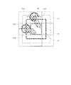
図3Aに、タッチパネル領域a1と入力領域a2と判別領域a3の中心を合わせ、判別領域a3を中心として8方向に分割した文字入力の配置の位置の説明図を例示する。タッチパネル領域a1、入力領域a2、判別領域a3は、図2A−2Cで説明した。図3Aの説明図において、破線により区分された各領域c1−c9には、入力の開始文字が配置される。配置する開始文字の大きさは入力領域a2を含んでいれば、入力領域a2をはみ出して大きくても構わない。また、c5の領域は判別領域a3に対応する。
(Character input operation)
FIG. 3A illustrates an explanatory view of the positions of character input arrangements obtained by aligning the centers of the touch panel area a1, the input area a2, and the determination area a3, and dividing the input area into eight directions around the determination area a3. The touch panel area a1, the input area a2, and the determination area a3 have been described with reference to FIGS. 2A-2C. In the explanatory diagram of FIG. 3A, an input start character is arranged in each of the regions c1 to c9 divided by a broken line. As long as the size of the start character to be arranged includes the input area a2, it may be larger than the input area a2. The area c5 corresponds to the discrimination area a3.
携帯電話機やスマートフォン等の文字入力に係る入力インターフェースは、例えば、8方向に区分された領域c1−c4、c6−c9から開始される“2段階フリック”、及び、中央の領域c5を開始位置とした“1段階フリック”を組合せることで表現できる。 An input interface related to character input such as a mobile phone or a smartphone has, for example, a “two-step flick” started from areas c1 to c4 and c6 to c9 divided into eight directions, and a center area c5 as a start position. It can be expressed by combining the “one-step flick”.
図3Bに、50音表の“あかさたなはまやらわ”といった各行の「あ」の段が配置された仮名文字入力の配置例を例示する。図3Bに例示の文字入力の配置では、9分割された領域c1−c9のそれぞれに、“あかさたなはまやらわ”の各行の「あ」の段が配置されている。但し、文字入力の配置は、図3B以外の配置であってもよい。 FIG. 3B exemplifies an arrangement example of kana character input in which “A” column of each row such as “Akasana Hamayarawa” in the 50-sound table is arranged. In the character input layout illustrated in FIG. 3B, the “A” level of each row of “Akasana Hamawara” is arranged in each of the nine divided areas c1 to c9. However, the arrangement of character input may be an arrangement other than that shown in FIG. 3B.
図3Bの例では、中央の領域c5には、文字「な」が配置されている。中央の文字「な」に対し、左上方向の領域c1には文字「あ」、上方向の領域c2には文字「か」、右上方向の領域c3には文字「さ」の、左方向の領域c4には文字「た」が配置されている。同様にして、中央の文字「な」に対し、右方向の領域c6には文字「は」、左下方向の領域c7には文字「ま」、下方向の領域c8には文字「や」と「わ」が配置されている。中央の文字「な」に対し、右下方向の領域c9には文字「ら」が配置されている。但し、かな文字の入力文字の配置が図3Bに限定されるわけではない。 In the example of FIG. 3B, the character “NA” is arranged in the central region c5. For the center character “NA”, the character “a” in the upper left region c1, the character “ka” in the upper region c2, the character “sa” in the upper right region c3, the left region The character “ta” is arranged in c4. Similarly, with respect to the central character “na”, the character “ha” is in the right region c6, the character “ma” is in the lower left region c7, and the characters “ya” and “ "Wa" is arranged. The character “ra” is arranged in the area c9 in the lower right direction with respect to the central character “na”. However, the arrangement of the input characters of the kana characters is not limited to FIG. 3B.
仮名文字以外の“ABC”等の英文字の場合であっても、同様にして、9分割された領域c1−c9に英文字を配置することができる。図3Cに、9分割された領域c1−c9に英文字の配置例を例示する。 Even in the case of English characters such as “ABC” other than kana characters, English characters can be similarly arranged in the nine-divided areas c1-c9. FIG. 3C illustrates an arrangement example of English characters in the nine divided areas c1 to c9.
図3Cの例では、中央の領域c5には、英文字「J」が配置されている。中央の領域c
5に対し、左上方向の領域c1には「.」等の特殊記号、上方向の領域c2には英文字「A」、右上方向の領域c3には文字「D」、左方向の領域c4には文字「G」が配置されている。同様にして、中央の領域c5に対し、右方向の領域c6には英文字「M」、左下方向
の領域c7には英文字「P」、下方向の領域c8には英文字「T」が配置されている。中央の領域c5に対し、右下方向の領域c9には英文字「W」が配置されている。但し、英文
字の入力文字の配置が図3Cに限定されるわけではない。
In the example of FIG. 3C, the letter “J” is arranged in the central region c5. Center area c
5 is a special symbol such as “.” In the upper left area c1, an English character “A” in the upper area c2, a letter “D” in the upper right area c3, and a left area c4. The letter “G” is placed. Similarly, with respect to the central region c5, the English character “M” is present in the right region c6, the English character “P” is present in the lower left region c7, and the English character “T” is present in the lower region c8. Has been placed. The letter “W” is arranged in the area c9 in the lower right direction with respect to the center area c5. However, the arrangement of English input characters is not limited to FIG. 3C.
以下、図3Bに例示の仮名文字の文字入力を対象として文字入力操作についての説明を行う。 Hereinafter, the character input operation will be described for the character input of the kana characters illustrated in FIG. 3B.
(2段階フリック)
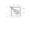
図3Dに、2段階フリックを用いた入力操作の説明図を例示する。なお、図3Dにおいて、文字入力の配置Tb1は、図3Bに例示の仮名文字入力の文字入力の配置を表す。また、Tb2は「あ」行の入力と特定した後の「あ」行の各段を十字方向に配置した例を表す。また、放射状の破線V1、V2は、図2Fに例示した8方向に分割された場合の移動方向の角度範囲であり、Tb1の文字「あ」からの操作開始時の移動方向をV1、Tb2
の文字「あ」からの操作開始時の移動方向をV2として表す。また、図3Aと同様にタッチパネル領域a1、入力領域a2、判別領域a3として表す。
(2 stage flick)
FIG. 3D illustrates an explanatory diagram of an input operation using a two-stage flick. In FIG. 3D, the character input layout Tb1 represents the character input layout of the kana character input illustrated in FIG. 3B. Further, Tb2 represents an example in which each stage of the “A” row after the input of the “A” row is arranged in the cross direction. Further, the radial broken lines V1 and V2 are the angular ranges of the movement direction when divided into the eight directions illustrated in FIG. 2F, and the movement directions at the start of the operation from the character “A” of Tb1 are V1 and Tb2.
The moving direction at the start of the operation from the character “A” is represented as V2. In addition, as in FIG. 3A, they are represented as a touch panel area a1, an input area a2, and a determination area a3.
図3Dに例示の説明図において、文字「あ」が配置された領域から判別領域a3に向かうフリック操作w6が発生したとする。2段階フリックのフリック操作w6では、左上の領域を開始位置とし入力領域a2を先に通り、中央の判別領域a3を停止位置とする軌跡が検出される。情報処理装置10は、例えば、Tb1の文字「あ」の領域から判別領域a3の領域に向かうフリック操作w6を検出して、2段階フリックの1段階目として判断する。右下に向かう移動方向からブロックP1に示すように、「あ」行に対する文字入力操作と特定する。
In the explanatory diagram illustrated in FIG. 3D, it is assumed that the flick operation w6 from the area where the character “A” is arranged to the determination area a3 occurs. In the two-step flick operation w6, a trajectory is detected in which the upper left area is the start position, the input area a2 is passed first, and the center discrimination area a3 is the stop position. For example, the
検出されたフリック操作w6が「あ」行に対する文字入力操作と特定した情報処理装置10は、例えば、文字入力の配置をTb1からTb2に切り替える。図3Dの文字入力の配置Tb2は、例えば、「あ」行の各段を十字方向に配置した例である。文字入力の配置Tb2では、中央の領域に対し、上方向の領域に文字「う」、下方向の領域に文字「お」、左方向の領域に文字「い」、右方向の領域に文字「え」が配置される。なお、中央の領域には、例えば、文字「あ」が配置されている。
The
フリック操作w6に継続してフリック操作w7が発生したとする。フリック操作w7では、中央の領域を開始位置とし、上方向の領域を終了位置とする軌跡が検出される。情報処理装置10は、例えば、中央の判別領域a3から上方向の領域に向かうフリック操作w7を検出し、「あ」行に含まれる文字項目の「う」を特定する。情報処理装置10は、2段階フリックで文字項目群の「あ」行を特定し、特定した文字項目群の中から文字項目「う」の特定を行う。特定された文字「う」は、例えば、文字入力処理に係るアプリケーションプログラム(以下、アプリとも称す)に入力文字として反映される。
It is assumed that a flick operation w7 occurs following the flick operation w6. In the flick operation w7, a locus having the center area as the start position and the upper area as the end position is detected. For example, the
なお、文字入力の配置Tb2では、例えば、「あ」行に含まれる文字項目の「あ」を特定する場合には、判別領域a3で停止させた操作指等をタッチパネルから離脱させればよい。文字入力の配置Tb2では、「あ」行に含まれる各文字は、中央の領域を含む十字方向に配置した。しかし、例えば、「あ」行の各文字は、左上方向の領域に「あ」、上方向の領域に「い」、右上方向の領域に「う」、左方向の領域に「え」、右方向の領域に「お」を配置する扇形としてもよい。少なくとも、文字入力の配置は、中央の領域で停止させたフリック操作w6に継続して実行されるフリック操作の移動方向を特定できればよい。 In the character input layout Tb2, for example, when the character item “A” included in the “A” line is specified, the operating finger or the like stopped in the determination area a3 may be detached from the touch panel. In the character input layout Tb2, the characters included in the "A" line are arranged in a cross direction including the center area. However, for example, each character in the “A” line is “A” in the upper left area, “I” in the upper area, “U” in the upper right area, “E” in the left area, It is good also as a sector shape which arranges "o" in the area | region of a direction. At least the arrangement of character input need only be able to identify the direction of movement of the flick operation that is performed following the flick operation w6 stopped in the center area.
上記のように、情報処理装置10は、2段階フリックにより、文字項目群といった情報の項目群を特定し、特定した項目群から入力項目を特定できる。
As described above, the
(1段階フリック)
図3Eに、1段階フリックを用いた入力操作の説明図を例示する。なお、図3Eの文字入力の配置Tb1は、図3Bに例示の仮名文字入力の文字入力の配置を表す。また、Tb3は「な」行の入力と特定した後の「な」行の各段を十字方向に配置した例を表す。また、放射状の破線V1、V2は、図2Fに例示した8方向に分割された場合の移動方向の角度範囲であり、Tb1の文字「な」からの操作開始時の移動方向をV1、Tb3の文字「な」からの操作開始時の移動方向をV2として表す。
(1 stage flick)
FIG. 3E illustrates an explanatory diagram of an input operation using a one-step flick. The character input layout Tb1 in FIG. 3E represents the character input layout of the kana character input illustrated in FIG. 3B. Tb3 represents an example in which each row of the “na” row after being identified as an input of the “na” row is arranged in the cross direction. Further, the radial broken lines V1 and V2 are the angular ranges of the movement direction when divided into the eight directions illustrated in FIG. 2F, and the movement direction at the start of the operation from the character “NA” of Tb1 is V1 and Tb3. The moving direction at the start of the operation from the character “NA” is represented as V2.
文字入力の配置Tb1で「な」行の文字入力が行われる場合には、文字「な」が配置された判別領域a3内に対するタッチ操作w8が検出される。情報処理装置10は、例えば、文字「な」が表示された領域への接触を検出し、ブロックP2に示すように、「な」行に対する文字入力操作と特定する。そして、情報処理装置10は、判別領域a3内を開始位置とするフリック操作を検出し、「な」行に含まれる文字候補を特定する。
When the character input on the “NA” line is performed in the character input arrangement Tb1, the touch operation w8 in the determination area a3 in which the character “NA” is arranged is detected. For example, the
検出されたタップ操作w8が「な」行に対する文字入力操作と特定した情報処理装置10は、例えば、文字入力の配置をTb1からTb3に切り替える。図3Eの文字入力の配置Tb3は、例えば、「な」行の各段を十字方向に配置した入力文字の配置例である。文字入力の配置Tb3では、中央の領域に対し、上方向の領域に文字「ぬ」、下方向の領域に文字「の」、左方向の領域に文字「に」、右方向の領域に文字「ね」が配置される。なお、中央の領域には、例えば、文字「な」が配置されている。
The
タッチ操作w8の検出後、継続して中央の判別領域a3内を開始位置とするフリック操作w9が発生したとする。フリック操作w9では、中央の判別領域a3内を開始位置とし、上方向の領域を終了位置とする軌跡が検出される。情報処理装置10は、例えば、中央
の判別領域a3内から上方向の領域に向かうフリック操作w9を検出し、「な」行に含まれる文字候補の「ぬ」を特定する。情報処理装置10は、判別領域a3内から開始するタッチ操作で文字項目群の「な」行を特定する。そして、継続する中央の判別領域a3内を開始位置とするフリック操作w9(1段階フリック)で、特定した文字項目群の中から文字項目「ぬ」の特定を行う。特定された文字「ぬ」は、例えば、文字入力処理に係るアプリに入力文字として反映される。
It is assumed that after the touch operation w8 is detected, a flick operation w9 that continues in the center discrimination area a3 is generated. In the flick operation w9, a trajectory having a start position in the center discrimination area a3 and an end position in the upper area is detected. For example, the
上記のように、情報処理装置10では、中央の判別領域a3内から開始するタッチ操作により、文字項目群の中から対象となる文字候補を含む項目を特定する。そして、情報処理装置10では、継続する中央の判別領域a3内を開始位置とする1段階フリックにより、対象となる文字候補(入力項目)が特定される。
As described above, in the
なお、文字入力の配置Tb3の例で、「な」行に含まれる文字候補の「な」を特定する場合には、例えば、タッチ操作で中央の判別領域a3内に接触させた操作指等をフリック操作せずにタッチパネルから離脱させればよい。 In the example of the character input arrangement Tb3, when the character candidate “NA” included in the “NA” line is specified, for example, an operation finger or the like brought into contact with the center discrimination region a3 by a touch operation is used. What is necessary is just to make it detach | leave from a touch panel, without performing a flick operation.
文字入力の配置Tb3では、中央の領域を含む十字方向に「な」行の各文字を配置した。しかし、例えば、左上方向の領域に「な」、上方向の領域に「に」、右上方向の領域に「ぬ」、左方向の領域に「ね」、右方向の領域に「の」を配置する扇形としてもよい。この場合であっても、情報処理装置10は、中央の領域を開始位置とした、1段階フリックによる移動方向に基づいて対象となる文字候補を特定できる。
In the character input layout Tb3, the characters in the “NA” line are arranged in the cross direction including the center area. However, for example, “na” is placed in the upper left area, “ni” in the upper area, “nu” in the upper right area, “ne” in the left area, and “no” in the right area. It may be a fan shape. Even in this case, the
また、判別領域a3外から判別領域a3外への1段階フリックでは、例えば、「濁点、半濁点、小文字」等の文字修飾、仮名文字から英文字等の文字種別の変更を行う入力モードの切り替えなどの操作として特定させることが可能である。上記の文字修飾や入力モードの変更等の1段階フリックは、次のフリック操作で特定することができる。 In addition, in a one-step flick from the outside of the discrimination area a3 to the outside of the discrimination area a3, for example, character modification such as “dakuten, semi-dakuten, lowercase”, and switching of the input mode for changing the character type from kana characters to English characters etc. It is possible to specify as such operation. One-step flicks such as the above character modification and input mode change can be specified by the next flick operation.
すなわち、フリック操作は、判別領域a3外の入力領域a2をフリック操作の開始位置とする。そして、フリック操作で移動させた操作指等の離脱位置は、開始位置とは異なる判別領域a3外の入力領域a2とすればよい。なお、フリック操作において、判別領域a3内を通過する場合には、判別領域a3内で停止することなく判別領域a3外の入力領域a2に移動するとすればよい。 That is, in the flick operation, the input area a2 outside the determination area a3 is set as the start position of the flick operation. Then, the separation position of the operation finger or the like moved by the flick operation may be set to the input area a2 outside the determination area a3 different from the start position. In the flick operation, when the vehicle passes through the determination area a3, it is only necessary to move to the input area a2 outside the determination area a3 without stopping in the determination area a3.
以下に、上記の文字修飾や入力モードの変更等に係る1段階フリックの一例を例示する。文字修飾の対象となる文字は、直前に操作入力された文字である。
・濁点修飾:情報処理装置10は、判別領域a3外の領域を1段階フリックの接触開始位置とし、右下方向に移動させて判別領域a3外で離脱するタッチ操作を検出する。直前に操作入力された文字が「は」の場合には、当該の1段階フリックで濁点文字「ば」に置き換えられる。
・半濁点修飾:情報処理装置10は、判別領域a3外の領域を1段階フリックの接触開始位置とし、右上方向に移動させて判別領域a3外で離脱するタッチ操作を検出する。直前に操作入力された文字が「は」の場合には、当該の1段階フリックで半濁点文字「ぱ」に置き換えられる。
・小文字修飾:情報処理装置10は、判別領域a3外の領域を1段階フリックの接触開始位置とし、下方向に移動させて判別領域a3外で離脱するタッチ操作を検出する。直前に操作入力された文字が「つ」の場合には、当該の1段階フリックで小文字「っ」に置き換えられる。
・文字削除:情報処理装置10は、判別領域a3外の領域を1段階フリックの接触開始位置とし、左方向に移動させて判別領域a3外で離脱するタッチ操作を検出する。直前に操作入力された文字が削除される。
・入力モード切替:情報処理装置10は、判別領域a3外の領域を1段階フリックの接触開始位置とし、右方向に移動させて判別領域a3外で離脱するタッチ操作を検出する。なお、入力モードは、例えば、かな漢字→英数字→かな漢字→…、等のように操作の度に順次切り替えられる。
An example of a one-step flick related to the above-described character modification, input mode change, and the like will be described below. The character that is the target of character modification is the character that was input immediately before.
Turbidity modification: The
-Semi-turbid point modification: The
Lower-case decoration: The
Character deletion: The
Input mode switching: The
図3Fに、1段階フリックを用いた文字の削除操作の説明図を例示する。文字の削除操作では、判別領域a3外から判別領域a3外への1段階フリックが行われる。なお、図3Fの文字入力の配置Tb1は、図3Bに例示の仮名文字入力の文字入力の配置を表す。また、放射状の破線V1は、図2Fに例示した8方向に分割された場合の移動方向の角度範囲であり、タッチ操作の開始時の移動方向を表す。 FIG. 3F illustrates an explanatory diagram of a character deletion operation using a one-step flick. In the character deletion operation, a one-step flick from the outside of the discrimination area a3 to the outside of the discrimination area a3 is performed. The character input layout Tb1 in FIG. 3F represents the character input layout of the kana character input illustrated in FIG. 3B. Moreover, the radial broken line V1 is an angle range of the moving direction when divided into the eight directions illustrated in FIG. 2F and represents the moving direction at the start of the touch operation.
1段階フリックを用いた文字の削除操作が行われる場合には、判別領域a3外の領域を開始位置とするフリック操作w10が検出される。フリック操作w10は、左の方向に移動し、判別領域a3を通過し、判別領域a3外の領域で離脱する。フリック操作w10では、例えば、判別領域a3外の右側領域を開始位置とし、判別領域a3外の左側領域を離脱位置とする軌跡が検出される。情報処理装置10は、例えば、判別領域a3を右側から左方向に通過する1段階フリックを検出し、直前に入力された文字項目の削除処理を行う。
When a character deletion operation using a one-step flick is performed, a flick operation w10 starting from an area outside the determination area a3 is detected. The flick operation w10 moves in the left direction, passes through the discrimination area a3, and leaves in the area outside the discrimination area a3. In the flick operation w10, for example, a trajectory having the right region outside the determination region a3 as a start position and the left region outside the determination region a3 as a separation position is detected. For example, the
本実施形態の情報処理装置10は、判別領域a3外から判別領域a3内へのフリック操作に伴う移動方向に基づいて入力対象となる情報の項目群、入力項目を特定することができる。同様にして、情報処理装置10は、判別領域a3内から判別領域a3外へのフリック操作に伴う移動方向、判別領域a3外から判別領域a3外へのフリック操作に伴う移動方向に基づいて、入力対象となる情報の項目群、入力項目を特定することができる。本実施形態の情報処理装置10のタッチパネルは、例えば、判別領域a3と該判別領域a3の外周領域とを区分けし、移動した際の方向を特定できる座標精度があればよい。
The
図3Gに、本実施形態の入力インターフェースについての説明図を例示する。図3Gに例示のフリック操作w11、w12は、判別領域a3外の領域を開始位置とし、判別領域a3内を離脱位置とするタッチ操作であり、移動方向D1と移動方向D2は図2Fにおける「右下」の範囲となる。また、フリック操作w11、w12は、例えば、図3Aに例示の、c2、c4から開始されるが、右下方向へ移動した後、判定領域a3で停止するフリック操作とする。なお、右下方向に対応する角度の範囲は基準軸Xsの右方向を“0°”とすると、“292.5°”以上−“337.5°”未満である。 FIG. 3G illustrates an explanatory diagram of the input interface of the present embodiment. The flick operations w11 and w12 illustrated in FIG. 3G are touch operations in which the area outside the determination area a3 is a start position and the determination area a3 is a disengagement position. The movement direction D1 and the movement direction D2 are “right” in FIG. “Lower” range. The flick operations w11 and w12 are, for example, started from c2 and c4 illustrated in FIG. 3A, but are flick operations that stop in the determination area a3 after moving in the lower right direction. Note that the angle range corresponding to the lower right direction is “292.5 °” or more and less than “337.5 °” when the right direction of the reference axis Xs is “0 °”.
本実施形態の情報処理装置10では、フリック操作w11、w12のそれぞれを、例えば、図3Bに例示の文字入力の、「あ」行に対する操作入力と特定することができる。情報処理装置10では、接触位置の移動方向を検出するので、文字領域が狭小な場合であっても誤入力が抑制される。このため、図3Bに例示の文字の、文字「あ」に隣接する文字「か」、「た」が配置された領域で接触開始が発生しても、情報処理装置10は、誤入力を抑制することができる。情報処理装置10は、例えば、隣接する操作オブジェクトへの誤接触が発生しやすい狭小なタッチパネルでも押し間違え等を抑制できる。
In the
また、例えば、フリック操作の移動速度を100mm/sec以下とし、接触位置を検出するためのサンプリング周期を20ms以内と想定する。このケースでは、例えば、4mm以上の幅があれば、少なくともフリック操作の2点の座標が検出可能となる。 Further, for example, it is assumed that the moving speed of the flick operation is 100 mm / sec or less and the sampling period for detecting the contact position is within 20 ms. In this case, for example, if there is a width of 4 mm or more, the coordinates of at least two points of the flick operation can be detected.
指のデバイス面に対する接触面積を直径7mmと想定すると、判別領域a3は、直径7mmの接触面を含めることで、判別領域内からのフリック操作による移動を検出することが可能となる。一例として、直径7mmの接触面積の部分を内包でき、フリック操作の移
動検出が可能な7mm×7mmの矩形領域を判別領域a3とする。なお、指などの接触面は一般に楕円形をしており、タッチパネルはその中心点を座標として検出する。
Assuming that the contact area of the finger with respect to the device surface is 7 mm in diameter, the discrimination region a3 can detect the movement by the flick operation from within the discrimination region by including the contact surface with a diameter of 7 mm. As an example, a 7 mm × 7 mm rectangular area that can include a contact area portion having a diameter of 7 mm and that can detect a movement of a flick operation is set as a determination area a3. Note that a contact surface such as a finger is generally elliptical, and the touch panel detects the center point as coordinates.
図3Hに、7mm×7mmの矩形領域を判別領域a3とした場合の説明図を例示する。なお、図3Hは、タッチパネル領域a1、入力領域a2、判別領域a3の形状をそれぞれ矩形状とした場合の例である。また、図3Hは、タッチパネル領域a1、入力領域a2、判別領域a3のそれぞれの中心位置を共通にして同心状に設定された場合の一例である。 FIG. 3H illustrates an explanatory diagram when a 7 mm × 7 mm rectangular area is set as the determination area a3. FIG. 3H shows an example in which the touch panel area a1, the input area a2, and the discrimination area a3 are each rectangular. FIG. 3H is an example of a case where the center positions of the touch panel area a1, the input area a2, and the discrimination area a3 are set concentrically in common.
図3Hに例示のように、7mm×7mmの矩形領域を判別領域a3として、判別領域a3と入力領域a2の外周の間隔は、最短で4mmの幅とする。タッチパネル領域a1と入力領域a2が一致する場合、タッチパネル領域a1のサイズは、例えば、15mm×15mm以上であればよい。このため、例えば、腕時計程度の狭小なタッチパネル領域a1であっても、フリック操作w13、タップ操作w14等の指を用いたタッチ操作で情報入力を行うことが可能となる。タッチパネルに重畳した表示デバイスが表示する情報は、操作する指に隠れて見難くなるが、入力領域a2の範囲を目視により確認することで、判別領域a3の位置を推定できる為、移動方向を伴うフリック操作、定点タッチ等による操作入力は可能である。 As illustrated in FIG. 3H, a rectangular area of 7 mm × 7 mm is set as a determination area a3, and the distance between the outer periphery of the determination area a3 and the input area a2 is 4 mm at the shortest. When the touch panel area a1 and the input area a2 match, the size of the touch panel area a1 may be, for example, 15 mm × 15 mm or more. For this reason, for example, even in a touch panel region a1 as narrow as a wristwatch, it is possible to input information by a touch operation using a finger such as a flick operation w13 and a tap operation w14. The information displayed by the display device superimposed on the touch panel is difficult to see because it is hidden behind the operating finger, but the position of the discrimination area a3 can be estimated by visually confirming the range of the input area a2, and therefore the movement direction is accompanied. Operation input by flick operation, fixed point touch, etc. is possible.
また、本実施形態の情報処理装置10では、従来の10キー配列といった入力インターフェースに対し、8方向+1(中央タッチ)の判別で操作入力が可能となる。このため、10キー配列の操作オブジェクトを表示し、トグル方式で入力項目を決定する場合と比べ短い操作手順での入力が可能となる。本実施形態の情報処理装置10は、狭小なタッチパネルを用いた指操作による情報入力の操作性を向上することができる。
Further, in the
〔装置構成〕
図1に戻り、本実施形態の情報処理装置10は、接続バスB1によって相互に接続されたCPU(Central Processing Unit)11、主記憶部12、補助記憶部13、入力部1
4、出力部15、通信部16を有する。なお、図1は、パーソナルコンピュータといった情報処理装置の一般的なハードウェアの構成例である。主記憶部12及び補助記憶部13は、情報処理装置10が読み取り可能な記録媒体である。
〔Device configuration〕
Returning to FIG. 1, the
4, an
情報処理装置10は、CPU11が補助記憶部13に記憶されたプログラムを主記憶部12の作業領域に実行可能に展開し、プログラムの実行を通じて周辺機器の制御を行う。これにより、情報処理装置10は、上述した所定の目的に合致した機能を実現することができる。
In the
図1に例示の情報処理装置10において、CPU11は、情報処理装置10全体の制御を行う中央処理演算装置である。CPU11は、補助記憶部13に格納されたプログラムに従って処理を行う。主記憶部12は、CPU11がプログラムやデータをキャッシュしたり、作業領域を展開したりする記憶媒体である。主記憶部12は、例えば、RAM(Random Access Memory)やROM(Read Only Memory)を含む。
In the
補助記憶部13は、各種のプログラム及び各種のデータを読み書き自在に記録媒体に格納する。補助記憶部13は、外部記憶装置とも呼ばれる。補助記憶部13には、OS、各種プログラム、各種テーブル等が格納される。OSは、例えば、搭載されたアプリに対し、管理するリソースへのインターフェースをアプリに提供する。
The
情報処理装置10に搭載されたアプリは、OSによって提供されたリソースへのインターフェースを使用することで、アプリ機能を実現する。OSは、通信部16を介して接続される外部装置等とのデータの受け渡しを行う通信インターフェースプログラムを含む。
外部装置等には、例えば、図示しないネットワーク上の、PCやサーバ等の他の情報処理装置、外部記憶装置等が含まれる。
An application installed in the
Examples of the external device include other information processing devices such as a PC and a server, an external storage device, and the like on a network (not shown).
補助記憶部13は、例えば、EPROM(Erasable Programmable ROM)、ソリッドス
テートドライブ装置、ハードディスクドライブ(HDD、Hard Disk Drive)装置等であ
る。また、補助記憶部13としては、例えば、CDドライブ装置、DVDドライブ装置、BDドライブ装置等が提示できる。記録媒体としては、例えば、不揮発性半導体メモリ(フラッシュメモリ)を含むシリコンディスク、ハードディスク、CD、DVD、BD、USB(Universal Serial Bus)メモリ、メモリカード等がある。
The
入力部14は、ユーザ等からの操作指示等を受け付ける。入力部14は、カメラ、入力ボタン、タッチセンサ14a、ポインティングデバイス、マイクロフォン等の入力デバイスである。入力部14には、キーボード、ワイヤレスリモコン等が含まれるとしてもよい。ポインティングデバイスには、例えば、タッチセンサ14a(タッチパネル)マウス、トラックボール、ジョイスティック等が含まれる。入力部14から入力された情報は、接続バスB1を介してCPU11に通知される。例えば、ポインティングデバイスで検出した座標情報は、接続バスB1を介してCPU11に通知される。
The
出力部15は、CPU11で処理されるデータや主記憶部12に記憶されるデータを出力する。出力部15は、LCD15a、CRT(Cathode Ray Tube)ディスプレイ、PDP(Plasma Display Panel)、EL(Electroluminescence)パネル、有機ELパネル等
の表示デバイスを含む。また、出力部15には、プリンタ、スピーカ等の出力デバイスが含まれる。
The
通信部16は、例えば、情報処理装置10が接続するネットワーク等とのインターフェースである。ネットワークには、例えば、インターネット等の公衆ネットワーク、携帯電話網等の無線ネットワーク、LAN(Local Area Network)、USB(Universal Serial
Bus)等が含まれる。
The
Bus) etc. are included.
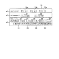
〔コンピュータプログラム構成〕
図4に、情報処理装置10のコンピュータプログラムの構成を例示する。情報処理装置10の中央処理演算装置(CPU11)は、コンピュータプログラムにより本実施形態の処理を実行する。以下、中央処理演算装置(CPU11)が、図4の各プログラムにより処理を実行することを、単に、プログラムが処理を実行するともいう。
[Computer program structure]
FIG. 4 illustrates the configuration of the computer program of the
図4に例示のように、情報処理装置10のコンピュータプログラムは、例えば、アプリ(application)を実行する階層e1、OSのフレームワーク(framework)として機能する階層e2、OSのカーネル(kernel)として機能する階層e3を含む。階層e1のアプリ(A)20a、アプリ(B)20b、アプリ20cは、例えば、情報処理装置10に搭載された文字入力アプリ、表計算アプリ、ブラウザアプリ等である。各アプリは、OSによって提供されたリソースへのインターフェースを使用することで、それぞれのアプリ機能を提供する。
As illustrated in FIG. 4, the computer program of the
階層e2は、各アプリと階層e3のカーネルとの間のインターフェースとして機能するOS領域である。階層e2は、例えば、各アプリで使用されるAPI(Application Programming Interface)、汎用ライブラリ等を含む。階層e2には、アプリ入力補助21、
入力判定22が含まれる。
The hierarchy e2 is an OS area that functions as an interface between each application and the kernel of the hierarchy e3. The hierarchy e2 includes, for example, an API (Application Programming Interface) used by each application, a general-purpose library, and the like. In the hierarchy e2,
An
アプリ入力補助21は、例えば、入力判定22で判定された入力文字等の情報をアプリに引き渡す。入力判定22は、例えば、入力領域a2等で検出されたタッチ操作の接触位
置、離脱位置等に基づいてタッチ操作の種類、移動方向等を判定する。そして、入力判定22は、例えば、判定された上記項目に基づいて対応する入力文字等の情報を特定する。入力判定22により特定された情報はアプリ入力補助21に引き渡される。
For example, the
階層e3は、例えば、情報処理装置10のリソースを管理するOS領域である。階層e3により、階層e2を介して通知された情報に基づいて、リソースに対するプロセス管理、メモリ管理、デバイス管理等が行われる。情報処理装置10では、階層e3の機能により、アプリの実行に伴う各種デバイスへの入出力、メモリへのデータの読み書き各種プロセスの実行や停止等を行うことができる。
The hierarchy e3 is an OS area that manages resources of the
階層e3は、例えば、RAM管理部23、タイマ制御24、入力制御25、表示制御26、FileSystem27、電源制御28、タッチセンサ制御29、LCD制御30、補助記憶部制御31を含む。RAM管理部23は、例えば、文字入力処理に伴う主記憶部12へのデータの格納、格納されたデータの読み出し等を行う。タイマ制御24は、例えば、文字入力処理に伴う時間計測のタイマを制御する。
The hierarchy e3 includes, for example, a
入力制御25は、例えば、文字入力処理に伴う、入力部14の入力デバイス介して入力された入力データの制御を行う。表示制御26は、例えば、文字入力処理で特定された入力文字、文字入力処理に伴う表示制御を行う。FileSystem27は、例えば、補助記憶部13の各種データファイルを管理する。電源制御28は、例えば、情報処理装置10のバッテリ等の電源の管理制御を行う。タッチセンサ制御29は、例えば、文字入力処理に伴うタッチセンサ14aの制御を行う。LCD制御30は、例えば、LCD15a等に表示される表示データの表示制御を行う。補助記憶部制御31は、例えば、文字入力処理に伴う、補助記憶部13のデータの格納、格納されたデータの読み出しを行う。
The
〔タイムチャート〕
図5に、文字入力処理に係るタイムチャートを例示する。図5に例示のタイムチャートでは左右方向は時間軸を表し、上下方向は図4に例示の各コンピュータプログラムの項目を表す。図5の例では、アプリ20a、アプリ入力補助21、入力判定22、入力制御25、タッチセンサ制御29の各コンピュータプログラムが含まれる。なお、情報処理装置10では、例えば、情報処理装置10の電源投入と共に、タッチセンサ14aで検出された物理量の変化に伴う座標が一定周期でタッチセンサ制御29に通知されている。タッチセンサ制御29は、タッチセンサ14aから通知された座標を入力制御25に引き渡す。
〔Time chart〕
FIG. 5 illustrates a time chart relating to the character input process. In the time chart illustrated in FIG. 5, the left-right direction represents the time axis, and the up-down direction represents the items of each computer program illustrated in FIG. In the example of FIG. 5, computer programs of the
図5に例示のタイムチャートにおいて、文字入力処理の開始f1は、例えば、アプリ20aの起動のときが例示できる。アプリ入力補助21、入力判定22は、アプリ20aの起動後に実行されるプログラムからの読み出し要求等に基づいて、上記の処理を実行する。アプリ入力補助21、入力判定22は、アプリ20aの終了f4のときまで継続される。
In the time chart illustrated in FIG. 5, the start f1 of the character input process can be illustrated, for example, when the
図5に例示のタイムチャートにおいて、例えば、入力判定22で特定された入力文字は、アプリ入力補助21を介し、アプリ20aに通知される(f2、f3)。アプリ20aに通知された入力文字は、入力文字を表示する表示領域に表示される。
In the time chart illustrated in FIG. 5, for example, the input character specified by the
入力判定22は、例えば、文字入力処理の開始f1から終了f4に至るまでの期間の、タッチ操作についての座標を入力制御25を介して受け付ける。受け付けた座標は、例えば、主記憶部12の所定の領域に時系列順に一時的に記憶される。受け付けた座標の記憶は、例えば、階層e3のRAM管理部24等を介して行われる。
The
また、入力判定22は、例えば、入力領域a2に発生した操作指による接触(g2)を
検出した入力制御25からの通知(f10)により、入力文字判定処理を開始する。入力判定22は、例えば、入力領域a2で発生した接触位置の時系列データ(f10〜f14、f15〜f16)から、フリック操作に伴う移動を検出する。入力判定22は、例えば、接触位置の時系列データ(f10〜f12)に基づく軌跡からタッチ操作(g2〜g4)が、判別領域a3外の周辺領域から判別領域a3内に向かうフリック操作であることを検出する(f5)。
In addition, the
入力判定22は、例えば、フリック操作の移動方向に基づいて入力文字の属する文字項目の特定を行う(f5)。
In the
入力判定22は、例えば、文字項目の特定後、継続するフリック操作の移動を検出する。入力判定22は、例えば、接触位置の時系列データ(f12〜f14)に基づく軌跡から継続するタッチ操作(g4〜g6)が、判別領域a3内から判別領域a3外の周辺領域に向かうフリック操作であることを検出する(f6)。また、入力判定22は、フリック操作による接触の開始位置と離脱位置から、移動方向を特定する。
The
入力判定22は、例えば、フリック操作の移動方向に基づいて入力文字の特定を行い、特定した入力文字をアプリ入力補助21に通知する(f7)。入力判定22における入力文字、および、入力文字が属する項目を特定する入力文字判定処理は、文字単位で終了する。特定された入力文字は、文字単位の入力文字判定処理の終了と共に、アプリ入力補助21を介してアプリ20aに通知される(f2)。アプリ20aに通知された入力文字は、例えば、入力文字を表示する表示領域に表示される。
For example, the
以上の文字入力処理は、例えば、アプリ20aの終了のとき(f4)まで、入力領域a2に発生したタッチ操作に対して繰り返される。例えば、入力判定22は、前述のフリック操作の後に発生した判別領域a3内に対するタッチ操作(g7〜g8)の、接触位置の時系列データ(f8−f9)に基づいて、文字入力処理を行う。入力判定22は、例えば、時系列データ(f8−f9)から定点タッチを検出し(f8)、入力文字(f9)を特定し、特定した入力文字をアプリ入力補助21を介してアプリ20aに通知する(f3)。
The character input process described above is repeated for the touch operation generated in the input area a2 until, for example, the
なお、入力判定22では、接触位置を示す座標の時系列データの変化量(移動量)が所定の閾値(例えば、1mm以内)より小さい範囲で、一定時間(例えば、0.1秒)以上に停留する場合には、停止として判断する。また、文字項目の特定、および、文字項目に属する文字の特定は、アプリ入力補助21で行うとしてもよい。アプリ入力補助21で文字項目、入力文字の特定が行われる場合には、入力判定22は、判別領域a3を用いたタッチ操作の種類、移動方向等をアプリ入力補助21に通知するとすればよい。
In the
〔処理フロー〕
以下、図6に例示のフローチャートを参照し、本実施形態の情報処理装置10における文字入力処理を説明する。情報処理装置10は、例えば、主記憶部12に実行可能に展開されたコンピュータプログラムにより、図6に例示の文字入力処理を実行する。
[Process flow]
Hereinafter, the character input process in the
図6に例示のフローチャートにおいて、文字入力処理の開始は、例えば、情報処理装置10に搭載された文字入力処理に係るアプリ20aの起動のときが例示できる。情報処理装置10は、例えば、アプリ20aの起動後にアプリ入力補助21を起動し、引き続いて入力判定22を起動する。入力判定22は入力制御25から、タッチセンサ14aを介して検出されたタッチパネルの入力情報(座標情報、接触状態)を受け付ける(S1)。
In the flowchart illustrated in FIG. 6, the start of the character input process can be exemplified, for example, when the
情報処理装置10は、例えば、S1の処理で受け付けた入力情報に基づいて、入力領域
a2に発生した接触操作の開始を検出する(S2)。情報処理装置10は、例えば、S1の処理で取得した座標情報、接触状態情報と、現在の時刻情報をS4の処理に引き渡す。なお、情報処理装置10では、例えば、入力領域a2に発生した接触操作の開始を契機として入力文字判定処理が実行される(S3)。
For example, the
なお、S3−S33の処理で実行される入力文字判定処理については、例えば、文字入力モードは、初回は“かな漢字”とすることができる。2回目以降は、前回の入力文字判定処理の終了時の文字入力モードを引き継ぐとしてもよい。 In addition, about the input character determination process performed by the process of S3-S33, the character input mode can be set to "kana-kanji" for the first time, for example. After the second time, the character input mode at the end of the previous input character determination process may be taken over.
S4の処理では、情報処理装置10は、入力領域a2で発生したタッチ操作を判定するための初期設定を行う。例えば、情報処理装置10は、座標を記録する変数の前座標(x,y)にS2の処理から引き渡された座標(開始座標)を設定する。また、情報処理装置10は、経過時間を算出する為の変数の前時間“t”にS2の処理から引き渡された開始時間を設定する。
In the process of S4, the
また、S4の処理では、情報処理装置10は、初期設定として、例えば、移動方向を記録する変数の移動方向記録“V[1]”と移動方向記録“V[2]”に、例えば、“なし”を設定する。移動方向記録“V[1]”は、2段階フリックの1段目のフリック方向か、若しくは1段階フリックのフリック方向が記録される。同様にして、移動方向記録“V[2]”は、2段階フリックの2段目のフリック方向が記録される。なお、各フリック方向の記録は、S17,S18の処理で行われる。
Further, in the process of S4, the
さらに、S4の処理では、情報処理装置10は、初期設定として、例えば、移動方向フラグ“M”、停止フラグ“S”の値を0とする。ここで、移動方向フラグ“M”は、処理中のフリック操作についての移動方向を、移動方向記録“V[1]”と移動方向記録“V[
2]”のどちらに記録するかを示す変数であり、“V[M]”のように添え字に使用される
変数である。M=0の場合は、移動方向記録には何も記録されていない状態を表す。また、M=1の場合は、移動方向記録“V[1]”に2段階フリックの1段目か、若しくは1段階フリックの移動方向が記録されている状態を表す。同様にして、M=2の場合は、移動方向記録“V[2]”に2段階フリックの2段目の移動方向が記録されている状態を表す。
Furthermore, in the process of S4, the
2] ”, a variable used for subscripts such as“ V [M] ”. When M = 0, nothing is recorded in the moving direction recording. In addition, when M = 1, the movement direction record “V [1]” indicates a state where the first stage of the two-stage flick or the movement direction of the first-stage flick is recorded. Similarly, when M = 2, the movement direction recording “V [2]” represents a state in which the movement direction of the second stage of the two-stage flick is recorded.
また、停止フラグ“S”は、2段階フリックの1段目のフリックが開始されてから停止が発生したか否かを記録する変数である。S=0の状態はフリックが開始されてから停止が発生していないことを表し、S=1はフリックが開始されてから停止が発生したことを表す。 The stop flag “S” is a variable for recording whether or not a stop has occurred since the first flick of the two-step flick is started. The state of S = 0 represents that no stop has occurred since the flick was started, and S = 1 represents that the stop has occurred since the flick was started.
S5の処理では、例えば、情報処理装置10は、タッチ操作の開始座標を変数“B”に記録する。情報処理装置10は、例えば、変数“B”に記録された開始座標の座標値に基づいて、タッチ操作の開始位置が判別領域a3の内側領域あるいは外側領域であるかを判断する。なお、S5の処理において、情報処理装置10は、判別領域a3の内側領域あるいは外側領域であるかを判定し、変数“B”に記録するとしてもよい。例えば、情報処理装置10は、判別領域a3の内側領域である場合にはB=0、判別領域a3の外側領域である場合にはB=1といった2値の状態値をフラグ値として変数Bに記録することが例示できる。
In the process of S5, for example, the
S6の処理では、情報処理装置10は、例えば、20ms等の一定周期でサンプリングされた座標情報や接触状態をタッチセンサ14aから読み取った入力制御25からの情報(座標情報、接触状態)の通知待ちを行う。そして、情報処理装置10は、S2の処理で検出されたタッチ操作が継続しているかを判定する(S7)。
In the process of S6, the
情報処理装置10は、例えば、入力制御25から接触中であることを示す情報が通知された場合には(S7,yes)、S8の処理に移行する。また、情報処理装置10は、例えば、入力制御25から接触中ではないことを示す情報が通知された場合には(S7,No)、S21の処理に移行する。S21−S33の処理では、タッチ操作の種類、フリック操作の移動方向等に基づいて、入力文字の特定、文字入力モードの切り替え等が行われる。
For example, when information indicating that the user is in contact is notified from the input control 25 (S7, yes), the
S8の処理では、情報処理装置10は、例えば、S6の処理で通知された入力制御25からの情報(座標情報)と現在の時刻情報を取得する。そして、情報処理装置10は、例えば、取得した座標情報を、現在の接触位置を示す変数の座標(X,Y)に記録する。また、情報処理装置10は、例えば、取得した時刻情報を現在の時刻を示す変数である時間“T”に記録する。
In the process of S8, the
S9の処理では、情報処理装置10は、S8の処理で取得した現在の座標(X,Y)とS4の処理で設定した前座標(x,y)との差分値に基づいて、タッチ操作の移動の有無を判定する。移動の有無は、例えば、各座標成分の差分値が所定の閾値距離を超えることにより判定する。ここで、所定の閾値距離とは、定点タッチ、フリック操作を識別するための閾値である。例えば、定点タッチ操作とフリック操作を判別する閾値距離を仮決めしておき、移動を伴うフリック操作、定点タッチ操作などをユーザに試行させるなどして、各操作の検出率などを計測する。そして、計測された各操作の検出率などに基づいて、定点タッチ操作とフリック操作を判別する閾値距離を調整するようにしてもよい。
In the process of S9, the
S9の処理では、情報処理装置10は、例えば、S8の処理で取得した現在の座標(X,Y)とS4の処理で設定した前座標(x,y)とが、次に示す関係にあることを判定する。すなわち、情報処理装置10は、“|X−x|>閾値距離”であること、或いは、“|Y−y|>閾値距離”であることを判定する。情報処理装置10は、例えば、“|X−x|>閾値距離”、或いは、“|Y−y|>閾値距離”である場合には(S9,Yes)、S10の処理に移行する。S10の処理では、移動がなされたとして前時間“t”を現在の時刻“T”の値に更新する。
In the process of S9, for example, the
一方、情報処理装置10は、例えば、“|X−x|>閾値距離”、或いは、“|Y−y|>閾値距離”の条件を満たせない場合には(S9,No)、S19の処理に移行する。S19−S20の処理では、例えば、フリック操作の停止、或いは、定点タッチ等の移動を伴わないタッチ操作が特定される。
On the other hand, if the
S11の処理では、情報処理装置10は、例えば、S8の処理で取得した現在の座標(X,Y)の値およびS4の処理で設定した前座標(x,y)の値に基づいて、フリック操作に伴う移動方向“m”を算出する。移動方向“m”は、例えば、逆三角関数“atan”を用いて算出された角度から決定する。情報処理装置10は、例えば、以下の数式(1)にて移動の角度を算出する。
In the process of S11, the
atan((Y−y)/(X−x)) …数式(1)
なお、数式(1)により算出される移動の角度は、例えば、X軸の正方向(右方向)を“0°”として左回転方向に対する角度(°)として求められる。情報処理装置10は、例えば、数式(1)により算出された角度(°)を基に移動方向を決定し移動方向を表す移動方向“m”に記録する。
atan ((Y−y) / (X−x)) (1)
The angle of movement calculated by Equation (1) is obtained as, for example, an angle (°) with respect to the left rotation direction with the positive direction (right direction) of the X axis being “0 °”. For example, the
数式(1)により算出された値が、例えば、“337.5”以上“22.5”未満の場合を“右”として移動方向を決定する。同様に、“22.5”以上“67.5”未満を“右上”、“67.5”以上“112.5”未満を“上”、“112.5”以上“157.
5”未満を“左上”、“157.5”以上“202.5”未満を“左”として移動方向を決定する。また、例えば、“202.5”以上“247.5”未満を“左下”、“247.5”以上“292.5”未満を“下”、“292.5”以上“337.5”未満を“右下”として移動方向を決定する。決定した移動方向は、移動方向“m”に記録される。
For example, when the value calculated by Expression (1) is “337.5” or more and less than “22.5”, the movement direction is determined as “right”. Similarly, “22.5” to “67.5” is “upper right”, “67.5” to “112.5” is “up”, “112.5” to “157.
The movement direction is determined by setting “less than 5” as “upper left” and “157.5” or more and less than “202.5” as “left.” For example, “202.5” or more and less than “247.5” is determined as “lower left”. ”,“ 247.5 ”or more and less than“ 292.5 ”are determined as“ down ”, and“ 292.5 ”or more and less than“ 337.5 ”are determined as“ lower right ”. Recorded in direction “m”.
S12の処理では、情報処理装置10は、例えば、移動方向記録に記録が存在することを判定する。移動方向記録に記録が存在することの判定は、移動方向フラグ“M”の値に基づいて判定される。情報処理装置10は、例えば、移動方向フラグ“M”の値が0よりも大きい値の場合は(S12,Yes)、S13の処理に移行する。一方、情報処理装置10は、例えば、移動方向フラグ“M”が0の場合は(S12,No)、S16の処理に移行する。
In the process of S12, the
S13の処理では、情報処理装置10は、例えば、現在処理中のフリック操作の移動方向を記録する移動方向記録“V[M]”が継続中のフリック操作の移動方向を記録している状態であることを判定する。すなわち、情報処理装置10は、例えば、移動方向記録“V[M]”に記録された値が、初期に設定した“なし”の値である場合は(S13,No)、S16の処理に移行する。一方、情報処理装置10は、例えば、移動方向記録“V[M]”に記録された値が、初期設定値である“なし”以外の場合には(S13,Yes)、S14の処理に移行する。
In the process of S13, the
S14の処理では、情報処理装置10は、例えば、S11の処理で算出された移動方向“m”に基づいて、入力領域a2に発生したフリック操作の有効性を判定する。すなわち、情報処理装置10は、継続中のフリック操作の移動方向を記録する移動方向記録“V[
M]”に記録された値が、S11の処理で算出された移動方向“m”の値と異なる場合に
は(S14,Yes)、S15の処理に移行する。S15の処理では、S3から開始された入力文字判定の処理をキャンセルし、当該入力文字判定処理を終了する。例えば、入力領域a2に接触させた操作指等が、停止せずに移動方向が変化するといった誤操作が想定される。情報処理装置10は、S12、“Yes”−S14の処理を行うことにより、上記の誤操作による入力をキャンセルすることができる。
In the process of S14, the
When the value recorded in M] ”is different from the value of the movement direction“ m ”calculated in the process of S11 (S14, Yes), the process proceeds to S15. In the process of S15, the process starts from S3. The input character determination process is cancelled, and the input character determination process is terminated, for example, an erroneous operation is assumed in which the operating finger or the like brought into contact with the input area a2 changes its moving direction without stopping. The
一方、情報処理装置10は、継続中のフリック操作の移動方向を記録する移動方向記録“V[M]”に記録された値がS11の処理で算出された移動方向“m”の値である場合には(S14,No)、S16の処理に移行する。S16の処理では、情報処理装置10は、例えば、停止フラグ“S”に記録されたフラグ値が“1”であるかを判定する。
On the other hand, in the
情報処理装置10は、例えば、停止フラグ“S”に記録されたフラグ値が“1”である場合には(S16,Yes)、S17の処理に移行する。S17の処理では、2段階フリックの2段目の移動方向が記録される。情報処理装置10は、例えば、移動方向フラグ“M”に“2”を記録し、S11で算出した移動方向“m”を移動方向記録“V[M]”に記録する。S17の処理により、移動方向記録“V[M]”には、2段階フリックの2段目の移動方向“m”が“V[2]=m”として記録される。情報処理装置10は、S17の処理の実行後、S6の処理に移行する。
For example, when the flag value recorded in the stop flag “S” is “1” (S16, Yes), the
一方、情報処理装置10は、例えば、停止フラグ“S”に記録されたフラグ値が“1”でない場合には(S16,No)、S18の処理に移行する。S18の処理では、1段階フリック、或いは、2段階フリックの1段目の移動方向が記録される。情報処理装置10は、例えば、移動方向フラグ“M”に“1”を記録する。また、情報処理装置10は、S11で算出した移動方向“m”を移動方向記録“V[M]”に記録する。S18の処理により、移動方向記録“V[M]”には、1段階フリック、或いは、2段階フリックの1段目の移動方向“m”が“V[1]=m”として記録される。情報処理装置10は、S18の処理
の実行後、S6の処理に移行する。
On the other hand, for example, if the flag value recorded in the stop flag “S” is not “1” (S16, No), the
S19の処理では、移動に係る経過時間、及び、停止フラグ“S”、移動方向フラグ“M”に記録された各状態値に基づいて、フリック操作の停止、或いは、定点タッチ等の移動を伴わないタッチ操作が特定される。 In the process of S19, the flick operation is stopped or the movement such as a fixed point touch is performed based on the elapsed time related to the movement and the state values recorded in the stop flag “S” and the movement direction flag “M”. No touch operation is identified.
情報処理装置10は、例えば、S8の処理で取得した現在の時間“T”に記録された時刻情報とS4の処理で設定された、或いはS10で更新された前時間“t”との差分値(T−t)に基づいてタッチ操作の移動に係る経過時間を算出する。そして、情報処理装置10は、算出された差分値(T−t)が所定の閾値時間を超えることを、フリック操作の停止、或いは、定点タッチ等の移動を伴わないタッチ操作を特定するための時間条件とする。
For example, the
なお、所定の閾値時間とは、定点タッチ、フリック操作を識別するための閾値である。閾値時間は、例えば、定点タッチ操作とフリック操作を判別する閾値時間を仮決めしておき、移動を伴うフリック操作、定点タッチ操作などをユーザに試行させるなどして、各操作の検出率などに基づいて、定点タッチ操作とフリック操作を判別する閾値時間を調整するようにしてもよい。 The predetermined threshold time is a threshold for identifying fixed point touch and flick operation. As the threshold time, for example, a threshold time for discriminating between a fixed point touch operation and a flick operation is tentatively determined, and a flick operation with movement, a fixed point touch operation, etc. are tried, and the detection rate of each operation is determined. Based on this, the threshold time for discriminating between the fixed point touch operation and the flick operation may be adjusted.
情報処理装置10は、例えば、上記時間条件と、停止フラグ“S”、移動方向フラグ“M”に記録された各状態値が、次に示す関係にあることを判定する。すなわち、情報処理装置10は、“(T−t)>閾値時間”であり、且つ、停止フラグ“S”に記録されたフラグ値が“0”、移動方向フラグ“M”が“>0”であることを判定する。
For example, the
情報処理装置10は、例えば、“(T−t)>閾値時間”であり、且つ、停止フラグ“S”が“0”、移動方向フラグ“M”が“>0”である場合には(S19,Yes)、S20の処理に移行する。S20の処理では、例えば、情報処理装置10は、停止フラグ“S”に停止が発生したことを示す“1”を記録する。また、S4の処理で設定した前座標(x、y)にS8の処理で取得した座標値(X,Y)を記録する。S20の処理により、S4の処理で設定された前座標(x,y)の座標値は、S8の処理で取得した座標値(X,Y)に更新される。情報処理装置10は、S20の処理の実行後、S6の処理に移行する。
For example, if “(T−t)> threshold time”, the stop flag “S” is “0”, and the movement direction flag “M” is “> 0” ( (S19, Yes), the process proceeds to S20. In the process of S20, for example, the
一方、情報処理装置10は、例えば、“(T−t)>閾値時間”であり、且つ、停止フラグ“S”が“0”、移動方向フラグ“M”が“>0”の条件を満たさない場合には(S19,No)、S6の処理に移行する。入力領域a2に発生したタッチ操作の接触状態は、例えば、継続中と判断できる。
On the other hand, the
S21の処理では、例えば、情報処理装置10は、タッチ操作の終了座標を変数Eに記録する。情報処理装置10は、例えば、変数Eに記録された終了座標の座標値に基づいて、タッチ操作の終了位置が判別領域a3の内側領域あるいは外側領域であるかを判断する。なお、S21の処理において、情報処理装置10は、判別領域a3の内側領域あるいは外側領域であるかを判定し、変数Eに記録するとしてもよい。例えば、情報処理装置10は、判別領域a3の内側領域である場合には“0”、判別領域a3の外側領域である場合には“1”といった2値の状態値をフラグ値として変数Eに記録することが例示できる。
In the process of S21, for example, the
なお、図6のフローチャートに例示のS22、S27、S29の判定処理は、変数B、Eに座標値が記録された場合の処理例である。変数B、Eに判別領域a3の内側、或いは外側領域を表すフラグ値が記録されている場合には、それぞれの変数に記録されたフラグ値の比較を行うとすればよい。例えば、変数Bにフラグ値“1”、変数Eにフラグ値“0
”が記録されている場合には、情報処理装置10は、各フラグ値の比較を行うことにより、判別領域a3の外側領域から内側領域方向に移動するフリック操作であると判別できる。同様にして、情報処理装置10は、例えば、変数Bにフラグ値“0”、変数Eにフラグ値“1”が記録されている場合には、判別領域a3の内側領域から外側領域方向に移動するフリック操作であると判別できる。
Note that the determination processing of S22, S27, and S29 illustrated in the flowchart of FIG. 6 is a processing example when coordinate values are recorded in the variables B and E. When flag values representing the inside or outside region of the discrimination area a3 are recorded in the variables B and E, the flag values recorded in the respective variables may be compared. For example, the flag value “1” for the variable B and the flag value “0” for the variable E
"Is recorded, the
S22−S33処理では、S5およびS21の処理で記録された座標値、停止フラグ“S”に記録されたフラグ値、移動方向フラグ“M”、移動方向記録“V[1]”、移動方向記録“V[2]”に記録された移動方向に基づいて、タッチ操作の種類、フリック操作の移動方向等が判定される。そして、S22−S33処理で判定されたタッチ操作の種類、フリック操作の移動方向等に基づいて、入力文字の特定、文字入力モードの切り替え等が行われる。 In S22-S33 processing, the coordinate values recorded in the processing of S5 and S21, the flag value recorded in the stop flag “S”, the movement direction flag “M”, the movement direction recording “V [1]”, and the movement direction recording. Based on the moving direction recorded in “V [2]”, the type of touch operation, the moving direction of the flick operation, and the like are determined. Then, based on the type of touch operation determined in S22 to S33, the moving direction of the flick operation, etc., input characters are specified, character input mode is switched, and the like.
S22の処理では、情報処理装置10は、例えば、変数“B”および変数“E”に記録された座標値に基づいて、タッチ操作の開始座標が判別領域a3の外側領域であり、且つ、タッチ操作の終了座標が判別領域a3の内側領域であるかを判定する。情報処理装置10は、例えば、開始座標が判別領域a3の外側領域であり、且つ、終了座標が判別領域a3の内側領域である場合には(S22,Yes)、S23の処理に移行する。一方、情報処理装置10は、例えば、開始座標が判別領域a3の外側領域であり、且つ、終了座標が判別領域a3の内側領域である条件を満たさない場合には(S22,No)、S27の処理に移行する。
In the process of S22, the
S23の処理では、情報処理装置10は、例えば、停止フラグ“S”に記録されたフラグ値が“1”であるかを判定する。停止フラグ“S”に記録されたフラグ値が“1”である場合には、例えば、処理対象のタッチ操作の種類は、停止状態を経由した2段階フリックであると判断できる。
In the process of S23, the
情報処理装置10は、例えば、停止フラグ“S”に記録されたフラグ値が“1”でない場合には(S23,No)、S26の処理に移行する。一方、情報処理装置10は、例えば、停止フラグ“S”に記録されたフラグ値が“1”である場合には(S23,Yes)、S24の処理に移行する。S24−S26の処理では、2段階フリックに関連付けられた1段目、2段目のフリック操作、及び、各フリック操作の移動方向が特定される。
For example, when the flag value recorded in the stop flag “S” is not “1” (S23, No), the
S24の処理では、情報処理装置10は、例えば、移動方向フラグ“M”に記録されたフラグ値が“2”であるかを判定する。移動方向フラグ“M”に記録されたフラグ値が“2”の場合には、例えば、処理対象のフリック操作は、停止状態を経由した2段階フリックの2段目の移動があると判断できる。また、移動方向フラグ“M”に記録されたフラグ値が“1”の場合には、例えば、処理対象のフリック操作は、2段階フリックの停止状態となる1段目で終えていると判断できる。
In the process of S24, the
情報処理装置10は、例えば、移動方向フラグ“M”に記録されたフラグ値が“2”の場合には(S24,Yes)、S25の処理に移行する。S25の処理では、情報処理装置10は、例えば、移動方向記録“V[1]”、移動方向記録“V[2]”に記録された移動方向を示す値を取得する。情報処理装置10は、例えば、移動方向記録“V[1]”に記録された移動方向値を2段階フリックの1段目であるメイン種別として取得する。また、情報処理装置10は、例えば、移動方向記録“V[2]”に記録された移動方向値を2段階フリックの2段目であるサブ種別として取得する。情報処理装置10は、例えば、取得したそれぞれの移動方向値を主記憶部12の所定の領域に一時的に記憶し、S32の処理に引き渡す。
For example, when the flag value recorded in the movement direction flag “M” is “2” (S24, Yes), the
一方、情報処理装置10は、例えば、移動方向フラグ“M”に記録された値が“2”以外の場合には(S24,No)、S26の処理に移行する。S26の処理では、情報処理装置10は、例えば、移動方向記録“V[1]”に記録された移動方向を示す移動方向値を取得する。情報処理装置10は、例えば、移動方向記録“V[1]”に記録された移動方向値を2段階フリックの1段目であるメイン種別として取得する。情報処理装置10は、例えば、取得した“V[1]”の移動方向値を主記憶部12の所定の領域に一時的に記憶する。また、情報処理装置10は、2段階フリックの2段目であるサブ種別には、中央の判別領域a3内でタッチ操作が終了したことを示す移動方向値(例えば、“中央”)を主記憶部12の所定の領域に一時的に記憶する。情報処理装置10は、取得した“V[1]”の移動方向値のメイン種別、中央の判別領域a3内でタッチ操作が終了したことを示す移動方向値が記録されたサブ種別をS32の処理に引き渡す。
On the other hand, for example, when the value recorded in the movement direction flag “M” is other than “2” (S24, No), the
S27の処理では、情報処理装置10は、例えば、変数“B”および変数“E”に記録された座標値に基づいて、タッチ操作の開始座標が判別領域a3の内側領域であり、且つ、タッチ操作の終了座標が判別領域a3の外側領域であるかを判定する。情報処理装置10は、例えば、開始座標が判別領域a3の内側領域であり、且つ、終了座標が判別領域a3の外側領域である場合には(S27,Yes)、S28の処理に移行する。一方、情報処理装置10は、例えば、開始座標が判別領域a3の内側領域であり、且つ、終了座標が判別領域a3の外側領域である条件を満たさない場合には(S27,No)、S29の処理に移行する。
In the process of S27, the
S28の処理では、情報処理装置10は、移動方向記録“V[1]”に記録された移動方向値を取得する。情報処理装置10は、例えば、移動方向記録“V[1]”に記録された移動方向値を1段階フリックのサブ種別として取得する。情報処理装置10は、例えば、取得した“V[1]”の移動方向値を主記憶部12の所定の領域に一時的に記憶する。また、情報処理装置10は、1段階フリックのメイン種別には、フリック操作が中央の判別領域a3内から行われたことを示す移動方向値(例えば、“中央”)を主記憶部12の所定の領域に一時的に記憶する。情報処理装置10は、フリック操作が中央の判別領域a3内から行われたことを示す移動方向値が記録されたメイン種別、取得した“V[1]”の移動方向値のサブ種別をS32の処理に引き渡す。
In the process of S28, the
S29の処理では、情報処理装置10は、例えば、変数“B”に記録された座標値に基づいて、タッチ操作の開始座標が判別領域a3の外側領域であるかを判定する。変数“B”に記録された座標値が判別領域a3の外側領域である場合には、処理対象のフリック操作は、判別領域a3の外側から始まる1段階フリックであると判断できる。また、変数Bに記録された座標値が判別領域a3の外側領域でない場合には、処理対象のタッチ操作は判別領域a3内で発生した定点タッチと判断できる。
In the process of S29, the
情報処理装置10は、例えば、変数“B”に記録された座標値が判別領域a3の外側領域である場合には(S29,Yes)、S30の処理に移行する。S30の処理では、情報処理装置10は、例えば、移動方向記録“V[1]”に記録された移動方向を示す移動方向値を1段階フリックのメイン種別として取得する。情報処理装置10は、例えば、取得したメイン種別の移動方向値を主記憶部12の所定の領域に一時的に記憶する。また、情報処理装置10は、1段階フリックのサブ種別には、1段階フリックでタッチ操作終了し、2段階目の移動がないことを示す移動方向値(例えば、“なし”)を主記憶部12の所定の領域に一時的に記憶する。情報処理装置10は、取得したメイン種別の移動方向値、1段階フリック後に終了し、2段階目の移動がないことを示す移動方向値が記録されたサブ種別をS32の処理に引き渡す。
For example, if the coordinate value recorded in the variable “B” is outside the determination area a3 (S29, Yes), the
一方、情報処理装置10は、例えば、変数“B”に記録された座標値が判別領域a3の
外側領域でない(判別領域a3内)場合には(S29,No)、S31の処理に移行する。S31の処理では、情報処理装置10は、例えば、定点タッチのメイン種別にタッチ操作が判別領域a3内であることを示す移動方向値(例えば、“中央”)を主記憶部12の所定の領域に一時的に記憶する。また、情報処理装置10は、定点タッチのサブ種別には、タッチ操作後に移動を伴わずに中央の判別領域a3内で離脱したことを示す移動方向値(例えば、“中央”)を主記憶部12の所定の領域に一時的に記憶する。情報処理装置10は、定点タッチのメイン種別、サブ種別として記録された状態値をS32の処理に引き渡す。
On the other hand, for example, when the coordinate value recorded in the variable “B” is not outside the determination area a3 (in the determination area a3) (S29, No), the
S32の処理では、情報処理装置10は、例えば、判定されたタッチ操作の種類、移動方向等に関連付けられた入力文字、制御コード、入力モードの切り替え等の特定を行う。入力文字等の特定は、例えば、図7に例示の入力文字テーブルを参照して行うことができる。なお、入力文字テーブルについては、図7で後述する。
In the process of S32, the
情報処理装置10は、例えば、S25−S26,S28,S30−S31の処理から引き渡されたメイン種別、サブ種別と図7に例示の入力文字テーブルとの照合により、タッチ操作の種類、移動方向に関連付けられた入力文字等の特定を行う。なお、入力文字等の特定は、処理対象となるタッチ操作が検出された時点での入力モードにより特定される。
The
例えば、入力モードが英数字モードの場合には、図3Cに例示するように、“ABC”等の英文字、“./@”等の特殊記号、“123”等の数字等が入力文字として特定される。一方、入力モードがかな漢字モードの場合には、図3Bに例示するように、“あいう”等の50音表の仮名文字が入力文字として特定される。情報処理装置10では、例えば、入力モードの切り替えを行うことにより、英数字モードおよびかな漢字モードのそれぞれに対応付けられた文字入力を行うことができる。情報処理装置10は、例えば、入力文字テーブルとの照合により特定された入力文字等の情報を主記憶部12の所定の領域に一時的に記憶し、S33の処理に引き渡す。
For example, when the input mode is the alphanumeric mode, as illustrated in FIG. 3C, English characters such as “ABC”, special symbols such as “./@”, numbers such as “123”, and the like are input characters. Identified. On the other hand, when the input mode is the kana-kanji mode, as illustrated in FIG. 3B, a kana character of a 50-sound table such as “A” is specified as the input character. In the
S33の処理では、情報処理装置10は、例えば、S32の処理で特定された文字入力、制御コード、入力モードの切り替え等の情報を、アプリ入力補助21へ通知する。なお、S32の処理で入力モードの切り替えが特定された場合には、情報処理装置10は、処理対象の入力モードを変更する。例えば、情報処理装置10は、処理対象の入力モードがかな漢字モードの場合には英数字モードへの切り替えを行う。同様にして、処理対象の入力モードが英数字モードの場合には、情報処理装置10は、かな漢字モードへの切り替えを行う。また、S32の処理で特定した入力モードの切り替えによる切り替えの実施ではなく、アプリ入力補助21へ通知した後、アプリ入力補助21からの切り替え指示によって入力モードを切り替えするようにしてもよい。情報処理装置10は、S33の処理後、処理対象となったタッチ操作についての入力文字判定処理を終了する。
In the process of S33, the
ここで、情報処理装置10で実行されるS17−S18の処理は、操作面に対する接触位置が操作面の周辺領域から中心領域に移動する第1段目の操作の方向を検出するステップと、第1段目の操作に継続した接触位置の中心領域から周辺領域に移動する第2段目の操作の方向を検出するステップの一例である。また、情報処理装置10のCPU11等は、操作面に対する接触位置が操作面の周辺領域から中心領域に移動する第1段目の操作の方向と、第1段目の操作に継続した接触位置の中心領域から周辺領域に移動する第2段目の操作の方向とを検出する検出部の一例としてS17−S18の処理を実行する。
Here, the processing of S17 to S18 executed by the
また、情報処理装置10で実行されるS22−S26、S32−S33の処理は、第1段目の操作の方向に基づいて、入力の項目群の中から対象項目を特定するステップと、特定した対象項目の中から第2段目の操作の方向に対応する入力候補を特定するステップの
一例である。また、情報処理装置10のCPU11等は、第1段目の操作の方向に基づいて、入力の項目群の中から対象項目を特定し、特定した対象項目の中から第2段目の操作の方向に対応する入力候補を特定する処理部の一例としてS22−S26、S32−S33の処理を実行する。
In addition, the processes of S22-S26 and S32-S33 executed by the
また、情報処理装置10で実行されるS22,27−S29,S31−S33の処理は第1段目の操作が操作面の中心領域を接触の開始位置とし、接触位置が中心領域から操作面の周辺領域に移動して離脱する場合には、第1段目の接触の開始位置に基づいて、入力の項目群の中から対象項目を特定するステップと、特定した対象項目の中から第1段目の操作の方向に対応する入力候補を特定するステップの一例である。また、情報処理装置10のCPU11等は、第1段目の操作が操作面の中心領域を接触の開始位置とし、接触位置が中心領域から操作面の周辺領域に移動して離脱する場合には、第1段目の接触の開始位置に基づいて、入力の項目群の中から対象項目を特定し、特定した対象項目の中から第1段目の操作の方向に対応する入力候補を特定する処理部の一例としてS22,27−S29,S31−S33の処理を実行する。
In the processes of S22, 27-S29, and S31-S33 executed by the
また、情報処理装置10で実行されるS27、S29の処理は、操作面の中心領域に対する接触および離脱を検出するステップの一例である。また、情報処理装置10のCPU11等は、操作面の中心領域に対する接触および離脱を検出する検出部の一例としてS27、S29の処理を実行する。
Further, the processing of S27 and S29 executed by the
また、情報処理装置10で実行されるS28,S31−S33の処理は、操作面の中心領域に対する接触および離脱に基づいて、入力の項目群の中から対象項目を特定するステップと、特定した対象項目に対応する入力候補を特定するするステップの一例である。また、情報処理装置10のCPU11等は、操作面の中心領域に対する接触および離脱に基づいて、入力の項目群の中から対象項目を特定し、特定した対象項目に対応する入力候補を特定する処理部の一例としてS28,S31−S33の処理を実行する。
Further, the processes of S28 and S31-S33 executed by the
また、情報処理装置10で実行されるS22,S27,S29−S30,S32−S33の処理は、第1段目の操作が操作面の周辺領域を接触の開始位置とし、接触位置が周辺領域の開始位置とは異なる他の位置に移動して離脱する場合には、第1段目の操作の方向に対応付けられた、項目群の種別の切り替え、或いは、入力候補に対する変換制御を行う制御コードを特定するステップの一例である。また、情報処理装置10のCPU11等は、第1段目の操作が操作面の周辺領域を接触の開始位置とし、接触位置が周辺領域の開始位置とは異なる他の位置に移動して離脱する場合には、第1段目の操作の方向に対応付けられた、項目群の種別の切り替え、或いは、入力候補に対する変換制御を行う制御コードを特定する処理部の一例としてS22,S27,S29−S30,S32−S33の処理を実行する。
Further, in the processing of S22, S27, S29-S30, and S32-S33 executed by the
〔文字入力テーブル〕
図7は、メイン種別およびサブ種別に分けた移動方向によりタッチ操作に関連付けられた入力文字を識別するための入力文字テーブル例である。図7に例示の入力文字テーブルでは、例えば、メイン種別とサブ種別とを組合せたレコードを有する。各レコードには、例えば、メイン種別とサブ種別との組合せで識別される、文字、制御コード、入力モード等が登録されている。各レコードに登録された、文字、制御コード、入力モード等の情報は、タッチ操作の種類、移動方向等に関連付けられて入力される入力情報の例である。
[Character input table]
FIG. 7 is an example of an input character table for identifying input characters associated with the touch operation based on the movement direction divided into the main type and the sub type. The input character table illustrated in FIG. 7 includes a record in which a main type and a sub type are combined, for example. In each record, for example, a character, a control code, an input mode, and the like identified by a combination of the main type and the sub type are registered. Information such as characters, control codes, and input modes registered in each record is an example of input information that is input in association with the type of touch operation, the moving direction, and the like.
なお、図7に例示の入力文字テーブルは、例えば、図3A−3F等で説明したように、フリック操作に伴う移動方向を8方向に分割する場合の一例である。また、図7の入力文字テーブルは、フリック操作に伴う移動方向値で表す場合の一例である。図7に例示の入
力文字テーブルは、「メイン種別」、「サブ種別」、「文字/制御コード(入力モード:かな漢字)」、「文字/制御コード(入力モード:英数字)」の各カラムを有する。
Note that the input character table illustrated in FIG. 7 is an example when the moving direction associated with the flick operation is divided into eight directions as described with reference to FIGS. 3A to 3F, for example. Moreover, the input character table of FIG. 7 is an example in the case of representing the moving direction value accompanying the flick operation. The input character table illustrated in FIG. 7 includes columns of “main type”, “sub type”, “character / control code (input mode: kana-kanji)”, and “character / control code (input mode: alphanumeric characters)”. Have.
「メイン種別」カラムには、例えば、“0°”−“360°”の角度範囲を8等分に分割した場合の移動方向を示す“右”“右上”“上”“左上”“左”“左下”“下”“右下”の値、及び、判別領域a3の座標範囲内を示す値 “中央”が格納される。図3A−3
F等で説明したように、判別領域a3の座標範囲内で定点タッチ等のタッチ操作では移動方向がない為、“中央”の識別値を使用する。
In the “main type” column, for example, “right”, “upper right”, “upper”, “upper left”, “left” indicating the moving direction when the angle range of “0 °”-“360 °” is divided into eight equal parts. The values “bottom left”, “bottom”, and “bottom right” and the value “center” indicating the coordinate range of the discrimination area a3 are stored. 3A-3
As described in F and the like, since there is no moving direction in the touch operation such as fixed point touch within the coordinate range of the determination area a3, the identification value of “center” is used.
「サブ種別」カラムには、「メイン種別」カラムと同様に、“0°”−“360°”の角度範囲を8等分に分割した場合の移動方向の値、及び判別領域a3の座標範囲内を示す“中央”の値が格納される。加えて、停止状態が生じなかったことを示す“なし”の値が格納される。判別領域a3外から開始され、停止することなく判別領域a3外で終了する1段階フリックと判別領域a3外から開始され、判別領域a3内で終了する2段フリックとを“なし”と“中央”で区別する。つまり、判別領域a3外から開始され、停止することなく判別領域a3外で終了する1段階フリックなら“なし”が対応し、判別領域a3内で終了する2段階フリックなら“中央”が対応する。 In the “sub type” column, as in the “main type” column, the value of the moving direction when the angle range of “0 °” − “360 °” is divided into eight equal parts, and the coordinate range of the determination area a3 A “center” value indicating the inside is stored. In addition, a value of “none” indicating that no stop state has occurred is stored. “None” and “Center” include a one-step flick that starts from outside the discrimination area a3 and ends outside the discrimination area a3 without stopping, and a two-stage flick that starts from outside the discrimination area a3 and ends inside the discrimination area a3. Distinguish by. That is, “none” corresponds to a one-step flick that starts from outside the determination region a3 and ends outside the determination region a3 without stopping, and “center” corresponds to a two-step flick that ends within the determination region a3.
ここで、図3A−3F等で説明したように、対象となる入力項目の特定後の、特定した項目の中から入力候補を特定する場合、入力候補の数量が入力項目群の数量より少ない場合が想定できる。例えば、9通りの“あかさたなはまやら”の中から入力項目“ま”を選択した場合では、入力候補は“まみむめも”の5通りとなる。入力領域a2の中央である判別領域a3に“ま”を関連付けた場合には、“みむめも”の各入力候補を特定するために、少なくとも4通りの移動方向が存在すれば入力候補が特定可能である。 Here, as described in FIGS. 3A to 3F and the like, when specifying input candidates from the specified items after specifying the target input items, when the number of input candidates is smaller than the number of input items Can be assumed. For example, when the input item “MA” is selected from nine “Akasana Hama Yara”, there are five input candidates “Mami Mume”. When “ma” is associated with the discrimination area a3 that is the center of the input area a2, in order to identify each input candidate for “Mimume”, the input candidate can be identified if there are at least four moving directions. It is.
例えば、“みむめも”の各入力候補を特定するために、8通りの移動方向の中で、少なくとも“右”、“下”、“左”、“上”の4通りの移動方向が識別可能であればよい。つまり、“0°”−“360°”の角度範囲を4等分に分割した場合の角度範囲に基づいて右”、“下”、“左”、“上”の4通りの移動方向を識別するとしてもよい。 For example, in order to identify each input candidate for “Mimume”, at least four movement directions of “right”, “down”, “left”, and “up” can be identified among the eight movement directions. If it is. In other words, four directions of movement, right, “down”, “left” and “up” are identified based on the angle range when the angle range of “0 °”-“360 °” is divided into four equal parts. You may do that.
例えば、情報処理装置10は、2段階フリックの1段階目のフリックが停止し、2段階目のフリックの処理中と想定する。情報処理装置10は、例えば、S11の移動方向“m”を求める際に、2段階目の角度に対する移動方向を特定する角度範囲を、8分割の角度範囲から4分割の角度範囲に拡張し、移動方向を特定するとしてもよい。情報処理装置10は、入力候補の数量に応じて動的に角度範囲を拡張することができる。情報処理装置10は、例えば、入力領域a2及び判別領域a3が設定されたタッチ操作についての、入力情報に対する判別性を向上することができる。
For example, the
図7に例示の入力文字テーブルにおいて、「文字/制御コード(入力モード:かな漢字)」カラムには、例えば、仮名文字、制御コード、英数字モードへの入力モード切替等の入力情報が格納される。制御コードには、例えば、濁点文字変換、大小文字変換、入力文字の削除制御、半濁点文字変換等が含まれる。 In the input character table illustrated in FIG. 7, the “character / control code (input mode: kana-kanji)” column stores input information such as kana characters, control codes, and input mode switching to the alphanumeric mode. . The control code includes, for example, dakuten character conversion, case conversion, input character deletion control, semi-dakuten character conversion, and the like.
なお、「文字/制御コード(入力モード:かな漢字)」カラムに格納される入力情報は、入力モードがかな漢字モードの場合に使用する情報である。「文字/制御コード(入力モード:かな漢字)」カラムの入力情報は、同レコードの「メイン種別」カラム、「サブ種別」カラムに格納された各種情報の組合せにより特定される。 The input information stored in the “character / control code (input mode: kana-kanji)” column is information used when the input mode is the kana-kanji mode. The input information in the “character / control code (input mode: kana-kanji)” column is specified by a combination of various information stored in the “main type” column and the “sub type” column of the record.
「文字/制御コード(入力モード:英数字)」カラムには、例えば、英数字、制御コード、かな漢字モードへの入力モード切替等の入力情報が格納される。制御コードには、例
えば、大小文字変換、入力文字の削除制御等が含まれる。ここで、「文字/制御コード(入力モード:英数字)」カラムに格納される入力情報は、入力モードが英数字モードの場合に使用する情報である。「文字/制御コード(入力モード:英数字)」カラムの入力情報は、同レコードの「メイン種別(弧角)」カラム、「サブ種別(弧角)」カラムに格納された各種情報の組合せにより特定される。
The “character / control code (input mode: alphanumeric characters)” column stores input information such as alphanumeric characters, control codes, and input mode switching to the kana-kanji mode. The control code includes, for example, case conversion, input character deletion control, and the like. Here, the input information stored in the “character / control code (input mode: alphanumeric)” column is information used when the input mode is the alphanumeric mode. The input information in the "Character / Control Code (Input Mode: Alphanumeric)" column depends on the combination of various information stored in the "Main Type (Arc Angle)" column and "Sub Type (Arc Angle)" column of the same record. Identified.
図7に例示の入力文字テーブルにおいて、例えば、「メイン種別」カラムに“右下”が格納されたレコードの「文字/制御コード(入力モード:かな漢字)」カラムには“あいうえお”が格納されている。入力モードがかな漢字モードの場合には、2段階フリックの1段目に判別領域a3の外側領域から内側領域に向かう“右下”方向のフリック操作を行うことにより、“あ”行の入力項目が特定されることが判る。 In the input character table illustrated in FIG. 7, for example, “aiueo” is stored in the “character / control code (input mode: kana-kanji)” column of the record in which “lower right” is stored in the “main type” column. Yes. When the input mode is the kana-kanji mode, the input item of the “a” line is obtained by performing a flick operation in the “lower right” direction from the outer area to the inner area of the discrimination area a3 in the first stage of the two-stage flick. It turns out that it is specified.
また、例えば、「文字/制御コード(入力モード:かな漢字)」カラムに“え”が格納されたレコードの「サブ種別(弧角)」カラムには“右”が格納されている。2段階フリックの1段目で“あ”行の入力項目を特定後、判別領域a3の内側領域から外側領域に向かう2段目の“右”方向のフリック操作を行うことにより、入力候補の“え”が特定されることが判る。 Further, for example, “right” is stored in the “subtype (arc angle)” column of the record in which “e” is stored in the “character / control code (input mode: kana-kanji)” column. After the input item of the “a” line is specified in the first stage of the two-stage flick, the second candidate “right” flicking operation from the inner area to the outer area of the discrimination area a3 is performed, so that the input candidate “ It can be seen that “e” is specified.
また、例えば、「メイン種別」カラムに“右下”が格納されたレコードの「文字/制御コード(入力モード:英数字)」カラムには“./@:1”が格納されている。入力モードが英数字モードの場合には、2段階フリックの1段目に判別領域a3の外側領域から内側領域に向かう“右下”方向のフリック操作を行うことにより、“./@:1”の入力項目が特定されることが判る。 Further, for example, “./@:1” is stored in the “character / control code (input mode: alphanumeric)” column of the record in which “lower right” is stored in the “main type” column. When the input mode is the alphanumeric mode, a “./@:1” is performed by performing a flick operation in the “lower right” direction from the outer area to the inner area of the discrimination area a3 in the first stage of the two-stage flick. It can be seen that the input item is specified.
また、例えば、「文字/制御コード(入力モード:英数字)」カラムに“@”が格納されたレコードの「サブ種別(弧角)」カラムには“上”が格納されている。2段階フリックの1段目で“./@:1”の入力項目を特定後、判別領域a3の内側領域から外側領域に向かう2段目の“上”方向のフリック操作を行うことにより、入力候補の“@”が特定されることが判る。 Further, for example, “upper” is stored in the “subtype (arc angle)” column of the record in which “@” is stored in the “character / control code (input mode: alphanumeric)” column. After specifying the input item “./@:1” in the first step of the two-step flick, input is performed by performing a flick operation in the second step “up” from the inner region to the outer region of the discrimination region a3. It can be seen that the candidate “@” is specified.
また、図7に例示の入力文字テーブルにおいて、例えば、「メイン種別」カラムに“中央”が格納されたレコードの「文字/制御コード(入力モード:かな漢字)」カラムには“なにぬねの”が格納されている。入力モードがかな漢字モードの場合には、判別領域a3を開始位置とする1段階フリックを行うことで、“な”行の入力項目が特定されることが判る。 In the input character table illustrated in FIG. 7, for example, the “character / control code (input mode: kana-kanji)” column of the record in which “middle” is stored in the “main type” column, "Is stored. When the input mode is the kana-kanji mode, it is understood that the input item of the “na” line is specified by performing a one-step flick with the discrimination area a3 as the start position.
例えば、「文字/制御コード(入力モード:かな漢字)」カラムに“な”が格納されたレコードの「サブ種別」カラムには“中央”が格納されている。判別領域a3を開始位置として操作指を接触することで“な”行の入力項目を特定後、接触させた操作指を移動させず判別領域a3から離脱させる定点タッチを行うことにより、入力候補の“な”が特定されることが判る。また、例えば、「文字/制御コード(入力モード:かな漢字)」カラムに“に”が格納されたレコードの「サブ種別」カラムには“左”が格納されている。判別領域a3を開始位置として操作指を接触することで“な”行の入力項目を特定後、判別領域a3の内側領域から外側領域に向かう“左”方向の1段階フリック操作を行うことにより、入力候補の“に”が特定されることが判る。 For example, “center” is stored in the “subtype” column of the record in which “na” is stored in the “character / control code (input mode: kana-kanji)” column. By identifying the input item of the “na” line by touching the operation finger with the determination area a3 as the start position, and then performing a fixed point touch to move the touched operation finger away from the determination area a3 without moving, the input candidate It can be seen that “na” is specified. Further, for example, “left” is stored in the “sub-type” column of the record in which “ni” is stored in the “character / control code (input mode: kana-kanji)” column. By identifying the input item of the “na” line by touching the operation finger with the determination area a3 as the starting position, by performing a one-step flick operation in the “left” direction from the inner area to the outer area of the determination area a3, It can be seen that the input candidate “ni” is specified.
例えば、「メイン種別」カラムに“中央”が格納されたレコードの「文字/制御コード(入力モード:英数字)」カラムには“JKL&5”が格納されている。入力モードが英数字モードの場合には、判別領域a3を開始位置とする1段階フリックを行うことで、“JKL&5”の入力項目が特定されることが判る。 For example, “JKL & 5” is stored in the “character / control code (input mode: alphanumeric)” column of the record in which “center” is stored in the “main type” column. When the input mode is the alphanumeric mode, it is understood that the input item “JKL & 5” is specified by performing a one-step flick with the determination area a3 as the start position.
例えば、「文字/制御コード(入力モード:英数字)」カラムに“J”が格納されたレコードの「サブ種別」カラムには“中央”が格納されている。判別領域a3を開始位置として操作指を接触することで“JKL&5”の入力項目を特定後、接触させた操作指を移動させず判別領域a3から離脱させる定点タッチを行うことにより、入力候補の“J”が特定されることが判る。また、例えば、「文字/制御コード(入力モード:英数字)」カラムに“L”が格納されたレコードの「サブ種別」カラムには“上”が格納されている。判別領域a3を開始位置として操作指を接触することで“JKL&5”の入力項目を特定後、判別領域a3の内側領域から外側領域に向かう“上”方向の1段階フリック操作を行うことにより、入力候補の“L”が特定されることが判る。 For example, “center” is stored in the “subtype” column of the record in which “J” is stored in the “character / control code (input mode: alphanumeric)” column. By identifying the input item “JKL & 5” by touching the operation finger with the determination area a3 as the starting position, and then performing a fixed point touch to move the touched operation finger away from the determination area a3 without moving, the input candidate “ It can be seen that J "is specified. Further, for example, “upper” is stored in the “subtype” column of the record in which “L” is stored in the “character / control code (input mode: alphanumeric)” column. After identifying the input item “JKL & 5” by touching the operation finger with the discrimination area a3 as the start position, the input is performed by performing a one-step flick operation in the “up” direction from the inner area to the outer area of the discrimination area a3. It can be seen that the candidate “L” is identified.
また、図7に例示の入力文字テーブルにおいて、例えば、「文字/制御コード(入力モード:かな漢字)」カラムに“入力モード切替(英数字へ)”が格納されたレコードの「メイン種別」カラムには“右”が格納されている。また、同レコードの「サブ種別(弧角)」カラムには、“なし”が格納されている。入力モードがかな漢字モードの場合には、判別領域a3の外側領域を開始位置とする“右”方向の1段階フリックを行うことで、英数字モードへの入力モード切替が特定されることが判る。 In the input character table illustrated in FIG. 7, for example, in the “main type” column of the record in which “input mode switching (to alphanumeric characters)” is stored in the “character / control code (input mode: kana-kanji)” column. Stores “right”. In addition, “None” is stored in the “sub type (arc angle)” column of the record. When the input mode is the kana-kanji mode, it is understood that the input mode switching to the alphanumeric mode is specified by performing a one-step flick in the “right” direction starting from the outer region of the determination region a3.
同様にして、例えば、「文字/制御コード(入力モード:英数字)」カラムに“入力モード切替(かな漢字へ)”が格納されたレコードの「メイン種別」カラムには“右”が格納されている。入力モードが英数字モードの場合には、判別領域a3の外側領域を開始位置として判別領域a3外で終了する“右”方向の1段階フリックを行うことで、かな漢字モードへの入力モード切替が特定されることが判る。 Similarly, for example, “right” is stored in the “main type” column of the record in which “input mode switching (to kana-kanji)” is stored in the “character / control code (input mode: alphanumeric)” column. Yes. When the input mode is the alphanumeric mode, the input mode switching to the kana-kanji mode is specified by performing a “right” one-step flick that starts outside the discrimination area a3 and ends outside the discrimination area a3. It can be seen that
以上、説明したように、本実施形態の情報処理装置10では、例えば、タッチパネル領域a1の入力領域a2内に、タッチ操作の種類、および、移動方向を判別するための判別領域a3を設けることができる。本実施形態の情報処理装置10は、判別領域a3の座標範囲により、判別領域a3外の周辺領域から判別領域a3内へのフリック操作、判別領域a3内から判別領域a3外の周辺領域へのフリック操作を判別できる。また、情報処理装置10は、判別領域a3内のタップ操作(定点タッチ)を判別できる。
As described above, in the
判別領域a3を用いて判別したタッチ操作の種類がフリック操作の場合には、情報処理装置10は、フリック操作の開始位置と終了位置とを結ぶ軌跡により、2段階フリックの1段目および2段目のフリック操作に伴う移動方向が特定できる。同様にして、情報処理装置10は、フリック操作の開始位置と終了位置とを結ぶ軌跡により、1段階フリックのフリック操作に伴う移動方向が特定できる。
When the type of touch operation determined using the determination area a3 is a flick operation, the
本実施形態の情報処理装置10は、例えば、判別領域a3の座標範囲により判別されたタッチ操作の種類と特定された移動方向とを組合せた組合せパターンに基づいて、該タッチ操作に関連付けされた情報の入力項目を識別することができる。
The
例えば、情報処理装置10は、2段階フリックに伴う8方向の移動により、少なくとも64種類の入力項目の識別が可能となる。さらに、情報処理装置10は、判別領域a3を開始位置とする1段階フリックの8方向の移動により、少なくとも8種類の入力項目の識別が可能となる。また、情報処理装置10は、判別領域a3内での定点タッチにより、判別領域a3に関連付けられた入力項目の識別が可能となる。また、情報処理装置10は、判別領域a3外の領域を開始位置とし、判別領域a3外で終了する1段階フリックの、8方向の移動により、少なくとも8種類の入力項目の識別が可能となる。
For example, the
この結果、本実施形態の情報処理装置10では、例えば、“あかさたなはまやらわ”等
の各行の「あ」段等の項目群の中から入力対象となる文字候補を含む項目群を特定することができる。そして、本実施形態の情報処理装置10では、特定された項目群の中から対象となる入力項目(文字候補)を特定することができる。また、情報処理装置10は、例えば、特定した入力項目(文字候補)に対する、濁点修飾、半濁点修飾、大小文字修飾、文字削除といった制御処理を特定することができる。また、情報処理装置10は、例えば、かな漢字から英数字、英数字からかな漢字への入力モードの切り替えを行うことができる。
As a result, in the
本実施形態の情報処理装置10では、判別領域a3を用いて判別されたタッチ操作の種類および移動方向の組合せパターンに関連付けされた情報の、入力インターフェースを提供することができる。
The
本実施形態の情報処理装置10では、判別領域a3は、例えば、入力領域a2の中心位置を含む中央部分の領域に設けることが可能である。このため、例えば、タッチパネルの入力領域が狭小な場合であっても、入力領域a2の範囲を目視により確認することで、入力領域a2の中心位置を推定され易くする効果が期待できる。中心位置が推定された結果、例えば、入力領域a2の周辺領域から中心位置に向かう、或いは、中心位置から入力領域a2の周辺領域に向かうフリック操作を行い易くなる効果が期待できる。また、タッチ操作を行うユーザについて、入力領域a2の中心位置に対するタップ操作を行い易くする効果が期待できる。
In the
また、本実施形態の情報処理装置10は、タッチパネル領域a1の縦軸、或いは、横軸を基準軸として、360度の角度範囲を均等分に区分された方向を検出することができる。情報処理装置10は、基準軸に対して360度の角度を均等分に区分けした角度範囲内で移動方向を特定できるため、移動方向に関連付けられた入力項目を判別することが可能となる。本実施形態の情報処理装置10では、タッチパネルの入力領域が狭小な場合であっても、隣接する操作オブジェクトへの誤接触等の押し間違え等を抑制する効果が期待できる。本実施形態の情報処理装置10では、ユーザビリティを向上させた入力インターフェースが提供できる。
In addition, the
《コンピュータが読み取り可能な記録媒体》
コンピュータその他の機械、装置(以下、コンピュータ等)に上記いずれかの機能を実現させるプログラムをコンピュータ等が読み取り可能な記録媒体に記録することができる。そして、コンピュータ等に、この記録媒体のプログラムを読み込ませて実行させることにより、その機能を提供させることができる。
<Computer-readable recording medium>
A program for causing a computer or other machine or device (hereinafter, a computer or the like) to realize any of the above functions can be recorded on a recording medium that can be read by the computer or the like. The function can be provided by causing a computer or the like to read and execute the program of the recording medium.
ここで、コンピュータ等が読み取り可能な記録媒体とは、データやプログラム等の情報を電気的、磁気的、光学的、機械的、または化学的作用によって蓄積し、コンピュータ等から読み取ることができる記録媒体をいう。このような記録媒体のうちコンピュータ等から取り外し可能なものとしては、例えばフレキシブルディスク、光磁気ディスク、CD−ROM、CD−R/W、DVD、ブルーレイディスク、DAT、8mmテープ、フラッシュメモリなどのメモリカード等がある。また、コンピュータ等に固定された記録媒体としてハードディスクやROM等がある。 Here, a computer-readable recording medium is a recording medium that stores information such as data and programs by electrical, magnetic, optical, mechanical, or chemical action and can be read from a computer or the like. Say. Examples of such a recording medium that can be removed from a computer or the like include a flexible disk, a magneto-optical disk, a CD-ROM, a CD-R / W, a DVD, a Blu-ray disk, a DAT, an 8 mm tape, a flash memory, and the like. There are cards. Moreover, there are a hard disk, a ROM, and the like as a recording medium fixed to a computer or the like.
《その他》
以上の実施形態は、さらに以下の付記と呼ぶ態様を含む。以下の各付記に含まれる構成要素は、他の付記に含まれる構成と組み合わせることができる。
(付記1)
操作面に対する接触位置が前記操作面の周辺領域から中心領域に移動する第1段目の操作の方向と、前記第1段目の操作に継続した接触位置の前記中心領域から前記周辺領域に
移動する第2段目の操作の方向とを検出する検出部と、
前記第1段目の操作の方向に基づいて、入力の項目群の中から対象項目を特定し、特定した前記対象項目の中から前記第2段目の操作の方向に対応する入力候補を特定する処理部と、
を備える情報処理装置。
(付記2)
前記処理部は、第1段目の操作が前記操作面の中心領域を接触の開始位置とし、接触位置が前記中心領域から前記操作面の周辺領域に移動して離脱する場合には、前記第1段目の接触の開始位置に基づいて、入力の項目群の中から対象項目を特定し、特定した前記対象項目の中から前記第1段目の操作の方向に対応する入力候補を特定する、付記1に記載の情報処理装置。
(付記3)
前記検出部は、操作面の中心領域に対する接触および離脱を検出し、
前記処理部は、前記操作面の中心領域に対する接触および離脱に基づいて、入力の項目群の中から対象項目を特定し、特定した前記対象項目に対応する入力候補を特定する、付記1または2に記載の情報処理装置。
(付記4)
前記処理部は、第1段目の操作が前記操作面の周辺領域を接触の開始位置とし、接触位置が前記周辺領域の前記開始位置とは異なる他の位置に移動して離脱する場合には、前記第1段目の操作の方向に対応付けられた、前記項目群の種別の切り替え、或いは、前記入力候補に対する変換制御を行う制御コードを特定する、付記1から3の何れか1の付記に記載の情報処理装置。
(付記5)
前記検出部は、前記接触位置の時系列データのうち先に取得された接触位置から後に取得された接触位置を結ぶ軌跡と前記操作面の縦軸あるいは横軸とが交差する角度に基づいて、前記操作面の縦軸あるいは横軸を基準軸とする360度の角度範囲を均等分に区分けされた方向を検出する、付記1から4の何れか1の付記に記載の情報処理装置。
<Others>
The above embodiment further includes an aspect called the following supplementary note. The components included in the following supplementary notes can be combined with the constituents included in the other supplementary notes.
(Appendix 1)
The operation position of the first step in which the contact position with respect to the operation surface moves from the peripheral region of the operation surface to the central region, and the movement position from the central region to the peripheral region of the contact position continued from the first step of operation. A detection unit for detecting the direction of the second stage operation to be performed;
Based on the direction of the first stage operation, the target item is specified from the input item group, and the input candidate corresponding to the direction of the second stage operation is specified from the specified target item. A processing unit to
An information processing apparatus comprising:
(Appendix 2)
When the first stage operation uses the central region of the operation surface as a contact start position, and the contact position moves from the central region to the peripheral region of the operation surface, the processing unit Based on the start position of the first-stage contact, the target item is identified from the input item group, and the input candidate corresponding to the direction of the first-stage operation is identified from the identified target item. The information processing apparatus according to
(Appendix 3)
The detection unit detects contact and separation with respect to the central region of the operation surface,
The processing unit specifies a target item from an input item group based on contact and detachment with respect to a central region of the operation surface, and specifies an input candidate corresponding to the specified target item. The information processing apparatus described in 1.
(Appendix 4)
When the first stage operation uses the peripheral area of the operation surface as a contact start position, and the contact position moves to another position different from the start position of the peripheral area and leaves, The supplementary note of any one of
(Appendix 5)
The detection unit is based on the angle between the trajectory connecting the contact position acquired after the contact position acquired earlier in the time series data of the contact position and the vertical axis or the horizontal axis of the operation surface, The information processing apparatus according to any one of
(付記6)
コンピュータに、
操作面に対する接触位置が前記操作面の周辺領域から中心領域に移動する第1段目の操作の方向を検出するステップと、前記第1段目の操作に継続した接触位置の前記中心領域から前記周辺領域に移動する第2段目の操作の方向を検出するステップと、
前記第1操作の方向に基づいて、入力の項目群の中から対象項目を特定するステップと、特定した前記対象項目の中から前記第2段目の操作の方向に対応する入力候補を特定するステップと、
を実行させるための入力制御プログラム。
(付記7)
第1段目の操作が前記操作面の中心領域を接触の開始位置とし、接触位置が前記中心領域から前記操作面の周辺領域に移動して離脱する場合には、前記第1段目の接触の開始位置に基づいて、入力の項目群の中から対象項目を特定するステップと、特定した前記対象項目の中から前記第1段目の操作の方向に対応する入力候補を特定するステップと、を実行させるための付記6に記載の入力制御プログラム。
(付記8)
操作面の中心領域に対する接触および離脱を検出するステップと、
前記操作面の中心領域に対する接触および離脱に基づいて、入力の項目群の中から対象項目を特定するステップと、特定した前記対象項目に対応する入力候補を特定するするステップと、を実行させるための付記6または7に記載の入力制御プログラム。
(付記9)
第1段目の操作が前記操作面の周辺領域を接触の開始位置とし、接触位置が前記周辺領
域の前記開始位置とは異なる他の位置に移動して離脱する場合には、前記第1段目の操作の方向に対応付けられた、前記項目群の種別の切り替え、或いは、前記入力候補に対する変換制御を行う制御コードを特定するステップ、を実行させるための付記6から8の何れか1の付記に記載の入力制御プログラム。
(付記10)
前記接触位置の時系列データのうち先に取得された接触位置から後に取得された接触位置を結ぶ軌跡と前記操作面の縦軸あるいは横軸とが交差する角度に基づいて、前記操作面の縦軸あるいは横軸を基準軸とする360度の角度範囲を均等分に区分けされた方向を検出する検出するステップ、を実行させるための付記6から9の何れか1の付記に記載の入力制御プログラム。
(Appendix 6)
On the computer,
Detecting a direction of a first-stage operation in which a contact position with respect to the operation surface moves from a peripheral region of the operation surface to a central region; and from the central region of the contact position continued to the first-stage operation. Detecting the direction of operation of the second stage moving to the peripheral area;
Based on the direction of the first operation, a step of specifying a target item from an input item group, and specifying an input candidate corresponding to the direction of the second-stage operation from the specified target item Steps,
An input control program for executing
(Appendix 7)
When the first stage operation uses the center area of the operation surface as the contact start position, and the contact position moves away from the center area to the peripheral area of the operation surface, the first stage contact is performed. Identifying the target item from the input item group based on the starting position of the input, identifying the input candidate corresponding to the direction of the first stage operation from the identified target item, The input control program according to supplementary note 6 for executing
(Appendix 8)
Detecting contact and separation with respect to the central region of the operation surface;
In order to execute a step of specifying a target item from an input item group and a step of specifying an input candidate corresponding to the specified target item based on contact and separation with respect to the central region of the operation surface The input control program according to appendix 6 or 7.
(Appendix 9)
When the first stage operation uses the peripheral area of the operation surface as the contact start position, and the contact position moves to another position different from the start position of the peripheral area and leaves, the first stage Any one of appendices 6 to 8 for executing the step of switching the type of the item group associated with the direction of the eye operation or the step of specifying a control code for performing conversion control on the input candidate The input control program described in the appendix.
(Appendix 10)
Based on the angle between the trajectory connecting the contact position acquired after the contact position acquired earlier in the time series data of the contact position and the vertical axis or horizontal axis of the operation surface, The input control program according to any one of supplementary notes 6 to 9 for executing a step of detecting a direction in which an angular range of 360 degrees with the axis or the horizontal axis as a reference axis is equally divided .
(付記11)
コンピュータが、
操作面に対する接触位置が前記操作面の周辺領域から中心領域に移動する第1段目の操作の方向を検出するステップと、前記第1段目の操作に継続した接触位置の前記中心領域から前記周辺領域に移動する第2段目の操作の方向を検出するステップと、
前記第1操作の方向に基づいて、入力の項目群の中から対象項目を特定するステップと、特定した前記対象項目の中から前記第2段目の操作の方向に対応する入力候補を特定するステップと、
を実行する入力制御方法。
(付記12)
第1段目の操作が前記操作面の中心領域を接触の開始位置とし、接触位置が前記中心領域から前記操作面の周辺領域に移動して離脱する場合には、前記第1段目の接触の開始位置に基づいて、前記操作面に表示された情報の項目群の中から対象項目を特定するステップと、特定した前記対象項目の中から前記第1段目の操作の方向に対応する入力候補を特定するステップと、をさらに実行する付記11に記載の入力制御方法。
(付記13)
操作面の中心領域に対する接触および離脱を検出するステップと、
前記操作面の中心領域に対する接触および離脱に基づいて、前記操作面に表示された情報の項目群の中から対象項目を特定するステップと、特定した前記対象項目に対応する入力候補を特定するするステップと、を実行する付記11または12に記載の入力制御方法。
(付記14)
第1段目の操作が前記操作面の周辺領域を接触の開始位置とし、接触位置が前記周辺領域の前記開始位置とは異なる他の位置に移動して離脱する場合には、前記第1段目の操作の方向に対応付けられた、前記項目群の種別の切り替え、或いは、前記入力候補に対する変換制御を行う制御コードを特定するステップ、を実行する付記11から13何れか1の付記に記載の入力制御方法。
(付記15)
前記接触位置の時系列データのうち先に取得された接触位置から後に取得された接触位置を結ぶ軌跡と前記操作面の縦軸あるいは横軸とが交差する角度に基づいて、前記操作面の縦軸あるいは横軸を基準軸とする360度の角度範囲を均等分に区分けされた方向を検出する検出するステップ、をさらに実行する付記11から14の何れか1の付記に記載の入力制御方法。
(Appendix 11)
Computer
Detecting a direction of a first-stage operation in which a contact position with respect to the operation surface moves from a peripheral region of the operation surface to a central region; and from the central region of the contact position continued to the first-stage operation. Detecting the direction of operation of the second stage moving to the peripheral area;
Based on the direction of the first operation, a step of specifying a target item from an input item group, and specifying an input candidate corresponding to the direction of the second-stage operation from the specified target item Steps,
Input control method to execute.
(Appendix 12)
When the first stage operation uses the center area of the operation surface as the contact start position, and the contact position moves away from the center area to the peripheral area of the operation surface, the first stage contact is performed. A step of identifying a target item from the information item group displayed on the operation surface based on the start position of the input, and an input corresponding to the direction of the first-stage operation from the identified target item The input control method according to
(Appendix 13)
Detecting contact and separation with respect to the central region of the operation surface;
A step of identifying a target item from a group of items of information displayed on the operation surface based on contact and separation with respect to the central region of the operation surface, and a specification of an input candidate corresponding to the identified target item The input control method according to
(Appendix 14)
When the first stage operation uses the peripheral area of the operation surface as the contact start position, and the contact position moves to another position different from the start position of the peripheral area and leaves, the first stage
(Appendix 15)
Based on the angle between the trajectory connecting the contact position acquired after the contact position acquired earlier in the time series data of the contact position and the vertical axis or horizontal axis of the operation surface, 15. The input control method according to any one of
10 情報処理装置
11 CPU
12 主記憶部
13 補助記憶部
14 入力部
14a タッチセンサ
15 出力部
15a LCD
16 通信部
20a,20b,20c アプリケーションプログラム
21 アプリ入力補助
22 入力判定
23 RAM管理部
24 タイマ制御
25 入力制御
26 表示制御
27 FileSystem
28 電源制御
29 タッチセンサ制御
30 LCD制御
31 補助記憶部制御
10
12
16
28
Claims (7)
前記第1段目の操作の方向に基づいて、入力の項目群の中から対象項目を特定し、特定した前記対象項目の中から前記第2段目の操作の方向に対応する入力候補を特定する処理部と、
を備える情報処理装置。 The operation position of the first step in which the contact position with respect to the operation surface moves from the peripheral region of the operation surface to the central region, and the movement position from the central region to the peripheral region of the contact position continued from the first step of operation. A detection unit for detecting the direction of the second stage operation to be performed;
Based on the direction of the first stage operation, the target item is specified from the input item group, and the input candidate corresponding to the direction of the second stage operation is specified from the specified target item. A processing unit to
An information processing apparatus comprising:
前記処理部は、前記操作面の中心領域に対する接触および離脱に基づいて、入力の項目群の中から対象項目を特定し、特定した前記対象項目に対応する入力候補を特定する、請求項1または2に記載の情報処理装置。 The detection unit detects contact and separation with respect to the central region of the operation surface,
The processing unit identifies a target item from an input item group based on contact and separation with respect to a central region of the operation surface, and identifies an input candidate corresponding to the identified target item. 2. The information processing apparatus according to 2.
操作面に対する接触位置が前記操作面の周辺領域から中心領域に移動する第1段目の操作の方向を検出するステップと、前記第1段目の操作に継続した接触位置の前記中心領域から前記周辺領域に移動する第2段目の操作の方向を検出するステップと、
前記第1操作の方向に基づいて、入力の項目群の中から対象項目を特定するステップと、特定した前記対象項目の中から前記第2段目の操作の方向に対応する入力候補を特定するステップと、
を実行させるための入力制御プログラム。 On the computer,
Detecting a direction of a first stage operation in which a contact position with respect to the operation surface moves from a peripheral region of the operation surface to a central region; and Detecting the direction of operation of the second stage moving to the peripheral area;
Based on the direction of the first operation, a step of specifying a target item from an input item group, and specifying an input candidate corresponding to the direction of the second-stage operation from the specified target item Steps,
An input control program for executing
操作面に対する接触位置が前記操作面の周辺領域から中心領域に移動する第1段目の操作の方向を検出するステップと、前記第1段目の操作に継続した接触位置の前記中心領域から前記周辺領域に移動する第2段目の操作の方向を検出するステップと、
前記第1操作の方向に基づいて、入力の項目群の中から対象項目を特定するステップと、特定した前記対象項目の中から前記第2段目の操作の方向に対応する入力候補を特定するステップと、
を実行する入力制御方法。 Computer
Detecting a direction of a first-stage operation in which a contact position with respect to the operation surface moves from a peripheral region of the operation surface to a central region; and from the central region of the contact position continued to the first-stage operation. Detecting the direction of operation of the second stage moving to the peripheral area;
Based on the direction of the first operation, a step of specifying a target item from an input item group, and specifying an input candidate corresponding to the direction of the second-stage operation from the specified target item Steps,
Input control method to execute.
Priority Applications (2)
| Application Number | Priority Date | Filing Date | Title |
|---|---|---|---|
| JP2015106458A JP2016218963A (en) | 2015-05-26 | 2015-05-26 | Information processing apparatus, input control program, and input control method |
| US15/163,753 US10248310B2 (en) | 2015-05-26 | 2016-05-25 | Apparatus and method for controlling information input |
Applications Claiming Priority (1)
| Application Number | Priority Date | Filing Date | Title |
|---|---|---|---|
| JP2015106458A JP2016218963A (en) | 2015-05-26 | 2015-05-26 | Information processing apparatus, input control program, and input control method |
Publications (1)
| Publication Number | Publication Date |
|---|---|
| JP2016218963A true JP2016218963A (en) | 2016-12-22 |
Family
ID=57398727
Family Applications (1)
| Application Number | Title | Priority Date | Filing Date |
|---|---|---|---|
| JP2015106458A Pending JP2016218963A (en) | 2015-05-26 | 2015-05-26 | Information processing apparatus, input control program, and input control method |
Country Status (2)
| Country | Link |
|---|---|
| US (1) | US10248310B2 (en) |
| JP (1) | JP2016218963A (en) |
Families Citing this family (5)
| Publication number | Priority date | Publication date | Assignee | Title |
|---|---|---|---|---|
| US20160378192A1 (en) * | 2015-06-24 | 2016-12-29 | Intel IP Corporation | Device and method of operating a controllable electronic device |
| US10235532B2 (en) * | 2016-09-23 | 2019-03-19 | Harman International Industries, Incorporated | Device access control |
| KR101949493B1 (en) * | 2017-02-20 | 2019-02-19 | 네이버 주식회사 | Method and system for controlling play of multimeida content |
| JP7124345B2 (en) * | 2018-03-05 | 2022-08-24 | オムロン株式会社 | Character input device, character input method, and character input program |
| JP7143792B2 (en) * | 2019-03-14 | 2022-09-29 | オムロン株式会社 | Character input device, character input method, and character input program |
Citations (2)
| Publication number | Priority date | Publication date | Assignee | Title |
|---|---|---|---|---|
| JPH11224161A (en) * | 1998-02-04 | 1999-08-17 | Pfu Ltd | Character input device and recording medium |
| US20090289902A1 (en) * | 2008-05-23 | 2009-11-26 | Synaptics Incorporated | Proximity sensor device and method with subregion based swipethrough data entry |
Family Cites Families (9)
| Publication number | Priority date | Publication date | Assignee | Title |
|---|---|---|---|---|
| CA2572459A1 (en) * | 2004-06-28 | 2006-08-17 | Sru Biosystems, Inc. | Integration of direct binding sensors with mass spectrometry for functional and structural characterization of molecules |
| EP1779373A4 (en) * | 2004-08-16 | 2011-07-13 | Maw Wai-Lin | Virtual keypad input device |
| KR100509681B1 (en) * | 2005-05-27 | 2005-08-23 | 주식회사 렉스진바이오텍 | Food composition for stimulating growth comprising fraction isolated from mammalian colostrum or milk whey |
| CN101667092A (en) * | 2008-05-15 | 2010-03-10 | 杭州惠道科技有限公司 | Human-computer interface for predicting user input in real time |
| JP5418508B2 (en) | 2011-01-13 | 2014-02-19 | カシオ計算機株式会社 | Electronic device, display control method and program |
| US8704789B2 (en) | 2011-02-11 | 2014-04-22 | Sony Corporation | Information input apparatus |
| JP5451944B2 (en) | 2011-10-07 | 2014-03-26 | パナソニック株式会社 | Imaging apparatus and imaging method |
| JP2013171295A (en) | 2012-02-17 | 2013-09-02 | Nec Casio Mobile Communications Ltd | Portable device, method for inputting character, and program |
| US20160202903A1 (en) * | 2015-01-12 | 2016-07-14 | Howard Gutowitz | Human-Computer Interface for Graph Navigation |
-
2015
- 2015-05-26 JP JP2015106458A patent/JP2016218963A/en active Pending
-
2016
- 2016-05-25 US US15/163,753 patent/US10248310B2/en not_active Expired - Fee Related
Patent Citations (2)
| Publication number | Priority date | Publication date | Assignee | Title |
|---|---|---|---|---|
| JPH11224161A (en) * | 1998-02-04 | 1999-08-17 | Pfu Ltd | Character input device and recording medium |
| US20090289902A1 (en) * | 2008-05-23 | 2009-11-26 | Synaptics Incorporated | Proximity sensor device and method with subregion based swipethrough data entry |
Also Published As
| Publication number | Publication date |
|---|---|
| US20160349986A1 (en) | 2016-12-01 |
| US10248310B2 (en) | 2019-04-02 |
Similar Documents
| Publication | Publication Date | Title |
|---|---|---|
| US10140284B2 (en) | Partial gesture text entry | |
| US9665276B2 (en) | Character deletion during keyboard gesture | |
| US10126941B2 (en) | Multi-touch text input | |
| US8739055B2 (en) | Correction of typographical errors on touch displays | |
| US8581869B2 (en) | Information processing apparatus, information processing method, and computer program | |
| JP5782699B2 (en) | Information processing apparatus, input control method for information processing apparatus, and program | |
| KR102255830B1 (en) | Apparatus and Method for displaying plural windows | |
| JP2016218963A (en) | Information processing apparatus, input control program, and input control method | |
| US20110320978A1 (en) | Method and apparatus for touchscreen gesture recognition overlay | |
| KR20110098729A (en) | Soft keyboard control | |
| US20150363037A1 (en) | Control method of touch panel | |
| US20190107944A1 (en) | Multifinger Touch Keyboard | |
| JP2007287015A (en) | Input device for selecting item described in a hierarchical structure, character input device, and input program | |
| JP6230992B2 (en) | User interface providing apparatus and method for providing keyboard layout | |
| JP2014056389A (en) | Character recognition device, character recognition method and program | |
| JP6248678B2 (en) | Information processing apparatus, handwriting input program, and handwriting input method | |
| WO2018218392A1 (en) | Touch operation processing method and touch keyboard | |
| US10095403B2 (en) | Text input on devices with touch screen displays | |
| EP2891968B1 (en) | Soft keyboard with keypress markers | |
| JP2013200792A (en) | Terminal device, and control method | |
| KR101412431B1 (en) | User Interface Method for User Command Input by Combination of Multi Touch and Tapping and Electronic Device using the same | |
| US20120331383A1 (en) | Apparatus and Method for Input of Korean Characters | |
| US8872781B1 (en) | Method and system for filtering movements on a trackpad | |
| JP6229582B2 (en) | Information processing apparatus, character input program, and character input method | |
| JP2012221298A (en) | Input device, input method, and program |
Legal Events
| Date | Code | Title | Description |
|---|---|---|---|
| A621 | Written request for application examination |
Free format text: JAPANESE INTERMEDIATE CODE: A621 Effective date: 20180306 |
|
| A711 | Notification of change in applicant |
Free format text: JAPANESE INTERMEDIATE CODE: A711 Effective date: 20180725 |
|
| A521 | Request for written amendment filed |
Free format text: JAPANESE INTERMEDIATE CODE: A523 Effective date: 20181019 |
|
| A977 | Report on retrieval |
Free format text: JAPANESE INTERMEDIATE CODE: A971007 Effective date: 20181114 |
|
| A131 | Notification of reasons for refusal |
Free format text: JAPANESE INTERMEDIATE CODE: A131 Effective date: 20181120 |
|
| A521 | Request for written amendment filed |
Free format text: JAPANESE INTERMEDIATE CODE: A523 Effective date: 20190121 |
|
| A02 | Decision of refusal |
Free format text: JAPANESE INTERMEDIATE CODE: A02 Effective date: 20190423 |