JP2016217618A - Indoor air conditioning system - Google Patents
Indoor air conditioning system Download PDFInfo
- Publication number
- JP2016217618A JP2016217618A JP2015102565A JP2015102565A JP2016217618A JP 2016217618 A JP2016217618 A JP 2016217618A JP 2015102565 A JP2015102565 A JP 2015102565A JP 2015102565 A JP2015102565 A JP 2015102565A JP 2016217618 A JP2016217618 A JP 2016217618A
- Authority
- JP
- Japan
- Prior art keywords
- indoor
- control
- temperature
- person
- temperature unevenness
- Prior art date
- Legal status (The legal status is an assumption and is not a legal conclusion. Google has not performed a legal analysis and makes no representation as to the accuracy of the status listed.)
- Granted
Links
Images


Classifications
-
- F—MECHANICAL ENGINEERING; LIGHTING; HEATING; WEAPONS; BLASTING
- F24—HEATING; RANGES; VENTILATING
- F24F—AIR-CONDITIONING; AIR-HUMIDIFICATION; VENTILATION; USE OF AIR CURRENTS FOR SCREENING
- F24F1/00—Room units for air-conditioning, e.g. separate or self-contained units or units receiving primary air from a central station
- F24F1/0007—Indoor units, e.g. fan coil units
- F24F1/0011—Indoor units, e.g. fan coil units characterised by air outlets
- F24F1/0014—Indoor units, e.g. fan coil units characterised by air outlets having two or more outlet openings
-
- F—MECHANICAL ENGINEERING; LIGHTING; HEATING; WEAPONS; BLASTING
- F24—HEATING; RANGES; VENTILATING
- F24F—AIR-CONDITIONING; AIR-HUMIDIFICATION; VENTILATION; USE OF AIR CURRENTS FOR SCREENING
- F24F11/00—Control or safety arrangements
- F24F11/70—Control systems characterised by their outputs; Constructional details thereof
- F24F11/72—Control systems characterised by their outputs; Constructional details thereof for controlling the supply of treated air, e.g. its pressure
- F24F11/79—Control systems characterised by their outputs; Constructional details thereof for controlling the supply of treated air, e.g. its pressure for controlling the direction of the supplied air
-
- F—MECHANICAL ENGINEERING; LIGHTING; HEATING; WEAPONS; BLASTING
- F24—HEATING; RANGES; VENTILATING
- F24F—AIR-CONDITIONING; AIR-HUMIDIFICATION; VENTILATION; USE OF AIR CURRENTS FOR SCREENING
- F24F1/00—Room units for air-conditioning, e.g. separate or self-contained units or units receiving primary air from a central station
- F24F1/0007—Indoor units, e.g. fan coil units
- F24F1/0018—Indoor units, e.g. fan coil units characterised by fans
- F24F1/0022—Centrifugal or radial fans
-
- F—MECHANICAL ENGINEERING; LIGHTING; HEATING; WEAPONS; BLASTING
- F24—HEATING; RANGES; VENTILATING
- F24F—AIR-CONDITIONING; AIR-HUMIDIFICATION; VENTILATION; USE OF AIR CURRENTS FOR SCREENING
- F24F1/00—Room units for air-conditioning, e.g. separate or self-contained units or units receiving primary air from a central station
- F24F1/0007—Indoor units, e.g. fan coil units
- F24F1/0043—Indoor units, e.g. fan coil units characterised by mounting arrangements
- F24F1/0047—Indoor units, e.g. fan coil units characterised by mounting arrangements mounted in the ceiling or at the ceiling
-
- F—MECHANICAL ENGINEERING; LIGHTING; HEATING; WEAPONS; BLASTING
- F24—HEATING; RANGES; VENTILATING
- F24F—AIR-CONDITIONING; AIR-HUMIDIFICATION; VENTILATION; USE OF AIR CURRENTS FOR SCREENING
- F24F1/00—Room units for air-conditioning, e.g. separate or self-contained units or units receiving primary air from a central station
- F24F1/02—Self-contained room units for air-conditioning, i.e. with all apparatus for treatment installed in a common casing
- F24F1/032—Self-contained room units for air-conditioning, i.e. with all apparatus for treatment installed in a common casing characterised by heat exchangers
-
- F—MECHANICAL ENGINEERING; LIGHTING; HEATING; WEAPONS; BLASTING
- F24—HEATING; RANGES; VENTILATING
- F24F—AIR-CONDITIONING; AIR-HUMIDIFICATION; VENTILATION; USE OF AIR CURRENTS FOR SCREENING
- F24F11/00—Control or safety arrangements
- F24F11/30—Control or safety arrangements for purposes related to the operation of the system, e.g. for safety or monitoring
-
- F—MECHANICAL ENGINEERING; LIGHTING; HEATING; WEAPONS; BLASTING
- F24—HEATING; RANGES; VENTILATING
- F24F—AIR-CONDITIONING; AIR-HUMIDIFICATION; VENTILATION; USE OF AIR CURRENTS FOR SCREENING
- F24F13/00—Details common to, or for air-conditioning, air-humidification, ventilation or use of air currents for screening
- F24F13/08—Air-flow control members, e.g. louvres, grilles, flaps or guide plates
- F24F13/10—Air-flow control members, e.g. louvres, grilles, flaps or guide plates movable, e.g. dampers
- F24F13/14—Air-flow control members, e.g. louvres, grilles, flaps or guide plates movable, e.g. dampers built up of tilting members, e.g. louvre
-
- F—MECHANICAL ENGINEERING; LIGHTING; HEATING; WEAPONS; BLASTING
- F24—HEATING; RANGES; VENTILATING
- F24F—AIR-CONDITIONING; AIR-HUMIDIFICATION; VENTILATION; USE OF AIR CURRENTS FOR SCREENING
- F24F2120/00—Control inputs relating to users or occupants
- F24F2120/10—Occupancy
-
- F—MECHANICAL ENGINEERING; LIGHTING; HEATING; WEAPONS; BLASTING
- F24—HEATING; RANGES; VENTILATING
- F24F—AIR-CONDITIONING; AIR-HUMIDIFICATION; VENTILATION; USE OF AIR CURRENTS FOR SCREENING
- F24F11/00—Control or safety arrangements
- F24F11/70—Control systems characterised by their outputs; Constructional details thereof
- F24F11/72—Control systems characterised by their outputs; Constructional details thereof for controlling the supply of treated air, e.g. its pressure
- F24F11/74—Control systems characterised by their outputs; Constructional details thereof for controlling the supply of treated air, e.g. its pressure for controlling air flow rate or air velocity
- F24F11/77—Control systems characterised by their outputs; Constructional details thereof for controlling the supply of treated air, e.g. its pressure for controlling air flow rate or air velocity by controlling the speed of ventilators
-
- F—MECHANICAL ENGINEERING; LIGHTING; HEATING; WEAPONS; BLASTING
- F24—HEATING; RANGES; VENTILATING
- F24F—AIR-CONDITIONING; AIR-HUMIDIFICATION; VENTILATION; USE OF AIR CURRENTS FOR SCREENING
- F24F11/00—Control or safety arrangements
- F24F11/89—Arrangement or mounting of control or safety devices
-
- F—MECHANICAL ENGINEERING; LIGHTING; HEATING; WEAPONS; BLASTING
- F24—HEATING; RANGES; VENTILATING
- F24F—AIR-CONDITIONING; AIR-HUMIDIFICATION; VENTILATION; USE OF AIR CURRENTS FOR SCREENING
- F24F13/00—Details common to, or for air-conditioning, air-humidification, ventilation or use of air currents for screening
- F24F13/02—Ducting arrangements
- F24F13/0263—Insulation for air ducts
-
- F—MECHANICAL ENGINEERING; LIGHTING; HEATING; WEAPONS; BLASTING
- F24—HEATING; RANGES; VENTILATING
- F24F—AIR-CONDITIONING; AIR-HUMIDIFICATION; VENTILATION; USE OF AIR CURRENTS FOR SCREENING
- F24F13/00—Details common to, or for air-conditioning, air-humidification, ventilation or use of air currents for screening
- F24F13/20—Casings or covers
-
- F—MECHANICAL ENGINEERING; LIGHTING; HEATING; WEAPONS; BLASTING
- F24—HEATING; RANGES; VENTILATING
- F24F—AIR-CONDITIONING; AIR-HUMIDIFICATION; VENTILATION; USE OF AIR CURRENTS FOR SCREENING
- F24F2110/00—Control inputs relating to air properties
- F24F2110/10—Temperature
-
- F—MECHANICAL ENGINEERING; LIGHTING; HEATING; WEAPONS; BLASTING
- F24—HEATING; RANGES; VENTILATING
- F24F—AIR-CONDITIONING; AIR-HUMIDIFICATION; VENTILATION; USE OF AIR CURRENTS FOR SCREENING
- F24F2120/00—Control inputs relating to users or occupants
- F24F2120/10—Occupancy
- F24F2120/12—Position of occupants
-
- Y—GENERAL TAGGING OF NEW TECHNOLOGICAL DEVELOPMENTS; GENERAL TAGGING OF CROSS-SECTIONAL TECHNOLOGIES SPANNING OVER SEVERAL SECTIONS OF THE IPC; TECHNICAL SUBJECTS COVERED BY FORMER USPC CROSS-REFERENCE ART COLLECTIONS [XRACs] AND DIGESTS
- Y02—TECHNOLOGIES OR APPLICATIONS FOR MITIGATION OR ADAPTATION AGAINST CLIMATE CHANGE
- Y02B—CLIMATE CHANGE MITIGATION TECHNOLOGIES RELATED TO BUILDINGS, e.g. HOUSING, HOUSE APPLIANCES OR RELATED END-USER APPLICATIONS
- Y02B30/00—Energy efficient heating, ventilation or air conditioning [HVAC]
- Y02B30/70—Efficient control or regulation technologies, e.g. for control of refrigerant flow, motor or heating
Landscapes
- Engineering & Computer Science (AREA)
- Chemical & Material Sciences (AREA)
- Combustion & Propulsion (AREA)
- Mechanical Engineering (AREA)
- General Engineering & Computer Science (AREA)
- Physics & Mathematics (AREA)
- Thermal Sciences (AREA)
- Air Conditioning Control Device (AREA)
Abstract
【課題】1つの室内ユニットに対して1つの人感センサを設置した状態で、人物に対して送風を当てることなく、室内の温度むらを解消することのできる室内空調システムを提供する。【解決手段】空調室の天井に設けられる複数の室内ユニット10と、複数の室内ユニット10を制御する制御部45とを備え、複数の室内ユニット10は、下面の周縁部に沿うように複数の吹出口37が形成された空気調和機と、吹出口37に回動可能に設けられそれぞれ独立して上下方向の風向角度を変更することが可能な複数のフラップ38と、室内ユニット10の下方における人物の有無を検出する人感センサ42とを備え、制御部45は、風よけ制御が選択されている状態で、いずれかの室内ユニット10の人感センサ42により人物の不在を検出した場合に、当該室内ユニット10の温度むら解消制御を行う。【選択図】図4An indoor air-conditioning system capable of eliminating indoor temperature unevenness without blowing air to a person in a state where one human sensor is installed for one indoor unit. A plurality of indoor units 10 provided on a ceiling of an air-conditioning room and a control unit 45 that controls the plurality of indoor units 10 are provided. The air conditioner in which the blower outlet 37 is formed, a plurality of flaps 38 that are rotatably provided at the blower outlet 37 and can independently change the vertical direction of the wind direction, and below the indoor unit 10 A human sensor 42 that detects the presence or absence of a person, and the control unit 45 detects the absence of a person by the human sensor 42 of any of the indoor units 10 in a state where the windshield control is selected. In addition, temperature unevenness elimination control of the indoor unit 10 is performed. [Selection] Figure 4
Description
本発明は、空気調和機の室内空調システムに係り、特に、それぞれ独立して上下方向の風向角度を変更することが可能な少なくとも4つの水平羽根が吹き出し口に設けられた空気調和機の室内空調システムに関する。 The present invention relates to an indoor air conditioning system for an air conditioner, and in particular, an indoor air conditioner for an air conditioner in which at least four horizontal blades capable of independently changing the vertical wind direction angle are provided at the outlet. About the system.
従来より、空気調和機の室内ユニットとして、室内の天井に設置されるタイプのものがある。
このような室内ユニットとして、従来、例えば、制御部により、暖房運転の開始時に、人検知センサが人の存在を検知した場合、人の存在が検知される空調対象エリアに対応する吹出口の水平フラップを制御し、人への直接送風を抑制するようにした技術が開示されている(例えば、特許文献1を参照。)。
また、その他の従来技術として、例えば、人検知センサが各吹出エリアにおける人の存在を検知した場合には、複数の風向変更羽根のうち人の存在が検知された吹出エリアに対応する風向変更羽根の風向角度を、水平吹き風向に設定する制御を行うようにした技術が開示されている(例えば、特許文献2を参照。)。
Conventionally, as an indoor unit of an air conditioner, there is a type that is installed on a ceiling in a room.
As such an indoor unit, conventionally, for example, when the human detection sensor detects the presence of a person at the start of the heating operation by the control unit, the horizontal of the air outlet corresponding to the air-conditioning target area where the presence of the person is detected is detected. A technique is disclosed in which flaps are controlled to suppress direct ventilation to a person (see, for example, Patent Document 1).
As another conventional technique, for example, when the human detection sensor detects the presence of a person in each blowing area, the wind direction changing blade corresponding to the blowing area where the presence of a person is detected among the plurality of wind direction changing blades. Has been disclosed (see, for example, Patent Document 2).
しかしながら、前記特許文献1の技術においては、人検知センサに回転可能な開口部を設け、開口部を回転させることにより、各空調対象エリアにおける人の存在の有無を検知することができるようにしている。また、前記特許文献2の技術においては、人検知センサ集合体に、各吹出エリアにおける人の存在の有無を検知する複数の人検知センサを設けるようにしている。
前記いずれの技術においても、人検知センサにより4つの吹出しエリアに対応する領域における人物の検出を可能としているため、センサ構造が複雑となり、コストが増大してしまうという問題を有している。
However, in the technique of
In any of the above-described techniques, since the human detection sensor can detect a person in a region corresponding to the four blow-out areas, there is a problem that the sensor structure becomes complicated and the cost increases.
本発明は前記した点に鑑みてなされたものであり、1つの室内ユニットに対して1つの人感センサを設置した状態で、人物に対して送風を当ててしまうことなく、室内の温度むらを解消することのできる室内空調システムを提供することを目的とする。 The present invention has been made in view of the above-described points, and in a state where one human sensor is installed for one indoor unit, indoor temperature unevenness can be prevented without blowing air to a person. It aims at providing the indoor air-conditioning system which can be eliminated.
前記目的を達成するため本発明は、空調室の天井に設けられる複数の室内ユニットと、前記複数の室内ユニットを制御する制御部とを備え、前記複数の室内ユニットは、下面の周縁部に沿うように複数の吹出口が形成された空気調和機と、前記吹出口に回動可能に設けられそれぞれ独立して上下方向の風向角度を変更することが可能な複数のフラップと、前記室内ユニットの下方における人物の有無を検出する人感センサとを備え、前記制御部は、風よけ制御および温度むら解消制御を行うものであり、前記制御部は、前記風よけ制御が選択されている状態で、いずれかの前記室内ユニットの前記人感センサにより人物の不在を検出した場合に、当該室内ユニットの温度むら解消制御を行うことを特徴とする。 In order to achieve the above object, the present invention includes a plurality of indoor units provided on a ceiling of an air-conditioning room, and a control unit that controls the plurality of indoor units, and the plurality of indoor units extend along a peripheral edge of a lower surface. An air conditioner in which a plurality of air outlets are formed, a plurality of flaps that are rotatably provided at the air outlets and capable of independently changing the airflow direction angle in the vertical direction, and the indoor unit A human sensor for detecting the presence or absence of a person in the lower part, the control unit performs windshield control and temperature unevenness elimination control, and the controller is selected for the windshield control In the state, when the presence sensor is detected by the human sensor of any of the indoor units, temperature unevenness elimination control of the indoor unit is performed.
また、前記構成において、前記室内ユニットは、室内の床温度を検出する床温センサをさらに備え、前記制御部は、人物の不在を検出した場合で、かつ、前記床温センサにより室内の床温度が、暖房運転時では一定温度より低い場合、冷房運転時では一定温度より高い場合に、当該室内ユニットの前記温度むら解消制御を行うことを特徴とする。 In the above configuration, the indoor unit further includes a floor temperature sensor that detects a floor temperature in the room, and the control unit detects the absence of a person, and the floor temperature sensor detects a floor temperature in the room. However, the temperature unevenness elimination control of the indoor unit is performed when the temperature is lower than a certain temperature during the heating operation and when the temperature is higher than the certain temperature during the cooling operation.
また、前記構成において、前記制御部は、前記温度むら解消制御の開始から一定時間経過したら、前記温度むら解消制御を終了することを特徴とする。 Moreover, the said structure WHEREIN: The said control part will complete | finish the said temperature nonuniformity elimination control, if predetermined time passes since the start of the said temperature nonuniformity elimination control.
また、前記構成において、前記制御部は、前記温度むら解消制御を行っている間に、前記人感センサにより人物の存在を検出した場合には、前記温度むら解消制御を終了することを特徴とする。 Further, in the above configuration, the control unit terminates the temperature unevenness elimination control when the presence sensor is detected by the human sensor while the temperature unevenness elimination control is being performed. To do.
また、前記構成において、前記制御部による前記温度むら解消制御は、前記フラップのうち対の前記フラップを最下方に位置させるとともに、他の対の前記フラップを中間位置に位置させる第1のステップと、すべての前記フラップを最下方に位置させる第2のステップと、対の前記フラップを中間位置に位置させるとともに、他の対の前記フラップを最下方に位置させる第3のステップと、を順次行うものであることを特徴とする。 Further, in the above configuration, the temperature unevenness elimination control by the control unit is a first step in which the pair of flaps of the flaps are positioned at the lowest position and the other pair of the flaps are positioned at an intermediate position. The second step of positioning all the flaps at the lowest position and the third step of positioning the pair of flaps at an intermediate position and the other pair of the flaps at the lowest position are sequentially performed. It is characterized by being.
本発明によれば、制御部により、風よけ制御が選択されている状態で、いずれかの室内ユニットの人感センサにより人物の不在を検出した場合に、当該室内ユニットの温度むら解消制御を行うようにしているので、人物に対して送風が当たることなく、室内の温度むらを解消することができる。 According to the present invention, when the absence of a person is detected by the human sensor of any indoor unit in a state where the windshield control is selected by the control unit, the temperature unevenness elimination control of the indoor unit is performed. Since this is performed, the temperature unevenness in the room can be eliminated without blowing air on the person.
以下、本発明に係る室内空調システムの実施形態について、図面を参照して説明する。
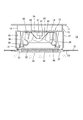
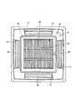
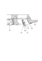
図1は、本発明の実施形態に係る室内空調システムの室内ユニットの側部断面図、図2は、室内ユニットの化粧パネルを室内側から見た平面図である。図3は、室内ユニットのフラップ部分の断面図である。
Embodiments of an indoor air conditioning system according to the present invention will be described below with reference to the drawings.
FIG. 1 is a side sectional view of an indoor unit of an indoor air conditioning system according to an embodiment of the present invention, and FIG. 2 is a plan view of a decorative panel of the indoor unit as viewed from the indoor side. FIG. 3 is a cross-sectional view of the flap portion of the indoor unit.
本実施形態においては、図1に示すように、室内ユニット10は、建屋の天井11とこの天井11の下方に設置された天井板12との間の天井空間13に設置されるものである。
この室内ユニット10は、図1に示すように、下面が開放された箱型に形成された空気調和機本体14を備えており、空気調和機本体14は、吊りボルト15で天井から吊り下げられた状態で設置される。この空気調和機本体14の内側には、発泡スチロール製の断熱部材16が、空気調和機本体14の側板17の内面に接した状態で配置され、側板17における結露を防止している。
In this embodiment, as shown in FIG. 1, the
As shown in FIG. 1, the
空気調和機本体14の上板の下面には、ファンモータ21が取り付けられており、このファンモータ21には、ファンモータ21の駆動により回転駆動される回転シャフト22が下方に延在するように設けられている。この回転シャフト22の下端部分には、遠心ファン23が取り付けられており、このファンモータ21と遠心ファン23とで送風装置20を構成している。
A
遠心ファン23は、環状の板状に形成された主板24を備えている。主板24の中心部分には、下方に延出する逆円錐台形状のモータ収容部25が形成されている。
モータ収容部25には、ファンモータ21が収容されており、ファンモータ21の回転シャフト22は、下方に延在しモータ収容部25の底面に連結されている。そして、ファンモータ21を回転駆動させることにより、回転シャフト22を介して遠心ファン23を回転動作させるように構成されている。
The
A
主板24の下方には、シュラウド26が設けられており、シュラウド26は、周面が弧状に形成された環状に形成されている。主板24とシュラウド26の内周面との間には、周方向に所定間隔をもって配置される複数の翼27が一体に形成されている。
シュラウド26の下方には、オリフィス30が配置されており、オリフィス30は、周面が弧状に形成された環状に形成されている。
A
An
この送風装置20と断熱部材16との間には、送風装置20の側方を取り囲むように、平面視でほぼ四角形状に曲折形成された熱交換器30が配置されている。
熱交換器30は、冷房運転時には、冷媒の蒸発器として機能し、暖房運転時、冷媒の放熱器として機能する熱交換器30である。熱交換器30は、空気調和機本体14の内部に吸い込まれる室内の空気と冷媒との熱交換を行って、冷房運転時には、空調室内の空気を冷却し、暖房運転時には、室内の空気を加熱することができるように構成されている。
Between the
The
また、熱交換器30の下側には、熱交換器30の下面に対応するようにドレンパン31が配置されている。このドレンパン31は、熱交換器30で発生するドレン水を受けるためのものである。また、ドレンパン31の中央部分には、送風装置20の吸い込み口32が形成されている。
Further, a
また、空気調和機本体14の下面には、図1および図2に示すように、空気調和機本体14の下側開口を覆うように、ほぼ四角形状の化粧パネル33が取り付けられている。
化粧パネル33の中央部分には、ドレンパン31の吸い込み口32に連通する吸い込み口34が形成されており、この吸い込み口34部分には、吸い込み口34を覆う吸い込みグリル35が着脱可能に取り付けられている。吸い込みグリル35の空気調和機本体14側には、空気中の塵などを除去するためのフィルタ36が設けられている。
Further, as shown in FIGS. 1 and 2, a substantially rectangular
A
化粧パネル33の吸い込み口34の外側であって化粧パネル33の各辺に沿った位置には、空調後の空気を室内に送る吹出口37がそれぞれ形成されている。そして、ファンモータ21により回転シャフト22を回転駆動させて遠心ファン23を回転させることにより、室内の空気は、吸い込み口32,34から吸い込まれ、フィルタ36を通過した後に熱交換器30を通過して熱交換され、吹出口37から空調後の空気が室内に送られるように構成されている。
また、各吹出口37には、図2および図3に示すように、風向を変更するフラップ38がそれぞれ設けられている。各フラップ38の両端部には、支持軸(図示せず)が設けられており、この支持軸を吹出口37の両端辺に支持させることにより、支持軸を中心として回動自在に形成されている。また、各フラップ38の裏面(空気調和機本体側の面)の長手方向ほぼ中央には、ヒンジ部39が設けられており、このヒンジ部39をフラップ駆動モータ40(図5を参照)を介して駆動することにより、各フラップ38をそれぞれ独立して回動駆動できるように構成されている。
フラップ38は、本実施形態においては、図3に示すように、第1段階(F1)から第5段階(F5)まで5段階で角度調節をすることができるように構成されている。第1段階は、最も角度が小さく、風を横方向に吹き出す位置であり、第5段階は、最も角度が大きく、風をほぼ真下方向に吹き出す位置である。
Each
In the present embodiment, as shown in FIG. 3, the
また、化粧パネル33の角部には、床温センサ41および人感センサ42がそれぞれ取り付けられている。床温センサ41は、室内の床面の温度を検出するものであり、人感センサ42は、室内に人が存在するか否か、または人の位置を検出するものである。
Further, a
また、本実施形態においては、図4に示すように、1つの空調室内の天井部分に複数の室内ユニット10が設置されている。図4においては、2つの室内ユニット10,10が設置された状態を示している。
図4に示すように、本実施形態においては、1つの室内ユニット10に対して1つの人感センサ42を設置しており、1つの人感センサ42により、人感センサ42が搭載された室内ユニット10の下方の所定の領域における人物の有無を検出するものである。
すなわち、本実施形態においては、各室内ユニット10にそれぞれ1つの人感センサ42を設置することにより、各室内ユニット10の下方の領域ごとに人物が存在するか否かを検出することができるように構成されている。
Moreover, in this embodiment, as shown in FIG. 4, the some
As shown in FIG. 4, in the present embodiment, one
That is, in the present embodiment, it is possible to detect whether or not a person exists in each region below each
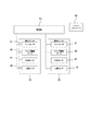
次に、本実施形態における制御構成について説明する。
図5は本実施形態の制御構成を示すブロック図である。図5に示すように、本実施形態においては、例えば、CPUおよびメモリなどからなり所定のプログラムに基づいて動作される制御部45を備えており、制御部45は、制御部45が接続されている複数の室内ユニット10を構成する各機器の動作を制御するように構成されている。
また、各室内ユニット10は、室内の床温度を検出する床温センサ41および室内の人物を検出する人感センサ42をそれぞれ備えている。制御部45は、床温センサ41による室内の床温度および人感センサ42による人物の有無などの検出結果を入力し、各室内ユニット10のファンモータ21およびフラップ駆動モータ32の動作を制御するように構成されている。
Next, the control configuration in the present embodiment will be described.
FIG. 5 is a block diagram showing a control configuration of the present embodiment. As shown in FIG. 5, in the present embodiment, for example, a
Each
また、制御部45は、各室内ユニット10の各人感センサ42の検出結果に応じて、室内の各室内ユニット10に対応する位置に人物が存在するか否かを判断するように構成されている。
ここで、本実施形態においては、制御部45は、室内に存在する人物に送風を当てないようにする風よけ制御および室内の空気を撹拌する温度むら解消制御をそれぞれ行うことができるように構成されている。これら風よけ制御または温度むら解消制御は、リモートコントローラ46の操作により、使用者が任意に選択することができるものである。
The
Here, in the present embodiment, the
制御部45は、風よけ制御を選択している場合に、人感センサ42により人物の存在を検出した場合には、人物に送風が当たらないように、例えば、フラップ38をF1からF3の位置で送風を行うように制御する。
この場合に、本実施形態においては、制御部45は、風よけ制御を選択している場合であっても、人感センサ42により人物が存在しないことを検出した場合には、人感センサ42が搭載された室内ユニット10により温度むら解消制御を行うように構成されている。
例えば、図4に示すように、図において右側に設置された室内ユニット10の人感センサ42により人物の存在を検知し、図において左側に設置された室内ユニット10の人感センサ42により人物の存在を検知しない場合、制御部45は、人物の存在を検出しない室内ユニット10に対して温度むら解消制御を行うようになっている。
When the windshield control is selected and the presence of the person is detected by the
In this case, in the present embodiment, even when the
For example, as shown in FIG. 4, the presence of a person is detected by the
次に、温度むら解消制御について説明する。
図6は温度むら解消制御の動作を示す説明図である。
図6(a)に示すように、温度むら解消制御は、本実施形態においては、フラップ38の回動位置に応じて3つのステップ(第1〜第3のステップ)から構成されている。
Next, temperature unevenness elimination control will be described.
FIG. 6 is an explanatory diagram showing the operation of temperature unevenness elimination control.
As shown in FIG. 6A, the temperature unevenness elimination control is configured of three steps (first to third steps) according to the rotational position of the
第1のステップは、互いに対向する対のフラップ38を第5段階(F5)に位置させるとともに、他の対のフラップ38を第3段階(F3)に位置させて一定時間送風を行う運転である。第2のステップは、すべてのフラップ38を第5段階(F5)に位置させて一定時間送風を行う運転である。第3のステップは、第1のステップで第5段階(F5)に位置させたフラップ38を第3段階(F3)に位置させるとともに、第1のステップで第3段階(F3)に位置させたフラップ38を第5段階(F5)に位置させて一定時間送風を行う運転である。
The first step is an operation in which the pair of
そして、本実施形態においては、制御部45は、第1のステップから順次第2のステップ、第3のステップを行い、第3のステップからは逆に第2のステップ、第1のステップと戻るように制御するものである。すなわち、本実施形態においては、第1のステップと第3のステップとの間に、すべてのフラップ38を第5段階(F5)に位置させる第2のステップを挟んで制御するものである。
In this embodiment, the
本実施形態においては、第1のステップと第3のステップにおいて、第5段階(F5)と第3段階(F3)との組み合わせで送風するようにしているが、これに限定されるものではない。
すなわち、本実施形態においては、第1段階から第5段階のうち、第1段階および第2段階については、室内にいる人に風が当たらない角度で設定されているため、人に風が当たりかつ最も角度が小さい位置として第3段階(F3)を用いたものである。したがって、フラップ38の風向角度が例えば、6段階以上の場合であれば、第4段階と第6段階の組み合わせで行うことも可能であり、4段階であれば、第2段階と第4段階の組み合わせで行うことも可能である。
In the present embodiment, in the first step and the third step, the air is blown in a combination of the fifth stage (F5) and the third stage (F3). However, the present invention is not limited to this. .
That is, in the present embodiment, the first stage and the second stage among the first stage to the fifth stage are set at an angle at which the wind does not hit the person in the room, so the wind hits the person. The third stage (F3) is used as the position having the smallest angle. Therefore, for example, if the wind direction angle of the
また、第1のステップの他の動作としては、例えば、図6(b)に示すように、隣接する対のフラップ38を第5段階(F5)に位置させるとともに、他の対のフラップ38を第3段階(F5)に位置させて一定時間送風を行う運転である。この場合の第3のステップは、第1のステップで第5段階(F5)に位置させたフラップ38を第3段階(F5)に位置させるとともに、第1のステップで第3段階(F5)に位置させたフラップ38を第5段階(F5)に位置させて一定時間送風を行う運転である。
Further, as another operation of the first step, for example, as shown in FIG. 6 (b), the adjacent pair of
なお、温度むら解消制御としては、例えば、第4段階(F4)あるいは第5段階(F5)にフラップ38を位置させることにより、下方に向けて送風を行うようにしてもよいし、第1段階から第5段階までの位置にフラップ38を連続して往復動作させるいわゆるスイング動作をさせるように制御してもよい。
In addition, as temperature unevenness elimination control, for example, the
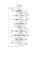
次に、本実施形態の動作について図7および図8に示すフローチャートを参照して説明する。
まず、室内ユニット10により暖房運転を行っている場合の動作について、図7を参照して説明する。
各室内ユニット10が暖房運転を行っている状態で、風よけ制御が選択されている場合には(ST1)、各室内ユニット10の人感センサ42により各室内ユニット10の下方に人物が存在するか否かを検出する(ST2)。いずれかの室内ユニット10の人感センサ42により人物の不在を検出した場合には(ST2:YES)、人物の不在を検出した室内ユニット10の床温センサ41により、室内の床温度を検出する(ST3)。
床温センサ41により、室内の床温度が一定の温度(例えば、18℃)以下であることを検出した場合には(ST3:YES)、制御部45は、温度むら解消制御を開始する(ST4)。
Next, the operation of the present embodiment will be described with reference to the flowcharts shown in FIGS.
First, the operation when the
In the state where each
When the
制御部45は、温度むら解消制御を開始したら、時間の計測を開始する(ST5)。そして、温度むら解消制御を行っている間、人感センサ42により各室内ユニット10の下方に人物が存在するか否かを検出する(ST6)。例えば、室内に人物が入室した場合になど、人感センサ42により、人物を検出した場合には(ST6:YES)、直ちに温度むら解消制御を終了する(ST8)。
When the temperature unevenness elimination control is started, the
制御部45は、温度むら解消制御の開始から10分経過したら(ST7:YES)、温度むら解消制御を終了して、風よけ制御に戻る(ST8)。
その後、圧縮機が停止していわゆるサーモOFF動作に移行したら(ST9:YES)、もとの制御に戻り、人感センサ42による人物の検出を継続して行う。
When 10 minutes have elapsed from the start of temperature unevenness elimination control (ST7: YES),
Thereafter, when the compressor stops and shifts to a so-called thermo OFF operation (ST9: YES), the process returns to the original control, and the
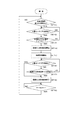
次に、室内ユニット10により冷房運転を行っている場合の動作について、図8を参照して説明する。
各室内ユニット10が冷房運転を行っている状態で、風よけ制御が選択されている場合には(ST11)、各室内ユニット10の人感センサ42により各室内ユニット10の下方に人物が存在するか否かを検出する(ST12)。いずれかの室内ユニット10の人感センサ42により人物の不在を検出した場合には(ST12:YES)、人物の不在を検出した室内ユニット10の床温センサ41により、室内の床温度を検出する(ST13)。
床温センサ41により、室内の床温度が一定の温度(例えば、設定温度+α℃)以上であることを検出した場合には(ST13:YES)、制御部45は、温度むら解消制御を開始する(ST14)。
Next, the operation when the cooling operation is performed by the
In the state where each
When the
制御部45は、温度むら解消制御を開始したら、時間の計測を開始する(ST15)。そして、温度むら解消制御を行っている時に、人感センサ42により、人物を検出した場合には(ST16:YES)、直ちに温度むら解消制御を終了する(ST18)。
When the temperature unevenness elimination control is started, the
制御部45は、温度むら解消制御の開始から、例えば、10分経過したら(ST17)、温度むら解消制御を終了して、風よけ制御に戻る(ST18)。
その後、圧縮機が停止していわゆるサーモOFF動作に移行したら(ST19:YES)、もとの制御に戻り、人感センサ42による人物の検出を継続して行う。
For example, when 10 minutes have elapsed since the start of the temperature unevenness elimination control (ST17), the
Thereafter, when the compressor stops and shifts to a so-called thermo OFF operation (ST19: YES), the process returns to the original control, and the
なお、本実施形態においては、温度むら解消制御を一定時間経過後に終了するように制御するものであるが、例えば、床温センサ41により床温度を検出し、床温度が一定温度に達したら、温度むら解消制御を終了するようにしてもよい。
また、本実施形態においては、人感センサ42により、人物が不在であることを検出した場合に、当該室内ユニット10の温度むら解消制御を行うようにしているが、当該室内ユニット10と隣接配置された室内ユニット10との設置間隔によっては、当該室内ユニット10により人物の不在を検出して温度むら解消制御を行った場合に、隣接配置された室内ユニット10の下方に存在する人物に送風が当たってしまうおそれがある。
そのため、隣接配置された室内ユニット10側のフラップ38は、風よけ制御のまま継続し、その他の吹出し口のフラップ38のみを温度むら解消制御するようにしてもよい。
In the present embodiment, the temperature unevenness elimination control is controlled to end after a lapse of a certain time. For example, when the floor temperature is detected by the
Further, in the present embodiment, when the
Therefore, the
以上述べたように、本実施形態においては、制御部45により、風よけ制御が選択されている状態で、いずれかの室内ユニット10の人感センサ42により人物の不在を検出した場合に、当該室内ユニット10の温度むら解消制御を行うようにしているので、人物に対して送風が当たってしまうことを防止するとともに、室内の温度むらを解消することが可能となる。
また、制御部45により、人物の不在を検出した場合であって、床温センサ41により室内の床温度が、暖房運転時では一定温度より低い場合、冷房運転時では一定温度より高い場合に、当該室内ユニット10の温度むら解消制御を行うようにしているので、設定温度に対して一定の温度差が発生している場合に、温度むら解消制御を行うことにより、効率よく室内空気の温度むらを解消することができる。
As described above, in the present embodiment, when the absence of a person is detected by the
Further, when the
さらに、制御部45により、温度むら解消制御の開始から一定時間経過したら、温度むら解消制御を終了するようにしているので、不必要に温度むら解消制御を行わなくて済む。また、制御部45により、温度むら解消制御を行っている間に、人感センサ42により人物の存在を検出した場合には、温度むら解消制御することにより、人物に対して送風が当たってしまうことを防止することができる。
Furthermore, since the
なお、本発明の実施形態について図面に基づいて説明したが、本発明は、前記実施形態に限られるものではなく、発明の要旨を逸脱しない範囲で変更可能である。 Although the embodiments of the present invention have been described with reference to the drawings, the present invention is not limited to the above-described embodiments and can be modified without departing from the scope of the invention.
10 室内ユニット
14 空気調和機本体
20 送風装置
21 ファンモータ
23 遠心ファン
30 熱交換器
33 化粧パネル
37 吹出口
38 フラップ
40 フラップ駆動モータ
41 床温センサ
42 人感センサ
45 制御部
DESCRIPTION OF
Claims (5)
前記複数の室内ユニットは、下面の周縁部に沿うように複数の吹出口が形成された空気調和機と、前記吹出口に回動可能に設けられそれぞれ独立して上下方向の風向角度を変更することが可能な複数のフラップと、前記室内ユニットの下方における人物の有無を検出する人感センサとを備え、
前記制御部は、風よけ制御および温度むら解消制御を行うものであり、前記制御部は、前記風よけ制御が選択されている状態で、いずれかの前記室内ユニットの前記人感センサにより人物の不在を検出した場合に、当該室内ユニットの温度むら解消制御を行うことを特徴とする室内空調システム。 A plurality of indoor units provided on the ceiling of the air conditioning room, and a controller that controls the plurality of indoor units,
The plurality of indoor units is provided with an air conditioner having a plurality of air outlets formed along the peripheral edge of the lower surface, and is rotatably provided at the air outlet, and independently changes the airflow direction angle in the vertical direction. A plurality of flaps capable of being, and a human sensor for detecting the presence or absence of a person below the indoor unit,
The control unit performs windshield control and temperature unevenness elimination control, and the control unit is controlled by the human sensor of any of the indoor units in a state where the windshield control is selected. An indoor air conditioning system that performs temperature unevenness elimination control of the indoor unit when the absence of a person is detected.
前記制御部は、人物の不在を検出した場合で、かつ、前記床温センサにより室内の床温度が、暖房運転時では一定温度より低い場合、冷房運転時では一定温度より高い場合に、当該室内ユニットの前記温度むら解消制御を行うことを特徴とする請求項1に記載の室内空調システム。 The indoor unit further includes a bed temperature sensor for detecting a floor temperature in the room,
When the control unit detects the absence of a person, and the floor temperature sensor detects that the indoor floor temperature is lower than a certain temperature during heating operation, or higher than a certain temperature during cooling operation, The indoor air conditioning system according to claim 1, wherein the temperature unevenness elimination control of the unit is performed.
Priority Applications (4)
| Application Number | Priority Date | Filing Date | Title |
|---|---|---|---|
| JP2015102565A JP6767688B2 (en) | 2015-05-20 | 2015-05-20 | Indoor air conditioning system |
| US15/140,071 US10288303B2 (en) | 2015-05-20 | 2016-04-27 | Room air conditioning system |
| EP16170097.6A EP3096088B1 (en) | 2015-05-20 | 2016-05-18 | Room air conditioning system |
| CN201610808738.XA CN106322532B (en) | 2015-05-20 | 2016-05-20 | Indoor air conditioning system |
Applications Claiming Priority (1)
| Application Number | Priority Date | Filing Date | Title |
|---|---|---|---|
| JP2015102565A JP6767688B2 (en) | 2015-05-20 | 2015-05-20 | Indoor air conditioning system |
Related Child Applications (1)
| Application Number | Title | Priority Date | Filing Date |
|---|---|---|---|
| JP2015233115A Division JP2016217693A (en) | 2015-11-30 | 2015-11-30 | Recessed ceiling indoor unit |
Publications (2)
| Publication Number | Publication Date |
|---|---|
| JP2016217618A true JP2016217618A (en) | 2016-12-22 |
| JP6767688B2 JP6767688B2 (en) | 2020-10-14 |
Family
ID=56014894
Family Applications (1)
| Application Number | Title | Priority Date | Filing Date |
|---|---|---|---|
| JP2015102565A Active JP6767688B2 (en) | 2015-05-20 | 2015-05-20 | Indoor air conditioning system |
Country Status (4)
| Country | Link |
|---|---|
| US (1) | US10288303B2 (en) |
| EP (1) | EP3096088B1 (en) |
| JP (1) | JP6767688B2 (en) |
| CN (1) | CN106322532B (en) |
Cited By (3)
| Publication number | Priority date | Publication date | Assignee | Title |
|---|---|---|---|---|
| KR20190137408A (en) * | 2018-06-01 | 2019-12-11 | 엘지전자 주식회사 | A ceiling type air conditioner and controlling method thereof |
| JP2020125881A (en) * | 2019-02-06 | 2020-08-20 | 三菱電機株式会社 | Air conditioning system and control method for air conditioning system |
| JP2022157186A (en) * | 2021-03-31 | 2022-10-14 | ダイキン工業株式会社 | Air conditioning control device, and air conditioning system |
Families Citing this family (23)
| Publication number | Priority date | Publication date | Assignee | Title |
|---|---|---|---|---|
| CN106885351A (en) * | 2017-04-20 | 2017-06-23 | 广东高村空调制造有限公司 | A kind of central air-conditioning automation control system |
| JPWO2018229923A1 (en) * | 2017-06-15 | 2019-12-26 | 三菱電機株式会社 | Air conditioner indoor unit |
| CN114893887B (en) * | 2017-07-14 | 2024-09-13 | 大金工业株式会社 | Sound information analysis system, air conditioner, information processing device, communication system, equipment control system, and equipment management system |
| US11391470B2 (en) | 2017-08-25 | 2022-07-19 | Gd Midea Heating & Ventilating Equipment Co., Ltd. | Temperature-sensing bulb support for air-conditioner indoor unit, and air-conditioner indoor unit |
| EP3686506B1 (en) * | 2017-09-20 | 2025-05-07 | LG Electronics Inc. | Ceiling-type indoor unit of air conditioner |
| CN108302695B (en) * | 2018-01-03 | 2020-05-05 | 广东美的制冷设备有限公司 | Human body detection method, human body detection equipment and air conditioner |
| CN108302729B (en) * | 2018-01-03 | 2020-06-05 | 广东美的制冷设备有限公司 | Human body detection method, human body detection equipment and air conditioner |
| JP7049167B2 (en) * | 2018-04-20 | 2022-04-06 | 三菱重工サーマルシステムズ株式会社 | Air conditioner |
| CN108758802A (en) * | 2018-04-26 | 2018-11-06 | 广东美的制冷设备有限公司 | Air conditioner and its control method, device |
| KR102168705B1 (en) * | 2018-05-15 | 2020-10-22 | 엘지전자 주식회사 | Method for controlling a ceiling type air conditioner |
| KR102639774B1 (en) * | 2018-12-18 | 2024-02-21 | 엘지전자 주식회사 | Ceiling type indoor unit of air conditioner |
| WO2020170289A1 (en) * | 2019-02-18 | 2020-08-27 | 三菱電機株式会社 | Air-conditioning device |
| CN110108007B (en) * | 2019-05-16 | 2020-03-06 | 珠海格力电器股份有限公司 | Method and device for determining wind sweeping range of wind outlet equipment and air conditioner |
| US12130042B2 (en) | 2019-05-30 | 2024-10-29 | Mitsubishi Electric Corporation | Indoor unit of air-conditioning apparatus |
| CN110274364A (en) * | 2019-06-28 | 2019-09-24 | 宁波奥克斯电气股份有限公司 | A kind of control method, system and the air-conditioning of air conditioner intelligent air-supply |
| WO2021040634A1 (en) * | 2019-08-26 | 2021-03-04 | Ozyegin Universitesi | An adaptive vent system for providing localized and customized thermal comfort. |
| CN112361550B (en) * | 2020-10-29 | 2021-09-21 | 珠海格力电器股份有限公司 | Air conditioner anti-direct-blowing control method and device and air conditioner |
| JP7252480B2 (en) * | 2021-01-29 | 2023-04-05 | ダイキン工業株式会社 | blower |
| CN113819529A (en) * | 2021-08-31 | 2021-12-21 | 青岛海尔空调器有限总公司 | Cabinet air conditioner air outlet control method and device and cabinet air conditioner |
| KR20230050101A (en) * | 2021-10-07 | 2023-04-14 | 엘지전자 주식회사 | Air conditioner |
| CN113932369A (en) * | 2021-11-25 | 2022-01-14 | 宁波奥克斯电气股份有限公司 | Control method and device of air conditioner, air conditioner and storage medium |
| CN114838484B (en) * | 2022-04-24 | 2024-01-23 | 美的集团武汉暖通设备有限公司 | Air conditioner control method, air conditioner and computer readable storage medium |
| CN115899837B (en) * | 2022-12-01 | 2024-07-16 | 珠海格力电器股份有限公司 | Control method and device of patio type air conditioner and patio type air conditioner |
Citations (5)
| Publication number | Priority date | Publication date | Assignee | Title |
|---|---|---|---|---|
| JP2004150731A (en) * | 2002-10-31 | 2004-05-27 | Daikin Ind Ltd | Air conditioner |
| JP2011069591A (en) * | 2009-09-28 | 2011-04-07 | Daikin Industries Ltd | Control device |
| WO2011093343A1 (en) * | 2010-01-26 | 2011-08-04 | ダイキン工業株式会社 | Ceiling-mounted indoor unit for air conditioning device |
| JP2011185591A (en) * | 2010-02-15 | 2011-09-22 | Daikin Industries Ltd | Indoor unit of air conditioning device |
| JP2015021719A (en) * | 2013-07-24 | 2015-02-02 | 日立アプライアンス株式会社 | Air conditioner |
Family Cites Families (16)
| Publication number | Priority date | Publication date | Assignee | Title |
|---|---|---|---|---|
| DK161152C (en) | 1983-03-03 | 1991-11-11 | Genentech Inc | POLYPEPTIDE OF PROPERTIES AS HUMAN BETA-NERVE GROWTH FACTOR AND METHOD FOR PREPARATION THEREOF, DNA ISOLAT comprising a sequence encoding the polypeptide is replicable expression vector for DNA SEQUENCE recombinant host cell transformed with the vector, pharmaceutical composition comprising the polypeptide and be stated in. THAT INCLUDES THE APPLICATION OF THE POLYPEPTID IN FORCE. OF A PHARMACEUTICAL PREPARATION |
| JP4311212B2 (en) * | 2004-01-26 | 2009-08-12 | ダイキン工業株式会社 | Ceiling-embedded air conditioner and control method thereof |
| KR100640801B1 (en) * | 2005-05-10 | 2006-11-02 | 엘지전자 주식회사 | Vane Control Method of Ceiling Air Conditioner |
| JP4537903B2 (en) | 2005-07-25 | 2010-09-08 | 三菱電機株式会社 | Air conditioner |
| KR101584801B1 (en) * | 2008-12-23 | 2016-01-12 | 엘지전자 주식회사 | Air conditioner and method for controlling the same |
| CN201488140U (en) * | 2009-08-22 | 2010-05-26 | 海尔集团公司 | An IFP air conditioner |
| EP2484986B1 (en) * | 2009-09-28 | 2020-08-05 | Daikin Industries, Ltd. | Control device |
| JP2011196666A (en) | 2010-03-24 | 2011-10-06 | Daikin Industries Ltd | Air conditioner |
| JP2011099609A (en) | 2009-11-05 | 2011-05-19 | Daikin Industries Ltd | Indoor unit of air conditioner |
| JP5310792B2 (en) | 2010-01-26 | 2013-10-09 | ダイキン工業株式会社 | Air conditioner ceiling-mounted indoor unit |
| CN102759173B (en) * | 2011-04-26 | 2014-09-03 | 珠海格力电器股份有限公司 | Method for controlling operation mode of air conditioner and air conditioner |
| JP2013224755A (en) | 2012-04-20 | 2013-10-31 | Corona Corp | Air conditioner |
| JP5967358B2 (en) * | 2012-04-27 | 2016-08-10 | 株式会社富士通ゼネラル | Control circuit and control program for air conditioner |
| JP5932998B2 (en) * | 2012-06-22 | 2016-06-08 | 三菱電機株式会社 | Air conditioning system |
| CN103912960B (en) * | 2013-01-07 | 2017-08-01 | 苏州三星电子有限公司 | A kind of air-conditioner control system and its control method |
| JP6631826B2 (en) | 2015-01-28 | 2020-01-15 | パナソニックIpマネジメント株式会社 | Recessed ceiling indoor unit |
-
2015
- 2015-05-20 JP JP2015102565A patent/JP6767688B2/en active Active
-
2016
- 2016-04-27 US US15/140,071 patent/US10288303B2/en active Active
- 2016-05-18 EP EP16170097.6A patent/EP3096088B1/en active Active
- 2016-05-20 CN CN201610808738.XA patent/CN106322532B/en active Active
Patent Citations (5)
| Publication number | Priority date | Publication date | Assignee | Title |
|---|---|---|---|---|
| JP2004150731A (en) * | 2002-10-31 | 2004-05-27 | Daikin Ind Ltd | Air conditioner |
| JP2011069591A (en) * | 2009-09-28 | 2011-04-07 | Daikin Industries Ltd | Control device |
| WO2011093343A1 (en) * | 2010-01-26 | 2011-08-04 | ダイキン工業株式会社 | Ceiling-mounted indoor unit for air conditioning device |
| JP2011185591A (en) * | 2010-02-15 | 2011-09-22 | Daikin Industries Ltd | Indoor unit of air conditioning device |
| JP2015021719A (en) * | 2013-07-24 | 2015-02-02 | 日立アプライアンス株式会社 | Air conditioner |
Cited By (7)
| Publication number | Priority date | Publication date | Assignee | Title |
|---|---|---|---|---|
| KR20190137408A (en) * | 2018-06-01 | 2019-12-11 | 엘지전자 주식회사 | A ceiling type air conditioner and controlling method thereof |
| KR102167891B1 (en) * | 2018-06-01 | 2020-10-20 | 엘지전자 주식회사 | A ceiling type air conditioner and controlling method thereof |
| US11280516B2 (en) | 2018-06-01 | 2022-03-22 | Lg Electronics Inc. | Ceiling type air conditioner and controlling method thereof |
| JP2020125881A (en) * | 2019-02-06 | 2020-08-20 | 三菱電機株式会社 | Air conditioning system and control method for air conditioning system |
| JP7329332B2 (en) | 2019-02-06 | 2023-08-18 | 三菱電機株式会社 | AIR CONDITIONING SYSTEM AND CONTROL METHOD OF AIR CONDITIONING SYSTEM |
| JP2022157186A (en) * | 2021-03-31 | 2022-10-14 | ダイキン工業株式会社 | Air conditioning control device, and air conditioning system |
| JP7303449B2 (en) | 2021-03-31 | 2023-07-05 | ダイキン工業株式会社 | Air conditioning control device and air conditioning system |
Also Published As
| Publication number | Publication date |
|---|---|
| US10288303B2 (en) | 2019-05-14 |
| EP3096088B1 (en) | 2021-09-22 |
| EP3096088A1 (en) | 2016-11-23 |
| US20160341438A1 (en) | 2016-11-24 |
| CN106322532B (en) | 2021-01-19 |
| JP6767688B2 (en) | 2020-10-14 |
| CN106322532A (en) | 2017-01-11 |
Similar Documents
| Publication | Publication Date | Title |
|---|---|---|
| JP6767688B2 (en) | Indoor air conditioning system | |
| JP6932009B2 (en) | Indoor unit of air conditioner | |
| US20120288363A1 (en) | Ceiling-mounted indoor unit for air conditioning apparatus | |
| JP5987882B2 (en) | Indoor unit of air conditioner | |
| JP6498598B2 (en) | Control device, air conditioning system including the same, and control method | |
| JP6071626B2 (en) | Indoor unit and air conditioner | |
| JP6734624B2 (en) | Indoor unit of air conditioner | |
| CN108474581B (en) | Air Conditioning System | |
| WO2004040204A1 (en) | Indoor apparatus for air conditioner | |
| JP2005207705A (en) | Ceiling-embedded air conditioner and control method thereof | |
| JP6808999B2 (en) | Air conditioner | |
| JP2004150731A (en) | Air conditioner | |
| JP6631826B2 (en) | Recessed ceiling indoor unit | |
| CN109923351B (en) | Indoor unit of air conditioner | |
| JP7163662B2 (en) | Environmental control system and air conditioner | |
| JP5963048B2 (en) | Air conditioner | |
| JP7206684B2 (en) | Environmental control system and air conditioner | |
| JP6631832B2 (en) | Recessed ceiling indoor unit | |
| JP2014092287A (en) | Air conditioning apparatus and control method of the same | |
| JP6418147B2 (en) | air conditioner | |
| KR20180085127A (en) | Air-conditioner | |
| JP6823493B2 (en) | Indoor unit of air conditioner | |
| KR102336631B1 (en) | Air-conditioner | |
| JP2016217693A (en) | Recessed ceiling indoor unit | |
| JP6592884B2 (en) | Indoor unit of air conditioner |
Legal Events
| Date | Code | Title | Description |
|---|---|---|---|
| A621 | Written request for application examination |
Free format text: JAPANESE INTERMEDIATE CODE: A621 Effective date: 20180517 |
|
| A977 | Report on retrieval |
Free format text: JAPANESE INTERMEDIATE CODE: A971007 Effective date: 20190220 |
|
| A131 | Notification of reasons for refusal |
Free format text: JAPANESE INTERMEDIATE CODE: A131 Effective date: 20190226 |
|
| A521 | Request for written amendment filed |
Free format text: JAPANESE INTERMEDIATE CODE: A523 Effective date: 20190423 |
|
| A131 | Notification of reasons for refusal |
Free format text: JAPANESE INTERMEDIATE CODE: A131 Effective date: 20190910 |
|
| A521 | Request for written amendment filed |
Free format text: JAPANESE INTERMEDIATE CODE: A523 Effective date: 20191108 |
|
| A131 | Notification of reasons for refusal |
Free format text: JAPANESE INTERMEDIATE CODE: A131 Effective date: 20200225 |
|
| A521 | Request for written amendment filed |
Free format text: JAPANESE INTERMEDIATE CODE: A523 Effective date: 20200410 |
|
| TRDD | Decision of grant or rejection written | ||
| A01 | Written decision to grant a patent or to grant a registration (utility model) |
Free format text: JAPANESE INTERMEDIATE CODE: A01 Effective date: 20200804 |
|
| A61 | First payment of annual fees (during grant procedure) |
Free format text: JAPANESE INTERMEDIATE CODE: A61 Effective date: 20200902 |
|
| R151 | Written notification of patent or utility model registration |
Ref document number: 6767688 Country of ref document: JP Free format text: JAPANESE INTERMEDIATE CODE: R151 |