JP2016217536A - Solenoid valve for low temperature high pressure steam for spacecraft launch device - Google Patents
Solenoid valve for low temperature high pressure steam for spacecraft launch device Download PDFInfo
- Publication number
- JP2016217536A JP2016217536A JP2016099903A JP2016099903A JP2016217536A JP 2016217536 A JP2016217536 A JP 2016217536A JP 2016099903 A JP2016099903 A JP 2016099903A JP 2016099903 A JP2016099903 A JP 2016099903A JP 2016217536 A JP2016217536 A JP 2016217536A
- Authority
- JP
- Japan
- Prior art keywords
- plunger
- valve
- stopper
- passage
- stoppers
- Prior art date
- Legal status (The legal status is an assumption and is not a legal conclusion. Google has not performed a legal analysis and makes no representation as to the accuracy of the status listed.)
- Granted
Links
Images


Classifications
-
- F—MECHANICAL ENGINEERING; LIGHTING; HEATING; WEAPONS; BLASTING
- F16—ENGINEERING ELEMENTS AND UNITS; GENERAL MEASURES FOR PRODUCING AND MAINTAINING EFFECTIVE FUNCTIONING OF MACHINES OR INSTALLATIONS; THERMAL INSULATION IN GENERAL
- F16K—VALVES; TAPS; COCKS; ACTUATING-FLOATS; DEVICES FOR VENTING OR AERATING
- F16K31/00—Actuating devices; Operating means; Releasing devices
- F16K31/02—Actuating devices; Operating means; Releasing devices electric; magnetic
- F16K31/06—Actuating devices; Operating means; Releasing devices electric; magnetic using a magnet, e.g. diaphragm valves, cutting off by means of a liquid
- F16K31/0603—Multiple-way valves
- F16K31/062—Multiple-way valves the valve element being at least partially ball-shaped
-
- F—MECHANICAL ENGINEERING; LIGHTING; HEATING; WEAPONS; BLASTING
- F16—ENGINEERING ELEMENTS AND UNITS; GENERAL MEASURES FOR PRODUCING AND MAINTAINING EFFECTIVE FUNCTIONING OF MACHINES OR INSTALLATIONS; THERMAL INSULATION IN GENERAL
- F16K—VALVES; TAPS; COCKS; ACTUATING-FLOATS; DEVICES FOR VENTING OR AERATING
- F16K31/00—Actuating devices; Operating means; Releasing devices
- F16K31/02—Actuating devices; Operating means; Releasing devices electric; magnetic
- F16K31/06—Actuating devices; Operating means; Releasing devices electric; magnetic using a magnet, e.g. diaphragm valves, cutting off by means of a liquid
- F16K31/0603—Multiple-way valves
- F16K31/0624—Lift valves
- F16K31/0634—Lift valves with fixed seats positioned between movable valve members
- F16K31/0637—Lift valves with fixed seats positioned between movable valve members with ball shaped valve members
Landscapes
- Engineering & Computer Science (AREA)
- General Engineering & Computer Science (AREA)
- Mechanical Engineering (AREA)
- Magnetically Actuated Valves (AREA)
- Multiple-Way Valves (AREA)
- Chemical & Material Sciences (AREA)
- Combustion & Propulsion (AREA)
- Remote Sensing (AREA)
- Aviation & Aerospace Engineering (AREA)
Abstract
Description
本発明は、電磁弁の分野に関する。より詳細には、本発明は、宇宙機に推進剤などの低温流体を供給するための、球状体を含む電磁弁に関する。本発明はまた、電磁弁によって制御される分配弁を提供する。 The present invention relates to the field of solenoid valves. More specifically, the present invention relates to a solenoid valve including a spherical body for supplying a cryogenic fluid such as a propellant to a spacecraft. The present invention also provides a dispensing valve controlled by a solenoid valve.
ロケットは、燃料及び酸化剤によって推進される。燃料は、一般的には推進剤であり、タンク内に貯蔵され、その後、スラスタに正確に供給されるように低温条件下で分配される。タンクには、ソレノイド弁が接続されている。ソレノイド弁は通常、ロケットの電気回路網の電流を利用する電磁アクチュエータを有しているが、電磁アクチュエータは、電気回路網で利用可能なアンペア数に適合したものでなければならない。 The rocket is propelled by fuel and oxidant. The fuel is typically a propellant, stored in a tank, and then distributed under low temperature conditions to be accurately fed to the thruster. A solenoid valve is connected to the tank. Solenoid valves typically have an electromagnetic actuator that utilizes the current of the rocket's electrical network, but the electromagnetic actuator must be compatible with the amperage available in the electrical network.
電磁弁を開に維持するためには、電磁弁のコイルに電流を連続的に供給する必要がある。しかし、コイルに電流が流れると電磁弁の温度が上昇し、場合によっては100℃にまでなり、燃料の発火を招くおそれがある。 In order to keep the solenoid valve open, it is necessary to continuously supply current to the coil of the solenoid valve. However, when a current flows through the coil, the temperature of the solenoid valve rises and in some cases reaches 100 ° C., which may cause fuel ignition.
燃料及び推進剤は、ガス状で、かつ−200℃に達する温度及び約400barの圧力で循環する。この圧力は、テイクオフ中のロケットの機械振動と同様に、シール要素に破壊的な力を及ぼす。これらの振動は60gの加速度に変換でき、これは、閉動作の衝撃とともに、シール面の摩耗を速める。 The fuel and propellant are gaseous and circulate at a temperature reaching -200 ° C and a pressure of about 400 bar. This pressure exerts a destructive force on the sealing element, similar to the mechanical vibration of the rocket during take-off. These vibrations can be converted to 60 g of acceleration, which, along with the impact of the closing action, accelerates the wear of the sealing surface.
特許文献1(フランス国特許出願公開第2487942 A1号明細書)には、分配部と、該分配部を制御する調整部とを含む三方弁が開示されている。分配部は、2つの対向配置された弁座と協働する2つの球状体を含む。両球状体間にはシャフトが配置されており、それによって2つの球状体に選択的に開/閉位置をとらせることができ、ベローズを含むピストンによって一方の球状体を駆動することができる。ピストンは調整部によって制御されるが、調整部も、同様にシャフトによって互いに結合されかつばねによって閉位置に保持される2つの球状体を含む。タペットプランジャを含む電磁アクチュエータによって一方の球状体が押され、それによって今度はシャフトを介して他方の球状体が押される。 Patent Document 1 (French Patent Application Publication No. 2487942 A1 specification) discloses a three-way valve including a distribution unit and an adjustment unit that controls the distribution unit. The dispensing part includes two spheres that cooperate with two opposed valve seats. A shaft is disposed between the two spheres, whereby the two spheres can be selectively placed in the open / closed position, and one sphere can be driven by a piston including a bellows. The piston is controlled by the adjusting part, which also comprises two spheres that are connected to each other by a shaft and held in a closed position by a spring. One spherical body is pushed by an electromagnetic actuator including a tappet plunger, which in turn pushes the other spherical body through the shaft.
この構成は、コンパクトではない。加えて、プランジャの球状体と協働する球状体はかなり大きな力を受けるので、球状体の弁座が劣化し、したがってシールは使用に伴って損なわれる。実際に、閉動作は、電磁弁のプランジャの運動エネルギーを弁座が吸収することを意味する。同時に、球状体を弁座に押し付けるための力を受けて、プランジャのタペットは次第に加工硬化を起こす。その結果として、球状体を弁座に向けて正確に変位させたり効果的に中央配置したりすることを保証することは不可能であり、したがってシールはやはり劣化する。したがって、球状体を含む弁であって、対応するオリフィスを介して球状体がその弁座から押されるように構成された弁を提供することができれば有用であろう。 This configuration is not compact. In addition, the spherical body that cooperates with the spherical body of the plunger is subjected to a considerable force, so that the valve seat of the spherical body is deteriorated and therefore the seal is damaged with use. Actually, the closing operation means that the valve seat absorbs the kinetic energy of the plunger of the solenoid valve. At the same time, the plunger tappet gradually undergoes work hardening under the force of pressing the spherical body against the valve seat. As a result, it is not possible to ensure that the sphere is accurately displaced or effectively centered towards the valve seat, and therefore the seal is also degraded. Therefore, it would be useful to provide a valve that includes a sphere that is configured such that the sphere is pushed from its seat through the corresponding orifice.
本発明の目的は、先行技術に伴う諸問題のうちの少なくとも1つを解決することである。より正確には、本発明の1つの目的は、球状体を含む電磁弁の寿命を延ばすことである。本発明の別の目的は、電磁弁のコンパクトさを改善することである。 The object of the present invention is to solve at least one of the problems associated with the prior art. More precisely, one object of the present invention is to extend the life of solenoid valves that contain spherical bodies. Another object of the present invention is to improve the compactness of the solenoid valve.
本発明は、電磁弁、特に低温流体用の電磁弁であって、互いに逆方向に向けて配置された2つの弁座と、2つの弁座を互いに連通させる通路と、各々が2つの弁座の一方と協働して該弁座の開閉を可能ならしめる2つのストッパと、一方のストッパから他方のストッパへ開閉運動を伝えるようにストッパに接触して変位可能なタペットと、例えば磁気源から生じた磁束を伝達する磁気回路とを含む弁に関する。タペットに磁気材料を含めること及び磁気回路内に可変エアギャップを画定することにより、タペットを磁束により駆動できるようにし、それによって各ストッパをそれぞれの弁座に対して変位させることができるようにした点において、この弁は注目に値する。 The present invention relates to an electromagnetic valve, in particular, an electromagnetic valve for a cryogenic fluid, wherein two valve seats arranged in opposite directions to each other, a passage communicating the two valve seats with each other, and two valve seats each Two stoppers that enable opening and closing of the valve seat in cooperation with one of the two, a tappet that can be displaced in contact with the stopper so as to transmit the opening and closing movement from one stopper to the other stopper, for example, from a magnetic source And a magnetic circuit for transmitting the generated magnetic flux. By including magnetic material in the tappet and defining a variable air gap in the magnetic circuit, the tappet can be driven by magnetic flux, thereby allowing each stopper to be displaced relative to its respective valve seat. In terms, this valve is noteworthy.
本発明の有利な実施形態によれば、タペットは、ストッパ間、できれば弁座間に配置される。 According to an advantageous embodiment of the invention, the tappet is arranged between the stoppers, preferably between the valve seats.
本発明は、電磁弁、特に低温流体用の電磁弁であって、互いに逆方向に向けて配置された2つの弁座と、各々が2つの弁座の一方と協働して該弁座の開閉を可能ならしめる2つのストッパと、2つの弁座を互いに連通させる通路と、磁場源によって駆動させることができかつ2つのストッパをそれぞれの弁座に対して変位させる磁性プランジャを含む磁気回路とを含む弁にも関する。この弁は、プランジャがストッパ間に配置されており、プランジャを2つの弁座の一方から遠ざけることによって、当該一方の弁座が対応するストッパによって閉じられるようにした点において注目に値する。 The present invention relates to a solenoid valve, particularly a solenoid valve for a cryogenic fluid, and two valve seats arranged in opposite directions to each other, each of which cooperates with one of the two valve seats. A magnetic circuit including two stoppers for enabling opening and closing, a passage for communicating the two valve seats with each other, and a magnetic plunger that can be driven by a magnetic field source and that displaces the two stoppers with respect to the respective valve seats; It also relates to valves including This valve is notable in that the plunger is arranged between the stoppers, and by moving the plunger away from one of the two valve seats, the one valve seat is closed by the corresponding stopper.
本発明の有利な実施形態によれば、弁は、2つのストッパとそれぞれ協働するタペットを含み、各タペットは、対応する弁座を通ることによってストッパをそれぞれ変位させることができる。 According to an advantageous embodiment of the invention, the valve comprises a tappet cooperating with two stoppers, each tappet being able to respectively displace the stopper by passing through a corresponding valve seat.
本発明の有利な実施形態によれば、少なくとも一方または両方のタペットは、プランジャ内に後退可能であるようにプランジャに対して変位自在に取り付けられている。プランジャは、少なくとも1つまたは2つのばねを含み、該ばねによってタペットがプランジャ外に押し出されるように構成されていることが好ましい。 According to an advantageous embodiment of the invention, at least one or both tappets are displaceably mounted relative to the plunger so that they can be retracted into the plunger. The plunger preferably includes at least one or two springs configured to push the tappet out of the plunger.
本発明の有利な実施形態によれば、少なくとも一方または両方のタペットは、ストッパの一方と協働する相対的に肉薄の部分を含む。 According to an advantageous embodiment of the invention, at least one or both tappets comprise a relatively thin part cooperating with one of the stoppers.
本発明の有利な実施形態によれば、プランジャは、通路内の2つの弁座を互いに連通させるように構成された貫通ダクトを含む。 According to an advantageous embodiment of the invention, the plunger includes a through duct configured to communicate two valve seats in the passage with each other.
本発明の有利な実施形態によれば、弁は、プランジャの片側に配置された少なくとも1つのプランジャガイドを含み、好適にはプランジャの両側に各々が配置された2つのプランジャガイドを含む。 According to an advantageous embodiment of the invention, the valve comprises at least one plunger guide arranged on one side of the plunger, preferably two plunger guides each arranged on both sides of the plunger.
本発明の有利な実施形態によれば、少なくとも一方または両方の弁座がプランジャガイドに形成されており、かつ少なくとも一方または両方のプランジャガイドは耐磁性材料でできている。 According to an advantageous embodiment of the invention, at least one or both valve seats are formed in the plunger guide, and at least one or both plunger guides are made of a magnetically resistant material.
本発明の有利な実施形態によれば、弁は、少なくとも1つまたは2つのストッパキャリアを含み、ストッパを開または閉とする間、各ストッパキャリアが、それぞれのストッパを対応する弁座に対して中央に配置させるように構成されている。 According to an advantageous embodiment of the invention, the valve comprises at least one or two stopper carriers, each stopper carrier being against the corresponding valve seat while the stopper is opened or closed. It is configured to be arranged in the center.
本発明の有利な実施形態によれば、弁は、コイルなどの磁場源を含み、弁座の一方は磁場源の内部に配置されており、できれば磁場源を通路が通っている。 According to an advantageous embodiment of the invention, the valve comprises a magnetic field source, such as a coil, one of the valve seats being arranged inside the magnetic field source, preferably with a passage through the magnetic field source.
本発明の有利な実施形態によれば、弁は、2つのストッパのうちの一方(入口側ストッパと呼ぶ)が閉でありかつ2つのストッパのうちの他方(出口側ストッパと呼ぶ)が開であるような閉位置にプランジャを保持するプランジャばねを含む。 According to an advantageous embodiment of the invention, the valve is closed when one of the two stoppers (referred to as the inlet stopper) is closed and the other of the two stoppers (referred to as the outlet stopper) is open. A plunger spring is included that holds the plunger in a closed position.
本発明の有利な実施形態によれば、弁は、少なくとも1つの、好適には2つのストッパばねを含み、各ストッパばねは、対応するストッパをそれぞれ対応する弁座に接触させて閉位置に保持するように構成されている。 According to an advantageous embodiment of the invention, the valve comprises at least one, preferably two stopper springs, each stopper spring being held in a closed position with the corresponding stopper contacting the corresponding valve seat. Is configured to do.
本発明の有利な実施形態によれば、通路は、入口部分及び出口部分を有する側面部を含み、プランジャは端面を含み、該端面は、プランジャが通路の上記側面部に向けて変位されているときまたは接触したときに入口部分及び出口部分を互いに連通させるように構成されている。 According to an advantageous embodiment of the invention, the passage comprises a side part having an inlet part and an outlet part, the plunger comprises an end face, the end face being displaced towards said side part of the passage. The inlet portion and the outlet portion are configured to communicate with each other when or when they come into contact.
本発明の有利な実施形態によれば、通路は、第3の開口などの開口を含み、開口は、通路によって互いに連通されている2つの弁座から離間されている。 According to an advantageous embodiment of the invention, the passage comprises an opening, such as a third opening, the opening being spaced from two valve seats that are in communication with each other by the passage.
本発明の有利な実施形態によれば、少なくとも一方または両方のストッパは、好適には4.00mm未満、より好適には2.00mm未満の径を有する球状体である。 According to an advantageous embodiment of the invention, at least one or both stoppers are preferably spherical bodies having a diameter of preferably less than 4.00 mm, more preferably less than 2.00 mm.
本発明の有利な実施形態によれば、通路は調整通路であり、弁は、調整通路に連通された流体分配部をさらに含み、分配部は、分配通路と、弁座を含む分配部入口部分と、弁座を含む分配部出口部分と、分配部入口部分の弁座または分配部出口部分の弁座を選択的に開閉する2つの分配弁とを含む。 According to an advantageous embodiment of the invention, the passage is an adjustment passage, the valve further comprises a fluid distribution portion in communication with the adjustment passage, the distribution portion comprising a distribution passage and a distribution portion inlet portion comprising a valve seat. And a distribution portion outlet portion including a valve seat, and two distribution valves for selectively opening and closing the valve seat of the distribution portion inlet portion or the valve seat of the distribution portion outlet portion.
本発明の有利な実施形態によれば、分配弁は、調整通路に連通されたチャンバ内の分配ピストンによって制御される。 According to an advantageous embodiment of the invention, the distribution valve is controlled by a distribution piston in the chamber in communication with the regulating passage.
本発明の有利な実施形態によれば、プランジャが入口部分及び出口部分を有する側面部に向けて変位されているときまたは接触したときに入口部分及び出口部分を互いに連通させるために、プランジャの端面はクリアランス(隙間)を有する。 According to an advantageous embodiment of the invention, the end face of the plunger is adapted to bring the inlet part and the outlet part into communication with each other when the plunger is displaced towards or in contact with the side part having the inlet part and the outlet part. Has a clearance.
本発明の有利な実施形態によれば、2つのストッパ間にプランジャが配置されており、プランジャを一方の弁座に向けて変位させることによって、対応するストッパが変位させられて当該弁座が開かれるように構成されている。 According to an advantageous embodiment of the invention, a plunger is arranged between two stoppers, by displacing the plunger towards one valve seat, the corresponding stopper is displaced and the valve seat is opened. It is configured to be.
本発明の有利な実施形態によれば、弁座は固定されている。 According to an advantageous embodiment of the invention, the valve seat is fixed.
本発明の有利な実施形態によれば、弁は三方弁である。 According to an advantageous embodiment of the invention, the valve is a three-way valve.
本発明の有利な実施形態によれば、各ストッパは、通路を通る流体の循環を止めることができる。 According to an advantageous embodiment of the invention, each stopper can stop the circulation of fluid through the passage.
本発明の有利な実施形態によれば、プランジャは各位置においてストッパに接触したままである。 According to an advantageous embodiment of the invention, the plunger remains in contact with the stopper at each position.
本発明の有利な実施形態によれば、ストッパ間の空間は一定であるか、またはストッパ間の空間は開位置よりも閉位置において大きい。 According to an advantageous embodiment of the invention, the space between the stoppers is constant or the space between the stoppers is larger in the closed position than in the open position.
本発明の有利な実施形態によれば、開口(第3の開口)は供給経路である。 According to an advantageous embodiment of the invention, the opening (third opening) is a supply path.
本発明の有利な実施形態によれば、少なくとも一方または両方のタペットは、耐磁性材料でできている。 According to an advantageous embodiment of the invention, at least one or both tappets are made of a magnetically resistant material.
本発明の有利な実施形態によれば、少なくとも一方または両方のストッパは、耐磁性材料でできている。 According to an advantageous embodiment of the invention, at least one or both stoppers are made of a magnetic-resistant material.
本発明の有利な実施形態によれば、弁座に対するプランジャ及び/または各タペットの移動距離は、5.00mm未満、好適には2.00mm未満、より好適には1.00mm未満、できれば0.50mm未満または0.20mm未満である。 According to an advantageous embodiment of the invention, the movement distance of the plunger and / or each tappet relative to the valve seat is less than 5.00 mm, preferably less than 2.00 mm, more preferably less than 1.00 mm, preferably less than 0.00 mm. It is less than 50 mm or less than 0.20 mm.
本発明の有利な実施形態によれば、分配ピストンは、調整通路を用いた弁座を介して、調整通路に連通されている。 According to an advantageous embodiment of the invention, the distribution piston is in communication with the adjustment passage via a valve seat using the adjustment passage.
本発明の有利な実施形態によれば、弁の開閉とは無関係に、調整通路の入口と分配部入口部分とが互いに連通されている。 According to an advantageous embodiment of the invention, the inlet of the regulating passage and the inlet of the distributor are in communication with each other, regardless of whether the valve is opened or closed.
通常、本発明の各主題の有利な実施形態を本発明の別の主題に適用することもできる。実行可能である限りにおいて、本発明の各主題を他の主題と組み合わせることができる。 In general, advantageous embodiments of each subject of the invention can also be applied to another subject of the invention. Each subject of the present invention can be combined with other subjects as long as it is feasible.
本発明の弁は、より優れた耐久性を発揮する。動作を繰り返しても、調整部における気密性が維持される。弁開時においても弁閉時においても、シールを提供する面はより弱い力を受ける。本発明はまた、プランジャをストッパから切り離し、それによりストッパに直接的な影響をもたらすことなくプランジャの慣性の利用を可能にするという解決策を提供する。短い応答時間及び例えば400barに達するような高いオートクレーブ圧力にもかかわらず、これらの利点は維持される。 The valve of the present invention exhibits superior durability. Even if the operation is repeated, the airtightness in the adjustment unit is maintained. Whether the valve is open or closed, the surface providing the seal is subjected to a weaker force. The present invention also provides a solution that decouples the plunger from the stopper, thereby allowing utilization of the inertia of the plunger without directly affecting the stopper. Despite short response times and high autoclave pressures, for example reaching 400 bar, these advantages are maintained.
以下の説明において、内部または内側及び外部または外側なる語は、プランジャの変位軸に対する位置に関連する。軸方向は、プランジャの変位軸に沿った方向に対応する。 In the following description, the terms inner or inner and outer or outer relate to the position of the plunger with respect to the displacement axis. The axial direction corresponds to the direction along the displacement axis of the plunger.
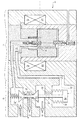
図1は、電気作動弁2を示し、より正確には、電磁機械作動弁を示している。弁2は、加圧流体、例えばガス状流体を循環させることができる。弁2は図1では閉状態で示されており、非通電時に弁は閉状態を保つ。しかし、弁2を、非動作時に開状態を保ち、通電時に閉じるように構成することもできる。
FIG. 1 shows an electrically actuated
弁2は、流体の分配を可能にする分配部4と、分配部4を制御する調整部6すなわち制御部6とを含む。弁2は、できれば分配部及び調整部に共通の、または2つの部分で形成された本体8を含むことができる。調整部6は、強磁性フレーム9を含むことができ、それによって調整部6に磁気回路を形成することができる。フレーム9は、内部チャンバを有する材料ブロックを形成することができる。弁2は、分配部4及び調整部6に共通の入口ポート10を有する。
The
分配部4は分配通路12を含み、弁座を含む分配部入口部分14は、分配通路12によって分配部出口部分16またはユーザポートに連通されている。分配通路12は、任意で、できれば弁座を含む排気ポート18を含み、その場合、入口部分14と排気ポート18との間に出口部分16が配置される。分配部4はさらに、分配部4の各弁座と協働して弁座を塞ぐ分配弁(20;22)を含む。分配弁(20;22)は互いに対して固定されており、ばね24によって閉位置に保持される。
The distributor 4 includes a
分配弁(20;22)は、弁2の加圧流体の圧力によって作動される分配ピストン26によって制御される。ピストン26は、ベローズ28を有するピストン26であるか、または対応する径のボア内に挿入されるピストンであり得る。オリフィス30を用いてベローズ28の内部を近くの排気ポート18に連通させることができる。ピストン26は、チャンバ32内に収容されており、チャンバ32内の圧力の変化がピストン26に並進運動を起こさせ、この並進運動は、ロッド34を介して分配弁(20;22)に伝えられる。ピストンのチャンバ32内の圧力は、調整部6によって制御される。ピストン26は、機械、油圧/空気圧による操作方式が可能である。
The distribution valve (20; 22) is controlled by a
調整部6は、弁座を含む調整部入口部分38と、少なくとも1つの調整部出口部分40すなわち第3の開口40と、両者を互いに連通させる調整通路36とを含む。調整部出口部分40は、管路42を介して、分配部4のピストン26に油圧連通されている。それゆえ、調整部6が開であるときには、弁2の入口ポート10における圧力がピストン26に加えられてピストン26を変位させる。
The adjusting
調整通路36は、弁座を含む調整部排気ポート44を任意で含むことができ、この調整部排気ポート44と調整部入口部分38との間に調整部出口部分40が配置される。調整部6への通電が止まると、調整部排気ポート44によってピストン26への圧力の減少が速められる。
The adjusting
図2は、開位置における弁2を示している。調整部は開であり、加圧流体の圧力を分配部及びその内部に対して作用させることができる。
FIG. 2 shows the
調整部は開であるので、調整部を流体が通過する。調整通路36を介して、調整部の入口部分38及び出口部分40間で圧力が均衡状態に達する。この圧力は管路42を経てピストン26に伝えられ、ピストン26が分配弁(20;22)を変位させる。これらの分配弁(20;22)はこのとき、入口ポート側の弁20がその弁座を開く一方で排気ポート側の弁22がその弁座を閉じるような開位置をとる。分配部入口部分14はこのとき、できれば直接的に、分配部出口部分16に連通されている。弁2は開いている。
Since the adjustment unit is open, the fluid passes through the adjustment unit. The pressure reaches an equilibrium between the
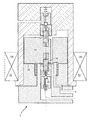
図3は、非動作時、非通電時に閉状態にある調整部6の拡大図を示している。分配部は図示していない。調整部6の閉状態は、調整部の入口部分38及び/または出口部分40を塞ぐことによって達成される。
FIG. 3 shows an enlarged view of the
調整部入口部分38は、当該入口部分を閉じることを可能にする入口側球状体46などの入口側ストッパ46を含む。球状体46は、入口側弁座の上流に配置することができ、そうすることによって流体の圧力によって入口部分38が閉に維持されるので、オートクレーブ特性がもたらされる。この閉の効果に、ばね48が関与し得る。球状体46は、マイクロメートルのオーダーで真球度の許容差を厳しくして製造することができ、それによって漏れが限定されるので、球状体46の選択は有利である。球状体46が弁座に衝当する衝撃により弁座が変形して、シール界面のフィット性が高まり得る。
The
調整部排気ポート44は、弁座の下流側において、当該弁座をシールするために、球状体50などの排気側ストッパ50を含むことができ、排気側ストッパを圧力によって開とすることができる。調整部6の2つの弁座は、互いに逆方向に向けられていることに留意されたい。弁座面は、他方の弁座が位置する方向とは逆方向にストッパ面を受容している。ストッパ(46;50)は、それぞれ別々のチャンバに配置されており、できれば別のチャンバ(この場合は調整通路36)によって隔てられている。図示された状態では、排気側球状体50はその弁座から離間されており、それによってピストンの2つの面が排気ポートの圧力、すなわち圧力均衡状態を維持している。球状体(46;50)は、その耐久性を向上させるため及びその慣性を制限するために、セラミック材料製であり得る。球状体(46;50)の径を1.59mmとし、対応する弁座のオリフィス径を1.12mmとすることができる。これらの寸法は、球状体に対する流体の圧力の影響及び質量の両方を制限し、開に耐える。排気側ばね51は、排気側ストッパを閉に保持するように当該ストッパに作用する。
The adjustment
調整部6は、磁気駆動手段を含む。調整部は、できれば調整通路36及び/または調整部入口側弁座及び/または入口側ストッパ46を取り囲むようなコイル52を含むことができる。コイル52は、軸線方向に互いに隣り合わせに配置されかつ/または一方が他方の中に収まった複数のユニット(複数のソレノイド)を含むことができる。コイル52は、調整部6の入口部分38と出口部分40の間に配置することができる。調整通路36は、磁気回路を形成する磁性フレーム9によって取り囲まれるようにしてもよい。調整通路36は、入口部分38及び出口部分40を有する側面部を含む。結果として、両部分は互いに対してより近接し、より迅速な応答のために圧力損失は制限される。しかし、排気側の出口を磁気的手段に関連して配置することが考えられる。
The
調整部6は、磁気回路の磁束が通るコイル52の内部に配置された磁性プランジャ54を含む。磁性プランジャはストッパ(46;50)間に配置されており、磁性プランジャは、弁座に向かって変位しかつ対応するストッパを押すことにより、それぞれの弁座を開くことができる。調整部は、軸方向の長さが従来よりも短くなる。プランジャが弁座から遠ざかると、ストッパは弁座に向かって変位し、それによって弁座が再び閉じられる。各ストッパは、プランジャに押されるかまたはプランジャに向けて押される。
The
プランジャ54は、調整通路36の可動面を形成することができる。プランジャ54は、磁束力線を方向付けるために強磁性材料を含むことができる。プランジャ54は変位可能であり、プランジャ54の変位により調整部6の開閉が可能になる。プランジャは、入口部分38を排気ポート44に連通させる通路55を有することができる。支配的な圧力及び望ましい応答時間にもよるが、プランジャ54の周りの制御された漏れは圧力の均衡をとるのに十分であり得るので、この通路55はあってもなくてもよい。
The
少なくとも一方または両方のストッパ(46;50)は、球状体と、できれば球状体キャリア56またはストッパキャリア56とを含むことができる。各球状体キャリア56は、一方の面から他方の面への流体循環を可能にするオリフィスを含むことができる。しかし、球状体キャリア56の周りの、恐らく制御された漏れは、分配部のピストンを作動させる圧力に到達するのに十分であり得るので、上記のオリフィスの存在は必須ではない。各球状体キャリア56は、それぞれの球状体(46;50)を中央に配置させることを可能にし、対応するばね(48;51)と球状体との間に介在物を形成することを可能にする。
At least one or both stoppers (46; 50) may comprise a sphere and possibly a
調整部6は、プランジャ54によって駆動されるタペット58を含むことができる。これらのタペット58はそれぞれストッパ(46;50)と協働する。タペット58がストッパ(46;50)をそれぞれの弁座から遠ざかる方向に押すことによって、開状態にし、かつ調整通路36を通して流体を循環させることができる。それぞれの対応するストッパ(46;50)から各タペット58を遠ざけることもでき、後者は、シールを確実にするために弁座に戻る。
The
タペット58は、プランジャ54に対して変位自在に取り付けることができる。プランジャ54は、タペット58の一部と、弾性手段(できれば、ばね62)とを受容するキャビティ60を含むことができる。このようにして、タペット58をプランジャ54に出入りさせることができる。各ストッパ(46;50)は、タペットのばね62によって当該ストッパの弾性手段(48;51)と逆方向に押される。ストッパ(46;50)の一方が開/閉にされたら、できれば連続的に、他方も機械的かつ連鎖的に閉/開にされるようにすることができる。このようにできれば、タペット58とストッパ(46;50)との間の遊びと、さらには接触の衝撃とをなくすことができる。
The
タペット58の弾性手段62は、ストッパ(46;50)の弾性手段(48;51)よりも上位である。タペット58の弾性手段62の剛性をストッパ(46;50)の弾性手段(48;51)の剛性よりも高くすることができる。例えばプリロードを掛けるなどして、逆にすることもできる。
The elastic means 62 of the
タペット58と、したがってストッパ(46;50)とから切り離して、プランジャ54を変位させることができる。プランジャ54は、ストッパ(46;50)を開とするのに必要な変位よりも長い移動距離を有することができる。したがって、プランジャ54の片側のエアギャップ64を調整し、場合により増加させることが可能である。
Disconnecting from the
プランジャ54は、タペット58と協働するストップ面、例えば軸方向ストップ面などを含むことができる。この場合、タペット58の弾性手段62の剛性は、ストッパ(46;50)の弾性手段(48;51)の剛性ほど高くなくてよい。この構成により、機械的な遊びを、ストッパからプランジャ54及びタペット58間にシフトさせることができる。このようにしてストッパ(46;50)との接触が長時間維持される。
磁気短絡を回避するために、少なくとも一方または両方のタペット58を例えば耐磁性材料で製造することができる。タペット58は、各弁座を通過するニードルなどの相対的に肉薄の部分を含むことができる。このとき、弁座と逆の面からストッパ(46;50)を作動させることができる。
In order to avoid magnetic shorts, at least one or both
調整部の弁座は、できれば耐磁性材料製の、結合部材66に形成することができる。結合部材66は、タペットガイド66としても機能し得る。少なくとも一方または両方のタペットガイド66において、対応するタペット58を摺動させるための案内面を設けることができる。タペット58及びタペットガイド66の間または両者によって構成されるペアの少なくとも一方に、例えばタペット58に、通路を形成することができる。この通路は、流体の循環及び/または圧力の均衡を可能にする。
The valve seat of the adjusting portion can be formed on the
調整ばね68は、プランジャ54を閉位置に付勢することができる。調整ばね68は、入口部分及び出口部分を互いに連通させるように構成された端面に接触して配置されている。このばねを調整通路36が通っている。
The
タペット58は、プランジャ54内に進入する。けれども一方で、各タペットの接触面は、隣接するストッパに向けて変位させられ得る。例えば、これらの接触面は、タペットガイドの内部に位置し得る。プランジャは、ガイドの内部に導入されかつガイド内で摺動する支持面を含むことができる。このとき、これらのガイドはプランジャガイドであり得る。
The
図4は、開位置における弁の図である。駆動手段52への通電がなされており、コイル52に電流が循環している。
FIG. 4 is a view of the valve in the open position. The drive means 52 is energized, and a current is circulated through the
磁気的手段52は、フレームの磁気回路において磁束を発生させるので、磁力によって、プランジャ54が入口側ストッパ46に向けて変位させられ、エアギャップ64が埋められることになる。プランジャは、入口側タペット58によって入口側ストッパ46を弁座から押しのけ、それによって調整部6を開とする。開度は一部開であってもよい。これにより、流体の循環や圧力の均衡が可能になり、分配部を作動させて図2に示したように分配部を開とすることができる。
Since the
これまでに示した様々な実施形態を組み合わせることができる。入口ポート(入口部分)、出口ポート(出口部分)及び排気ポートを異なる配置にすることが想定される。入口及び出口は、通路の互いに対向する2面に、及び/またはプランジャに関連して配置することができる。プランジャは、通路に適合したものであり得る。調整部は3つの経路を有しているが、弁と同様に2つの経路にしてもよい。 Various embodiments shown so far can be combined. It is envisaged that the inlet port (inlet part), outlet port (outlet part) and exhaust port are arranged differently. The inlet and outlet can be located on two opposite sides of the passage and / or in relation to the plunger. The plunger can be adapted to the passage. The adjustment unit has three paths, but may have two paths in the same manner as the valve.
Claims (16)
互いに逆方向に向けて配置された2つの弁座と、
各々が前記2つの弁座のうちの一方と協働して該弁座の開閉を可能ならしめる2つのストッパ(46;50)と、
前記2つの弁座を互いに連通させる通路(36)と、
磁場源(52)により駆動可能でありかつ前記2つのストッパをそれぞれの弁座に対して変位させる磁性プランジャ(54)を含む磁気回路とを含み、
前記プランジャが前記2つのストッパ間に配置されており、前記プランジャを前記2つの弁座の一方から遠ざけることによって、当該一方の弁座が対応するストッパによって閉じられるように構成されていることを特徴とする電磁弁。 A solenoid valve (2) for a cryogenic fluid,
Two valve seats arranged in opposite directions,
Two stoppers (46; 50), each of which cooperates with one of the two valve seats to enable opening and closing of the valve seat;
A passage (36) for communicating the two valve seats with each other;
A magnetic circuit that can be driven by a magnetic field source (52) and includes a magnetic plunger (54) that displaces the two stoppers relative to the respective valve seats;
The plunger is disposed between the two stoppers, and when the plunger is moved away from one of the two valve seats, the one valve seat is closed by a corresponding stopper. And solenoid valve.
各タペットが、対応する弁座を通ることによって前記ストッパの一方を変位させ得るように構成されていることを特徴とする請求項1に記載の電磁弁。 Including a tappet (58) cooperating with the stopper;
2. The solenoid valve according to claim 1, wherein each tappet is configured to displace one of the stoppers by passing through a corresponding valve seat.
前記プランジャが好適には少なくとも1つまたは2つのばね(62)を含み、該ばねが、前記タペットを前記プランジャ外に押し出すように構成されていることを特徴とする請求項2に記載の電磁弁。 At least one or both of the tappets are movably mounted relative to the plunger so as to be retractable into the plunger;
3. A solenoid valve according to claim 2, wherein the plunger preferably comprises at least one or two springs (62), the spring being configured to push the tappet out of the plunger. .
各ストッパキャリアが、前記ストッパの開閉中にそれぞれのストッパを対応する弁座に対して中央に配置させるように構成されていることを特徴とする請求項1ないし7のいずれか1項に記載の電磁弁。 Including at least one or two stopper carriers (56);
Each stopper carrier is comprised so that each stopper may be arrange | positioned in the center with respect to a corresponding valve seat during opening and closing of the said stopper. solenoid valve.
前記磁場源の内部に前記2つの弁座の一方が配置されており、前記磁場源を前記通路が通っていることを特徴とする請求項1ないし8のいずれか1項に記載の電磁弁。 Including a magnetic field source (52) such as a coil;
9. The electromagnetic valve according to claim 1, wherein one of the two valve seats is disposed inside the magnetic field source, and the passage passes through the magnetic field source.
当該弁が、前記入口側ストッパが閉でありかつ前記出口側ストッパが開であるような閉位置に前記プランジャを保持するプランジャばね(68)を含むことを特徴とする請求項1ないし9のいずれか1項に記載の電磁弁。 The two stoppers include an inlet side stopper (46) and an outlet side stopper (50),
10. The valve according to claim 1, wherein the valve includes a plunger spring (68) that holds the plunger in a closed position such that the inlet stopper is closed and the outlet stopper is open. The solenoid valve according to claim 1.
前記プランジャが端面を含み、
前記プランジャの前記端面が、前記プランジャが前記通路の前記側面部に向けて変位されているときまたは接触したときに前記入口部分及び前記出口部分間を互いに連通させるように構成されていることを特徴とする請求項1ないし11のいずれか1項に記載の電磁弁。 The passage includes a side portion having an inlet portion and an outlet portion;
The plunger includes an end face;
The end surface of the plunger is configured to communicate between the inlet portion and the outlet portion when the plunger is displaced toward or in contact with the side surface portion of the passage. The electromagnetic valve according to any one of claims 1 to 11.
前記開口が、前記通路によって互いに連通されている前記2つの弁座から離間されていることを特徴とする請求項1ないし12のいずれか1項に記載の電磁弁。 The passage includes an opening (40), such as a third opening;
The electromagnetic valve according to claim 1, wherein the opening is separated from the two valve seats that are communicated with each other by the passage.
当該電磁弁が、前記調整通路に連通された流体分配部(4)をさらに含み、
前記分配部が、
分配通路(12)と、
弁座を含む分配部入口部分(14)と、
弁座を含む分配部出口部分(16)と、
前記分配部入口部分の前記弁座または前記分配部出口部分の前記弁座を選択的に開閉する2つの分配弁(20;22)とを含むことを特徴とする請求項1ないし14のいずれか1項に記載の電磁弁。 The passage is an adjustment passage;
The solenoid valve further includes a fluid distributor (4) in communication with the adjustment passage;
The distributor is
A distribution passage (12);
A distributor inlet portion (14) including a valve seat;
A distributor outlet portion (16) including a valve seat;
15. Two distribution valves (20; 22) for selectively opening and closing the valve seat at the distribution portion inlet portion or the valve seat at the distribution portion outlet portion. The solenoid valve according to item 1.
Applications Claiming Priority (2)
| Application Number | Priority Date | Filing Date | Title |
|---|---|---|---|
| BE2015/5306A BE1023112B1 (en) | 2015-05-19 | 2015-05-19 | AUTOCLAVE CRYOGENIC ELECTROMAGNETIC VALVE FOR SPACE LAUNCHER |
| BE2015/5306 | 2015-05-19 |
Publications (2)
| Publication Number | Publication Date |
|---|---|
| JP2016217536A true JP2016217536A (en) | 2016-12-22 |
| JP6723821B2 JP6723821B2 (en) | 2020-07-15 |
Family
ID=53723957
Family Applications (1)
| Application Number | Title | Priority Date | Filing Date |
|---|---|---|---|
| JP2016099903A Active JP6723821B2 (en) | 2015-05-19 | 2016-05-18 | Solenoid valve for low temperature high pressure steam for spacecraft launching equipment |
Country Status (4)
| Country | Link |
|---|---|
| US (1) | US9964228B2 (en) |
| EP (1) | EP3096053B1 (en) |
| JP (1) | JP6723821B2 (en) |
| BE (1) | BE1023112B1 (en) |
Families Citing this family (2)
| Publication number | Priority date | Publication date | Assignee | Title |
|---|---|---|---|---|
| CN106945851A (en) * | 2017-02-18 | 2017-07-14 | 河南农业大学 | A kind of heat radiation propeller based on electronic kinetic energy |
| JP2019070602A (en) * | 2017-10-10 | 2019-05-09 | 株式会社Personal AI | Method for automatically selecting and determining oil supply, gas filling and electricity charging places when oil supply, gas filling and electricity charging are required in automatic drive |
Citations (3)
| Publication number | Priority date | Publication date | Assignee | Title |
|---|---|---|---|---|
| US3371684A (en) * | 1963-09-11 | 1968-03-05 | Dupont S T | Pneumatic or the like valve control arrangement |
| JPS50131021U (en) * | 1974-04-10 | 1975-10-28 | ||
| JP2014506663A (en) * | 2011-02-16 | 2014-03-17 | スネクマ | Three-way valve |
Family Cites Families (10)
| Publication number | Priority date | Publication date | Assignee | Title |
|---|---|---|---|---|
| US3040775A (en) * | 1960-01-04 | 1962-06-26 | Gen Controls Co | Solenoid operated four-way valve |
| CH469928A (en) * | 1968-01-19 | 1969-03-15 | Lucifer Sa | Valve comprising at least one floating mounted valve |
| US4067357A (en) * | 1974-06-14 | 1978-01-10 | Herion-Werke Kg | Pilot-operated directional control valve |
| AU510090B2 (en) * | 1975-08-05 | 1980-06-05 | Honda Giken Kogyo Kabushiki Kaisha | Spark timing apparatus |
| FR2487942B1 (en) * | 1980-07-29 | 1985-06-21 | Ind Meca Pour Fluides | THREE-WAY VALVE |
| JPS6084404A (en) * | 1983-06-02 | 1985-05-13 | Seiichi Ito | Servo valve |
| DE8408052U1 (en) * | 1984-03-16 | 1985-09-19 | Linde Ag, 6200 Wiesbaden | Electro-magnetic valve |
| US4987923A (en) * | 1989-06-22 | 1991-01-29 | Allied-Signal Inc. | Solenoid valve |
| JP3035999B2 (en) * | 1990-06-29 | 2000-04-24 | 株式会社デンソー | Vehicle brake control device and throttle control valve |
| US5174336A (en) * | 1991-05-31 | 1992-12-29 | Allied-Signal Inc. | General purpose fluid control valve |
-
2015
- 2015-05-19 BE BE2015/5306A patent/BE1023112B1/en not_active IP Right Cessation
-
2016
- 2016-05-10 US US15/150,463 patent/US9964228B2/en active Active
- 2016-05-13 EP EP16169668.7A patent/EP3096053B1/en active Active
- 2016-05-18 JP JP2016099903A patent/JP6723821B2/en active Active
Patent Citations (3)
| Publication number | Priority date | Publication date | Assignee | Title |
|---|---|---|---|---|
| US3371684A (en) * | 1963-09-11 | 1968-03-05 | Dupont S T | Pneumatic or the like valve control arrangement |
| JPS50131021U (en) * | 1974-04-10 | 1975-10-28 | ||
| JP2014506663A (en) * | 2011-02-16 | 2014-03-17 | スネクマ | Three-way valve |
Also Published As
| Publication number | Publication date |
|---|---|
| BE1023112A1 (en) | 2016-11-23 |
| US20160341328A1 (en) | 2016-11-24 |
| JP6723821B2 (en) | 2020-07-15 |
| US9964228B2 (en) | 2018-05-08 |
| EP3096053A1 (en) | 2016-11-23 |
| BE1023112B1 (en) | 2016-11-23 |
| EP3096053B1 (en) | 2020-06-10 |
Similar Documents
| Publication | Publication Date | Title |
|---|---|---|
| US20120080110A1 (en) | Three-Way Valves and Fuel Injectors Using the Same | |
| US20170299088A1 (en) | Bypass valve and expander unit having a bypass valve | |
| US20120235777A1 (en) | Electromagnetic actuating device | |
| US9915360B2 (en) | Electromagnetic valve for high-pressure cryogenic gas | |
| JPH01290960A (en) | Electronic control type fuel injector | |
| US9228459B2 (en) | Actuator for axial displacement of a gas exchange valve in a combustion engine | |
| US6089197A (en) | Electromagnetic actuator for an engine valve, including an integrated valve slack adjuster | |
| JP6723821B2 (en) | Solenoid valve for low temperature high pressure steam for spacecraft launching equipment | |
| US3451429A (en) | Control valve providing means for minimizing seat wear | |
| KR20170038781A (en) | Speed controller | |
| KR102518266B1 (en) | Solenoid valve for gas | |
| CN110214225B (en) | Solenoid valve device for a fuel injector for injecting liquid and/or gaseous fuel | |
| CN208831849U (en) | Electromagnetic barriers valve gear | |
| US3254675A (en) | Multi-purpose solenoid-pilot valve assembly | |
| KR101966876B1 (en) | Valve | |
| JP2010112448A (en) | Shift valve | |
| US10746064B2 (en) | Multi-way valve as well as actuator comprising such a multi-way valve | |
| US10119426B2 (en) | Slide valve for a waste heat recovery system | |
| JP7751728B2 (en) | Solenoid valve and hydrogen tank system equipped with solenoid valve | |
| WO2015151964A1 (en) | Valve device | |
| US20190107210A1 (en) | Spool valve | |
| JP7394825B2 (en) | In particular, an electromagnetic actuator for opening and closing a valve arrangement, a valve arrangement with such an electromagnetic actuator, an adjustable vibration damper with such an electromagnetic actuator, and a motor vehicle with such a vibration damper. | |
| RU2634342C2 (en) | Shut-off electro-magnetic valve | |
| JP6649116B2 (en) | Pressure fluid control device | |
| EP3283798A1 (en) | Multi-way valve as well as actuator comprising such a multi-way valve |
Legal Events
| Date | Code | Title | Description |
|---|---|---|---|
| A621 | Written request for application examination |
Free format text: JAPANESE INTERMEDIATE CODE: A621 Effective date: 20190426 |
|
| A977 | Report on retrieval |
Free format text: JAPANESE INTERMEDIATE CODE: A971007 Effective date: 20200318 |
|
| A131 | Notification of reasons for refusal |
Free format text: JAPANESE INTERMEDIATE CODE: A131 Effective date: 20200331 |
|
| A521 | Request for written amendment filed |
Free format text: JAPANESE INTERMEDIATE CODE: A523 Effective date: 20200605 |
|
| TRDD | Decision of grant or rejection written | ||
| A01 | Written decision to grant a patent or to grant a registration (utility model) |
Free format text: JAPANESE INTERMEDIATE CODE: A01 Effective date: 20200616 |
|
| A61 | First payment of annual fees (during grant procedure) |
Free format text: JAPANESE INTERMEDIATE CODE: A61 Effective date: 20200624 |
|
| R150 | Certificate of patent or registration of utility model |
Ref document number: 6723821 Country of ref document: JP Free format text: JAPANESE INTERMEDIATE CODE: R150 |
|
| R250 | Receipt of annual fees |
Free format text: JAPANESE INTERMEDIATE CODE: R250 |
|
| R250 | Receipt of annual fees |
Free format text: JAPANESE INTERMEDIATE CODE: R250 |
|
| R250 | Receipt of annual fees |
Free format text: JAPANESE INTERMEDIATE CODE: R250 |