JP2016211406A - Air cleaner - Google Patents
Air cleaner Download PDFInfo
- Publication number
- JP2016211406A JP2016211406A JP2015094554A JP2015094554A JP2016211406A JP 2016211406 A JP2016211406 A JP 2016211406A JP 2015094554 A JP2015094554 A JP 2015094554A JP 2015094554 A JP2015094554 A JP 2015094554A JP 2016211406 A JP2016211406 A JP 2016211406A
- Authority
- JP
- Japan
- Prior art keywords
- air
- end member
- duct
- air cleaner
- expansion space
- Prior art date
- Legal status (The legal status is an assumption and is not a legal conclusion. Google has not performed a legal analysis and makes no representation as to the accuracy of the status listed.)
- Granted
Links
Images


Classifications
-
- B—PERFORMING OPERATIONS; TRANSPORTING
- B01—PHYSICAL OR CHEMICAL PROCESSES OR APPARATUS IN GENERAL
- B01D—SEPARATION
- B01D46/00—Filters or filtering processes specially modified for separating dispersed particles from gases or vapours
- B01D46/42—Auxiliary equipment or operation thereof
- B01D46/4236—Reducing noise or vibration emissions
-
- B—PERFORMING OPERATIONS; TRANSPORTING
- B01—PHYSICAL OR CHEMICAL PROCESSES OR APPARATUS IN GENERAL
- B01D—SEPARATION
- B01D46/00—Filters or filtering processes specially modified for separating dispersed particles from gases or vapours
- B01D46/0002—Casings; Housings; Frame constructions
- B01D46/0005—Mounting of filtering elements within casings, housings or frames
-
- B—PERFORMING OPERATIONS; TRANSPORTING
- B01—PHYSICAL OR CHEMICAL PROCESSES OR APPARATUS IN GENERAL
- B01D—SEPARATION
- B01D46/00—Filters or filtering processes specially modified for separating dispersed particles from gases or vapours
- B01D46/0039—Filters or filtering processes specially modified for separating dispersed particles from gases or vapours with flow guiding by feed or discharge devices
- B01D46/0041—Filters or filtering processes specially modified for separating dispersed particles from gases or vapours with flow guiding by feed or discharge devices for feeding
- B01D46/0043—Filters or filtering processes specially modified for separating dispersed particles from gases or vapours with flow guiding by feed or discharge devices for feeding containing fixed gas displacement elements or cores
-
- B—PERFORMING OPERATIONS; TRANSPORTING
- B01—PHYSICAL OR CHEMICAL PROCESSES OR APPARATUS IN GENERAL
- B01D—SEPARATION
- B01D46/00—Filters or filtering processes specially modified for separating dispersed particles from gases or vapours
- B01D46/10—Particle separators, e.g. dust precipitators, using filter plates, sheets or pads having plane surfaces
-
- Y—GENERAL TAGGING OF NEW TECHNOLOGICAL DEVELOPMENTS; GENERAL TAGGING OF CROSS-SECTIONAL TECHNOLOGIES SPANNING OVER SEVERAL SECTIONS OF THE IPC; TECHNICAL SUBJECTS COVERED BY FORMER USPC CROSS-REFERENCE ART COLLECTIONS [XRACs] AND DIGESTS
- Y02—TECHNOLOGIES OR APPLICATIONS FOR MITIGATION OR ADAPTATION AGAINST CLIMATE CHANGE
- Y02T—CLIMATE CHANGE MITIGATION TECHNOLOGIES RELATED TO TRANSPORTATION
- Y02T10/00—Road transport of goods or passengers
- Y02T10/10—Internal combustion engine [ICE] based vehicles
- Y02T10/12—Improving ICE efficiencies
Abstract
Description
本発明は、通気経路の途中に設けられ、通気経路の内部を通流する空気をろ過するエアクリーナに関する。 The present invention relates to an air cleaner that is provided in the middle of a ventilation path and filters air flowing through the inside of the ventilation path.
エアクリーナは、自動車用内燃機関の吸気システムや、空調システム・冷却風送風システムなどの一連の通気経路に使用されている。このようなエアクリーナを有する通気経路において、エンジンやファンやモータなどを騒音源とする騒音が通気経路内を伝播したり、エアクリーナに接続されるダクト系に気柱共鳴が発生したりするので、かねてから騒音の低減が望まれていた。 The air cleaner is used for a series of ventilation paths such as an intake system of an internal combustion engine for an automobile, an air conditioning system, and a cooling air blowing system. In such a ventilation path with an air cleaner, noise that originates from the engine, fan, motor, etc. propagates through the ventilation path, or air column resonance occurs in the duct system connected to the air cleaner. Reduction of noise was desired.
通気経路を伝播する騒音を低減する技術としては、通気経路中のエアクリーナそのものを拡径チャンバーとして活用する技術や、ダクトやエアクリーナにヘルムホルツレゾネータなどの共鳴型消音器を設けるものや、吸音材を設ける技術などが開発・応用されている。 Technologies to reduce the noise that propagates through the ventilation path include the use of the air cleaner itself in the ventilation path as a diameter expansion chamber, the installation of a resonance silencer such as a Helmholtz resonator in the duct or air cleaner, and the provision of sound absorbing materials. Technology is being developed and applied.
例えば、特許文献1には、エアクリーナと吸気ダクトの連結部に吸音材を設ける技術が開示されており、特許文献2には、エアクリーナのケース内周面に沿って吸音材を配置し、非透水性の膜で被覆する技術が開示されている。
For example,
また、エアクリーナに接続されるダクト系に生ずる気柱共鳴を抑制する技術として、非通気性素材で形成されるダクト壁の一部に、通気性を有する部分を設けて、ダクト系の気柱共鳴を予防して、ダクトを伝播する騒音の低減を図る技術、いわゆるポーラスダクトと呼ばれる技術が知られている。例えば、ポーラスダクトとして、特許文献3に記載されたような技術が知られている。この技術は、非通気性のダクト壁の中間部に穴を設けて、適度な通気性を有する不織布などの多孔質材を、それらの穴を覆うように取付け、ダクト内部空間と外部空間とが多孔質材を通じて連通するようにした技術である。さらに、特許文献3に記載のポーラスダクトにおいては、ダクト本体の壁面から突出する小筒部を設け、小筒部先端の開口部に不織布が熱溶着されている。このようなダクトにおいては、多孔質材の通気度を調整することにより、ダクト系に生ずる気柱共鳴の発生を防止しながら、ダクト系を伝播する騒音の低減を図ることができるとともに、不織布の取り付けがしやすくなり、さらに、ダクトの通気抵抗が低減できるという効果が得られる。
In addition, as a technology to suppress air column resonance that occurs in the duct system connected to the air cleaner, a part of the duct wall formed of a non-breathable material is provided with a portion having air permeability so that the air column resonance of the duct system is achieved. A technique for preventing noise and reducing noise propagating through a duct, that is, a so-called porous duct is known. For example, a technique described in
特許文献1,2に記載された技術は、吸音材を用いた消音技術であり、一般に、これら技術では、エアクリーナに接続されるダクト系に生ずる気柱共鳴の抑制を図ることは困難である。
The techniques described in
また、特許文献3に記載された技術は、吸気ダクトの気柱共鳴を防止可能な技術であるが、吸気ダクトの中間部のダクト壁に穴を設けることを前提とした技術である。そのため、ダクト壁に設けられた穴から、空気が漏洩もしくは、侵入してくるという問題がある。例えば、特許文献3の技術のダクトがエアクリーナに接続されて、自動車用エンジンに空気を供給するための吸気ダクトとして用いられると、ダクト壁に設けられた穴から、エンジンルーム内で暖められた空気が吸気ダクト内に侵入してしまい、吸気温度が高くなってエンジンの出力低下を招くおそれがある。
The technique described in
すなわち、特許文献1,2の従来技術においては、エアクリーナに接続される通気ダクトの気柱共鳴を防止できないという問題がある一方で、特許文献3の従来技術においては、本来空気を取り入れたい部分(エンジン用吸気ダクトでいえば吸気口)以外の部分に開口があるため、その開口部でダクト内外の空気の出入りが起こってしまうという問題があった。
本発明の目的は、特許文献3のダクトとは別の技術手段により、エアクリーナに接続されるダクトの気柱共鳴を抑制できるエアクリーナを提供することにある。
That is, in the prior arts of
The objective of this invention is providing the air cleaner which can suppress the air column resonance of the duct connected to an air cleaner by the technical means different from the duct of
発明者は、鋭意検討の結果、特定の通気性材料により筒状に形成された部材(開口端部材)を、エアクリーナの吸気口もしくは排気口の内側に一体化し、開口端部材の内周側空間と外周側空間が直接つながっているように構成すると、上記課題が解決することを知見し、本発明を完成させた。 As a result of intensive studies, the inventor integrated a member (opening end member) formed in a cylindrical shape with a specific air-permeable material into the inside of the air inlet or exhaust port of the air cleaner, and the inner peripheral space of the opening end member. It has been found that the above-mentioned problems can be solved by configuring so that the outer peripheral side space is directly connected to the outer peripheral space, and the present invention has been completed.
本発明は、一連の通気経路の途中に設けられ、通流する空気をろ過するエアクリーナであって、エアクリーナは、拡張空間を画定するケースと、フィルタエレメントとを有し、フィルタエレメントにより前記拡張空間は上流側拡張空間と下流側拡張空間に画定され、前記ケースには、上流側ダクトを上流側拡張空間に連絡するように接続するための吸気口と、下流側ダクトを下流側拡張空間に連絡するように接続するための排気口とが設けられ、さらに、エアクリーナは、通気性を有する材料により筒状に形成された開口端部材を有しており、前記吸気口には、開口端部材が、上流側拡張空間に突出するように、かつ、吸気口のダクト壁を延長するように設けられており、前記筒状の開口端部材の内周側の空間と外周側の空間は、上流側拡張空間として直接つながっており、前記開口端部材の径をD、長さをLとして、0.25D≦L≦2.0Dであり、前記開口端部材を構成する通気性材料の透気度が、JIS P8117 に規定されるガーレー式試験法に準拠した方法で測定して、0.3〜100秒/300ccの範囲にあるエアクリーナである(第1発明)。 The present invention is an air cleaner that is provided in the middle of a series of ventilation paths and filters air flowing therethrough, and the air cleaner includes a case that defines an expansion space and a filter element, and the expansion space is formed by the filter element. Is defined by an upstream expansion space and a downstream expansion space, and the case has an intake port for connecting the upstream duct to communicate with the upstream expansion space, and the downstream duct communicates with the downstream expansion space. The air cleaner has an opening end member formed in a cylindrical shape with a material having air permeability, and the opening end member has an opening end member. The inner wall and the outer space of the cylindrical opening end member are arranged on the upstream side so as to project into the upstream expansion space and extend the duct wall of the intake port. Expansion Are directly connected to each other, the diameter of the opening end member is D, the length is L, and 0.25D ≦ L ≦ 2.0D, and the air permeability of the air-permeable material constituting the opening end member is It is an air cleaner in the range of 0.3 to 100 seconds / 300 cc, as measured by a method based on the Gurley test method specified in JIS P8117 (first invention).
あるいは、本発明は、一連の通気経路の途中に設けられ、通流する空気をろ過するエアクリーナであって、エアクリーナは、拡張空間を画定するケースと、フィルタエレメントとを有し、フィルタエレメントにより前記拡張空間は上流側拡張空間と下流側拡張空間に画定され、前記ケースには、上流側ダクトを上流側拡張空間に連絡するように接続するための吸気口と、下流側ダクトを下流側拡張空間に連絡するように接続するための排気口とが設けられ、さらに、エアクリーナは、通気性を有する材料により筒状に形成された開口端部材を有しており、前記排気口には、開口端部材が、下流側拡張空間に突出するように、かつ、排気口のダクト壁を延長するように設けられており、前記筒状の開口端部材の内周側の空間と外周側の空間は、下流側拡張空間として直接つながっており、前記開口端部材の径をD、長さをLとして、0.25D≦L≦2.0Dであり、前記開口端部材を構成する通気性材料の透気度が、JIS P8117 に規定されるガーレー式試験法に準拠した方法で測定して、0.3〜100秒/300ccの範囲にあるエアクリーナである(第2発明)。
さらに、第1発明もしくは第2発明においては、開口端部材の通気性材料の厚みが0.5〜5mmの範囲にあることが好ましい(第3発明)。さらに第3発明においては、開口端部材には、補強体が一体化されていることが好ましい(第4発明)。
Alternatively, the present invention is an air cleaner that is provided in the middle of a series of ventilation paths and filters flowing air, and the air cleaner includes a case that defines an expansion space and a filter element, and the filter element The expansion space is defined by an upstream expansion space and a downstream expansion space, and the case has an inlet for connecting the upstream duct so as to communicate with the upstream expansion space, and the downstream duct is connected to the downstream expansion space. The air cleaner has an opening end member formed in a cylindrical shape from a material having air permeability, and the exhaust port has an opening end. The members are provided so as to protrude into the downstream expansion space and extend the duct wall of the exhaust port, and the space on the inner peripheral side and the space on the outer peripheral side of the cylindrical opening end member are: Directly connected as a flow-side expansion space, where the diameter of the open end member is D and the length is L, 0.25D ≦ L ≦ 2.0D, and the air permeability of the breathable material constituting the open end member This is an air cleaner whose degree is in the range of 0.3 to 100 seconds / 300 cc as measured by a method based on the Gurley test method specified in JIS P8117 (second invention).
Furthermore, in the first invention or the second invention, it is preferable that the thickness of the breathable material of the open end member is in the range of 0.5 to 5 mm (third invention). Furthermore, in the third invention, it is preferable that a reinforcing body is integrated with the opening end member (fourth invention).
本発明のエアクリーナ(第1発明)によれば、エアクリーナに接続される上流側ダクトの気柱共鳴が抑制でき、特定の周波数におけるダクトの騒音の増大を抑制できる。また、第2発明によれば、エアクリーナに接続される下流側ダクトの気柱共鳴が抑制でき、特定の周波数におけるダクトの騒音の増大を抑制できる。 According to the air cleaner (first invention) of the present invention, the air column resonance of the upstream duct connected to the air cleaner can be suppressed, and an increase in noise of the duct at a specific frequency can be suppressed. In addition, according to the second invention, air column resonance in the downstream duct connected to the air cleaner can be suppressed, and an increase in duct noise at a specific frequency can be suppressed.
さらに、第3発明においては、開口端部材の通気性材料の厚みが0.5〜5mmという薄いものであるにも関わらず、1000Hz以下の周波数領域のダクトの気柱共鳴を抑制しうる。また、第4発明のように、開口端部材に補強体が一体化されていると、開口端部材の変形が未然に防止される。
Furthermore, in the third invention, the air column resonance of the duct in the frequency region of 1000 Hz or less can be suppressed even though the thickness of the breathable material of the open end member is as thin as 0.5 to 5 mm. Further, when the reinforcing body is integrated with the opening end member as in the fourth invention, the opening end member is prevented from being deformed.
以下図面を参照しながら、自動車のエンジンに供給される空気をろ過するエアクリーナを例として、発明の実施形態について説明する。発明は以下に示す個別の実施形態に限定されるものではなく、その形態を変更して実施することもできる。図1に、発明の第1実施形態のエアクリーナ1を示す。図1では、エアクリーナ1を断面図で示している。
エアクリーナ1は、ロワケース11とアッパケース12と、フィルタエレメント13と、開口端部材14を有している。アッパケース12とロワケース11とは組み合わされていつの中空のケースを構成し、ケースにより通気経路中に拡張空間が画定される。フィルタエレメント13は、エレメントの周縁部がアッパケース12とロワケース11の間に挟持されるように配置されて、フィルタエレメント13により前記拡張空間は上流側拡張空間SUと下流側拡張空間SLに画定されている。フィルタエレメント13の周縁部が挟持される部分は、必要に応じシールされる。
Embodiments of the invention will be described below with reference to the drawings, taking an air cleaner that filters air supplied to an automobile engine as an example. The invention is not limited to the individual embodiments shown below, and can be carried out by changing the form. FIG. 1 shows an
The
ロワケース11には、吸気口111が形成されている。吸気口111には、上流側ダクト(図示せず)が接続され、上流側ダクトの内部空間が、上流側拡張空間SUに連絡している。一方、アッパケース12には、排気口121が形成されている。排気口121には、下流側ダクト(図示せず)が接続され、下流側ダクトの内部空間が、下流側拡張空間SLに連絡している。上流側ダクトとエアクリーナ1と下流側ダクトが接続されることによって、一連の通気経路が構成され、空気がろ過されて、エンジンへと導かれる。
エアクリーナ1は、必要に応じ、取付け部材や、消音器(例えば共鳴型消音器等)を備えてもよい。また、エアクリーナを構成するケースやフィルタエレメントやシール材等の具体的構成は特に限定されず、公知の構成を採用できる。
An
The
ロワケース11やアッパケース12は、非通気性の材料により箱状に形成されている。非通気性の材料としては、例えば、熱可塑性樹脂や、熱硬化性樹脂、金属などが例示される。本実施形態のロワケース11及びアッパケース12は、ポリプロピレン樹脂を射出成形することにより成形されている。また、上流側ダクトや下流側ダクトは、通常、熱可塑性樹脂やゴムなどの非通気性材料により管状に形成される。
The
開口端部材14は、ロワケース11の内側に、吸気口111に連続するように一体化されている。一体化は、接着や粘着、溶着のほか、インサート成形、はめ込みやバンド、ピンなどによる機械的接合(係合や係止による接合)によればよい。開口端部材14と吸気口111とを嵌合させて、両者の間に隙間が生じないように両者を接合一体化することが好ましい。
The
開口端部材14は、通気性を有する材料により筒状に形成されている。通気性材料としては、不織布や発泡樹脂(発泡スポンジ)、ろ紙などが例示される。発泡樹脂を使用する場合は、連続気泡構造を有する発泡樹脂であることが好ましい。通気性材料がろ紙や不織布である場合には、バインダなどを含浸させて透気度を調整し、材料のコシを高めて、開口端部材14の形状保持性を高めることが好ましい。本実施形態においては、不織布を筒状に加工して開口端部材14が形成されている。
The
開口端部材14は、吸気口111のダクト壁を上流側拡張空間SU内に延長するような筒状に形成されている。本実施形態では、開口端部材14の外周面は吸気口111の内周面と略同等の直径Dの円筒状に形成されて、両者が嵌合されている。
The
また、筒状の開口端部材14の内周側の空間SIと外周側の空間SOとは、上流側拡張空間SUとして直接つながっている。すなわち、開口端部材14は上流側拡張空間SU内に突出するように設けられており、開口端部材14の内周面及び外周面が、上流側拡張空間SUに面している。
Further, the space SI on the inner peripheral side of the cylindrical opening
エアクリーナ1においては、開口端部材14の部分が上流側ダクトの末端に位置し、通気性のダクト壁を構成することになる。また、吸気口111の部分は上流側ダクトと同じく非通気性のダクト壁を構成する。
エアクリーナ1を一連の通気経路に設けると、上流側ダクトは、吸気口111までの部分が非通気性のダクト壁を有するようになり、吸気口に隣接する開口端部材14の部分が通気性のダクト壁として、エアクリーナの拡張空間内に突出して設けられた構成となる。
In the
When the
開口端部材14の形状についてより詳細に説明する。開口端部材14は、径をD、長さをLとして、0.25D≦L≦2.0Dとなるように設けられる。ここで、径Dとは、筒状の開口端部材14の断面の代表径のことであり、円形断面であれば直径を、楕円断面であれば長径を、矩形断面であれば長辺の長さをいう。また、長さLとは、図1に示したように、開口端部材14のうち、吸気口111と嵌合していない部分の管軸方向の長さをいう。径Dと長さLは、0.5D≦L≦1.5Dとすることが特に好ましい。通気性を有する部分の長さLが短いと、後述する共鳴防止効果が得られにくい。また、通気性を有する部分の長さLを長く(L>2.0D)しても、共鳴防止効果のさらなる向上が見られない一方で開口端部材14の部分の形状維持やエアクリーナの通気抵抗の点で不利である。
The shape of the
開口端部材14を構成する通気性材料の透気度について説明する。通気性材料の透気度は、JIS P8117 に規定されるガーレー式試験法に準拠した方法で測定して、0.3〜100秒/300ccの範囲にある。より好ましくは、0.5〜10秒/300ccの範囲にある。不織布などの通気性材料は、バインダや熱プレスなどを必要に応じ利用して、この範囲に透気度が入るように調整されて、開口端部材14に成形される。
The air permeability of the air permeable material constituting the
開口端部材14を構成する通気性材料の厚みは、0.5〜5mmの範囲にあることが好ましい。本発明によれば、通気性材料がこのように薄いものでありながら1000Hz以下の周波数領域でも共鳴現象の抑制が可能である。通気性材料が薄ければ、開口端部材14が占める空間が小さくなり、エアクリーナ1の省スペース性にもすぐれる。
The thickness of the breathable material constituting the
上記エアクリーナ1は、公知の製造方法を利用して製造することができる。開口端部材14は、例えば、短冊状に切り出した不織布を円筒状に曲げて両端を重ね合わせ、重ね合わせ部分を接着もしくは溶着することにより製造できる。
The
発明の作用及び効果について説明する。
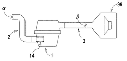
エアクリーナ1によれば、エアクリーナ1を含むように構成された一連の通気経路おいて、吸気口111に接続される上流側ダクトに生じうる気柱共鳴を抑制できる。以下、直径60mm、長さ400mmの上流側ダクトをエアクリーナ1の吸気口111に接続し、直径60mm、長さ300mmの下流側ダクトをエアクリーナ1の排気口121に接続して行った試験結果を示しながら、エアクリーナ1が有する作用及び効果を説明する。なお、以下の説明において、消音効果を示す音響減衰量とは、図3のように、試験対象の上流側ダクト2、エアクリーナ1、下流側ダクト3を、一連の通気経路をなすように接続しつつ、下流側ダクトの末端を、音響加振を行うスピーカ装置99に接続し、スピーカから音を出した際の出口側(上流側ダクトの最上流の末端開口部)音圧Pα(位置αで測定した音圧)と音源側(下流側ダクトの最下流の末端部)の音圧Pβ(位置βで測定した音圧)を測定し、両者の比(Pβ/Pα)を取って、消音効果を評価する指標である。音響減衰量の値が大きいことは、消音効果が大きいことを示し、音響減衰量の値が小さいことは、消音効果が小さいことを示している。
The operation and effect of the invention will be described.
According to the
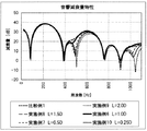
図4には、開口端部材の長さを、L=60mm(L=1.0D)とした第1実施形態のエアクリーナ1(実施例1)の試験結果と、開口端部材を備えない従来技術のエアクリーナ(比較例1)の試験結果の比較を示す。実施例1では、開口端部材14を構成する材料として、透気度3秒/300ccで厚さ1.5mmの不織布を用いた。
FIG. 4 shows the test results of the air cleaner 1 (Example 1) of the first embodiment in which the length of the opening end member is L = 60 mm (L = 1.0D), and the prior art not including the opening end member. The comparison of the test result of this air cleaner (comparative example 1) is shown. In Example 1, a nonwoven fabric having an air permeability of 3 seconds / 300 cc and a thickness of 1.5 mm was used as the material constituting the
図4に示したように、比較例1では、85Hz、395Hz、505Hz、765Hz、909Hzなどにおいて音響減衰量が大きく落ち込む谷がある。これが、通気経路において生ずる気柱共鳴である。85Hzの共鳴は、上流側ダクト2とエアクリーナ1と下流側ダクト3が接続された系全体の共鳴である。上流側ダクト2の共鳴は、395Hz(1次)、765Hz(2次)に現れている。下流側ダクト3の共鳴は、505Hz(1次)、1045Hz(2次)に現れている。気柱共鳴が発生する周波数においては、音響減衰量が小さくなり、騒音の問題が発生しやすい。単純な管の場合には、気柱共鳴は、管の長さが、音の波長λのn/2(n=1,2,・・・)となる周波数で発生する。
As shown in FIG. 4, in Comparative Example 1, there is a valley where the amount of acoustic attenuation drops significantly at 85 Hz, 395 Hz, 505 Hz, 765 Hz, 909 Hz, and the like. This is air column resonance that occurs in the ventilation path. The 85 Hz resonance is the resonance of the entire system in which the
図4に示すように、エアクリーナ1の内部に開口端部材14を設けた実施例1では、上流側ダクト2に対応する気柱共鳴が発生する周波数(395Hz,765Hz)付近でも、音響減衰量の落ち込みが抑えられており、上流側ダクト2の気柱共鳴の発生が抑制されている。また、本実施形態によれば、上流側ダクトの気柱共鳴の抑制にあたって、上流側ダクトに穴を設ける必要がないので、熱気の吸い込みが抑えられる。
As shown in FIG. 4, in Example 1 in which the
以下、本発明における気柱共鳴の抑制の推定メカニズムを説明する。第1実施形態のエアクリーナ1では、特定の透気度を有し、特定の長さを有する開口端部材14を、エアクリーナの吸気口111に設け、上流側ダクト2に接続するようにしている。これを音響的にみると、上流側ダクト2の管の長さが、開口端部材14の存在によってあいまいなものとなると考えられる。比較例1における上流側ダクトは、音響的に見ても明確な管の長さを有しており、その結果、管の共鳴周波数も明瞭となって鋭い気柱共鳴が発生する。一方、実施例1のエアクリーナを用いた系においては、上流側ダクト2の内部とエアクリーナの拡張空間との間の空気の出入りの一部が、開口端部材14の通気性材料を通じて行われるとともに、空気の出入りの残りは、開口端部材14の開口した端部を通じて行われるため、上流側ダクト2から上流側拡張空間SUに対し空気が出入りする箇所があいまいなものとなり、結果、上流側ダクト2の音響的な管の長さがあいまいなものとなる。その結果、音響的管長により決定される共鳴周波数もあいまいなものとなって、鋭い気柱共鳴の発生が抑制されるものと推定される。
Hereinafter, the estimation mechanism of suppression of air column resonance in the present invention will be described. In the
この気柱共鳴抑制のメカニズムは、従来知られていた技術における共鳴防止メカニズムとは、原理が異なるものである。以下それを説明する。
特許文献3の技術のように、ダクトの一部に穴を開け、穴部に多孔質材料を設けた技術(いわゆるポーラスダクト技術)が知られている。この技術によっても、気柱共鳴が抑制されうる。図5に、ダクト9の2次共鳴モードでの音圧分布と、ダクト9に穴や多孔質部材を設ける位置(ポーラスダクトにする部位)の関係を示す。a位置は、ダクト9の全長の1/2の位置、b位置は、ダクト9の全長の1/3の位置、c位置は、ダクト9の全長の1/4の位置に対応している。a位置に穴と多孔質材料を設けてポーラスダクトにしたものを比較例2、b位置に穴と多孔質材料を設けてポーラスダクトにしたものを比較例3、c位置に穴と多孔質材料を設けてポーラスダクトにしたものを比較例4としている。
図6に音響減衰量の比較結果を示す。図6には、通常の直管(比較例1)、ポーラスダクト(比較例2,3,4)の音響減衰量を比較している。
This air column resonance suppression mechanism is different in principle from the resonance prevention mechanism in the conventionally known technology. This will be described below.
A technique (so-called porous duct technique) in which a hole is formed in a part of a duct and a porous material is provided in the hole as in the technique of
FIG. 6 shows a comparison result of the sound attenuation amount. FIG. 6 compares the acoustic attenuation amounts of a normal straight pipe (Comparative Example 1) and a porous duct (Comparative Examples 2, 3, and 4).
図5のようなポーラスダクトの技術においては、気柱共鳴の抑制は、共鳴により音圧が高くなる部位(特に共鳴モードの腹)に穴を開けて、圧力を逃がすことにより、共鳴が起こりにくくなるという原理に基づくものである。そのため、ポーラスダクトでは、共鳴が発生する際の共鳴モードの節の位置と、穴や多孔質部材が設けられる位置がずれていれば、共鳴の抑制効果が得られているが、共鳴時に節にあたる位置に穴や多孔質部材を設けた場合には、ほとんど共鳴抑制効果が得られない。例えば、図5に示すような2次共鳴モードに対しては、b位置やc位置の部分に設ければ効果が期待できるが、a位置に穴や不織布を設けても、節にあたっているため、共鳴防止効果が期待できない。 In the technique of the porous duct as shown in FIG. 5, the suppression of air column resonance is less likely to occur by making a hole in the portion where the sound pressure is increased by resonance (particularly the antinode of the resonance mode) and releasing the pressure. It is based on the principle of becoming. Therefore, in the porous duct, if the position of the node in the resonance mode when resonance occurs is shifted from the position where the hole or the porous member is provided, the resonance suppression effect is obtained, but it hits the node at the time of resonance. When a hole or a porous member is provided at the position, the resonance suppression effect is hardly obtained. For example, for the secondary resonance mode as shown in FIG. 5, an effect can be expected if it is provided at the position of the b position or the c position. The anti-resonance effect cannot be expected.
その結果、図6に示すように、比較例2では、ダクトの2次共鳴(450Hz)と4次共鳴(900Hz)において、a位置が共鳴モードの節に当たるため、ほとんど共鳴抑制効果が得られない。また、比較例3では、3次共鳴(675Hz)において、b位置は共鳴モードの節に当たっており、ほとんど共鳴抑制効果が得られない。また、比較例4では、4次共鳴(900Hz)において、c位置が共鳴モードの節に当たっており、ほとんど共鳴抑制効果が得られない。これが、ポーラスダクト技術による気柱共鳴の抑制の原理およびその効果である。なお、ダクト9の開放端部は、すべての共鳴モードで節にあたる部位となっているため、この部位に穴や不織布を設けても、ポーラスダクト技術の原理により気柱共鳴の抑制を図ることはおよそ期待できない。 As a result, as shown in FIG. 6, in the second comparative example, in the second-order resonance (450 Hz) and fourth-order resonance (900 Hz) of the duct, the position a hits the node of the resonance mode, so that almost no resonance suppression effect is obtained. . Further, in the third comparative example, in the third order resonance (675 Hz), the b position corresponds to the node of the resonance mode, and the resonance suppression effect is hardly obtained. Further, in Comparative Example 4, in the fourth-order resonance (900 Hz), the c position hits the node of the resonance mode, and the resonance suppression effect is hardly obtained. This is the principle and effect of suppression of air column resonance by the porous duct technology. In addition, since the open end of the duct 9 is a part corresponding to a node in all resonance modes, even if a hole or a non-woven fabric is provided in this part, it is not possible to suppress air column resonance by the principle of the porous duct technique. I can't expect it.
グラスウールのような通常の吸音材により、ダクトの気柱共鳴の抑制を図ることは不可能ではないが、現実的には難しい。通常の吸音材の消音の原理は、音の発生により振動的に移動する空気の流れが、吸音材の繊維等の微細な構造による抵抗で減衰され、音のエネルギーが小さくなるという原理に基づくものである。この原理のため、吸音材は、空気の移動の大きな場所に配置されるよう、消音したい周波数に応じて、厚く、広い面積で設けられる必要がある。すなわち、吸音材が薄いと、低周波側の消音効果が期待できない。 Although it is not impossible to suppress the air column resonance of the duct with a normal sound absorbing material such as glass wool, it is practically difficult. The sound-absorbing principle of ordinary sound-absorbing materials is based on the principle that the flow of air that vibrates due to sound generation is attenuated by the resistance of fine structures such as fibers of the sound-absorbing material, and the sound energy is reduced. It is. Due to this principle, the sound absorbing material needs to be provided in a thick and wide area in accordance with the frequency to be silenced so that the sound absorbing material is arranged at a place where air moves greatly. That is, if the sound absorbing material is thin, it is not possible to expect a silencing effect on the low frequency side.
図7に、ダクト8の2次共鳴の音圧分布と、ダクト内周に吸音材を設ける位置の関係を示す。a位置は、ダクト8の全長の1/2の位置、b位置は、ダクト8の全長の1/3の位置、c位置は、ダクト8の全長の1/4の位置に対応している。ダクト8の内周に筒状に吸音材を設ける技術で、a位置に吸音材を設けたものを比較例5、b位置に吸音材を設けたものを比較例6、c位置に吸音材を設けたものを比較例7とした。なお、吸音材の厚みは1.5mmとした。また、筒状の吸音材が設けられる管軸方向の長さはL=1.0Dとした。
FIG. 7 shows the relationship between the sound pressure distribution of the secondary resonance of the
図8に音響減衰量を示すように、1.5mm程度の吸音材では、いずれの共鳴に対しても、a位置、b位置、c位置のいずれに吸音材を設けるかに関わらず、ほとんど共鳴抑制効果が得られない。一般に、5mm以下の吸音材では、1000Hz以下における消音効果はほとんど期待できない。 As shown in FIG. 8, in the sound absorbing material of about 1.5 mm, almost no resonance occurs regardless of whether the sound absorbing material is provided at any of the a position, the b position, and the c position. The suppression effect cannot be obtained. In general, a sound absorbing material of 5 mm or less can hardly be expected to have a silencing effect at 1000 Hz or less.
以上説明したように、実施例1に見られるような本発明の共鳴抑制効果は、従来技術であるいわゆるポーラスダクトの共鳴防止原理や吸音材の消音原理とは、異なる原理、すなわち、管の音響的長さがあいまいになることで明瞭な共鳴が起こらなくなるという原理により生ずる効果である。そのため、通気性素材からなる開口端部材を、従来の原理からしてみればおよそ効果が期待できないような位置や厚さで設けているにも関わらず、通気ダクトの気柱共鳴が抑制できる。 As described above, the resonance suppression effect of the present invention as seen in Example 1 is different from the so-called porous duct resonance prevention principle and the sound absorbing material silencing principle that are conventional techniques, that is, the sound of the pipe. This is an effect caused by the principle that the clear resonance does not occur when the target length becomes ambiguous. Therefore, the air column resonance of the ventilation duct can be suppressed despite the fact that the opening end member made of a breathable material is provided at a position and thickness that cannot be expected from the conventional principle.
図9に、第1実施形態のエアクリーナ1の開口端部材14の長さ(吸気口111に組み付けた際に通気性を有する部分の長さ)Lを変更した際の、音響減衰量の変化を示す。L=0.25D(実施例5)であっても、比較例と比べ、気柱共鳴防止効果がみられる。L=0.5D(実施例2)とすれば、かなりの気柱共鳴防止効果が得られている。また、Lを大きくすることによって、気柱共鳴の防止効果は向上していくが、Lが1.5D(実施例3)を超えL=2.0(実施例4)となっても、あまり気柱共鳴の防止効果が向上しなくなる。したがって、気柱共鳴の防止を図りつつ、開口端部材の小型化を図る観点から、開口端部材14の径Dと長さLの関係を0.25D≦L≦2.0Dとするのが良い。
FIG. 9 shows changes in the amount of acoustic attenuation when the length L of the opening
発明は、上記実施形態に限定されるものではなく、種々の改変をして実施することができる。以下に発明の他の実施形態について説明するが、以下の説明においては、上記実施形態と異なる部分を中心に説明し、同様である部分についてはその詳細な説明を省略する。また、以下に示す実施形態は、その一部を互いに組み合わせて、あるいは、その一部を置き換えて実施できる。 The invention is not limited to the embodiment described above, and can be implemented with various modifications. Although other embodiments of the invention will be described below, in the following description, portions different from the above-described embodiment will be mainly described, and detailed descriptions of the same portions will be omitted. Further, the embodiments described below can be implemented by combining some of them or replacing some of them.
開口端部材の変形例について説明する。開口端部材は、図2に図示した開口端部材4のように、変形を防止するための補強体42を備えていてもよい。この開口端部材4は第1実施形態の開口端部材14のように、吸気口111に一体化されて上流側ダクトの末端部を構成し、同様の効果を発揮する。補強体42は、通気性素材により円筒状に形成された開口端部材本体41の外周に一体化される。補強体42は、開口端部材4のつぶれを防止できるよう、リング状の部位を所定の間隔を隔てて有するような形態であることが好ましい。本実施形態では、補強体42は、軸方向に所定の間隔を隔てて配置されたリング状部分を有するように、格子状に形成されている。また、好ましくは、補強体42は合成樹脂により形成されて溶着や接着により開口端部材本体41に一体化されている。なお、補強体42は、開口端部材本体41が有する通気性を損なわないように、極力細く設けられることが好ましい。
A modification of the open end member will be described. The open end member may include a reinforcing
上記説明においては、エアクリーナ1の開口端部材14が、ロワケース11の吸気口111に取り付けられ、上流側拡張空間SUに突出している実施形態を中心に説明したが、これに限るものではなく、例えば、開口端部材が、アッパケースの排気口に取り付けられ、下流側拡張空間SLに突出しているように設けてもよい。図10に示す第2実施形態のエアクリーナでは、エアクリーナ6はロワケース61、アッパケース62、フィルタエレメント63、開口端部材64を備え、開口端部材64は、アッパケースに設けられた排気口621に、下流側拡張空間SLに向けて突出するように取り付けられている。
In the above description, the opening
この実施形態においても、同様に、開口端部材64が取り付けられる下流側ダクト(図示せず)の共鳴抑制効果が得られる。図11には、この第2実施形態による消音効果を示す。開口端部材64の長さをL=1.0Dとしたものを実施例6、L=0.5Dとしたものを実施例7、L=1.5Dとしたものを実施例8、L=2.0Dとしたものを実施例9、L=0.25Dとしたものを実施例10としている。上流側ダクトや下流側ダクトは、第1実施形態と同様のものを用いた。第2実施形態では、いずれの実施例(実施例6〜10)においても、下流側ダクトの気柱共鳴周波数に対応する505Hz(1次共鳴)、1047Hz(2次共鳴)において、共鳴の抑制効果が得られている。
Also in this embodiment, the resonance suppression effect of the downstream duct (not shown) to which the
開口端部材は、エアクリーナの吸気口と排気口の両方に設けてもよい。図12には、第3実施形態の一例として、L=1.0Dとした開口端部材を、エアクリーナの吸気口と排気口の両方に設けた例(実施例11)の消音効果を示す。実施例11によれば、400Hz近辺から上の周波数における共鳴が、ほとんど抑制されており、良好な消音特性が得られている。 You may provide an opening end member in both the inlet port and exhaust port of an air cleaner. FIG. 12 shows the silencing effect of an example (Example 11) in which an opening end member with L = 1.0D is provided at both the air inlet and the exhaust port of the air cleaner as an example of the third embodiment. According to Example 11, resonance at frequencies above 400 Hz is almost suppressed, and a good silencing characteristic is obtained.
また、発明のエアクリーナは、いわゆる水抜き穴やチューニングホールを備えるものであってもよい。また、エアクリーナは、ヘルムホルツレゾネータや1/4波長共鳴管(サイドブランチ)といった、共鳴型消音器を備えるものであってもよい。 Moreover, the air cleaner of the invention may include a so-called drain hole or tuning hole. The air cleaner may be provided with a resonance silencer such as a Helmholtz resonator or a quarter wavelength resonance tube (side branch).
また、上記実施形態の説明においては、エアクリーナが、自動車用エンジンの吸気経路に使用される実施形態について説明したが、エアクリーナが設けられる一連の通気経路の用途はそれに限定されるものではない。例えば、本発明のエアクリーナは、ハイブリッド自動車や電気自動車に搭載される集合電池に冷却風を送る電池冷却システムの通気経路の一部を構成するために使用できる。また、エアコンディショナーなどの空調システムにおいて、空気を送風するための送風経路の一部を構成するためのエアクリーナとしても使用できる。 In the description of the above embodiment, the air cleaner is used in the intake path of the automobile engine. However, the application of the series of ventilation paths provided with the air cleaner is not limited thereto. For example, the air cleaner of the present invention can be used to configure a part of a ventilation path of a battery cooling system that sends cooling air to an assembled battery mounted on a hybrid vehicle or an electric vehicle. Further, in an air conditioning system such as an air conditioner, it can also be used as an air cleaner for constituting a part of a blowing path for blowing air.
開口端部材を備えるエアクリーナは、空気を送るダクト全般に使用でき、産業上の利用価値が高い。 An air cleaner provided with an open end member can be used for all ducts for sending air, and has high industrial utility value.
1 エアクリーナ
11 ロワケース
111 吸気口
12 アッパケース
121 排気口
13 フィルタエレメント
14 開口端部材
2 上流側ダクト
3 下流側ダクト
4 開口端部材
41 開口端部材本体
42 補強体
8、9 ダクト
99 スピーカ装置
DESCRIPTION OF
Claims (4)
エアクリーナは、拡張空間を画定するケースと、フィルタエレメントとを有し、フィルタエレメントにより前記拡張空間は上流側拡張空間と下流側拡張空間に画定され、
前記ケースには、上流側ダクトを上流側拡張空間に連絡するように接続するための吸気口と、下流側ダクトを下流側拡張空間に連絡するように接続するための排気口とが設けられ、
さらに、エアクリーナは、通気性を有する材料により筒状に形成された開口端部材を有しており、
前記吸気口には、開口端部材が、上流側拡張空間に突出するように、かつ、吸気口のダクト壁を延長するように設けられており、
前記筒状の開口端部材の内周側の空間と外周側の空間は、上流側拡張空間として直接つながっており、
前記開口端部材の径をD、長さをLとして、0.25D≦L≦2.0Dであり、
前記開口端部材を構成する通気性材料の透気度が、JIS P8117 に規定されるガーレー式試験法に準拠した方法で測定して、0.3〜100秒/300ccの範囲にあるエアクリーナ。 An air cleaner that is provided in the middle of a series of ventilation paths and filters the flowing air,
The air cleaner has a case that defines an expansion space, and a filter element, and the expansion space is defined by an upstream expansion space and a downstream expansion space by the filter element,
The case is provided with an intake port for connecting the upstream duct so as to communicate with the upstream expansion space, and an exhaust port for connecting the downstream duct so as to communicate with the downstream expansion space,
Furthermore, the air cleaner has an open end member formed in a cylindrical shape from a material having air permeability,
An opening end member is provided at the intake port so as to protrude into the upstream side expansion space and to extend the duct wall of the intake port.
The space on the inner peripheral side and the space on the outer peripheral side of the cylindrical opening end member are directly connected as an upstream expansion space,
The diameter of the open end member is D and the length is L, and 0.25D ≦ L ≦ 2.0D,
An air cleaner in which the air permeability of the air-permeable material constituting the open end member is in the range of 0.3 to 100 seconds / 300 cc as measured by a method based on the Gurley test method specified in JIS P8117.
エアクリーナは、拡張空間を画定するケースと、フィルタエレメントとを有し、フィルタエレメントにより前記拡張空間は上流側拡張空間と下流側拡張空間に画定され、
前記ケースには、上流側ダクトを上流側拡張空間に連絡するように接続するための吸気口と、下流側ダクトを下流側拡張空間に連絡するように接続するための排気口とが設けられ、
さらに、エアクリーナは、通気性を有する材料により筒状に形成された開口端部材を有しており、
前記排気口には、開口端部材が、下流側拡張空間に突出するように、かつ、排気口のダクト壁を延長するように設けられており、
前記筒状の開口端部材の内周側の空間と外周側の空間は、下流側拡張空間として直接つながっており、
前記開口端部材の径をD、長さをLとして、0.25D≦L≦2.0Dであり、
前記開口端部材を構成する通気性材料の透気度が、JIS P8117 に規定されるガーレー式試験法に準拠した方法で測定して、0.3〜100秒/300ccの範囲にあるエアクリーナ。 An air cleaner that is provided in the middle of a series of ventilation paths and filters the flowing air,
The air cleaner has a case that defines an expansion space, and a filter element, and the expansion space is defined by an upstream expansion space and a downstream expansion space by the filter element,
The case is provided with an intake port for connecting the upstream duct so as to communicate with the upstream expansion space, and an exhaust port for connecting the downstream duct so as to communicate with the downstream expansion space,
Furthermore, the air cleaner has an open end member formed in a cylindrical shape from a material having air permeability,
The exhaust port is provided with an open end member so as to protrude into the downstream expansion space and extend the duct wall of the exhaust port,
The space on the inner peripheral side and the space on the outer peripheral side of the cylindrical opening end member are directly connected as a downstream expansion space,
The diameter of the open end member is D and the length is L, and 0.25D ≦ L ≦ 2.0D,
An air cleaner in which the air permeability of the air-permeable material constituting the open end member is in the range of 0.3 to 100 seconds / 300 cc as measured by a method based on the Gurley test method specified in JIS P8117.
Priority Applications (3)
| Application Number | Priority Date | Filing Date | Title |
|---|---|---|---|
| JP2015094554A JP6452540B2 (en) | 2015-05-07 | 2015-05-07 | Air cleaner |
| CN201510542493.6A CN106110787B (en) | 2015-05-07 | 2015-08-28 | Air cleaner |
| US14/867,617 US9737840B2 (en) | 2015-05-07 | 2015-09-28 | Air cleaner |
Applications Claiming Priority (1)
| Application Number | Priority Date | Filing Date | Title |
|---|---|---|---|
| JP2015094554A JP6452540B2 (en) | 2015-05-07 | 2015-05-07 | Air cleaner |
Publications (2)
| Publication Number | Publication Date |
|---|---|
| JP2016211406A true JP2016211406A (en) | 2016-12-15 |
| JP6452540B2 JP6452540B2 (en) | 2019-01-16 |
Family
ID=57222249
Family Applications (1)
| Application Number | Title | Priority Date | Filing Date |
|---|---|---|---|
| JP2015094554A Active JP6452540B2 (en) | 2015-05-07 | 2015-05-07 | Air cleaner |
Country Status (3)
| Country | Link |
|---|---|
| US (1) | US9737840B2 (en) |
| JP (1) | JP6452540B2 (en) |
| CN (1) | CN106110787B (en) |
Families Citing this family (5)
| Publication number | Priority date | Publication date | Assignee | Title |
|---|---|---|---|---|
| JP2018035699A (en) * | 2016-08-29 | 2018-03-08 | トヨタ紡織株式会社 | Air cleaner |
| JP7140644B2 (en) * | 2018-11-16 | 2022-09-21 | タイガースポリマー株式会社 | rectifier structure |
| US11920971B2 (en) | 2020-08-14 | 2024-03-05 | Honeywell International Inc. | Gas flowmeter having inline calibrating |
| US11754429B2 (en) * | 2020-11-11 | 2023-09-12 | Honeywell International Inc. | Multifunctional dust trap |
| EP4234065A1 (en) * | 2022-02-24 | 2023-08-30 | MANN+HUMMEL GmbH | Housing for a filter element and filter system comprising a housing |
Citations (4)
| Publication number | Priority date | Publication date | Assignee | Title |
|---|---|---|---|---|
| JPH10331732A (en) * | 1997-06-03 | 1998-12-15 | Toyota Motor Corp | Air cleaner |
| JP2005076589A (en) * | 2003-09-03 | 2005-03-24 | Honda Motor Co Ltd | Intake device for internal combustion engine |
| JP2009293531A (en) * | 2008-06-05 | 2009-12-17 | Tigers Polymer Corp | Sound absorbing material and sound absorbing duct system |
| JP2015045233A (en) * | 2013-08-27 | 2015-03-12 | トヨタ紡織株式会社 | Air cleaner |
Family Cites Families (15)
| Publication number | Priority date | Publication date | Assignee | Title |
|---|---|---|---|---|
| US3201338A (en) * | 1960-03-28 | 1965-08-17 | Pennington William | Exhaust purifying arrangement |
| US3769780A (en) * | 1971-11-23 | 1973-11-06 | Bendix Corp | Particle filter-sound muffler |
| US4124091A (en) * | 1975-12-24 | 1978-11-07 | Toyota Jidosha Kogyo Kabushiki Kaisha | Silencer for an internal combustion engine |
| US4393652A (en) * | 1980-07-23 | 1983-07-19 | Munro John H | Exhaust system for internal combustion engines |
| JPH0676651A (en) | 1992-08-25 | 1994-03-18 | Showa Electric Wire & Cable Co Ltd | Composite superconductor and manufacture thereof |
| JPH0988749A (en) | 1995-09-28 | 1997-03-31 | Tenetsukusu:Kk | Acoustic absorption duct structural body |
| JP3780553B2 (en) * | 1996-02-28 | 2006-05-31 | 東洋紡績株式会社 | Air filter |
| US6622680B2 (en) | 2000-05-17 | 2003-09-23 | Toyoda Gosei Co., Ltd. | Air intake duct and manufacturing method therefor |
| JP3835117B2 (en) | 2000-05-17 | 2006-10-18 | 豊田合成株式会社 | Intake duct and manufacturing method thereof |
| US6852151B2 (en) * | 2002-06-03 | 2005-02-08 | Siemens Vdo Automotive Inc. | Air cleaner and resonator assembly |
| EP1684891A1 (en) * | 2003-11-20 | 2006-08-02 | Air Institution, Inc. | Exhaust gas filter and filtering system |
| JP4392592B2 (en) * | 2003-12-12 | 2010-01-06 | トヨタ自動車株式会社 | Exhaust silencer |
| US7819223B2 (en) * | 2006-04-03 | 2010-10-26 | Praxair Technology, Inc. | Silencer for adsorption-based gas separation systems |
| AU2008320948B2 (en) * | 2007-11-15 | 2013-08-15 | Donaldson Company, Inc. | Air filter arrangements; assemblies; and, methods |
| CN201858054U (en) * | 2010-09-02 | 2011-06-08 | 太仓市联宏电塑有限公司 | Noise-reduction air filter of automobile |
-
2015
- 2015-05-07 JP JP2015094554A patent/JP6452540B2/en active Active
- 2015-08-28 CN CN201510542493.6A patent/CN106110787B/en not_active Expired - Fee Related
- 2015-09-28 US US14/867,617 patent/US9737840B2/en not_active Expired - Fee Related
Patent Citations (4)
| Publication number | Priority date | Publication date | Assignee | Title |
|---|---|---|---|---|
| JPH10331732A (en) * | 1997-06-03 | 1998-12-15 | Toyota Motor Corp | Air cleaner |
| JP2005076589A (en) * | 2003-09-03 | 2005-03-24 | Honda Motor Co Ltd | Intake device for internal combustion engine |
| JP2009293531A (en) * | 2008-06-05 | 2009-12-17 | Tigers Polymer Corp | Sound absorbing material and sound absorbing duct system |
| JP2015045233A (en) * | 2013-08-27 | 2015-03-12 | トヨタ紡織株式会社 | Air cleaner |
Also Published As
| Publication number | Publication date |
|---|---|
| CN106110787B (en) | 2019-10-01 |
| US9737840B2 (en) | 2017-08-22 |
| US20160325218A1 (en) | 2016-11-10 |
| CN106110787A (en) | 2016-11-16 |
| JP6452540B2 (en) | 2019-01-16 |
Similar Documents
| Publication | Publication Date | Title |
|---|---|---|
| JP6452540B2 (en) | Air cleaner | |
| JP6449095B2 (en) | Ventilation duct | |
| JP2016217147A (en) | Resonator and blower tube including the same | |
| US8439158B2 (en) | Acoustic resonator and sound chamber | |
| US20040226772A1 (en) | Air intake apparatus | |
| WO2017216824A1 (en) | Air cleaner | |
| JP6452543B2 (en) | Air cleaner | |
| JP2009293531A (en) | Sound absorbing material and sound absorbing duct system | |
| JP3802312B2 (en) | Air intake duct | |
| JP5029593B2 (en) | Blower device | |
| JP2002266715A (en) | Air cleaner | |
| JP6659441B2 (en) | Ventilation duct with silencer | |
| JP5778717B2 (en) | Air cleaner | |
| JP2010053763A (en) | Duct | |
| JP2006335125A (en) | Duct of air-conditioner | |
| JP2018035701A (en) | Air cleaner | |
| WO2017216823A1 (en) | Ventilation duct | |
| JP4799442B2 (en) | duct | |
| JP2019035382A (en) | Silencer | |
| JP4727608B2 (en) | Intake silencer and silencer method | |
| JP2006307755A (en) | Intake air noise muffling device | |
| JP5778716B2 (en) | Air cleaner | |
| JP2010275916A (en) | Intake air duct | |
| JP6959181B2 (en) | Sound absorbing structure and duct sound absorbing structure | |
| JP2010002147A (en) | Ventilating duct |
Legal Events
| Date | Code | Title | Description |
|---|---|---|---|
| A621 | Written request for application examination |
Free format text: JAPANESE INTERMEDIATE CODE: A621 Effective date: 20180220 |
|
| A131 | Notification of reasons for refusal |
Free format text: JAPANESE INTERMEDIATE CODE: A131 Effective date: 20181009 |
|
| A521 | Request for written amendment filed |
Free format text: JAPANESE INTERMEDIATE CODE: A523 Effective date: 20181015 |
|
| TRDD | Decision of grant or rejection written | ||
| A01 | Written decision to grant a patent or to grant a registration (utility model) |
Free format text: JAPANESE INTERMEDIATE CODE: A01 Effective date: 20181211 |
|
| A61 | First payment of annual fees (during grant procedure) |
Free format text: JAPANESE INTERMEDIATE CODE: A61 Effective date: 20181211 |
|
| R150 | Certificate of patent or registration of utility model |
Ref document number: 6452540 Country of ref document: JP Free format text: JAPANESE INTERMEDIATE CODE: R150 |