JP2016208513A - Repeating method and corresponding communication network device, system, computer program and computer readable storage medium - Google Patents
Repeating method and corresponding communication network device, system, computer program and computer readable storage medium Download PDFInfo
- Publication number
- JP2016208513A JP2016208513A JP2016084967A JP2016084967A JP2016208513A JP 2016208513 A JP2016208513 A JP 2016208513A JP 2016084967 A JP2016084967 A JP 2016084967A JP 2016084967 A JP2016084967 A JP 2016084967A JP 2016208513 A JP2016208513 A JP 2016208513A
- Authority
- JP
- Japan
- Prior art keywords
- communication
- frame
- interface
- communication interface
- address
- Prior art date
- Legal status (The legal status is an assumption and is not a legal conclusion. Google has not performed a legal analysis and makes no representation as to the accuracy of the status listed.)
- Granted
Links
- 238000004891 communication Methods 0.000 title claims abstract description 237
- 238000000034 method Methods 0.000 title claims abstract description 50
- 238000004590 computer program Methods 0.000 title claims description 3
- 230000015654 memory Effects 0.000 description 9
- 238000013519 translation Methods 0.000 description 7
- 230000005540 biological transmission Effects 0.000 description 6
- 238000010586 diagram Methods 0.000 description 6
- 238000012545 processing Methods 0.000 description 3
- 230000004044 response Effects 0.000 description 3
- 238000006243 chemical reaction Methods 0.000 description 2
- 230000003993 interaction Effects 0.000 description 2
- 230000007246 mechanism Effects 0.000 description 2
- 230000003287 optical effect Effects 0.000 description 2
- 230000008569 process Effects 0.000 description 2
- 230000004913 activation Effects 0.000 description 1
- 238000012790 confirmation Methods 0.000 description 1
- 230000002093 peripheral effect Effects 0.000 description 1
- 239000004065 semiconductor Substances 0.000 description 1
- 230000007704 transition Effects 0.000 description 1
Images


Classifications
-
- H—ELECTRICITY
- H04—ELECTRIC COMMUNICATION TECHNIQUE
- H04W—WIRELESS COMMUNICATION NETWORKS
- H04W88/00—Devices specially adapted for wireless communication networks, e.g. terminals, base stations or access point devices
- H04W88/16—Gateway arrangements
-
- H—ELECTRICITY
- H04—ELECTRIC COMMUNICATION TECHNIQUE
- H04B—TRANSMISSION
- H04B7/00—Radio transmission systems, i.e. using radiation field
- H04B7/14—Relay systems
-
- H—ELECTRICITY
- H04—ELECTRIC COMMUNICATION TECHNIQUE
- H04W—WIRELESS COMMUNICATION NETWORKS
- H04W16/00—Network planning, e.g. coverage or traffic planning tools; Network deployment, e.g. resource partitioning or cells structures
- H04W16/24—Cell structures
- H04W16/26—Cell enhancers or enhancement, e.g. for tunnels, building shadow
-
- H—ELECTRICITY
- H04—ELECTRIC COMMUNICATION TECHNIQUE
- H04L—TRANSMISSION OF DIGITAL INFORMATION, e.g. TELEGRAPHIC COMMUNICATION
- H04L12/00—Data switching networks
- H04L12/66—Arrangements for connecting between networks having differing types of switching systems, e.g. gateways
-
- H—ELECTRICITY
- H04—ELECTRIC COMMUNICATION TECHNIQUE
- H04L—TRANSMISSION OF DIGITAL INFORMATION, e.g. TELEGRAPHIC COMMUNICATION
- H04L61/00—Network arrangements, protocols or services for addressing or naming
- H04L61/09—Mapping addresses
- H04L61/25—Mapping addresses of the same type
-
- H—ELECTRICITY
- H04—ELECTRIC COMMUNICATION TECHNIQUE
- H04L—TRANSMISSION OF DIGITAL INFORMATION, e.g. TELEGRAPHIC COMMUNICATION
- H04L61/00—Network arrangements, protocols or services for addressing or naming
- H04L61/09—Mapping addresses
- H04L61/25—Mapping addresses of the same type
- H04L61/2596—Translation of addresses of the same type other than IP, e.g. translation from MAC to MAC addresses
-
- H—ELECTRICITY
- H04—ELECTRIC COMMUNICATION TECHNIQUE
- H04L—TRANSMISSION OF DIGITAL INFORMATION, e.g. TELEGRAPHIC COMMUNICATION
- H04L61/00—Network arrangements, protocols or services for addressing or naming
- H04L61/50—Address allocation
- H04L61/5007—Internet protocol [IP] addresses
- H04L61/5014—Internet protocol [IP] addresses using dynamic host configuration protocol [DHCP] or bootstrap protocol [BOOTP]
-
- H—ELECTRICITY
- H04—ELECTRIC COMMUNICATION TECHNIQUE
- H04L—TRANSMISSION OF DIGITAL INFORMATION, e.g. TELEGRAPHIC COMMUNICATION
- H04L67/00—Network arrangements or protocols for supporting network services or applications
- H04L67/50—Network services
- H04L67/56—Provisioning of proxy services
- H04L67/562—Brokering proxy services
-
- H—ELECTRICITY
- H04—ELECTRIC COMMUNICATION TECHNIQUE
- H04W—WIRELESS COMMUNICATION NETWORKS
- H04W84/00—Network topologies
- H04W84/02—Hierarchically pre-organised networks, e.g. paging networks, cellular networks, WLAN [Wireless Local Area Network] or WLL [Wireless Local Loop]
- H04W84/04—Large scale networks; Deep hierarchical networks
- H04W84/042—Public Land Mobile systems, e.g. cellular systems
- H04W84/047—Public Land Mobile systems, e.g. cellular systems using dedicated repeater stations
-
- H—ELECTRICITY
- H04—ELECTRIC COMMUNICATION TECHNIQUE
- H04B—TRANSMISSION
- H04B7/00—Radio transmission systems, i.e. using radiation field
- H04B7/24—Radio transmission systems, i.e. using radiation field for communication between two or more posts
- H04B7/26—Radio transmission systems, i.e. using radiation field for communication between two or more posts at least one of which is mobile
-
- H—ELECTRICITY
- H04—ELECTRIC COMMUNICATION TECHNIQUE
- H04L—TRANSMISSION OF DIGITAL INFORMATION, e.g. TELEGRAPHIC COMMUNICATION
- H04L2101/00—Indexing scheme associated with group H04L61/00
- H04L2101/60—Types of network addresses
- H04L2101/618—Details of network addresses
- H04L2101/622—Layer-2 addresses, e.g. medium access control [MAC] addresses
-
- H—ELECTRICITY
- H04—ELECTRIC COMMUNICATION TECHNIQUE
- H04W—WIRELESS COMMUNICATION NETWORKS
- H04W76/00—Connection management
- H04W76/10—Connection setup
- H04W76/12—Setup of transport tunnels
-
- H—ELECTRICITY
- H04—ELECTRIC COMMUNICATION TECHNIQUE
- H04W—WIRELESS COMMUNICATION NETWORKS
- H04W84/00—Network topologies
- H04W84/02—Hierarchically pre-organised networks, e.g. paging networks, cellular networks, WLAN [Wireless Local Area Network] or WLL [Wireless Local Loop]
- H04W84/10—Small scale networks; Flat hierarchical networks
- H04W84/12—WLAN [Wireless Local Area Networks]
Abstract
Description
本開示は、ネットワークのカバレッジの拡張を可能にする中継器のような通信ネットワークデバイスの分野に関係があり、特に、無線インターフェイスを有し、とりわけ、無線ネットワークのカバレッジの拡張を可能にする中継器に関係がある。 The present disclosure relates to the field of communication network devices such as repeaters that allow for extended coverage of a network, and in particular, a repeater that has a radio interface and, inter alia, allows for extended coverage of a wireless network. Is related to
中継方法並びに対応する通信ネットワークデバイス、システム、コンピュータプログラム及びコンピュータ可読記憶媒体が記載される。 A relay method and corresponding communication network device, system, computer program and computer readable storage medium are described.
無線通信エンドデバイス、例えば、スマートフォン、タブレット、パーソナルコンピュータ、又はプリンタのような周辺機器は、今日、広く使用されるようになっている。それらは、無線ネットワーク、例えば、無線ローカルエリアネットワーク(WLAN;wireless local area network)内の他の無線通信デバイスと直接に、又は中間物、すなわち“ブリッジ”デバイスのおかげで、データを交換してよい。他のネットワークへのアクセスは、Wi−Fi(登録商標)又はBluetooth(登録商標)インターフェイスのような無線通信インターフェイスを有するネットワークインターコネクトデバイス(すなわち、“ゲートウェイ”)と、他のネットワーク(例えば、インターネットタイプのネットワークのようなワイドエリアネットワーク(WAN;wide area network))への通信インターフェイスとのおかげで、無線通信デバイスへしばしば提供される。 Peripheral devices such as wireless communication end devices, such as smartphones, tablets, personal computers, or printers, are becoming widely used today. They may exchange data directly with other wireless communication devices in a wireless network, eg, a wireless local area network (WLAN), or thanks to an intermediate or “bridge” device . Access to other networks includes network interconnect devices (ie, “gateways”) having a wireless communication interface, such as a Wi-Fi® or Bluetooth® interface, and other networks (eg, Internet type Often provided to wireless communication devices, thanks to a communication interface to a wide area network (WAN) such as
無線ネットワークのカバレッジエリアを広げるために、通信デバイス(“中継器”又は“拡張器”と呼ばれる。)は、1つのデバイスから送信されたフレームを受信し、それらを他のデバイスへ送信するために、及びその逆のために、無線手段によって通信する2つのデバイスの間の中間デバイスとして使用される。中継器は、ゲートウェイとエンドデバイスとの間のやりとりを改善するために特に使用される。 To expand the coverage area of a wireless network, a communication device (referred to as a “repeater” or “expander”) receives frames transmitted from one device and transmits them to other devices. , And vice versa, used as an intermediate device between two devices communicating by wireless means. Repeaters are particularly used to improve the interaction between gateways and end devices.
Wi−Fi又はEthernet(登録商標)プロトコルに従うような多くのネットワーク環境において、デバイスは、オープンシステムズインターコネククション(OSI;Open Systems Interconnection)モデルの“データリンクレイヤ”(“レベル2レイヤ”とも呼ばれる。)を参照しながら、そのメディアアクセスコントロール(MAC;Media Access Control)によって一意に識別される。 In many network environments, such as following the Wi-Fi or Ethernet protocol, the device is also referred to as the “data link layer” (“level 2 layer”) of the Open Systems Interconnection (OSI) model. ), It is uniquely identified by its media access control (MAC).
クライアントデバイスは、自身のMACアドレスによって識別されるデバイスであって、“ブリッジ”モードにおいて構成されている従来の無線中継器へ接続する場合に、中継器は、ゲートウェイと対話するために、クライアントMACアドレスとは異なるMACアドレスを有する“仮想クライアント”(又は“プロキシクライアント”)を通常生成する。 When a client device is a device identified by its own MAC address and connects to a conventional wireless repeater configured in “bridge” mode, the repeater can interact with the gateway to interact with the client MAC A “virtual client” (or “proxy client”) having a MAC address different from the address is normally generated.
このMACアドレス変換は、コリジョンを回避するために実行される。実際に、無線ネットワーク通信プロトコルは、送信されるフレームがそのあて先デバイスによって有効に受信されたことを送信器側で確かめるために、確認応答メカニズムをしばしば使用する。フレームが受信されると、あて先デバイスは、受信を確認するために、フレームの送信器へのメッセージによって応答する。 This MAC address conversion is performed to avoid collisions. Indeed, wireless network communication protocols often use an acknowledgment mechanism to verify at the transmitter side that the transmitted frame has been received effectively by its destination device. When the frame is received, the destination device responds with a message to the frame's transmitter to confirm receipt.
MACアドレス変換によらないと、無線クライアントデバイスがゲートウェイ及び中継器の共通のカバレッジエリアに位置する場合に、ゲートウェイによってクライアントデバイスへ送信されたフレームが中継器によって(クライアントデバイスへの再送のため。)、更には直接にクライアントデバイスによって受信されることが起こり得る。よって、確認応答のための応答時間はその場合にプロトコルによって(例えば、Wi−Fiプロトコルに従う変数“ショートインターバルフレームスペース”(SIFT;Short Interval Frame Space)の値によって)決定されるが、2つの確認応答フレームが同時に発せられて(一方はクライアントデバイスにより、他方は中継器による。)、2つの確認応答フレームのコリジョンを引き起こす。よって、確認応答は失われるので、ゲートウェイによって送信されたフレームは、ゲートウェイ側で、そのあて先によって受信されなかったものと見なされる。 Without MAC address translation, when the wireless client device is located in the common coverage area of the gateway and repeater, the frame transmitted by the gateway to the client device is for the repeater (for retransmission to the client device). Or even directly received by the client device. Thus, the response time for the confirmation response is then determined by the protocol (for example by the value of the variable “Short Interval Frame Space” (SIFT) according to the Wi-Fi protocol) Response frames are issued simultaneously (one by the client device and the other by the repeater), causing a collision of the two acknowledgment frames. Therefore, since the acknowledgment is lost, it is considered that the frame transmitted by the gateway is not received by the destination on the gateway side.
中継器において実施されるMACアドレス変換メカニズムのために、ゲートウェイから送信されるフレームの受信器のみが仮想クライアントであり、結果として、ただ1つの確認応答がゲートウェイへ送信される。データコリジョンは存在せず、確認応答は適切に受信される。 Due to the MAC address translation mechanism implemented at the repeater, only the receiver of the frame sent from the gateway is a virtual client, and as a result, only one acknowledgment is sent to the gateway. There is no data collision and the acknowledgment is properly received.
しかし、MACアドレス変換には欠点がある。 However, MAC address conversion has drawbacks.
特に、MACアドレス変換は、新しいクライアントデバイスが中継器によって発見される場合に実行されるべき動作の数を増やす。結果として、発見フェーズの複雑性及びクライアントデバイスが無線中継器へ接続されるために必要な時間は、増大する。 In particular, MAC address translation increases the number of operations to be performed when a new client device is discovered by a repeater. As a result, the complexity of the discovery phase and the time required for the client device to connect to the wireless repeater increase.
更には、ゲートウェイは、フレームがクライアントデバイスから直接に受信されるのか、それとも中継器によって中継されるのかに応じて、クライアントデバイスによって最初に発せられた、2つの異なるソースMACアドレスを持ったフレームを受信する。 In addition, the gateway can generate a frame with two different source MAC addresses that was originally issued by the client device, depending on whether the frame is received directly from the client device or relayed by a repeater. Receive.
クライアントデバイスが最初に中継器を介してゲートウェイと通信している場合に、そのことは、その変換されたMACアドレスによってゲートウェイに知られる。クライアントデバイスが次いでWi−Fi中継器からゲートウェイへローミングする場合に、ゲートウェイは、クライアントデバイスの実際の、変換されていないMACアドレスであるソースMACアドレスとともに、クライアントデバイスから送信されたフレームを直接に受信する。このようにして、ゲートウェイは、ローミングするクライアントを新しいクライアントであるとして検出する。従って、ゲートウェイが、例えば、そのクライアントデバイスの夫々に異なったインターネットプロトコル(IP;Internet Protocol)を与える“ダイナミックホストコンフィギュレーションプロトコル”(DHCP;Dynamic Host Configuration Protocol)をホストするものとして構成される場合に、それは、ローミングするクライアントデバイスへ新しいIPアドレスを与える。 When a client device is initially communicating with a gateway via a repeater, it is known to the gateway by its translated MAC address. When the client device then roams from the Wi-Fi repeater to the gateway, the gateway directly receives the frame sent from the client device along with the source MAC address, which is the client device's actual, untranslated MAC address. To do. In this way, the gateway detects the roaming client as a new client. Thus, for example, if the gateway is configured to host a “Dynamic Host Configuration Protocol” (DHCP) that provides a different Internet Protocol (IP) to each of its client devices. , It gives a new IP address to the roaming client device.
結果として、先行技術の解決法に従って、クライアントデバイスのローミングの時点での、クライアントデバイスの全てのアクティブなIP接続は、クライアントデバイスのローミングの後に失われる。 As a result, according to prior art solutions, all active IP connections of the client device at the time of client device roaming are lost after the client device roaming.
故に、先行技術の解決法と比べて無線クライアントデバイスのユーザのユーザエクスペリエンスを改善する解決法を提供する必要性がある。 Therefore, there is a need to provide a solution that improves the user experience of users of wireless client devices compared to prior art solutions.
本原理は、複数の通信インターフェイスを有する通信ネットワークデバイスにおいて実行され、前記通信インターフェイスのうちの第1の通信インターフェイスが第1の周波数で動作する無線インターフェイスである方法であって、前記複数の通信インターフェイスのうちの第2の通信インターフェイスを介して少なくとも1つの第1のフレームにおいて受信されるデータを、該データを少なくとも1つの第2のフレームにおいて前記第1の通信インターフェイスを介して転送することによって中継する方法を提案することによって、上記の決定の少なくとも1つが解決されるようにする。 The present principle is a method executed in a communication network device having a plurality of communication interfaces, wherein a first communication interface of the communication interfaces is a wireless interface operating at a first frequency, the plurality of communication interfaces Relaying data received in at least one first frame via a second communication interface of the first data by transferring the data via the first communication interface in at least one second frame Suggesting that at least one of the above decisions be resolved.
本開示の実施形態に従って:
− 前記第2の通信インターフェイスが、前記第1の周波数とは異なる周波数で動作する無線インターフェイス、又は前記第1の通信インターフェイスの通信プロトコルとは異なる通信プロトコルを用いる通信インターフェイスである場合に、前記第2のフレームは、前記第1のフレームの送信器のアドレスであるソースアドレスを含み;
− 前記第2の通信インターフェイスが、前記第1の周波数で動作する無線インターフェイスである場合に、前記第2のフレームは、前記第1のフレームの前記送信器のアドレスとは異なるソースアドレスを含む。
According to embodiments of the present disclosure:
The second communication interface is a radio interface operating at a frequency different from the first frequency, or a communication interface using a communication protocol different from the communication protocol of the first communication interface; The second frame includes a source address that is the address of the transmitter of the first frame;
If the second communication interface is a radio interface operating at the first frequency, the second frame includes a source address different from the address of the transmitter of the first frame;
本開示の実施形態に従って、前記第1の通信インターフェイスは、無線デバイスと関連付けられる。 According to an embodiment of the present disclosure, the first communication interface is associated with a wireless device.
特に、幾つかの実施形態に従って、当該方法は、複数の通信デバイスを有する通信ネットワーク内の中継器であって、複数の周波数において複数の通信インターフェイスを介して動作するよう構成される前記中継器において実行され、当該方法は:
− 第1の周波数で動作する前記通信インターフェイスの中の第1の無線インターフェイスを前記複数の通信デバイスの中の無線デバイスと関連付けるステップと;
− 前記通信インターフェイスの中の第2のインターフェイスを介して、前記無線デバイスへ中継されるべきデータを含む第1のフレームを受信するステップと;
− 前記第1の無線インターフェイスを介して:
・前記第2のインターフェイスが、前記第1の周波数とは異なる周波数で動作する無線インターフェイス、又は前記中継器の有線インターフェイスである場合に、前記第1のフレームの送信器のアドレスに等しく;
・前記第2のインターフェイスが、前記第1の周波数で動作する無線インターフェイスである場合に、前記第1のフレームの送信器のアドレスとは異なる
ソースアドレスを含む第2のフレームにおいて、前記第1のフレームに含まれるデータを送信するステップと
を有する。
In particular, according to some embodiments, the method includes a repeater in a communication network having a plurality of communication devices, wherein the repeater is configured to operate via a plurality of communication interfaces at a plurality of frequencies. Performed and the method is:
Associating a first radio interface in the communication interface operating at a first frequency with a radio device in the plurality of communication devices;
Receiving a first frame containing data to be relayed to the wireless device via a second interface of the communication interfaces;
-Via the first radio interface:
If the second interface is a wireless interface operating at a frequency different from the first frequency, or a wired interface of the repeater, equal to the transmitter address of the first frame;
If the second interface is a radio interface operating at the first frequency, the second frame includes a source address different from the transmitter address of the first frame; Transmitting data included in the frame.
特に、幾つかの実施形態に従って、当該方法は、複数の通信デバイスを有する通信ネットワーク内の中継器であって、複数の周波数において複数の無線インターフェイスを介して動作するよう構成される前記中継器において実行され、当該方法は:
− 第1の周波数で動作する前記無線インターフェイスの中の第1のインターフェイスを前記複数の通信デバイスの中の無線デバイスと関連付けるステップと;
− 前記無線インターフェイスの中の第2のインターフェイスを介して、前記無線デバイスへ中継されるべきデータを含む第1のフレームを受信するステップと;
− 前記第1の無線インターフェイスを介して:
・前記第2のインターフェイスが、前記第1の周波数とは異なる周波数で動作する無線インターフェイスである場合に、前記第1のフレームの送信器のアドレスに等しく;
・前記第2のインターフェイスが、前記第1の周波数で動作する無線インターフェイスである場合に、前記第1のフレームの送信器のアドレスとは異なる
ソースアドレスを含む第2のフレームにおいて、前記第1のフレームに含まれるデータを送信するステップと
を有する。
In particular, according to some embodiments, the method includes a repeater in a communication network having a plurality of communication devices, wherein the repeater is configured to operate over a plurality of radio interfaces at a plurality of frequencies. Performed and the method is:
Associating a first interface in the wireless interface operating at a first frequency with a wireless device in the plurality of communication devices;
Receiving a first frame containing data to be relayed to the wireless device via a second interface of the wireless interfaces;
-Via the first radio interface:
If the second interface is a radio interface operating at a different frequency than the first frequency, equal to the transmitter address of the first frame;
If the second interface is a radio interface operating at the first frequency, the second frame includes a source address different from the transmitter address of the first frame; Transmitting data included in the frame.
本開示の実施形態に従って、当該方法は、前記第1のフレームの受信より前に、前記第2の通信インターフェイスが、前記第1の周波数で動作する無線インターフェイスである場合に:
− 前記第2の通信インターフェイスを介して前記第1のフレームの前記送信器からアソシエーション要求を受信するステップと;
− 前記送信器のアドレスとは異なる仮想アドレスによって識別される前記通信ネットワークデバイス内の仮想クライアントを生成するステップと
を更に有する。
In accordance with an embodiment of the present disclosure, the method includes, prior to receiving the first frame, when the second communication interface is a wireless interface operating at the first frequency:
Receiving an association request from the transmitter of the first frame via the second communication interface;
Creating a virtual client in the communication network device identified by a virtual address different from the address of the transmitter;
本開示の実施形態に従って、当該方法は、前記第1のフレームの受信より前に、前記第2の通信インターフェイスが、前記第1の周波数とは異なる周波数で動作するか又は前記第1の通信インターフェイスの通信プロトコルとは異なる通信プロトコルを用いる無線インターフェイスである場合に:
− 前記第1の通信インターフェイスを介して前記第1のフレームの前記送信器からアソシエーション要求を受信するステップと;
− 前記送信器のアドレスの値を割り当てられている仮想アドレスによって識別される前記通信ネットワークデバイス内の仮想クライアントを生成するステップと
を更に有する。
In accordance with an embodiment of the present disclosure, the method includes: prior to receiving the first frame, the second communication interface operates at a frequency different from the first frequency or the first communication interface. If the wireless interface uses a different communication protocol than
-Receiving an association request from the transmitter of the first frame via the first communication interface;
Generating a virtual client in the communication network device identified by a virtual address that is assigned a value of the sender's address;
本開示の実施形態に従って、当該方法は、前記第2の通信インターフェイスが有線インターフェイスである場合に、前記第1のフレームの送信器のアドレスの値を割り当てられている仮想アドレスによって識別される仮想クライアントを生成するステップを有する。 In accordance with an embodiment of the present disclosure, the method includes a virtual client identified by a virtual address that is assigned a transmitter address value of the first frame when the second communication interface is a wired interface. Generating a step.
本開示の実施形態に従って、前記第2のフレームのソースアドレスは、前記仮想クライアントの前記仮想アドレスである。 According to an embodiment of the present disclosure, the source address of the second frame is the virtual address of the virtual client.
本開示の実施形態に従って、前記第1のフレーム及び/又は前記第2のフレームは、Wi−Fiフレームである。 According to an embodiment of the present disclosure, the first frame and / or the second frame is a Wi-Fi frame.
本開示の実施形態に従って、前記第1のフレーム及び/又は前記第2のフレームは、Ethernetフレームである。 According to an embodiment of the present disclosure, the first frame and / or the second frame is an Ethernet frame.
他の態様に従って、本開示は、複数の通信インターフェイスのうちの第1の通信インターフェイスが第1の周波数で動作する無線インターフェイスである前記複数の通信インターフェイスと、前記複数の通信インターフェイスのうちの第2の通信インターフェイスを介して少なくとも1つの第1のフレームにおいて受信されるデータを、該データを少なくとも1つの第2のフレームにおいて前記第1の通信インターフェイスを介して転送することによって中継するよう構成される少なくとも1つのプロセッサとを有する通信ネットワークデバイスに関係がある。 In accordance with another aspect, the present disclosure provides the plurality of communication interfaces, wherein a first communication interface of the plurality of communication interfaces is a wireless interface operating at a first frequency, and a second of the plurality of communication interfaces. Configured to relay data received in at least one first frame via the first communication interface by transferring the data via the first communication interface in at least one second frame Related to a communication network device having at least one processor.
本開示の実施形態に従って:
− 前記第2の通信インターフェイスが、前記第1の周波数とは異なる周波数で動作する無線インターフェイス、又は前記第1の通信インターフェイスの通信プロトコルとは異なる通信プロトコルを用いる通信インターフェイスである場合に、前記第2のフレームは、前記第1のフレームの送信器のアドレスであるソースアドレスを含み;
− 前記第2の通信インターフェイスが、前記第1の周波数で動作する無線インターフェイスである場合に、前記第2のフレームは、前記第1のフレームの前記送信器のアドレスとは異なるソースアドレスを含む。
According to embodiments of the present disclosure:
The second communication interface is a radio interface operating at a frequency different from the first frequency, or a communication interface using a communication protocol different from the communication protocol of the first communication interface; The second frame includes a source address that is the address of the transmitter of the first frame;
If the second communication interface is a radio interface operating at the first frequency, the second frame includes a source address different from the address of the transmitter of the first frame;
他の態様に従って、本開示は、複数の通信インターフェイスのうちの第1の通信インターフェイスが第1の周波数で動作する無線インターフェイスである前記複数の通信インターフェイスと、前記複数の通信インターフェイスのうちの第2の通信インターフェイスを介して少なくとも1つの第1のフレームにおいて受信されるデータを、該データを少なくとも1つの第2のフレームにおいて前記第1の通信インターフェイスを介して転送することによって中継するよう構成される少なくとも1つのプロセッシング回路とを有する通信ネットワークデバイスに関係がある。 In accordance with another aspect, the present disclosure provides the plurality of communication interfaces, wherein a first communication interface of the plurality of communication interfaces is a wireless interface operating at a first frequency, and a second of the plurality of communication interfaces. Configured to relay data received in at least one first frame via the first communication interface by transferring the data via the first communication interface in at least one second frame Relevant to communication network devices having at least one processing circuit.
本開示の実施形態に従って:
− 前記第2の通信インターフェイスが、前記第1の周波数とは異なる周波数で動作する無線インターフェイス、又は前記第1の通信インターフェイスの通信プロトコルとは異なる通信プロトコルを用いる通信インターフェイスである場合に、前記第2のフレームは、前記第1のフレームの送信器のアドレスであるソースアドレスを含み;
− 前記第2の通信インターフェイスが、前記第1の周波数で動作する無線インターフェイスである場合に、前記第2のフレームは、前記第1のフレームの前記送信器のアドレスとは異なるソースアドレスを含む。
According to embodiments of the present disclosure:
The second communication interface is a radio interface operating at a frequency different from the first frequency, or a communication interface using a communication protocol different from the communication protocol of the first communication interface; The second frame includes a source address that is the address of the transmitter of the first frame;
If the second communication interface is a radio interface operating at the first frequency, the second frame includes a source address different from the address of the transmitter of the first frame;
明示的に記載されていないが、本開示の通信ネットワークデバイスは、本開示の中継方法をその実施形態のいずれにおいても実行するよう構成され得る。 Although not explicitly described, the communication network device of the present disclosure may be configured to perform the relay method of the present disclosure in any of its embodiments.
特に、本開示の実施形態に従って、前記少なくとも1つのプロセッサ及び/又は少なくとも1つのメモリ並びに前記少なくとも1つのプロセッシング回路は、前記第1のフレームの受信より前に、前記第2の通信インターフェイスが、前記第1の周波数で動作する無線インターフェイスである場合に:
− 前記第2の通信インターフェイスを介して前記第1のフレームの前記送信器からアソシエーション要求を受信し;
− 前記送信器のアドレスとは異なる仮想アドレスによって識別される当該通信ネットワークデバイス内の仮想クライアントを生成する
よう構成される。
In particular, according to an embodiment of the present disclosure, the at least one processor and / or at least one memory and the at least one processing circuit may be configured such that the second communication interface is prior to receiving the first frame. For a radio interface operating at the first frequency:
-Receiving an association request from the transmitter of the first frame via the second communication interface;
-Configured to generate a virtual client in the communication network device identified by a virtual address different from the address of the transmitter;
本開示の実施形態に従って、前記少なくとも1つのプロセッサ及び/又は少なくとも1つのメモリ並びに前記少なくとも1つのプロセッシング回路は、前記第1のフレームの受信より前に、前記第2の通信インターフェイスが、前記第1の周波数とは異なる周波数で動作するか又は前記第1の通信インターフェイスの通信プロトコルとは異なる通信プロトコルを用いる無線インターフェイスである場合に:
− 前記第1の通信インターフェイスを介して前記第1のフレームの前記送信器からアソシエーション要求を受信し;
− 前記送信器のアドレスの値を割り当てられている仮想アドレスによって識別される当該通信ネットワークデバイス内の仮想クライアントを生成する
よう構成される。
In accordance with an embodiment of the present disclosure, the at least one processor and / or at least one memory and the at least one processing circuit are configured such that the second communication interface has the first communication interface prior to receiving the first frame. If the wireless interface operates at a different frequency than the first communication interface or uses a communication protocol different from the communication protocol of the first communication interface:
-Receiving an association request from the transmitter of the first frame via the first communication interface;
-Configured to generate a virtual client in the communication network device identified by the virtual address assigned the value of the sender's address.
他の態様に従って、本開示は、少なくとも1つの第1のフレームにおいて受信されたデータを、該データを少なくとも1つの第2のフレームにおいて第1の周波数で動作する第1の無線インターフェイスを介して転送することによって中継するよう構成される少なくとも1つのプロセッサを有する通信ネットワークデバイスを有するシステムに関係がある。 In accordance with another aspect, the present disclosure transfers data received in at least one first frame via a first wireless interface operating at a first frequency in at least one second frame. To a system having a communication network device having at least one processor configured to relay.
本開示の実施形態に従って、前記第2のフレームは、前記第1のフレームが前記第1の周波数とは異なる周波数で動作する無線インターフェイスを介して受信される場合に、前記第1のフレームの送信器のアドレスのソースアドレスを含む。 According to an embodiment of the present disclosure, the second frame is transmitted in the first frame when the first frame is received via a radio interface operating at a frequency different from the first frequency. Contains the source address of the instrument address.
本開示の実施形態に従って、当該システムは、無線デバイスを更に有し、前記プロセッサは、前記第1の無線インターフェイスを前記無線デバイスと関連付けるよう構成される。 According to an embodiment of the present disclosure, the system further comprises a wireless device, and the processor is configured to associate the first wireless interface with the wireless device.
本開示の実施形態に従って、前記無線デバイスは:
− ゲートウェイ;
− 中継器;
− ルーター
を含むグループの中から選択された少なくとも1つのデバイスである。
According to an embodiment of the present disclosure, the wireless device is:
-Gateway;
-Repeaters;
-At least one device selected from the group including the router.
本開示の実施形態に従って、前記無線デバイスは、DHCPサーバを有する。 According to an embodiment of the present disclosure, the wireless device has a DHCP server.
明示的に記載されていないが、中継方法と又は対応する通信ネットワークデバイス若しくはシステムと関係がある本実施形態は、如何なる組み合わせ又は部分組み合わせにおいても用いられ得る。例えば、幾つかの実施形態は、Ethernetフレームである第1のフレームにおいてデータを受信し、該データをWi−Fiフレームである第2のフレームにおいて転送する通信デバイスを含むことができる。通信デバイスのプロセッサは、ゲートウェイであって且つDHCPサーバを有する無線デバイスへ前記第1の無線インターフェイスを関連付けるよう構成され得る。 Although not explicitly described, this embodiment related to the relay method or the corresponding communication network device or system can be used in any combination or sub-combination. For example, some embodiments may include a communication device that receives data in a first frame that is an Ethernet frame and transfers the data in a second frame that is a Wi-Fi frame. The processor of the communication device may be configured to associate the first wireless interface to a wireless device that is a gateway and has a DHCP server.
他の態様に従って、本開示は、コンピュータによって読み出し可能な非一時的なプログラム記憶デバイスに関係がある。 In accordance with another aspect, the present disclosure is directed to a non-transitory program storage device readable by a computer.
本開示の実施形態に従って、当該非一時的なコンピュータ可読プログラム製品は、上記の方法をその実施形態のいずれにおいても実行するようコンピュータによって実行可能な命令のプログラムを有形に具現する。 In accordance with an embodiment of the present disclosure, the non-transitory computer readable program product tangibly embodies a program of instructions executable by a computer to perform the above method in any of the embodiments.
本開示の実施形態に従って、当該非一時的なコンピュータ可読プログラム製品は、非一時的なソフトウェアプログラムがコンピュータによって実行される場合に、複数の通信インターフェイスを有する通信ネットワークデバイスにおいて実行され、前記通信インターフェイスのうちの第1の通信インターフェイスが第1の周波数で動作する無線インターフェイスである方法であって、前記複数の通信インターフェイスのうちの第2の通信インターフェイスを介して少なくとも1つの第1のフレームにおいて受信されるデータを、該データを少なくとも1つの第2のフレームにおいて前記第1の通信インターフェイスを介して転送することによって中継する方法において:
− 前記第2の通信インターフェイスが、前記第1の周波数とは異なる周波数で動作する無線インターフェイス、又は前記第1の通信インターフェイスの通信プロトコルとは異なる通信プロトコルを用いる通信インターフェイスである場合に、前記第2のフレームは、前記第1のフレームの送信器のアドレスであるソースアドレスを含み;
− 前記第2の通信インターフェイスが、前記第1の周波数で動作する無線インターフェイスである場合に、前記第2のフレームは、前記第1のフレームの前記送信器のアドレスとは異なるソースアドレスを含む、
方法を実行するプログラムコード命令を有する。
In accordance with an embodiment of the present disclosure, the non-transitory computer readable program product is executed in a communication network device having a plurality of communication interfaces when the non-transitory software program is executed by a computer, The first communication interface is a wireless interface operating at a first frequency and is received in at least one first frame via a second communication interface of the plurality of communication interfaces. In a method of relaying data by transferring the data in the at least one second frame via the first communication interface:
The second communication interface is a radio interface operating at a frequency different from the first frequency, or a communication interface using a communication protocol different from the communication protocol of the first communication interface; The second frame includes a source address that is the address of the transmitter of the first frame;
When the second communication interface is a radio interface operating at the first frequency, the second frame includes a source address different from the address of the transmitter of the first frame;
Having program code instructions for performing the method;
他の態様に従って、本開示は、非一時的なソフトウェアプログラムがコンピュータによって実行される場合に本開示の方法をその実施形態のいずれにおいても実行するプログラムコード命令を有するソフトウェアプログラムを担持するコンピュータ可読記憶媒体に関係がある。 In accordance with another aspect, the present disclosure provides a computer readable storage carrying a software program having program code instructions that perform the method of the present disclosure in any of its embodiments when the non-transitory software program is executed by a computer. It is related to the medium.
本開示の実施形態に従って、当該コンピュータ可読記憶媒体は、非一時的なソフトウェアプログラムがコンピュータによって実行される場合に、
複数の通信インターフェイスを有する通信ネットワークデバイスにおいて実行され、前記通信インターフェイスのうちの第1の通信インターフェイスが第1の周波数で動作する無線インターフェイスである方法であって、前記複数の通信インターフェイスのうちの第2の通信インターフェイスを介して少なくとも1つの第1のフレームにおいて受信されるデータを、該データを少なくとも1つの第2のフレームにおいて前記第1の通信インターフェイスを介して転送することによって中継する方法において:
− 前記第2の通信インターフェイスが、前記第1の周波数とは異なる周波数で動作する無線インターフェイス、又は前記第1の通信インターフェイスの通信プロトコルとは異なる通信プロトコルを用いる通信インターフェイスである場合に、前記第2のフレームは、前記第1のフレームの送信器のアドレスであるソースアドレスを含み;
− 前記第2の通信インターフェイスが、前記第1の周波数で動作する無線インターフェイスである場合に、前記第2のフレームは、前記第1のフレームの前記送信器のアドレスとは異なるソースアドレスを含む、
方法を実行するプログラムコード命令を有するソフトウェアプログラムを担持する。
In accordance with an embodiment of the present disclosure, the computer-readable storage medium is stored when a non-transitory software program is executed by a computer.
A method implemented in a communication network device having a plurality of communication interfaces, wherein a first communication interface of the communication interfaces is a wireless interface operating at a first frequency, the first of the plurality of communication interfaces In a method of relaying data received in at least one first frame via two communication interfaces by transferring the data via said first communication interface in at least one second frame:
The second communication interface is a radio interface operating at a frequency different from the first frequency, or a communication interface using a communication protocol different from the communication protocol of the first communication interface; The second frame includes a source address that is the address of the transmitter of the first frame;
When the second communication interface is a radio interface operating at the first frequency, the second frame includes a source address different from the address of the transmitter of the first frame;
A software program having program code instructions for carrying out the method is carried.
当業者に明らかなように、本開示の態様は、システム、方法、又はコンピュータ可読媒体によって具現され得る。然るに、本開示の態様は、ハードウェア実施形態、ソフトウェア実施形態(ファームウェア、常駐ソフトウェア、マイクロコード、などを含む。)、又は“回路”、“モジュール”若しくは“システム”とここで一般的に総称され得る、ソフトウェア態様とハードウェア態様とを組み合わせた実施形態の形をとることができる。更には、本開示の態様は、コンピュータ可読記憶媒体の形をとることができる。1つ以上のコンピュータ可読記憶媒体の如何なる組み合わせも利用されてよい。 As will be appreciated by one skilled in the art, aspects of the present disclosure may be embodied by a system, method, or computer readable medium. Thus, aspects of the present disclosure are generally referred to herein as hardware embodiments, software embodiments (including firmware, resident software, microcode, etc.), or “circuits”, “modules” or “systems”. It can take the form of embodiments that combine software and hardware aspects. Further, aspects of the present disclosure may take the form of a computer readable storage medium. Any combination of one or more computer readable storage media may be utilized.
コンピュータ可読記憶媒体は、1つ以上のコンピュータ可読媒体において具現され且つコンピュータによって実行可能であるコンピュータ可読プログラムコードを担持しているコンピュータ可読プログラム製品の形をとることができる。ここで使用されるコンピュータ可読記憶媒体は、情報を記憶する固有の能力及び情報の検索を提供する固有の能力を前提として、非一時的な記憶媒体と見なされる。コンピュータ可読記憶媒体は、例えば、しかし制限なしに、電子、磁気、光学式、電磁気、赤外線、又は半導体のシステム、装置又はデバイス、あるいは、これらのあらゆる適切な組み合わせであることができる。 The computer readable storage medium may take the form of a computer readable program product carrying computer readable program code embodied in one or more computer readable media and executable by a computer. As used herein, a computer-readable storage medium is considered a non-transitory storage medium given its inherent ability to store information and to provide an inherent ability to provide information retrieval. The computer readable storage medium can be, for example but without limitation, an electronic, magnetic, optical, electromagnetic, infrared, or semiconductor system, apparatus or device, or any suitable combination thereof.
当然に、以下は、本開示が適用され得るコンピュータ可読記憶媒体のより具体的な例を与えるが、当業者によって容易に理解されるように、網羅的ではなく、単なる実例としての列挙である:可搬性のコンピュータディスケット、ハードディスク、読出専用メモリ(ROM;read-only memory)、消去可能なプログラム可能読出専用メモリ(EPROM(erasable programmable read-only memory)又はフラッシュメモリ)、可搬性のコンパクトディスク型読出専用メモリ(CD−ROM)、光記憶デバイス、磁気記憶デバイス、又はこれらのあらゆる適切な組み合わせ。 Of course, the following gives a more specific example of a computer readable storage medium to which the present disclosure may be applied, but is not exhaustive and is merely an illustrative listing, as will be readily appreciated by those skilled in the art: Portable computer diskette, hard disk, read-only memory (ROM), erasable programmable read-only memory (EPROM or flash memory), portable compact disk read Dedicated memory (CD-ROM), optical storage device, magnetic storage device, or any suitable combination thereof.
このように、例えば、当業者に明らかなように、ここで提示されているブロック図は、本開示の幾つかの実施形態の実例となるシステムコンポーネント及び/又は回路構成の概念図を表す。同様に、明らかなように、如何なるフローチャート、フロー図、状態遷移図、擬似コード、なども、コンピュータ可読記憶媒体において実質的に表現され、故にコンピュータ又はプロセッサによって、そのようなコンピュータ又はプロセッサが明示的に示されていようとなかろうと実行され得る様々なプロセスを表す。 Thus, for example, as will be apparent to those skilled in the art, the block diagrams presented herein represent conceptual diagrams of illustrative system components and / or circuit configurations of some embodiments of the present disclosure. Similarly, as will be appreciated, any flowchart, flow diagram, state transition diagram, pseudocode, etc. is substantially represented in a computer-readable storage medium, and thus such computer or processor is explicitly expressed by the computer or processor. Represents the various processes that can be performed whether or not indicated in.
添付の図面を参照して以下の記載を読むことで、本開示はより良く理解されるとともに、他の具体的な特徴及び利点は明らかになる。
本開示の少なくとも1つの実施形態は、複数の通信デバイスの中の少なくとも1つが第1の無線デバイスであるところの前記複数の通信デバイスを更に有する通信ネットワーク内で、無線インターフェイスを有する中継器のために、フレームを送信する新規な方法を提供する。 At least one embodiment of the present disclosure is for a repeater having a wireless interface in a communication network further comprising the plurality of communication devices, wherein at least one of the plurality of communication devices is a first wireless device. Provides a novel method for transmitting frames.
複数の通信デバイスの中の第2の無線デバイスから第1のフレームにおいて受信されたデータの第1の無線デバイスへの再送の間に、中継器は、両方のデバイスによってフレームを交換するために使用される周波数が異なる場合に、第1のフレームの送信器のアドレスの値を有する第2のフレームの送信器のアドレスを表すフィールドを含む第2のフレームにおいてデータを送信する。実際に、そのような状況において、1つの周波数でデバイスの1つによって送信されたフレームは、他の周波数で動作する他のデバイスによって受信されない。結果として、ただ1つの確認応答しか送信されないので、確認応答のコリジョンは起こらない。 During retransmission of data received in a first frame from a second wireless device of the plurality of communication devices to the first wireless device, the repeater is used to exchange frames by both devices If the frequencies to be transmitted are different, data is transmitted in a second frame including a field representing the address of the transmitter of the second frame having the value of the transmitter address of the first frame. In fact, in such a situation, a frame transmitted by one of the devices at one frequency is not received by another device operating at the other frequency. As a result, only one acknowledgment is sent, so no acknowledgment collision occurs.
同様に、通信デバイスが、第1の無線インターフェイスの通信プロトコルとは異なる通信プロトコルを用いる第2のインターフェイスを使用する場合(例えば、それが中継器と通信するために有線インターフェイスを使用する場合)に確認応答のコリジョンの危険性はないので、中継器は、第2のインターフェイスを介して受信された第1のフレームに含まれるデータを、第1のフレームの送信器のアドレスの値を有する第2のフレームの送信器のアドレスを表すフィールドを含む第2のフレームにおいて無線デバイスへ送信する。 Similarly, if the communication device uses a second interface that uses a different communication protocol than the communication protocol of the first wireless interface (eg, if it uses a wired interface to communicate with the repeater) Since there is no risk of acknowledgment collision, the repeater converts the data contained in the first frame received via the second interface into the second frame having the address value of the transmitter of the first frame. To the wireless device in a second frame including a field representing the address of the transmitter of the frame.
特に、幾つかの実施形態において、データが、中継器から知られていない通信インターフェイスから受信される場合に、方法は、アドレス変換アルゴリズムの条件付き適用によって得られる仮想アドレスを持った仮想クライアントの生成を含む。変換アルゴリズムが適用されない場合に、仮想クライアントは、未知の通信インターフェイスのソースアドレスを用いて生成される。よって、そのような実施形態の少なくとも幾つかでは、本開示は、両方のデバイスの通信インターフェイスによって使用される周波数が異なる場合又は一方が有線インターフェイスである場合に、より簡単であって且つ時間節約的である解決法を提案する。 In particular, in some embodiments, when data is received from a communication interface that is not known from the repeater, the method generates a virtual client with a virtual address obtained by conditional application of an address translation algorithm. including. If the translation algorithm is not applied, the virtual client is created using the source address of the unknown communication interface. Thus, in at least some of such embodiments, the present disclosure is simpler and time-saving when the frequencies used by the communication interfaces of both devices are different or one is a wired interface. We propose a solution that is
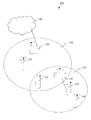
図1aで表されている詳細な実施形態では、無線分配システム100が記載されている。
In the detailed embodiment depicted in FIG. 1a, a
システム、例えば、Wi−Fi分配システムは、中継器110(例えば、少なくとも1つのWi−Fiインターフェイスを備えたセットトップボックス)と、通信デバイス、とりわけ、ネットワークインターコネクションデバイス130(例えば、ゲートウェイ、他のWi−Fi中継器、又はWi−Fiルーター)と、無線クライアントデバイス120、122、124(例えば、制限なしに、スマートフォン又はタブレットのようなモバイルデバイス)とを有する。それは、例えば、Wi−Fi中継器へ有線インターフェイスを介して接続されている有線クライアントデバイス126を更に有することができる。
A system, eg, a Wi-Fi distribution system, includes a repeater 110 (eg, a set top box with at least one Wi-Fi interface) and a communication device, particularly a network interconnection device 130 (eg, a gateway, other Wi-Fi repeater or Wi-Fi router) and
中継器110は、クライアントとしてネットワークインターコネクションデバイス130と関連付けられ得る。
The
クライアントデバイス120、122は、ネットワークインターコネクションデバイス130のカバレッジエリア132に位置することができる。クライアントデバイスは、中継器110のカバレッジエリア112にも位置することができる(例えば、図1aのクライアントデバイス122、124)。
表されている実施形態では、ゲートウェイ、Wi−Fi中継器及びクライアントデバイスは、フレームの送信器を識別するソースアドレスを含むフレームにおいて当該ネットワーク内でデータを交換する(例えば、Wi−Fiフレームについて、このソースアドレスは、Wi−Fiフレームのフィールド“アドレス2”であることができる。)。 In the depicted embodiment, the gateway, Wi-Fi repeater, and client device exchange data within the network in a frame that includes a source address that identifies the sender of the frame (eg, for a Wi-Fi frame, This source address can be the field “address 2” of the Wi-Fi frame.)
表されている実施形態では、ネットワークインターコネクションデバイス130は、DHCPサーバとしても働き、WANインターフェイスを介して他のネットワーク140(例えば、インターネットアクセスプロバイダのネットワーク)へ接続され、他の通信インターフェイス、とりわけ、少なくとも1つの第1の周波数、例えば、図1bで表されているように5GHzで動作するWi−Fiアクセスポイント(例えば、参照符号1300のアクセスポイント)のような無線通信インターフェイスを備えているゲートウェイである。
In the illustrated embodiment, the
ゲートウェイ130のDHCPサーバは、インターネットプロトコルを用いてネットワーク140とのインターフェイスの一意的な指定を可能にしながら、IPアドレスを各クライアントデバイスへ割り当てることができる。
The DHCP server of the
Wi−Fi中継器は、この例では、デュアルバンド中継器である。当業者に明らかなように、ここで開示されている技術は、動作周波数の2つよりも多いバンドが利用される場合にも適用可能である。図1bの表されている実施形態において、Wi−Fi中継器110は、異なった通信インターフェイス、とりわけ、異なった周波数で動作する2つの無線インターフェイス:
− 2.4GHzで動作する第1のWi−Fiアクセスポイント1104;
− 5GHzで動作する第2のWi−Fiアクセスポイント1102
を有する。
In this example, the Wi-Fi repeater is a dual-band repeater. As will be apparent to those skilled in the art, the techniques disclosed herein are also applicable when more than two bands of operating frequencies are utilized. In the depicted embodiment of FIG. 1b, the Wi-
A first Wi-
A second Wi-
Have
それらの異なった周波数のうちの少なくとも1つは、ゲートウェイ130のWi−Fiアクセスポイント1300、1302の動作周波数に対応する。
At least one of these different frequencies corresponds to the operating frequency of the Wi-
図1bの表されている実施形態において、Wi−Fi中継器110は、少なくとも1つの有線インターフェイス、例えば、Ethernetインターフェイス1106を更に有する。
In the depicted embodiment of FIG. 1b, the Wi-
中継器110は、ゲートウェイ130のアクセスポイント1300と同じ周波数で動作するWi−Fi中継器110のWi−Fiアクセスポイント1102に伴って生じる無線接続によって、ゲートウェイ130のアクセスポイント1300へ(クライアントとして)接続される。例えば、中継器110の5GHzの第2のアクセスポイント1102は、ゲートウェイ130の5GHzアクセスポイント1300へ接続される。これは、中継器で仮想クライアントを生成することによって達成されてよい。
The
クライアントデバイス124(例えば、タブレット)は、中継器110の第1のWi−Fiアクセスポイント1104(表されている実施形態では、ゲートウェイ130のWi−Fiアクセスポイント1300とは異なる周波数で動作する。)又は中継器110の第2のWi−Fiアクセスポイント1102(表されている実施形態では、ゲートウェイ130のWi−Fiアクセスポイント1300と同じ周波数で動作する。)を用いたWi−Fi中継器110への接続を要求することができる。Ethernetインターフェイス1260を有するクライアントデバイス126も、中継器110のEthernetインターフェイス1106を介して中継器110へリンクされ得る。図1bは、明りょうさのために、簡略化された説明図である。例えば、図1aのクライアントデバイス120、122は表されていない。
Client device 124 (eg, tablet) operates at a first Wi-
図示されている実施形態では、Wi−Fiタイプの無線プロトコルが使用されており、夫々の無線アクセスポイントは、SSID(Service Set Identifier)のような英数字の文字列によって識別される。それはMACアドレスによっても識別され、夫々のアクセスポイントの一意的な識別を保証することを可能にする。MACアドレスは、通信デバイスのEthernetインターフェイスを識別するためにも使用され得る。 In the illustrated embodiment, a Wi-Fi type wireless protocol is used, and each wireless access point is identified by an alphanumeric string such as an SSID (Service Set Identifier). It is also identified by the MAC address, making it possible to guarantee a unique identification of each access point. The MAC address may also be used to identify the Ethernet interface of the communication device.
図2は、特定の実施形態においてWi−Fi中継器110で実施される本開示の中継方法200を示す。
FIG. 2 illustrates a
詳細な実施形態に従って、図1b及び2によって表されているように、中継方法は、中継器110をゲートウェイ130のアクセスポイント1300と関連付けること210を有する。実施形態に応じて、とりわけ、ゲートウェイのアクセスポイントに応じて、この関連付けに関与する中継器のWi−Fiアクセスポイントは異なってよい。幾つかの実施形態において、中継器のただ1つの無線アクセスポイントがゲートウェイのアクセスポイントと関連付けられる。他の実施形態(例えば、不本意のループを回避するために、全域木アルゴリズムのようなアルゴリズムを実施する。)では、中継器の幾つかの無線アクセスポイントがゲートウェイの異なるアクセスポイントと夫々関連付けられ得る。そのような実施形態は、ゲートウェイとともに使用される最良の経路を中継器が動的に選択することを可能にすることができる。
According to a detailed embodiment, as represented by FIGS. 1 b and 2, the relay method comprises associating 210 the
関連付け210は、例えば、中継器及び/又はゲートウェイの起動及び/又は初期化の間に、実行され得る。
The
本開示の方法は、クライアントデバイス124、126によって送信されてその送信器のアドレス(例えば、記載される特定の実施形態において、その送信器124、126のMACアドレス(MAC3、MAC5)1242、1262)を含むフレーム(例えば、DHCP要求)を受信すること220、230を更に有する。
The method of the present disclosure may be transmitted by a
受信されるフレームは、例えば、ゲートウェイへ送信されるべきデータ又は、フレームが中継器の無線インターフェイスを介して受信される場合にアソシエーション要求のような中継器自身あてのデータを含むことができる。 The received frame can include, for example, data to be transmitted to the gateway or data addressed to the repeater itself, such as an association request if the frame is received via the repeater's radio interface.
表されている実施形態において、中継器と関連付けられる送信器からの要求に対応するフレームを(無線インターフェイスを介して)受信する場合220において、方法は、送信器に対応し仮想アドレスを有する仮想クライアントを生成することを有する。 In the illustrated embodiment, when a frame corresponding to a request from a transmitter associated with a repeater is received (via a radio interface) 220, the method corresponds to the transmitter and a virtual client having a virtual address. To generate.
表されている実施形態に従って、仮想クライアントが生成される方法は、ゲートウェイアクセスポイント1300によって使用される送信チャネルの周波数と比べて、受信アクセスポイント(1102、1104)によって使用される送信チャネルの周波数に依存することができる(240)。
In accordance with the illustrated embodiment, the method by which the virtual client is generated is transmitted to the frequency of the transmission channel used by the receiving access point (1102, 1104) compared to the frequency of the transmission channel used by the
中継器110の受信Wi−Fiアクセスポイント1104(よって、デバイス124のアクセスポイント1240)がゲートウェイ130のアクセスポイント1300によって使用されるのとは異なる周波数を使用する場合には、方法は、送信器についての仮想クライアント1108(又はプロキシクライアント)を生成すること250を有する。この生成250は、クライアントデバイス124のMACアドレス1242の値を仮想クライアントの仮想アドレスへ割り当てること252を有する。
If the receiving Wi-
中継器の受信インターフェイスが、中継器110が接続されているゲートウェイ130のアクセスポイント1300によって使用されるのと同じ周波数で動作するWi−Fiアクセスポイント1102である場合には、方法は、送信器についての仮想クライアント(又はプロキシクライアント)を生成すること260を有する。この生成260は、デバイス124の送信アクセスポイント1240のMACアドレス(MAC3)1242を変換すること262を有する。この変換は、送信アクセスポイントのアドレス1242とは異なる変換後アドレスをもたらす。
If the receiving interface of the repeater is a Wi-
生成260は、変換後アドレスの値を仮想クライアントの仮想アドレスへ割り当てること264を更に有する。
The
ゲートウェイへ送信されるべきデータを、送信器のアドレスを含むフレームにおいて受信する場合230において、送信器は、中継器の既に生成されている仮想クライアントに対応してもしなくてもよい(270)。例えば、仮想クライアントは、アソシエーション要求が既に受信されている場合、又は前のフレームが有線インターフェイスを介して既に受信されている場合に、既に生成されていてよい。 If the data to be transmitted to the gateway is received 230 in a frame that includes the address of the transmitter, the transmitter may or may not correspond to the already generated virtual client of the repeater (270). For example, the virtual client may have already been generated if an association request has already been received or if a previous frame has already been received via the wired interface.
表されている実施形態において、データが未知の送信器から有線インターフェイスを介して受信される場合に、方法は、送信器に関連付けられ仮想アドレスを有する仮想クライアント1110を生成すること280を有する。この生成280は、クライアントデバイス126の有線インターフェイスのMACアドレス1262の値を仮想クライアントの仮想アドレスへ割り当てること282を有する。
In the illustrated embodiment, the method comprises generating 280 a
仮想クライアントが生成されると(270)、あるいは、送信器が既に生成されている(すなわち、既知の)仮想クライアントに対応する場合に、方法は、受信されたデータを、仮想クライアントのおかげで、中継器110が接続されているゲートウェイ130のアクセスポイント1300へ送信すること290を更に有する。
When the virtual client is generated (270), or if the transmitter corresponds to a virtual client that has already been generated (ie, known), the method can receive the received data, thanks to the virtual client, It further includes a
表されている実施形態において、受信フレームに含まれるデータは、そのソースアドレスフィールドにおいて仮想クライアントのMACアドレスを含むヘッダを有するWi−Fiフレームにおいて送信290される。 In the illustrated embodiment, the data contained in the received frame is transmitted 290 in a Wi-Fi frame having a header that includes the virtual client's MAC address in its source address field.
ゲートウェイへ送信されるデータがDHCP要求である特定の場合において、ゲートウェイ130(DHCPサーバとして動作する。)は、仮想クライアントのMACアドレスに従って帰属されるIPアドレスを含むACKメッセージにより応答する。 In the specific case where the data sent to the gateway is a DHCP request, the gateway 130 (acting as a DHCP server) responds with an ACK message containing the IP address attributed according to the virtual client's MAC address.
もっと正確に言えば、Wi−Fiクライアント124が、ゲートウェイ130が仮想クライアント1108からDHCP要求を既に受け取っているときに中継器110からゲートウェイ130へローミングし、DHCP要求がゲートウェイ130によって直接に受信されるようにする場合に、要求は、クライアントデバイス124のMACアドレスMAC3 1242を含む。
More precisely, the Wi-
表されている実施形態に従って、クライアントデバイス124が、ゲートウェイとは異なる周波数で動作する無線デバイスである場合に、仮想クライアント1108は、クライアントデバイス124のMACアドレス1242を割り当てられる。
In accordance with the illustrated embodiment, if the
クライアントデバイス124のMACアドレス1242が、ゲートウェイ130(サーバDHCPとして動作する。)から既に知られている仮想クライアントデバイス1108と同じMACアドレス1242である場合に、ゲートウェイのDHCPモジュールは、同じIPアドレス(以前に仮想クライアントデバイスに帰属されたもの)をクライアントデバイス124へ割り当てる。
If the
このように、幾つかのIP接続がクライアントデバイス124のローミングの時点で既に開始されていた場合に、それらは(アドレス変換アルゴリズムが適用される場合のように)ローミングによって途絶されない。
Thus, if some IP connections have already been initiated at the time of
クライアントデバイス124がゲートウェイ130へ直接に接続され、中継器110のカバレッジエリアへローミングし、中継器がクライアントデバイスMACソースアドレスを仮想クライアント1108へ割り当てる場合に、ゲートウェイは、クライアントデバイスに帰属されているのと同じIPアドレスを仮想クライアントに帰属させる。このように、クライアントデバイスのIP接続の途絶はいずれにしても生じない。このことは、クライアントデバイスが、移動されている間、異なるアクセスポイントの近傍にあるモバイル端末である場合に、特に有用である。
When the
上記の実施形態の幾つかにおいて、中継器の存在は、“IPアドレス”レベルにおいて、ゲートウェイとクライアントデバイスとの間のやりとりにとってトランスペアレントである。 In some of the above embodiments, the presence of the repeater is transparent to the interaction between the gateway and the client device at the “IP address” level.
図3は、図1a及び1bにおいて表されている中継器110のような通信ネットワークデバイス30の構造を記載する。このデバイスは、Wi−Fi中継器であることができる。
FIG. 3 describes the structure of a
図3の特定の実施形態において、中継器30は、タイマ信号も搬送することができるデータ及びアドレスバス300を介して結合されている次のデバイスを有することができる:
− マイクロプロセッサ31(又はCPU);
− グラフィクスカード32(実施形態において、カードは任意であってよい。);
− 少なくとも1つの入力/出力モジュール34(例えば、キーボード、マウス、LED、など);
− ROM(すなわち、Read only Memory)35;
− RAM(すなわち、Random Access Memory)36;
− 第1の周波数での(とりわけWi−Fi又はBluetoothタイプの)無線接続を介したデータの受信及び/又は送信のために構成された第1の通信インターフェイス371;
− (とりわけWi−Fi又はBluetoothタイプの)無線接続を介したデータの受信及び/又は送信のために構成された第2の通信インターフェイス372;
− 有線通信インターフェイス38;
− 電源39。
In the particular embodiment of FIG. 3, the
A microprocessor 31 (or CPU);
A graphics card 32 (in the embodiment, the card may be arbitrary);
At least one input / output module 34 (eg keyboard, mouse, LED, etc.);
-ROM (ie Read only Memory) 35;
-RAM (ie Random Access Memory) 36;
A
A
A
A
幾つかの実施形態において、中継器30は、専用のバス330によってグラフィクスカード32へ直接に接続されているディスプレイモジュール33、例えば、スクリーンを更に有するか、又はそれへ接続され得る。変形例において、ディスプレイは、電子デバイス30の外部にあることができる。幾つかの実施形態において、中継器30は、無線インターフェイスのおかげで、ディスプレイ33と通信することができる。他の実施形態では、中継器30は、表示信号を伝送するケーブルのような有線インターフェイスのおかげで、ディスプレイと通信することができる。中継器30は、LCD又はプラズマスクリーン又はビデオプロジェクタのような外部のディスプレイ装置へ表示信号を送信するよう構成されているコネクタ(図示せず。)又は送信モジュールを有することができる。
In some embodiments, the
記載されているメモリの夫々は、少なくとも1つのレジスタ、すなわち、低容量(わずかのバイナリデータ)又は高容量(プログラム全体の又は計算若しくは表示されるべきデータを表すデータの全て若しくは部分の記憶が可能)のメモリ領域を有することができる。 Each of the described memories can store at least one register, ie, a low capacity (slight binary data) or a high capacity (entire program or all or part of the data representing the data to be calculated or displayed ) Memory area.
中継器が電源を入れられる場合に、マイクロプロセッサ31は、RAM36のレジスタにおけるプログラム命令、特に、ここで記載される再送方法の少なくとも1つの実施形態を実行するのに必要なプロセスをロードし、プログラム命令を実行する。
When the repeater is powered on, the
変形例に従って、中継器30は幾つかのマイクロプロセッサを有する。
According to a variant, the
他の変形例に従って、電源39は、中継器30の外部にある。
According to another variant, the
図3に表されている特定の実施形態では、マイクロプロセッサ31は、第2の通信インターフェイス372又は有線インターフェイス38を介して少なくとも第1のフレームにおいて受信されたデータを、該データを少なくとも1つの第2のフレームにおいて第1の無線インターフェイス371を介して転送することによって中継するよう構成され得る。
In the particular embodiment represented in FIG. 3, the
本開示の実施形態に従って:
− 第2のインターフェイスが、第1の周波数とは異なる周波数で動作する無線インターフェイス372、又は第1のインターフェイスの通信プロトコルとは異なる通信プロトコルを用いる通信インターフェイス38である場合に、第2のフレームは、第1のフレームの送信器のアドレスであるソースアドレスを含み;
− 第2のインターフェイスが、第1の周波数で動作する無線インターフェイス372である場合に、第2のフレームは、第1のフレームの送信器のアドレスとは異なるソースアドレスを含む。
According to embodiments of the present disclosure:
If the second interface is a
If the second interface is a
通信ネットワークデバイス30は、特に、無線デバイスを更に有するシステムに属することができ、マイクロプロセッサ31は、第1の無線インターフェイスを無線デバイスと関連付けるよう構成され得る。
The
本開示は、Wi−Fi分配システムに関して記載されてきた。 The present disclosure has been described with respect to a Wi-Fi distribution system.
当然、当業者に明らかなように、本開示は、他のネットワークプロトコル、特に、Wi−Fi、WiMAX(登録商標)又はBluetoothプロトコルのような、フレームの確認応答を備えたネットワークプロトコルを用いる無線分配システムにおいても適用されてよい。 Of course, as will be apparent to those skilled in the art, the present disclosure provides for wireless distribution using other network protocols, particularly network protocols with frame acknowledgment, such as Wi-Fi, WiMAX® or Bluetooth protocols. It may also be applied in the system.
30 通信ネットワークデバイス
31 マイクロプロセッサ(又はCPU)
38 有線通信インターフェイス
100 無線分配システム
110 中継器
120,122,124 無線クライアントデバイス
126 有線クライアントデバイス
130 ネットワークインターコネクションデバイス
112,132 カバレッジエリア
140 他のネットワーク
371 第1の通信インターフェイス
372 第2の通信インターフェイス
1102,1104 中継器の無線インターフェイス
1106 中継器の有線インターフェイス
1108,1100 仮想クライアント
1242,1262 MACアドレス
1300,1302 ゲートウェイの無線インターフェイス
30
38
Claims (15)
前記第2の通信インターフェイスが、前記第1の周波数とは異なる周波数で動作する無線インターフェイス、又は前記第1の通信インターフェイスの通信プロトコルとは異なる通信プロトコルを用いる通信インターフェイスである場合に、前記第2のフレームは、前記第1のフレームの送信器のアドレスであるソースアドレスを含み、
前記第2の通信インターフェイスが、前記第1の周波数で動作する無線インターフェイスである場合に、前記第2のフレームは、前記第1のフレームの前記送信器のアドレスとは異なるソースアドレスを含む、
方法。 A method implemented in a communication network device having a plurality of communication interfaces, wherein a first communication interface of the communication interfaces is a wireless interface operating at a first frequency, the first of the plurality of communication interfaces In a method of relaying data received in at least one first frame via two communication interfaces by transferring the data via the first communication interface in at least one second frame,
When the second communication interface is a radio interface operating at a frequency different from the first frequency, or a communication interface using a communication protocol different from the communication protocol of the first communication interface, the second communication interface Frame includes a source address that is an address of the transmitter of the first frame,
When the second communication interface is a radio interface operating at the first frequency, the second frame includes a source address different from the address of the transmitter of the first frame;
Method.
前記第2の通信インターフェイスを介して前記第1のフレームの前記送信器からアソシエーション要求を受信するステップと、
前記送信器のアドレスとは異なる仮想アドレスによって識別される前記通信ネットワークデバイス内の仮想クライアントを生成するステップと
を有する請求項1に記載の方法。 When the second communication interface is a radio interface operating at the first frequency before receiving the first frame,
Receiving an association request from the transmitter of the first frame via the second communication interface;
Creating a virtual client in the communication network device identified by a virtual address different from the address of the transmitter.
前記第1の通信インターフェイスを介して前記第1のフレームの前記送信器からアソシエーション要求を受信するステップと、
前記送信器のアドレスの値を割り当てられている仮想アドレスによって識別される前記通信ネットワークデバイス内の仮想クライアントを生成するステップと
を有する請求項1又は2に記載の方法。 Prior to receiving the first frame, the second communication interface operates at a frequency different from the first frequency or uses a communication protocol different from the communication protocol of the first communication interface. If it is an interface,
Receiving an association request from the transmitter of the first frame via the first communication interface;
Generating a virtual client in the communication network device identified by a virtual address that is assigned a value of the sender's address.
を有する請求項1乃至3のうちいずれか一項に記載の方法。 4. When the second communication interface is a wired interface, the method includes: generating a virtual client identified by a virtual address assigned a transmitter address value of the first frame. The method as described in any one of these.
請求項2乃至4のうちいずれか一項に記載の方法。 The source address of the second frame is the virtual address of the virtual client;
5. A method according to any one of claims 2 to 4.
請求項1乃至5のうちいずれか一項に記載の方法。 The first frame and / or the second frame is an Ethernet frame.
6. A method according to any one of claims 1-5.
前記複数の通信インターフェイスのうちの第2の通信インターフェイスを介して少なくとも1つの第1のフレームにおいて受信されるデータを、該データを少なくとも1つの第2のフレームにおいて前記第1の通信インターフェイスを介して転送することによって中継するよう構成される少なくとも1つのプロセッサと
を有し、
前記第2の通信インターフェイスが、前記第1の周波数とは異なる周波数で動作する無線インターフェイス、又は前記第1の通信インターフェイスの通信プロトコルとは異なる通信プロトコルを用いる通信インターフェイスである場合に、前記第2のフレームは、前記第1のフレームの送信器のアドレスであるソースアドレスを含み、
前記第2の通信インターフェイスが、前記第1の周波数で動作する無線インターフェイスである場合に、前記第2のフレームは、前記第1のフレームの前記送信器のアドレスとは異なるソースアドレスを含む、
通信ネットワークデバイス。 A plurality of communication interfaces, wherein a first communication interface of the plurality of communication interfaces is a wireless interface operating at a first frequency;
Data received in at least one first frame via a second communication interface of the plurality of communication interfaces is transferred to the data via the first communication interface in at least one second frame. And at least one processor configured to relay by forwarding,
When the second communication interface is a radio interface operating at a frequency different from the first frequency, or a communication interface using a communication protocol different from the communication protocol of the first communication interface, the second communication interface Frame includes a source address that is an address of the transmitter of the first frame,
When the second communication interface is a radio interface operating at the first frequency, the second frame includes a source address different from the address of the transmitter of the first frame;
Communication network device.
前記第2の通信インターフェイスを介して前記第1のフレームの前記送信器からアソシエーション要求を受信し、
前記送信器のアドレスとは異なる仮想アドレスによって識別される当該通信ネットワークデバイス内の仮想クライアントを生成する
よう構成される、請求項7に記載の通信ネットワークデバイス。 The at least one processor, when the second communication interface is a radio interface operating at the first frequency prior to receiving the first frame;
Receiving an association request from the transmitter of the first frame via the second communication interface;
The communication network device of claim 7, configured to generate a virtual client in the communication network device identified by a virtual address different from the address of the transmitter.
前記第1の通信インターフェイスを介して前記第1のフレームの前記送信器からアソシエーション要求を受信し、
前記送信器のアドレスの値を割り当てられている仮想アドレスによって識別される当該通信ネットワークデバイス内の仮想クライアントを生成する
よう構成される、請求項7又は8に記載の通信ネットワークデバイス。 The at least one processor is configured such that, prior to receiving the first frame, the second communication interface operates at a frequency different from the first frequency, or the communication protocol of the first communication interface Is a wireless interface using a different communication protocol,
Receiving an association request from the transmitter of the first frame via the first communication interface;
9. A communication network device according to claim 7 or 8, configured to generate a virtual client in the communication network device identified by a virtual address that is assigned a value of the transmitter address.
前記第2の通信インターフェイスが、前記第1の周波数とは異なる周波数で動作する無線インターフェイス、又は前記第1の通信インターフェイスの通信プロトコルとは異なる通信プロトコルを用いる通信インターフェイスである場合に、前記第2のフレームは、前記第1のフレームの送信器のアドレスであるソースアドレスを含み、
前記第2の通信インターフェイスが、前記第1の周波数で動作する無線インターフェイスである場合に、前記第2のフレームは、前記第1のフレームの前記送信器のアドレスとは異なるソースアドレスを含む、
システム。 The plurality of communication interfaces, wherein a first communication interface of the plurality of communication interfaces is a wireless interface operating at a first frequency, and at least one through a second communication interface of the plurality of communication interfaces. A communication network comprising: at least one processor configured to relay data received in a first frame by transferring the data in the at least one second frame via the first communication interface; Have a device,
When the second communication interface is a radio interface operating at a frequency different from the first frequency, or a communication interface using a communication protocol different from the communication protocol of the first communication interface, the second communication interface Frame includes a source address that is an address of the transmitter of the first frame,
When the second communication interface is a radio interface operating at the first frequency, the second frame includes a source address different from the address of the transmitter of the first frame;
system.
前記プロセッサは、前記第1の通信インターフェイスを前記無線デバイスと関連付けるよう構成される、
請求項10に記載のシステム。 The system further comprises a wireless device,
The processor is configured to associate the first communication interface with the wireless device;
The system according to claim 10.
ゲートウェイ、
中継器、
ルーター、及び
クライアントデバイス
を含むグループの中から選択された少なくとも1つのデバイスである、
請求項11に記載のシステム。 The wireless device is
gateway,
Repeater,
At least one device selected from the group including routers and client devices;
The system of claim 11.
請求項11又は12に記載のシステム。 The wireless device comprises a DHCP server;
The system according to claim 11 or 12.
複数の通信インターフェイスを有する通信ネットワークデバイスにおいて実行され、前記通信インターフェイスのうちの第1の通信インターフェイスが第1の周波数で動作する無線インターフェイスである方法であって、前記複数の通信インターフェイスのうちの第2の通信インターフェイスを介して少なくとも1つの第1のフレームにおいて受信されるデータを、該データを少なくとも1つの第2のフレームにおいて前記第1の通信インターフェイスを介して転送することによって中継する方法において、
前記第2の通信インターフェイスが、前記第1の周波数とは異なる周波数で動作する無線インターフェイス、又は前記第1の通信インターフェイスの通信プロトコルとは異なる通信プロトコルを用いる通信インターフェイスである場合に、前記第2のフレームは、前記第1のフレームの送信器のアドレスであるソースアドレスを含み、
前記第2の通信インターフェイスが、前記第1の周波数で動作する無線インターフェイスである場合に、前記第2のフレームは、前記第1のフレームの前記送信器のアドレスとは異なるソースアドレスを含む、
方法を実行するプログラムコード命令を有することを特徴とするコンピュータプログラム。 When executed by a computer,
A method implemented in a communication network device having a plurality of communication interfaces, wherein a first communication interface of the communication interfaces is a wireless interface operating at a first frequency, the first of the plurality of communication interfaces In a method of relaying data received in at least one first frame via two communication interfaces by transferring the data via the first communication interface in at least one second frame,
When the second communication interface is a radio interface operating at a frequency different from the first frequency, or a communication interface using a communication protocol different from the communication protocol of the first communication interface, the second communication interface Frame includes a source address that is an address of the transmitter of the first frame,
When the second communication interface is a radio interface operating at the first frequency, the second frame includes a source address different from the address of the transmitter of the first frame;
A computer program comprising program code instructions for performing the method.
前記ソフトウェアプログラムは、該ソフトウェアプログラムがコンピュータによって実行される場合に、
複数の通信インターフェイスを有する通信ネットワークデバイスにおいて実行され、前記通信インターフェイスのうちの第1の通信インターフェイスが第1の周波数で動作する無線インターフェイスである方法であって、前記複数の通信インターフェイスのうちの第2の通信インターフェイスを介して少なくとも1つの第1のフレームにおいて受信されるデータを、該データを少なくとも1つの第2のフレームにおいて前記第1の通信インターフェイスを介して転送することによって中継する方法において、
前記第2の通信インターフェイスが、前記第1の周波数とは異なる周波数で動作する無線インターフェイス、又は前記第1の通信インターフェイスの通信プロトコルとは異なる通信プロトコルを用いる通信インターフェイスである場合に、前記第2のフレームは、前記第1のフレームの送信器のアドレスであるソースアドレスを含み、
前記第2の通信インターフェイスが、前記第1の周波数で動作する無線インターフェイスである場合に、前記第2のフレームは、前記第1のフレームの前記送信器のアドレスとは異なるソースアドレスを含む、
方法を実行するプログラムコード命令を有する、
ことを特徴とするコンピュータ可読記憶媒体。 A computer readable storage medium carrying a software program,
The software program is when the software program is executed by a computer,
A method implemented in a communication network device having a plurality of communication interfaces, wherein a first communication interface of the communication interfaces is a wireless interface operating at a first frequency, the first of the plurality of communication interfaces In a method of relaying data received in at least one first frame via two communication interfaces by transferring the data via the first communication interface in at least one second frame,
When the second communication interface is a radio interface operating at a frequency different from the first frequency, or a communication interface using a communication protocol different from the communication protocol of the first communication interface, the second communication interface Frame includes a source address that is an address of the transmitter of the first frame,
When the second communication interface is a radio interface operating at the first frequency, the second frame includes a source address different from the address of the transmitter of the first frame;
Having program code instructions to perform the method,
A computer-readable storage medium.
Applications Claiming Priority (2)
| Application Number | Priority Date | Filing Date | Title |
|---|---|---|---|
| EP15305625.4A EP3086617A1 (en) | 2015-04-23 | 2015-04-23 | Repeating method and corresponding communication network device, system, computer readable program product and computer readable storage medium |
| EP15305625.4 | 2015-04-23 |
Publications (3)
| Publication Number | Publication Date |
|---|---|
| JP2016208513A true JP2016208513A (en) | 2016-12-08 |
| JP2016208513A5 JP2016208513A5 (en) | 2019-05-30 |
| JP6693799B2 JP6693799B2 (en) | 2020-05-13 |
Family
ID=53175373
Family Applications (1)
| Application Number | Title | Priority Date | Filing Date |
|---|---|---|---|
| JP2016084967A Expired - Fee Related JP6693799B2 (en) | 2015-04-23 | 2016-04-21 | Relay method and corresponding communication network device, system, computer program and computer-readable storage medium |
Country Status (6)
| Country | Link |
|---|---|
| US (1) | US20160315687A1 (en) |
| EP (2) | EP3086617A1 (en) |
| JP (1) | JP6693799B2 (en) |
| KR (1) | KR20160126892A (en) |
| CN (1) | CN106068039A (en) |
| TW (1) | TW201639337A (en) |
Families Citing this family (5)
| Publication number | Priority date | Publication date | Assignee | Title |
|---|---|---|---|---|
| US10652713B2 (en) | 2017-02-22 | 2020-05-12 | Futurewei Technologies, Inc. | Method of application data switching between a device in a wireless PAN mesh network and a virtual ethernet interface |
| US10581673B2 (en) * | 2017-03-08 | 2020-03-03 | Futurewei Technologies, Inc. | Abstracting wireless device to virtual Ethernet interface |
| CN116318597A (en) * | 2018-08-29 | 2023-06-23 | 华为技术有限公司 | Frame transmission method and device |
| US10932157B2 (en) * | 2018-12-19 | 2021-02-23 | Hewlett Packard Enterprise Development Lp | Intelligent link aggregation |
| CN114020651B (en) * | 2022-01-06 | 2022-05-27 | 深圳市明源云科技有限公司 | Interface address based duplicate removal method, device, equipment and readable storage medium |
Family Cites Families (9)
| Publication number | Priority date | Publication date | Assignee | Title |
|---|---|---|---|---|
| JP3619411B2 (en) * | 1999-12-03 | 2005-02-09 | 富士通株式会社 | Packet relay device |
| US6968153B1 (en) * | 2002-03-13 | 2005-11-22 | Nokia Corporation | Apparatus, method and system for a Bluetooth repeater |
| CA2486758A1 (en) * | 2002-06-21 | 2003-12-31 | Widefi, Inc. | Wireless local area network repeater |
| US7230935B2 (en) * | 2002-10-24 | 2007-06-12 | Widefi, Inc. | Physical layer repeater with selective use of higher layer functions based on network operating conditions |
| CN1720755B (en) * | 2002-12-16 | 2010-05-05 | 高通股份有限公司 | Improved wireless network repeater and operation method thereof |
| CN101009932B (en) * | 2006-12-30 | 2010-05-19 | 华为技术有限公司 | A method, system and device for the service switching between the multi-mode networks |
| CN101026591B (en) * | 2007-04-13 | 2010-11-03 | 杭州华三通信技术有限公司 | Network address conflict user inter-access method and route repeating device |
| CN105188061B (en) * | 2011-12-23 | 2017-04-12 | 华为终端有限公司 | Relaying method for wireless relay device and wireless relay device |
| US9961719B2 (en) * | 2013-03-11 | 2018-05-01 | Zte Corporation | Integrated relay in wireless communication networks |
-
2015
- 2015-04-23 EP EP15305625.4A patent/EP3086617A1/en not_active Withdrawn
-
2016
- 2016-04-14 TW TW105111566A patent/TW201639337A/en unknown
- 2016-04-15 EP EP16165507.1A patent/EP3086618B1/en not_active Not-in-force
- 2016-04-20 KR KR1020160048409A patent/KR20160126892A/en unknown
- 2016-04-21 JP JP2016084967A patent/JP6693799B2/en not_active Expired - Fee Related
- 2016-04-22 CN CN201610256608.XA patent/CN106068039A/en active Pending
- 2016-04-22 US US15/135,690 patent/US20160315687A1/en not_active Abandoned
Also Published As
| Publication number | Publication date |
|---|---|
| KR20160126892A (en) | 2016-11-02 |
| CN106068039A (en) | 2016-11-02 |
| TW201639337A (en) | 2016-11-01 |
| JP6693799B2 (en) | 2020-05-13 |
| EP3086618B1 (en) | 2018-06-20 |
| EP3086618A1 (en) | 2016-10-26 |
| US20160315687A1 (en) | 2016-10-27 |
| EP3086617A1 (en) | 2016-10-26 |
Similar Documents
| Publication | Publication Date | Title |
|---|---|---|
| JP6817174B2 (en) | Propagation of data frames across communication networks using incompatible network routing protocols | |
| US9712383B2 (en) | Device abstraction in autonomous wireless local area networks | |
| US9756497B2 (en) | Path switching procedure for device-to-device communication | |
| US9106711B2 (en) | Minimizing mapping and signaling for data path aggregation | |
| US8824480B2 (en) | Method and apparatus for end-host based mobility, multi-homing and multipath protocols | |
| JP6693799B2 (en) | Relay method and corresponding communication network device, system, computer program and computer-readable storage medium | |
| WO2021057217A1 (en) | Communication method, apparatus, device and system, and medium | |
| US9438555B2 (en) | Communicating with a distribution system via an uplink access point | |
| CN111480320B (en) | Source wireless mesh access point WMAP and destination WMAP, and method for forwarding frames through WMAP | |
| US8432877B2 (en) | Routing control method and system | |
| JP6402583B2 (en) | Relay device, relay system, relay method, and program | |
| JP2012054636A (en) | Support apparatus and computer program | |
| US20150120943A1 (en) | Secure mobile access to resources within a private network | |
| KR20140024051A (en) | Communication mechanism for multiple interface network nodes | |
| KR20100059939A (en) | Network allocation | |
| US9602386B2 (en) | Node apparatus, record medium for storing control program, wireless communication system, and method for data communication | |
| CN110351772B (en) | Mapping between wireless links and virtual local area networks | |
| US9473401B2 (en) | Network separation method and network separation device | |
| US20150047009A1 (en) | Access control method, access control system and access control device | |
| KR20190125438A (en) | Data routing method and apparatus | |
| WO2015096734A1 (en) | Downlink transmission method for service data, and packet data gateway | |
| JP4996514B2 (en) | Network system and message transfer method | |
| US8634429B2 (en) | Communication system and method | |
| CN106789529B (en) | Method and terminal for implementing OVERLAY network | |
| WO2015055103A1 (en) | Method and apparatus for obtaining connection information of configuration point |
Legal Events
| Date | Code | Title | Description |
|---|---|---|---|
| RD03 | Notification of appointment of power of attorney |
Free format text: JAPANESE INTERMEDIATE CODE: A7423 Effective date: 20181220 |
|
| RD04 | Notification of resignation of power of attorney |
Free format text: JAPANESE INTERMEDIATE CODE: A7424 Effective date: 20181227 |
|
| A521 | Request for written amendment filed |
Free format text: JAPANESE INTERMEDIATE CODE: A523 Effective date: 20190410 |
|
| A621 | Written request for application examination |
Free format text: JAPANESE INTERMEDIATE CODE: A621 Effective date: 20190410 |
|
| A711 | Notification of change in applicant |
Free format text: JAPANESE INTERMEDIATE CODE: A711 Effective date: 20191111 |
|
| A977 | Report on retrieval |
Free format text: JAPANESE INTERMEDIATE CODE: A971007 Effective date: 20200214 |
|
| TRDD | Decision of grant or rejection written | ||
| A01 | Written decision to grant a patent or to grant a registration (utility model) |
Free format text: JAPANESE INTERMEDIATE CODE: A01 Effective date: 20200401 |
|
| A61 | First payment of annual fees (during grant procedure) |
Free format text: JAPANESE INTERMEDIATE CODE: A61 Effective date: 20200416 |
|
| R150 | Certificate of patent or registration of utility model |
Ref document number: 6693799 Country of ref document: JP Free format text: JAPANESE INTERMEDIATE CODE: R150 |
|
| LAPS | Cancellation because of no payment of annual fees |