JP2016205391A - Process of manufacture of vacuum pump member, vacuum pump member, and vacuum pump - Google Patents
Process of manufacture of vacuum pump member, vacuum pump member, and vacuum pump Download PDFInfo
- Publication number
- JP2016205391A JP2016205391A JP2016083604A JP2016083604A JP2016205391A JP 2016205391 A JP2016205391 A JP 2016205391A JP 2016083604 A JP2016083604 A JP 2016083604A JP 2016083604 A JP2016083604 A JP 2016083604A JP 2016205391 A JP2016205391 A JP 2016205391A
- Authority
- JP
- Japan
- Prior art keywords
- pump
- vacuum pump
- rotor
- stator
- ring
- Prior art date
- Legal status (The legal status is an assumption and is not a legal conclusion. Google has not performed a legal analysis and makes no representation as to the accuracy of the status listed.)
- Pending
Links
Images


Classifications
-
- B—PERFORMING OPERATIONS; TRANSPORTING
- B23—MACHINE TOOLS; METAL-WORKING NOT OTHERWISE PROVIDED FOR
- B23P—METAL-WORKING NOT OTHERWISE PROVIDED FOR; COMBINED OPERATIONS; UNIVERSAL MACHINE TOOLS
- B23P15/00—Making specific metal objects by operations not covered by a single other subclass or a group in this subclass
- B23P15/24—Making specific metal objects by operations not covered by a single other subclass or a group in this subclass dies
- B23P15/246—Laminated dies
-
- F—MECHANICAL ENGINEERING; LIGHTING; HEATING; WEAPONS; BLASTING
- F04—POSITIVE - DISPLACEMENT MACHINES FOR LIQUIDS; PUMPS FOR LIQUIDS OR ELASTIC FLUIDS
- F04D—NON-POSITIVE-DISPLACEMENT PUMPS
- F04D29/00—Details, component parts, or accessories
- F04D29/02—Selection of particular materials
- F04D29/023—Selection of particular materials especially adapted for elastic fluid pumps
-
- B—PERFORMING OPERATIONS; TRANSPORTING
- B33—ADDITIVE MANUFACTURING TECHNOLOGY
- B33Y—ADDITIVE MANUFACTURING, i.e. MANUFACTURING OF THREE-DIMENSIONAL [3-D] OBJECTS BY ADDITIVE DEPOSITION, ADDITIVE AGGLOMERATION OR ADDITIVE LAYERING, e.g. BY 3-D PRINTING, STEREOLITHOGRAPHY OR SELECTIVE LASER SINTERING
- B33Y80/00—Products made by additive manufacturing
-
- F—MECHANICAL ENGINEERING; LIGHTING; HEATING; WEAPONS; BLASTING
- F04—POSITIVE - DISPLACEMENT MACHINES FOR LIQUIDS; PUMPS FOR LIQUIDS OR ELASTIC FLUIDS
- F04C—ROTARY-PISTON, OR OSCILLATING-PISTON, POSITIVE-DISPLACEMENT MACHINES FOR LIQUIDS; ROTARY-PISTON, OR OSCILLATING-PISTON, POSITIVE-DISPLACEMENT PUMPS
- F04C25/00—Adaptations of pumps for special use of pumps for elastic fluids
- F04C25/02—Adaptations of pumps for special use of pumps for elastic fluids for producing high vacuum
-
- F—MECHANICAL ENGINEERING; LIGHTING; HEATING; WEAPONS; BLASTING
- F04—POSITIVE - DISPLACEMENT MACHINES FOR LIQUIDS; PUMPS FOR LIQUIDS OR ELASTIC FLUIDS
- F04D—NON-POSITIVE-DISPLACEMENT PUMPS
- F04D19/00—Axial-flow pumps
- F04D19/02—Multi-stage pumps
- F04D19/04—Multi-stage pumps specially adapted to the production of a high vacuum, e.g. molecular pumps
- F04D19/042—Turbomolecular vacuum pumps
-
- F—MECHANICAL ENGINEERING; LIGHTING; HEATING; WEAPONS; BLASTING
- F04—POSITIVE - DISPLACEMENT MACHINES FOR LIQUIDS; PUMPS FOR LIQUIDS OR ELASTIC FLUIDS
- F04D—NON-POSITIVE-DISPLACEMENT PUMPS
- F04D29/00—Details, component parts, or accessories
- F04D29/26—Rotors specially for elastic fluids
- F04D29/32—Rotors specially for elastic fluids for axial flow pumps
- F04D29/321—Rotors specially for elastic fluids for axial flow pumps for axial flow compressors
-
- B—PERFORMING OPERATIONS; TRANSPORTING
- B22—CASTING; POWDER METALLURGY
- B22F—WORKING METALLIC POWDER; MANUFACTURE OF ARTICLES FROM METALLIC POWDER; MAKING METALLIC POWDER; APPARATUS OR DEVICES SPECIALLY ADAPTED FOR METALLIC POWDER
- B22F10/00—Additive manufacturing of workpieces or articles from metallic powder
- B22F10/10—Formation of a green body
- B22F10/12—Formation of a green body by photopolymerisation, e.g. stereolithography [SLA] or digital light processing [DLP]
-
- B—PERFORMING OPERATIONS; TRANSPORTING
- B22—CASTING; POWDER METALLURGY
- B22F—WORKING METALLIC POWDER; MANUFACTURE OF ARTICLES FROM METALLIC POWDER; MAKING METALLIC POWDER; APPARATUS OR DEVICES SPECIALLY ADAPTED FOR METALLIC POWDER
- B22F10/00—Additive manufacturing of workpieces or articles from metallic powder
- B22F10/10—Formation of a green body
- B22F10/18—Formation of a green body by mixing binder with metal in filament form, e.g. fused filament fabrication [FFF]
-
- B—PERFORMING OPERATIONS; TRANSPORTING
- B22—CASTING; POWDER METALLURGY
- B22F—WORKING METALLIC POWDER; MANUFACTURE OF ARTICLES FROM METALLIC POWDER; MAKING METALLIC POWDER; APPARATUS OR DEVICES SPECIALLY ADAPTED FOR METALLIC POWDER
- B22F10/00—Additive manufacturing of workpieces or articles from metallic powder
- B22F10/20—Direct sintering or melting
- B22F10/28—Powder bed fusion, e.g. selective laser melting [SLM] or electron beam melting [EBM]
-
- C—CHEMISTRY; METALLURGY
- C22—METALLURGY; FERROUS OR NON-FERROUS ALLOYS; TREATMENT OF ALLOYS OR NON-FERROUS METALS
- C22C—ALLOYS
- C22C1/00—Making non-ferrous alloys
- C22C1/04—Making non-ferrous alloys by powder metallurgy
- C22C1/0408—Light metal alloys
- C22C1/0416—Aluminium-based alloys
-
- C—CHEMISTRY; METALLURGY
- C22—METALLURGY; FERROUS OR NON-FERROUS ALLOYS; TREATMENT OF ALLOYS OR NON-FERROUS METALS
- C22C—ALLOYS
- C22C1/00—Making non-ferrous alloys
- C22C1/04—Making non-ferrous alloys by powder metallurgy
- C22C1/045—Alloys based on refractory metals
- C22C1/0458—Alloys based on titanium, zirconium or hafnium
-
- C—CHEMISTRY; METALLURGY
- C22—METALLURGY; FERROUS OR NON-FERROUS ALLOYS; TREATMENT OF ALLOYS OR NON-FERROUS METALS
- C22C—ALLOYS
- C22C1/00—Making non-ferrous alloys
- C22C1/04—Making non-ferrous alloys by powder metallurgy
- C22C1/047—Making non-ferrous alloys by powder metallurgy comprising intermetallic compounds
-
- F—MECHANICAL ENGINEERING; LIGHTING; HEATING; WEAPONS; BLASTING
- F05—INDEXING SCHEMES RELATING TO ENGINES OR PUMPS IN VARIOUS SUBCLASSES OF CLASSES F01-F04
- F05D—INDEXING SCHEME FOR ASPECTS RELATING TO NON-POSITIVE-DISPLACEMENT MACHINES OR ENGINES, GAS-TURBINES OR JET-PROPULSION PLANTS
- F05D2230/00—Manufacture
- F05D2230/20—Manufacture essentially without removing material
- F05D2230/22—Manufacture essentially without removing material by sintering
-
- F—MECHANICAL ENGINEERING; LIGHTING; HEATING; WEAPONS; BLASTING
- F05—INDEXING SCHEMES RELATING TO ENGINES OR PUMPS IN VARIOUS SUBCLASSES OF CLASSES F01-F04
- F05D—INDEXING SCHEME FOR ASPECTS RELATING TO NON-POSITIVE-DISPLACEMENT MACHINES OR ENGINES, GAS-TURBINES OR JET-PROPULSION PLANTS
- F05D2230/00—Manufacture
- F05D2230/30—Manufacture with deposition of material
- F05D2230/31—Layer deposition
-
- Y—GENERAL TAGGING OF NEW TECHNOLOGICAL DEVELOPMENTS; GENERAL TAGGING OF CROSS-SECTIONAL TECHNOLOGIES SPANNING OVER SEVERAL SECTIONS OF THE IPC; TECHNICAL SUBJECTS COVERED BY FORMER USPC CROSS-REFERENCE ART COLLECTIONS [XRACs] AND DIGESTS
- Y02—TECHNOLOGIES OR APPLICATIONS FOR MITIGATION OR ADAPTATION AGAINST CLIMATE CHANGE
- Y02P—CLIMATE CHANGE MITIGATION TECHNOLOGIES IN THE PRODUCTION OR PROCESSING OF GOODS
- Y02P10/00—Technologies related to metal processing
- Y02P10/25—Process efficiency
Abstract
Description
本発明は、真空ポンプ、特にターボ分子ポンプ又はルーツポンプの部材の製造の為の方法、真空ポンプの部材、並びに真空ポンプ、特にターボ分子ポンプ又はルーツポンプに関する。 The present invention relates to a method for the manufacture of a vacuum pump, in particular a turbomolecular pump or a roots pump member, a vacuum pump member, and a vacuum pump, in particular a turbomolecular pump or roots pump.
例えばターボ分子ポンプ又はルーツポンプのような真空ポンプは、複数の部材から成っている。その際、いくつかの部材は複雑な幾何形状を有する可能性があるので、その製造はコスト集中的である。その上、真空ポンプにおけるほとんどの部材は、運転中高い機械的要求にさらされる。部材の機械的な負荷可能性は、主として部材の材料に依存する。真空ポンプにおいては、特にターボ分子ポンプにおいては、特に高負荷部材は通常、アルミニウムから成る。アルミニウムは十分な材料強度を提供する。 A vacuum pump such as a turbomolecular pump or a roots pump is composed of a plurality of members. In doing so, its production is cost intensive since some components may have complex geometries. Moreover, most components in vacuum pumps are exposed to high mechanical requirements during operation. The mechanical loadability of a member depends mainly on the material of the member. In vacuum pumps, especially in turbomolecular pumps, particularly high load members are usually made of aluminum. Aluminum provides sufficient material strength.
真空ポンプの部材の製造の際、特に原材料ブロックから削り出される部材の製造の際、比較的多くの廃棄物が発生する。例えば、ターボ分子ポンプのターボ分子的ポンプ段のローターディスク又はステーターディスクを原材料のブロックから切削過程によって製造する場合、出発原料の90%以上が切削される。 A relatively large amount of waste is generated during the manufacture of vacuum pump components, particularly during the manufacture of components cut from raw material blocks. For example, when a rotor disk or stator disk of a turbo molecular pump stage of a turbo molecular pump is manufactured from a raw material block by a cutting process, 90% or more of the starting material is cut.
よって本発明の課題は、真空ポンプの部材の製造の為の改善された方法を提供することである。当該方法によって、複雑な部材幾何形状も高速で、コスト効率が良く、そして低い材料コストで実現されることが可能である。その上、本発明の課題は、高速かつコスト効率よく製造されることが可能であり、そして好ましくは高い機械的負荷可能性を有する真空ポンプの部材を提供することである。 Accordingly, it is an object of the present invention to provide an improved method for the manufacture of vacuum pump components. With this method, complex member geometries can be realized at high speed, cost-effectively and at low material costs. Furthermore, it is an object of the present invention to provide a vacuum pump component that can be manufactured at high speed and cost-effectively and preferably has a high mechanical load potential.
この課題は、請求項1に記載の特徴を有する方法又は請求項8に記載の特徴を有する部材によって解決される。 This problem is solved by a method having the features of claim 1 or a member having the features of claim 8.
真空ポンプ、特にターボ分子ポンプ又はルーツポンプの部材の製造の為の、発明に係る方法は、部材が生成的な製造方法によって製造されることを含む。 The method according to the invention for the manufacture of components of vacuum pumps, in particular turbomolecular pumps or roots pumps, comprises that the components are manufactured by a generative manufacturing method.
生成的な製造方法とは、体積要素を互いに接合すること、例えば層状に積重ねることによる部材の造形を行うこと、または作りだすことである。従来の製造方法においては、造形は特に旋削又は切削によって行われていた。そのような材料の削剥は、生成的な製造方法においては省略される、又は、後処理の領域の少ない程度に減少されることが可能である。その上、生成的な製造方法においては、鋳造部品におけるように鋳型が必要とされない。 A generative manufacturing method is to form or create a member by joining volume elements together, for example by stacking them in layers. In the conventional manufacturing method, modeling is performed by turning or cutting. Such material ablation can be omitted in the productive manufacturing process or reduced to a lesser extent in the post-processing area. Moreover, in a production process, no mold is required as in cast parts.
生成的な製造方法によって、真空ポンプの、特に複雑な部材も、簡単、迅速、かつ安価で、そして、運転中高い負荷特性(独語:Belastbarkeit)を有する材料の使用の下、製造されることが可能である。生成的な製造方法は、その際、特に、付加的製造(Additive Manufacturing)の為の規格化された符号AMのもとの方法である(VDI−Norm 3404)。 Depending on the production process, particularly complex parts of vacuum pumps can be manufactured in a simple, fast and cheap manner and with the use of materials with high load characteristics (German: Belfastbarkeit) during operation. Is possible. The generative manufacturing method is then in particular a method under the standardized code AM for additive manufacturing (VDI-Norm 3404).
好ましくは、生成的な製造方法は、部材が、ステレオリトグラフ、レーザー溶融、レーザー焼結、選択的レーザー焼結、レイヤーラミネート法、押出成形、熱溶融積層方、積層オブジェクトモデリング、または3Dプリンティングといった方法の少なくとも一つの方法に従い製造されることを含む。上述した製造方法はそれ自体は既知である。 Preferably, the production method is such that the member is stereolithograph, laser melting, laser sintering, selective laser sintering, layer laminating, extrusion, hot melt laminating, laminating object modeling, or 3D printing. In accordance with at least one method. The manufacturing method described above is known per se.
本発明の発展形に従い、部材は、部材の少なくとも一つの計算機内部のデータモデルの基礎に基づいて製造される。計算機内部のデータモデルは、例えば、部材の3D−CAD−体積モデルであることが可能である。これは計算機内部又はコンピューター内部にバーチャルに作りだされる。データモデルは、ユーザーが部材を、その全ての特性に関して観察すること、回転させること、着色すること、及び他の操作を行うことを可能とする。しかし例えば部材の物理的なテストは、不可能である。 In accordance with a development of the invention, the member is manufactured on the basis of a data model within at least one computer of the member. The data model inside the computer can be, for example, a 3D-CAD-volume model of the member. This is created virtually inside the computer or inside the computer. The data model allows the user to observe, rotate, color, and perform other operations on the member with respect to all its properties. However, for example, physical testing of components is not possible.
生成的な製造方法によって、計算機内部のデータモデルから現実の物理的な部材を作りだすために、モデルは数学的に同じ厚さの複数の層にカットされることが可能である。これら層は、その際、例えば約0.1mmの厚さを有し得る。輪郭情報が、生成的な製造装置に供給されることが可能である。これは製作者(ファブリケーター、独語:Fabrikator)とも称される。製造装置は、輪郭情報を使って、其々、部材の一つのディスクを、正確かつ外側の境界を含めて作りだし、そしてこれを、既に前もって作っておいたディスクへと、上から下へと層から層へと部材が生じるように接合する。 The model can be cut into multiple layers of the same thickness mathematically to create a real physical member from a data model inside the computer by means of a generative manufacturing method. These layers can then have a thickness of, for example, about 0.1 mm. The contour information can be supplied to a generative manufacturing device. This is also called a producer (fabricator, German: Fabrikator). The manufacturing device uses the contour information to create a single disc of each part, including the exact outer boundary, and layer this from top to bottom into the disc that was already made in advance. The members are joined to form a layer.
好ましくは、部材は、少なくとも一つの無定形の材料、又は少なくとも一つの形状中立的な材料から、化学的なプロセス、及び/又は物理的なプロセスによって製造される。無定形の材料は、特に流体又は粉状物であることが可能である。形状中立的な材料は、例えばバンド形状またはワイヤー形状の材料であることが可能である。 Preferably, the member is manufactured from at least one amorphous material or from at least one shape neutral material by chemical and / or physical processes. The amorphous material can in particular be a fluid or a powder. The shape neutral material can be, for example, a band or wire shaped material.
本発明の発展形に従い、部材は、少なくとも二つの部材層から、例えば上述したファブリケーターによって構成される。その際、部材層は、磁気的に相前後して、かつ空間的に少なくとも基本的に重なり合って製造されることが可能である。ファブリケーターによって、部材層は、バーチャルなモデルを介して提供される輪郭情報に従い、各層の正確な外側及び内側の境界を含めて、層から層へと下から上に向かって構成されることが可能である。 According to a development of the invention, the member is composed of at least two member layers, for example by the fabricator described above. In this case, the member layers can be manufactured magnetically in series and at least essentially overlapping in space. The fabricator allows the component layers to be constructed from layer to layer from bottom to top, including the exact outer and inner boundaries of each layer, according to the contour information provided through the virtual model. Is possible.
本発明の発展形に従い、部材は少なくとも二つの部材層を有している。これら部材層はラミネート(積層加工、独語:Laminieren)によって互いに接続されることが可能である。その際、部材層は個々に作られる、そして後に互いに接合される又は積層化されることが可能である。よって、二以上の部材層から成る部材を構成するために、いわゆる付加的方法が使用されることが可能である。 According to a development of the invention, the member has at least two member layers. These member layers can be connected to each other by lamination (lamination process, German: Laminieren). In so doing, the component layers can be made individually and later joined or laminated together. Thus, so-called additional methods can be used to construct a member consisting of two or more member layers.
本発明の一つの態様に従い、部材を製造するために少なくとも一つの(一種の)粉状材料が使用される。粉状材料は、物理的、特に熱的または化学的なプロセスによって層ごとに(独語:schichtweise)に固められることが可能である。その際、粉状材料は型内に運ばれそして圧縮されることが可能である。その際、少なくとも近似的に均質(独語:homogen)な材料が形成されることが可能である。 According to one embodiment of the present invention, at least one (a kind) of powdered material is used to produce the member. The powdered material can be consolidated into layers (German) by physical, in particular thermal or chemical processes. The powdered material can then be carried into the mold and compressed. In this case, a material that is at least approximately homogeneous (German) can be formed.
本発明は、真空ポンプ、特にターボ分子ポンプ又はルーツポンプの為の、及び/又は発明に係る方法によって製造された、又は製造可能である部材に関する。その際、部材は粉状材料から構成されていることが可能である。粉状材料からの部材の構成によって、部材は端部輪郭に近く、又は端部輪郭に忠実に、生成的な方法によって製造されることが可能であり、これによって、特に、複雑な部材が安価に、少ない材料コストで、そして少ない廃棄物を発生させつつ製造可能である。 The present invention relates to a component for a vacuum pump, in particular a turbomolecular pump or a roots pump, and / or produced by a method according to the invention. In that case, the member can be composed of a powdery material. Depending on the construction of the component from powdered material, the component can be manufactured in a generative way close to or faithfully to the end profile, which makes it particularly cheap for complex components. Furthermore, it can be manufactured with low material cost and low waste generation.
本発明の一つの態様に従い、粉状材料は、アルミニウム又はチタン又はアルミニウムとチタンの組合せを含んでいる。 According to one embodiment of the invention, the powdered material comprises aluminum or titanium or a combination of aluminum and titanium.
特に、様々な材料コンビネーションが部材中において意図されていることが可能である。部材のある領域が、例えば一つの粉状材料から構成されていることが可能である一方で、他の領域が他の粉状材料から構成されている。部材の第一の領域は、例えば、アルミニウムから、そして部材の第二の領域は、例えばチタンから形成されていることが可能である。その際、両方の領域の間の境界領域内には、金属間結合によるアルミニウム・チタン遷移物(独語:Uebergaenge)が形成されることが可能である。 In particular, various material combinations can be intended in the member. One region of the member can be composed of, for example, one powdered material, while the other region is composed of another powdered material. The first region of the member can be made of, for example, aluminum and the second region of the member can be made of, for example, titanium. In this case, an aluminum-titanium transition material (German: Uebergeenge) can be formed in the boundary region between the two regions.
部材は、様々な粉状材料から形成されていることも可能である。これらは例えばバッファー層を介して組合わせられている。 The member can also be formed from a variety of powdered materials. These are combined through a buffer layer, for example.
好ましくは、部材は少なくとも二つの、特に積層化された部材層から構成されている。これら層は、その際、個々に製造され、そして上述した配置で互いに配置されており、そして特に積層化によって互いに接合されている。 Preferably, the member is composed of at least two, in particular laminated member layers. The layers are then produced individually and are arranged with one another in the arrangement described above and are joined together, in particular by lamination.
本発明の一つの態様に従い、部材は、ターボ分子ポンプのターボ分子的ポンプ段のローターディスク又はステーターディスクである。ローターディスク及び/又はステーターディスクは、比較的複雑な幾何形状を有するので、そのようなディスクは特別有利には、生成的な製造方法によって製造されることが可能である。ローターディスク又はステーターディスクは、好ましくはベースボディ、例えば担持リングを有し、そして該ベースボディに設けられた羽根を有する。ベースボディは、その際、アルミニウムから、そして羽根はチタンから形成されていることが可能であり、そして、生成的な製造方法によって製造されることが可能である。 According to one embodiment of the invention, the member is a rotor disk or stator disk of a turbomolecular pump stage of a turbomolecular pump. Since rotor disks and / or stator disks have a relatively complex geometry, such disks can be produced with particular advantage by generative manufacturing methods. The rotor disk or stator disk preferably has a base body, for example a bearing ring, and has vanes provided on the base body. The base body can then be formed from aluminum and the vanes from titanium and can be manufactured by a generative manufacturing method.
当該部材は、真空ポンプの運転の間、高負荷を受ける部材であることも可能である。これは特に、運転の間高い負荷にさらされる領域内では、高い負荷に耐える材料、例えばチタンのようなものを含む。これに対して、他のより少ない負荷を受ける領域内では、部材は、より低い材料強度を有する材料、例えばアルミニウムのようなものを含む。 The member can also be a member that receives a high load during operation of the vacuum pump. This includes materials that can withstand high loads, such as titanium, particularly in areas that are exposed to high loads during operation. In contrast, in other less loaded areas, the member includes a material having a lower material strength, such as aluminum.
粉末材料は、例えば予合金化されたチタン又はアルミニウムを含む粉状材料であることが可能である。 The powder material can be a powdered material comprising, for example, prealloyed titanium or aluminum.
部材は、リング形状の部材、例えば、ターボ分子ポンプのホルベックポンプ段のホルベックスリーブにおけるSKP−Ringであることが可能である。 The member can be a ring-shaped member, for example, a SKP-Ring in a Holbeck sleeve of a Holbeck pump stage of a turbomolecular pump.
本発明の更なる対象は、上述した説明に従う少なくとも一つの部材を有する真空ポンプ、特にターボ分子ポンプ又はルーツポンプである。部材及びその製造並びに真空ポンプ内におけるその使用に関してここで説明したメリットおよび有利な実施形は、真空ポンプの相応するメリット及び有利な実施形を意味する。 A further subject of the invention is a vacuum pump, in particular a turbomolecular pump or a roots pump, having at least one member according to the above description. The advantages and advantageous embodiments described here with regard to the member and its manufacture and its use in a vacuum pump refer to the corresponding advantages and advantageous embodiments of the vacuum pump.
以下に本発明を添付の図面を参照しつつ例示的に説明する。 The present invention will now be described by way of example with reference to the accompanying drawings.
図1に示された真空ポンプは、インレットフランジ11によって取り囲まれたポンプインレット10と、ポンプアウトレット12と、ポンプインレット10に及ぶプロセスガスをポンプアウトレット12に搬送するための複数のプロセスガスポンプ段を有する。真空ポンプは、ハウジング64と該ハウジング内64内に配置されたローター16を有している。ローターは、ローター軸14を中心に回転可能に支承されたローター軸15を有している。
The vacuum pump shown in FIG. 1 has a
ポンプは、本実施例においてはターボ分子ポンプとして形成されており、そしてポンプ作用を奏する、互いにシリアルに接続された複数のターボ分子的ポンプ段を有する。これらポンプ段は、ローター軸15に固定された半径方向の複数のローターディスク66と、該ローターディスク66の間に配置され、そしてハウジング64内で固定されているステーターディスク68を有している。その際、一つのローターディスク66および隣接する一つのステーターディスク68は、それぞれ一つのターボ分子的ポンプ段を形成する。ステーターディスク68は、スペーサーリング70によって互いに所望の軸方向の間隔に保持されている。
The pump is in this embodiment configured as a turbomolecular pump and has a plurality of turbomolecular pump stages connected in series with each other to perform the pumping action. These pump stages have a plurality of
真空ポンプは、その上、半径方向において入れ子式(独語:ineinander)に配置されており、そして互いにシリアルに接続されているポンプ作用を奏する四つのホルベックポンプ段を有している。ホルベックポンプ段のローターは、ローター軸15と一体に形成されたローターハブ72と、該ローターハブ72に固定され、そしてこれによって担持されているシリンダー側面形状の二つのホルベックロータースリーブ74,76を有している。これらは、回転軸14に同軸に向けられており、そして半径方向に置いて入れ子式に接続されている。更に、シリンダー側面形状の二つのホルベックステータースリーブ78,80が設けられている。これらは、同様に回転軸14に同軸に向けられており、そして半径方向において入れ子式に接続されている。第三のホルベックステータースリーブが、ハウジング64の収容部分132によって形成されている。これは、駆動モーター20の収容及び固定の為に使用される。
In addition, the vacuum pump is arranged radially in a nested manner (German) and has four Holbeck pump stages that act as pumps connected in series with each other. The rotor of the Holbeck pump stage includes a
ホルベックポンプ段のポンプ効果を発する表面は、側面、つまりホルベックロータースリーブ74,76、ホルベックステータースリーブ78,80及び収容部分132の半径方向内側面及び外側面によって形成されている。外側のホルベックステータースリーブ78の半径方向内側面は、半径方向のホルベック間隙82を形成しつつ、外側のホルベックロータースリーブ74の半径方向外側面と向き合っており、そしてこれと第一のホルベックポンプ段を形成する。外側のホルベックロータースリーブ74の半径方向内側面は、半径方向のホルベック間隙84を形成しつつ内側のホルベックステータースリーブ89の半径方向外側面と向き合っており、そしてこれと第二のホルベックポンプ段を形成する。内側のホルベックステータースリーブ80の半径方向内側面は、ホルベック間隙86は、半径方向のホルベック間隙86を形成しつつ内側のホルベックロータースリーブ76の半径方向外側面と向き合っており、そしてこれと第三のホルベックポンプ段を形成する。内側のホルベックロータースリーブ76の半径方向内側面は、半径方向のホルベック間隙87を形成しつつ収容部分132の半径方向外側面と向き合っており、そしてこれと第四のホルベックポンプ段を形成する。
The pumping surface of the Holbeck pump stage is formed by the side surfaces, that is, the radially inner and outer surfaces of the Holbeck rotor sleeves 74, 76, the
ホルベックステータースリーブ78,80と収容部分132の上述したポンプ効果を発する表面は、其々、回転軸14の周りを螺旋形状に軸方向に推移する複数のホルベック溝を有している。他方で、ホルベックロータースリーブ74,76の向き合った表面は、滑らかに形成されており、そしてガスは、真空ポンプの運転中、当該ホルベック溝の中を搬送される。
The above-described pumping surfaces of the
ローター軸15の回転可能な支承の為に、ローラー支承部88がポンプアルトレット12の領域に、そして永久磁石支承部90がポンプインレット10の領域に設けられている。
A
ローラー支承部88の領域には、ローター軸15に円すい形のスプラッシュナット92が、ローラー支承部88の方向に向かって増加する外直径を有し、設けられている。スプラッシュナット92は、作動媒体貯蔵部の少なくとも一つのスキマー(独語:Abstreifer)と滑り接触している。作動媒体貯蔵部は、互いに積層された吸収性の複数のディスク94を有する。これらは、ローラー支承部88の為の作動媒体、例えば潤滑媒体を浸されている。真空ポンプの作動中、作動媒体は、毛細管効果によって作動媒体貯蔵部から、スキマーを介して、回転するスプラッシュナット92へと伝達され、そして遠心力の結果、スプラッシュナット92に沿って、大きくなるスプラッシュナット92の外直径の方向へと、ローラー支承部88に向かって搬送され、そこで例えば潤滑機能を発揮する。ローラー支承部88と作動媒体貯蔵部は、真空ポンプのカバー要素98及び槽形状のインサート96によって囲まれている。
In the region of the
永久磁石支承部は、ローター側の支承半部100とステーター側の支承半部102を有する。これらは、各一つのリング積層部を有する。リング積層部は、軸方向に互いに積層された永久磁石の複数のリング104または106から成る。磁石リング104,106は、半径方向の支承間隙108を形成しつつ互いに向き合っており、その際、ローター側の磁石リング104は、半径方向の外側、そしてステーター側の磁石リング106は半径方向の内側に配置されている。支承間隙108内に存在する磁場は、磁気的反発力を、磁石リング104,106の間に引き起こす。これらは、ローター軸15の半径方向の支承に作用する。
The permanent magnet bearing has a rotor-
ローター側の磁石リング104は、ローター軸のキャリア110に担持されている。このローター軸は、磁石リング104を半径方向外側において取り囲んでいる。ステーター側の磁石リングは、ステーター側のキャリア部分112によって担持されている。このキャリア部分は、磁石リング112を通って延在しており、ハウジング64の半径方向の支柱114に懸架されている。回転軸14に平行に、ローター側の磁石リング104は、一方の方向では、キャリア部分110と連結されたカバー要素116によって、そして他方の方向では、半径方向に突き出したキャリア部分110のショルダー部分によって固定されている。ステーター側の磁石リング106は、回転軸14に平行に、一方の方向では、キャリア部分112と接続された固定リング118によって、そして、固定リング118と磁石リング106の間に設けられたバランス要素120によって、そして他方の方向では、キャリア部分112と接続されたサポートリング122によって固定されている。
The rotor-
磁石支承部の内部には、緊急又は安全用支承部(Not− bzw. Fanglager)124が設けられている。これは、真空ポンプの通常の運転では、非接触で起立しており、ローター16がステーターに対して半径方向に過剰に傾いた際に初めてこれと係合するに至り、そして共に動き、ローター16の為の半径方向のストッパーを形成する。このストッパーは、ローター側の構造がステーター側の構造と衝突するのを防止する。安全用支承部124は、潤滑されていないローラー支承部として形成されており、そしてローター16及び/又はステーターと半径方向の間隙を形成する。この間隙は、安全用支承部124が通常のポンプ運転において係合しないことに作用する。安全用支承部14が係合する半径方向の傾きは、十分大きく寸法決めされているので、安全用支承部124は真空ポンプの通常の運転で係合せず、そして同時に十分小さいのでローター側の構造がステーター側の構造と衝突することを、どんなことがあっても防止する。
An emergency or safety support (Not-bzw. Fanglager) 124 is provided inside the magnet support. In normal operation of the vacuum pump, this stands up in a non-contact manner, and only when the
真空ポンプは、ローター16の回転駆動の為の駆動モーター20を有する。駆動モーター20は、一つのコア38を有し、そして一又は複数の図1には簡略的にのみ表されているコイル42を有するモーターステーター22を有する。これらコイルは、コア38の半径方向内側に設けられるコア38の溝内に固定されている。
The vacuum pump has a
駆動モーター20のアンカー(独語:Anker)が、ローター16によって形成されており、そのローター軸15が、モーターステーター22を貫通して延在している。ローター軸15の、モーターステーター22を貫通して延在する部分には、半径方向外側に、永久磁石装置128が固定されている。モーターステーター22と、ローター16のモーターステーター22を貫通して延在する部分の間には、中間空間24が設けられている。この中間空間は、半径方向のモーター間隙を有する。このモーター間隙を介して、モーターステーター22と永久磁石装置128が駆動トルクの伝達の為に磁気的に影響する。
An anchor (German: Anker) of the
永久磁石装置128は、軸方向において、ローター軸15上にかぶせられた(独語:aufgesteckte)固定スリーブ126によってローター軸15に固定されている。カプセル部130が、永久磁石装置128をその半径方向外側において取り囲んでおり、そしてこれを中間空間24に対してシールしている。
The
モーターステーター22は、ハウジング64内で、ハウジング固定の収容部分132によって固定されている。これは、モーターステーター22を半径方向外側で取り囲み、そしてモーターステーター22を半径方向及び軸方向で支持している。収容部分132は、ローターハブ72とともにモーター室18を画成する。この中に駆動モーター20が収容されている。
The
モーター室18は、中間空間24の一方の側に設けられ、そして内側に位置する第四のホルベックポンプ段によってガスを導くよう接続されたインレット28と、中間空間24の向き合った側に設けられ、そしてポンプアウトレット12とガスを導くよう接続されたアウトレット30を有している。
The
モーターステーター22のコアは、その半径方向外側、図1において左側に示された領域に、空所部34を有する。これは、収容部分132の隣接する領域とともにチャネル32を形成する。このチャネルによって、モーター室18内に搬送されるプロセスガスが、中間空間24を通過し、インレット28からアウトレット30へと搬送される。
The core of the
プロセスガスがポンプインレット10からポンプアウトレット12へと至るガス経路は、図1において矢印26によって見て取れる。プロセスガスは、ポンプインレット10から出発して、まず順番にターボ分子的ポンプ段を通って、そして引き続いて順番に四つのホルベックポンプ段を通って搬送される。第四のホルベックポンプ段から発生するガスは、モーター室18に至り、そしてモーター室18のインレット28からチャネル32を通ってモーター室18のアウトレット30とポンプアウトレット12に搬送される。
The gas path from which process gas leads from the
図1の真空ポンプにおいては、ローター軸15に固定された半径方向のローターディスク66と、ローターディスク66の間に配置され、かつ真空ポンプのハウジング64に固定されているステーターディスク68が、其々対としてターボ分子的ポンプ段を形成する。
In the vacuum pump of FIG. 1, a
図2は、ローターディスク66の上面図を示す。これは、半径方向内側に位置する担持リング136を有している。担持リングには、外側に向かって推移し、かつ担持リング136の周囲方向においてみて互いにオフセットして設けられる複数の羽根134が設けられている。ローターディスク66の担持リング136の半径方向内側面と、ローター軸15の半径方向外側面の間には、しまり嵌め(独語:Querpressverbindung)が生じる。これは、上述した面をお互いに押圧する。押圧は、固定的かつ極めて確実にローターディスク66がローター軸15上にシートすることが保証されているように行われる。
FIG. 2 shows a top view of the
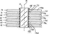
図3は、複数のローターディスク66を有する装置を示す。当該装置は、図2を参照しつつ先に説明したように、ローター軸15上に設けられている。図1を参照しつつ上述したように、軸方向で見て、ローターディスク66はステーターディスク68と交互に交替している。ステーターディスク68のうち、図3には羽根140のみが示されている。これらは、半径方向外側に設けられ、かつ真空ポンプのハウジングによって担持されている担持リング(ステーターディスク68の担持リング)から出発して半径方向内側に向かって延在している。
FIG. 3 shows an apparatus having a plurality of
担持リング136には、軸方向でみて羽根134の上側および下側に各一つの補強リング138が設けられていることが可能である。各補強リング138の半径方向内側面と、各担持リング136の半径方向外側面の間には、ここでもまた、しまり嵌めが形成されていることが可能である。これによって各ローターディスク66のローター軸15に対するシートの強度が向上されることが可能である。
The
各ローターディスク66は、上述したバリエーションにおいては、よって担持リング136(担持リングは、これに設けられた羽根134を有する)から成っている。相応して、各ステーターディスク68は、担持リング(担持リングはこれに設けられた羽根140を有する)から成っている。ローターディスク66又はステーターディスク68は、例えば、発明に従い特に有利に、生成的な製造方法によって製造される、または製造されている部材である。というのは、これによって特に、比較的複雑な羽根134,140の幾何形状が特に簡単に実現されることが可能だからである。生成的な製造方法は、その際、ローターディスク66又はステーターディスク68が、ステレオリトグラフ、レーザー溶融、レーザー焼結、選択的レーザー焼結、層ラミネート方法、押出成形、熱溶融積層法、ラミネートオブジェクトモデリング、または3Dプリンティングの少なくとも一つに従い製造されることを含む。その際、部材66,68は、二以上の部材層から構成されることが可能である。これらは、時期的にみて相次いで、そして空間的にみて重なり合って生成的な製造方法によってつくりだされることが可能である。その際、重なり合った部材層は、積層によってまとめられることが可能である。
Each
部材の製造の為に、好ましくは少なくとも粉状材料が仕様される。特に、担持リング(ローターディスク66の担持リング136参照)の製造の為に、羽根(羽根134および140参照)の製造のためのものと異なる粉状材料が仕様される。例えば担持リングは、アルミニウムから、そして羽根はチタンから生成的な製造方法によって作られることが可能である。担持リングと羽根の間の接続箇所には、その際、金属間化結合(独語:intermetallische Verbindung)によるアルミニウム・チタン・繊維部が形成されることが可能である。
For the production of the component, preferably at least a powdered material is specified. In particular, for the production of the carrier ring (see the
生成的な製造方法によるローターディスク66とステーターディスク68の製造は、例としてのみ見られる。当然、他の部材、特に、複雑な幾何形状を有する部材、及び/又は真空ポンプの運転中に高い負荷にさらされる部材も、生成的な製造方法によって作られることが可能である。
The production of the
図1に表されたターボ分子ポンプの他の真空ポンプの部材も、生成的な製造方法によって作られることが可能である。例えば、上述した方法によってルーツポンプ(独語:Waelzkolbenpumpe)の部材も作られることが可能である。例えば、ルーツポンプのローターが生成的に作られることが可能であり、その際、特にローターにおいて意図されるハチの巣構造が簡単な方法、少ない材料コスト、及び少ない廃棄物で作られることが可能である。 Other vacuum pump components of the turbomolecular pump represented in FIG. 1 can also be made by a generative manufacturing method. For example, a member of a roots pump (German: Waelzkolbenpumpe) can be made by the above-described method. For example, the roots pump rotor can be made generatively, and in particular the honeycomb structure intended in the rotor can be made in a simple way, with less material costs and less waste It is.
10 ポンプインレット
11 インレットフランジ
12 ポンプアウトレット
14 回転軸
15 ローター軸
16 ローター
18 モーター室
20 駆動モーター
22 モーターステーター
24 中間空間
26 矢印、ガス経路
28 インレット
30 アウトレット
32 チャネル
34 空所部
38 コア
42 コイル
64 ハウジング
66 ローターディスク
68 ステーターディスク
70 スペーサーリング
72 ローターハブ
74,76 ホルベックロータースリーブ
78,80 ホルベックステータースリーブ
82,84,86,87 ホルベック間隙
88 ローラー支承部
90 永久磁石支承部
92 スプラッシュナット
94 吸収性のディスク
96 槽形状のインサート
98 カバー要素
100 ローター側の支承半部
102 ステーター側の支承半部
104,106 磁石リング
108 支承間隙
110,112 キャリア部分
114 支柱
116 カバー要素
118 固定リング
120 バランス要素
122 サポートリング
124 安全用支承部
126 固定スリーブ
128 永久磁石装置
130 カプセル部
132 収容部分
134 羽根
136 担持リング
138 補強リング
140 羽根
DESCRIPTION OF
Claims (13)
部材(66,68)が、生成的な製造方法によって作られることを特徴とする方法。 In a process for the manufacture of vacuum pumps, in particular turbomolecular pumps or root pump components (66, 68),
Method characterized in that the members (66, 68) are made by a generative manufacturing method.
部材(66,68)が、粉状材料から構成されることを特徴とする部材。 In a member for a vacuum pump, in particular a turbomolecular pump or a roots pump, and / or manufactured or manufacturable according to the method according to any one of claims 1 to 7,
The member (66, 68) is composed of a powdery material.
Applications Claiming Priority (2)
| Application Number | Priority Date | Filing Date | Title |
|---|---|---|---|
| EP15164361.6A EP3085964B1 (en) | 2015-04-21 | 2015-04-21 | Production of a vacuum pump part by metallic additive manufacturing |
| EP15164361.6 | 2015-04-21 |
Publications (1)
| Publication Number | Publication Date |
|---|---|
| JP2016205391A true JP2016205391A (en) | 2016-12-08 |
Family
ID=52987981
Family Applications (1)
| Application Number | Title | Priority Date | Filing Date |
|---|---|---|---|
| JP2016083604A Pending JP2016205391A (en) | 2015-04-21 | 2016-04-19 | Process of manufacture of vacuum pump member, vacuum pump member, and vacuum pump |
Country Status (3)
| Country | Link |
|---|---|
| EP (1) | EP3085964B1 (en) |
| JP (1) | JP2016205391A (en) |
| CN (1) | CN106064291A (en) |
Cited By (3)
| Publication number | Priority date | Publication date | Assignee | Title |
|---|---|---|---|---|
| CN110270688A (en) * | 2019-07-09 | 2019-09-24 | 南京中科煜宸激光技术有限公司 | Steel mill's heat resistant and wear resistant anticorrosion bearing ring and its compound increasing material manufacturing method |
| WO2023106155A1 (en) * | 2021-12-07 | 2023-06-15 | エドワーズ株式会社 | Vacuum pump, vacuum pump constituent component, and method for producing vacuum pump |
| WO2023136262A1 (en) * | 2022-01-13 | 2023-07-20 | エドワーズ株式会社 | Vacuum pump, rotating body for vacuum pump, and method for manufacturing vacuum pump |
Families Citing this family (9)
| Publication number | Priority date | Publication date | Assignee | Title |
|---|---|---|---|---|
| GB2568066A (en) * | 2017-11-02 | 2019-05-08 | Edwards Ltd | Stator blade unit for a turbomolecular pump |
| GB2570925B (en) | 2018-02-12 | 2021-07-07 | Edwards Ltd | Reinforced vacuum system component |
| GB2574648A (en) * | 2018-06-14 | 2019-12-18 | Edwards Ltd | Pump bearing lubricant supply systems |
| EP3683447B1 (en) * | 2019-12-19 | 2021-11-24 | Pfeiffer Vacuum GmbH | Vacuum pump |
| EP3693610B1 (en) * | 2020-01-27 | 2021-12-22 | Pfeiffer Vacuum Technology AG | Molecular vacuum pump |
| GB2596275A (en) * | 2020-05-20 | 2021-12-29 | Edwards Ltd | Cooling element |
| CN111659884A (en) * | 2020-07-09 | 2020-09-15 | 哈尔滨坤程科技有限公司 | Metal 3D printer |
| EP3786457B1 (en) * | 2020-09-09 | 2022-09-07 | Pfeiffer Vacuum Technology AG | Rotor arrangement for a vacuum pump, vacuum pump and method for manufacturing the same |
| FR3137726A1 (en) * | 2022-07-07 | 2024-01-12 | Pfeiffer Vacuum | Turbomolecular vacuum pump and methods of manufacturing a rotor |
Citations (5)
| Publication number | Priority date | Publication date | Assignee | Title |
|---|---|---|---|---|
| JPS6361799A (en) * | 1986-09-02 | 1988-03-17 | Nippon Soken Inc | Turbo molecular pump |
| JP2005291135A (en) * | 2004-04-01 | 2005-10-20 | Kyocera Corp | Multistage positive-displacement vacuum pump and its manufacturing method |
| WO2013151015A1 (en) * | 2012-04-04 | 2013-10-10 | 株式会社島津製作所 | Vacuum pump |
| JP2014111939A (en) * | 2012-12-04 | 2014-06-19 | Pfeiffer Vacuum Gmbh | Vacuum pump |
| JP2014214745A (en) * | 2013-04-22 | 2014-11-17 | プファイファー・ヴァキューム・ゲーエムベーハー | Stator element for holweck pump stage, vacuum pump with holweck pump stage and method for manufacturing stator element for holweck pump stage |
Family Cites Families (9)
| Publication number | Priority date | Publication date | Assignee | Title |
|---|---|---|---|---|
| JPS5946394A (en) * | 1983-07-13 | 1984-03-15 | Hitachi Ltd | Turbo molecular pump |
| JPS6163385A (en) * | 1984-09-05 | 1986-04-01 | Hitachi Ltd | Manufacture of rotor of turbo-molecular pump |
| JPH04370394A (en) * | 1991-06-19 | 1992-12-22 | Seiko Seiki Co Ltd | Vacuum pump |
| DE10039006A1 (en) * | 2000-08-10 | 2002-02-21 | Leybold Vakuum Gmbh | Two-shaft vacuum pump |
| DE10053663A1 (en) * | 2000-10-28 | 2002-05-08 | Leybold Vakuum Gmbh | Mechanical kinetic vacuum pump with rotor and shaft |
| DE10053664A1 (en) * | 2000-10-28 | 2002-05-08 | Leybold Vakuum Gmbh | Mechanical kinetic vacuum pump |
| JP4395052B2 (en) * | 2004-11-10 | 2010-01-06 | 太陽誘電株式会社 | Drive device |
| GB0511877D0 (en) * | 2005-06-10 | 2005-07-20 | Boc Group Plc | Vacuum pump |
| EP2772329A1 (en) * | 2013-02-28 | 2014-09-03 | Alstom Technology Ltd | Method for manufacturing a hybrid component |
-
2015
- 2015-04-21 EP EP15164361.6A patent/EP3085964B1/en active Active
-
2016
- 2016-04-19 CN CN201610243828.9A patent/CN106064291A/en active Pending
- 2016-04-19 JP JP2016083604A patent/JP2016205391A/en active Pending
Patent Citations (5)
| Publication number | Priority date | Publication date | Assignee | Title |
|---|---|---|---|---|
| JPS6361799A (en) * | 1986-09-02 | 1988-03-17 | Nippon Soken Inc | Turbo molecular pump |
| JP2005291135A (en) * | 2004-04-01 | 2005-10-20 | Kyocera Corp | Multistage positive-displacement vacuum pump and its manufacturing method |
| WO2013151015A1 (en) * | 2012-04-04 | 2013-10-10 | 株式会社島津製作所 | Vacuum pump |
| JP2014111939A (en) * | 2012-12-04 | 2014-06-19 | Pfeiffer Vacuum Gmbh | Vacuum pump |
| JP2014214745A (en) * | 2013-04-22 | 2014-11-17 | プファイファー・ヴァキューム・ゲーエムベーハー | Stator element for holweck pump stage, vacuum pump with holweck pump stage and method for manufacturing stator element for holweck pump stage |
Cited By (4)
| Publication number | Priority date | Publication date | Assignee | Title |
|---|---|---|---|---|
| CN110270688A (en) * | 2019-07-09 | 2019-09-24 | 南京中科煜宸激光技术有限公司 | Steel mill's heat resistant and wear resistant anticorrosion bearing ring and its compound increasing material manufacturing method |
| WO2023106155A1 (en) * | 2021-12-07 | 2023-06-15 | エドワーズ株式会社 | Vacuum pump, vacuum pump constituent component, and method for producing vacuum pump |
| WO2023136262A1 (en) * | 2022-01-13 | 2023-07-20 | エドワーズ株式会社 | Vacuum pump, rotating body for vacuum pump, and method for manufacturing vacuum pump |
| JP7390408B2 (en) | 2022-01-13 | 2023-12-01 | エドワーズ株式会社 | Vacuum pump, rotating body for vacuum pump, and manufacturing method of vacuum pump |
Also Published As
| Publication number | Publication date |
|---|---|
| EP3085964B1 (en) | 2019-12-11 |
| EP3085964A1 (en) | 2016-10-26 |
| CN106064291A (en) | 2016-11-02 |
Similar Documents
| Publication | Publication Date | Title |
|---|---|---|
| JP2016205391A (en) | Process of manufacture of vacuum pump member, vacuum pump member, and vacuum pump | |
| JP5981968B2 (en) | Vacuum pump | |
| JP6154787B2 (en) | Vacuum pump | |
| US20150267543A1 (en) | Monolithic shrouded impeller | |
| JP6447662B2 (en) | Electric motor system and turbo compressor provided with the same | |
| US20140097711A1 (en) | One piece rotor hub/shaft for an electric machine and method | |
| US10946487B2 (en) | Method for producing a turbomachine impeller | |
| CN103958937B (en) | Torque converter | |
| US20180050422A1 (en) | Method for manufacturing compressor components | |
| JP4846230B2 (en) | Bearingless electromagnetic rotating device | |
| JP2019509002A (en) | Integrated motor | |
| JP6017278B2 (en) | High-speed rotor for vacuum pump | |
| WO2014184368A1 (en) | Impeller with backswept circular pipes | |
| CN107147226A (en) | Rotor, motor and correlation technique | |
| CN110214221A (en) | Stator-cap unit green compact | |
| CN102335755A (en) | Large-sized precise direct-driving main shaft structure | |
| CN105697395B (en) | Rotor facility and its manufacturing method for vacuum pump | |
| US11139704B2 (en) | Salient pole rotor with magnetic pole portions, concave portions and cylindrical cover portion with fiber filament | |
| JP6253700B2 (en) | Vacuum pump rotor device | |
| CN106208573A (en) | Axial air gap switched reluctance motor structure | |
| CN105992879A (en) | Fluid dynamic bearing device and motor provided therewith | |
| JP2021515157A (en) | Vacuum pump | |
| JP6166296B2 (en) | Stator disk | |
| JP6351654B2 (en) | Vacuum pump rotor | |
| CN103867290A (en) | Turbocharger embedding an electrical machine with permanent magnets |
Legal Events
| Date | Code | Title | Description |
|---|---|---|---|
| A131 | Notification of reasons for refusal |
Free format text: JAPANESE INTERMEDIATE CODE: A131 Effective date: 20170222 |
|
| A521 | Request for written amendment filed |
Free format text: JAPANESE INTERMEDIATE CODE: A523 Effective date: 20170421 |
|
| A131 | Notification of reasons for refusal |
Free format text: JAPANESE INTERMEDIATE CODE: A131 Effective date: 20170830 |
|
| A601 | Written request for extension of time |
Free format text: JAPANESE INTERMEDIATE CODE: A601 Effective date: 20171124 |
|
| A521 | Request for written amendment filed |
Free format text: JAPANESE INTERMEDIATE CODE: A523 Effective date: 20180126 |
|
| A02 | Decision of refusal |
Free format text: JAPANESE INTERMEDIATE CODE: A02 Effective date: 20180530 |