JP2016202444A - Washing machine - Google Patents
Washing machine Download PDFInfo
- Publication number
- JP2016202444A JP2016202444A JP2015085968A JP2015085968A JP2016202444A JP 2016202444 A JP2016202444 A JP 2016202444A JP 2015085968 A JP2015085968 A JP 2015085968A JP 2015085968 A JP2015085968 A JP 2015085968A JP 2016202444 A JP2016202444 A JP 2016202444A
- Authority
- JP
- Japan
- Prior art keywords
- tub
- fluid balancer
- peripheral surface
- laundry
- washing
- Prior art date
- Legal status (The legal status is an assumption and is not a legal conclusion. Google has not performed a legal analysis and makes no representation as to the accuracy of the status listed.)
- Pending
Links
Images


Abstract
Description
本発明は、洗濯機に関する。 The present invention relates to a washing machine.
近年、地球温暖化防止、つまり地球環境保護のために家電製品の省エネ化が進行しつつある。
そこで、洗濯機では洗濯容量のアップや節水が着目されている。
In recent years, energy saving of household electrical appliances is progressing to prevent global warming, that is, to protect the global environment.
Accordingly, attention has been focused on increasing the washing capacity and saving water in washing machines.
洗濯容量をアップするには、洗濯槽兼脱水槽である内槽および内槽を収容する外槽を大きくすることが考えられる。しかし、家電製品の大型化は住居の床面積に制限がある現状では消費者には受け入れ難い状況にある。
本願に係る文献公知発明として、下記の特許文献1がある。
In order to increase the washing capacity, it is conceivable to enlarge the inner tub that is a washing tub and dewatering tub and the outer tub that accommodates the inner tub. However, the increase in the size of home appliances is unacceptable to consumers in the current situation where there is a limit on the floor area of the house.
The following
そこで、内槽および外槽の外形状の大きさを大きくすることなく、洗濯容量をアップする場合、以下の問題が発生する。
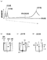
図16は、従来の洗濯機の流体バランサ近傍の縦断面図である。
Therefore, when the washing capacity is increased without increasing the size of the outer shape of the inner tub and the outer tub, the following problems occur.
FIG. 16 is a longitudinal sectional view of the vicinity of a fluid balancer of a conventional washing machine.
脱水運転時、内槽109が高速回転されると、脱水運転時には、洗濯物が入れられる内槽109に振動が発生する。特に、固有振動数での共振振動に際しては、内槽109の振幅が大きくなる。この脱水運転時には、洗濯物が遠心力で内槽109に強く押し当てられる。
When the
そのため、内槽109の振幅が大きい共振時には、内槽109の上部に設けられ高速回転する流体バランサ112と、静止状態の外槽110の上縁部に設けられる外槽カバー114との間の隙間s100に洗濯物iが入り込んだり、噛み込まれる(図17(a)、(b)の洗濯物i1参照)という現象が発生する。なお、図17(a)、(b)は、従来の流体バランサと外槽カバーとの間の隙間に洗濯物が入り込んだ状態を示す斜視図である。
Therefore, at the time of resonance where the amplitude of the
この洗濯物の入り込み現象がひどい場合には、洗濯物が外槽カバー114と流体バランサ112との間の隙間s100に噛み込まれ、噛み込まれた洗濯物i1が破損するという由々しき事態が生じるおそれがある。
そのため、従来、洗濯物の入り込み現象を抑制するため、次の方策が講じられている。
When the phenomenon of entering the laundry is severe, the laundry is caught in the gap s100 between the
Therefore, conventionally, the following measures have been taken in order to suppress the entry phenomenon of laundry.
第1に、洗濯槽の内槽109の高さを高くし、高速回転する内槽109の上部の流体バランサ112と、静止した外槽カバー114との間の隙間s100の寸法s101(図16参照)を小さくし、洗濯物の入り込みを抑制する。
First, the height of the
第2に、流体バランサ112の上縁に、遮断壁となるリング状の上部リブ112r(図16参照)を設け、高速回転する流体バランサ112と静止した外槽カバー114との間の隙間s100への洗濯物の入り込み、噛み込みを抑制する。
Second, a ring-shaped
第3に、流体バランサ112の内周下角部のRを小さくして、洗濯物が当該Rに案内されて、流体バランサ112の上方へ移動することを妨げる。当該Rが大きい場合、洗濯物iは、大きなRに案内されてスムーズに上方に移動し、高速回転する流体バランサ112と静止した外槽カバー114との間の隙間s100に入り込んだり、噛み込まれることに繋がる。
Third, R at the inner peripheral lower corner of the
本発明は上記実状に鑑み、洗濯兼脱水槽の外形を大きくすることなく、洗濯容量を増加でき、脱水運転時の洗濯物の洗濯兼脱水槽と外槽カバーとの間への入り込み、噛み込みを抑制できる洗濯機の提供を目的とする。 In view of the above situation, the present invention can increase the washing capacity without enlarging the outer shape of the washing and dewatering tub, and can enter and bite the laundry between the washing and dewatering tub and the outer tub cover during the dehydration operation. It aims at providing the washing machine which can control.
前記課題を解決するため、本発明の洗濯機は、洗濯物の洗濯兼脱水槽の内槽と、 前記内槽の上部に設けられ、前記内槽の脱水運転時の振動を抑制する内部に流体を有する環状の流体バランサと、洗濯水を溜め、前記内槽を収容する外槽とを備え、前記流体バランサは、その内周面に、脱水運転時に前記内槽が振動して傾いた際に前記内槽側に向いて傾斜する傾斜周面を有している。 In order to solve the above problems, a washing machine of the present invention is provided with an inner tub of a laundry washing and dewatering tub, and an upper part of the inner tub, and a fluid is contained in the inner tub to suppress vibration during a dehydration operation. An annular fluid balancer, and an outer tub for storing washing water and containing the inner tub, the fluid balancer having an inner peripheral surface thereof when the inner tub vibrates and tilts during dehydration operation. It has an inclined peripheral surface inclined toward the inner tank side.
本発明によれば、洗濯兼脱水槽の外形を大きくすることなく、洗濯容量を増加でき、脱水運転時の洗濯物の洗濯兼脱水槽と外槽カバーとの間への入り込み、噛み込みを抑制できる洗濯機を実現できる。 According to the present invention, the washing capacity can be increased without increasing the outer shape of the washing / dehydrating tub, and the entry and biting of the laundry between the washing / dehydrating tub and the outer tub cover during dehydration operation is suppressed. A washing machine that can be used.
以下、本発明の実施形態について添付図面を参照して説明する。
なお、以下では、洗濯、すすぎ、脱水の各工程を行うことができる鉛直方向の回転軸をもつ縦型の洗濯機を例に挙げて説明するが、洗濯、すすぎ、脱水の各工程に加えて、乾燥の工程を行うことができる縦型の洗濯機への適用も可能である。
Embodiments of the present invention will be described below with reference to the accompanying drawings.
In the following, a vertical washing machine having a vertical rotating shaft capable of performing washing, rinsing, and dewatering steps will be described as an example, but in addition to the washing, rinsing, and dewatering steps, Further, it can be applied to a vertical washing machine capable of performing a drying process.
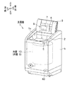
図1に、本発明の実施形態に係る洗濯機の斜視図を示す。なお、図1は、外蓋3を開けた状態を示している。
実施形態の洗濯機1は、外郭を成す筐体kが鋼板と樹脂成型品とを組み合わせて形成されている。筐体kの上部には、樹脂製のトップカバー2が係合、ねじ止め等で取り付けられている。トップカバー2には、洗濯物の出し入れの際に洗濯槽の上部を開閉する外蓋3が折り曲がって開閉自在に取り付けられている。
FIG. 1 shows a perspective view of a washing machine according to an embodiment of the present invention. FIG. 1 shows a state where the outer lid 3 is opened.
In the
外蓋3は、上向きに凸となるように山型状に折れ曲がりつつ後側に開くことで、筐体kの上部に形成される開口部1aを開放する構成である。また、外蓋3は、各種操作ボタンスイッチ6や表示器7を有する操作パネル8を備えている。
操作パネル8は、機体底部に設けた制御部のマイクロコンピュータ40と電気的に接続されている。
The outer lid 3 is configured to open the opening 1a formed in the upper part of the housing k by opening it to the rear side while being bent in a mountain shape so as to be convex upward. The outer lid 3 includes an operation panel 8 having various
The operation panel 8 is electrically connected to the
一方、トップカバー2の前面には、洗濯機1の電源のオン/オフを行う電源スイッチ5が設けられている。
On the other hand, on the front surface of the
筐体k内の開口部1a(図1参照)の後方には、給水電磁弁(図示せず)が設けられている。そして、トップカバー2の後部には、給水電磁弁に水道水を供給するホースを接続する接続口(図示せず)が設けられている。
A water supply solenoid valve (not shown) is provided behind the opening 1a (see FIG. 1) in the housing k. And the connection part (not shown) which connects the hose which supplies tap water to a water supply solenoid valve is provided in the rear part of the
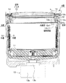
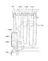
図2に、実施形態の洗濯機の内槽と外槽周りの詳細構造の縦断面図を示す。なお、図2は、実施形態の洗濯機1を左右方向断面で切断したものである。図3は、図2のA部拡大図である。
洗濯機1は、筐体k(図1参照)内に、図2に示すように、内槽9、外槽10、脈動翼盤11(回転翼盤)、流体バランサ12等を有して構成されている。
In FIG. 2, the longitudinal cross-sectional view of the detailed structure around the inner tank and the outer tank of the washing machine of embodiment is shown. In addition, FIG. 2 cuts the
As shown in FIG. 2, the
内槽9は、有底円筒状に形成され、洗濯物の洗濯、脱水等が行われる洗濯兼脱水槽である。内槽9は、鉛直方向に回転軸を有しており、内槽9の下方に設けられる駆動装置13(図2参照)によって回転可能に支持されている。内槽9は、例えばステンレス鋼板(SUS)を用いて溶接等を行って形成されている。
内槽9は、その外周壁および底壁に通水のための複数の小さな貫通孔(図示せず)がそれぞれ形成されている。
The
The
外槽10は、有底円筒状に形成されており、内槽9を同軸上に内包している。外槽10は、筐体k(図1参照)の上端部の四隅部に設けた隅板(不図示)に係止して垂下される4本の支持棒(鋼棒)に緩衝装置(不図示)を介して筐体k内の中心部に弾性支持されている。
外槽10の上縁部には、外槽10と内槽9の上部を覆う外槽カバー14が設けられている。
The
An outer tank cover 14 that covers the upper part of the
<脈動翼盤11>
内槽9の底部には、洗濯物に洗濯やすすぎ時に物理的な力を加えるための脈動翼盤11が設けられている。
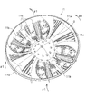
図4に、脈動翼盤の表側の斜視図を示す。
<
At the bottom of the
FIG. 4 is a perspective view of the front side of the pulsating blade.
脈動翼盤11は、中央の回転中心Oの部分が盛り上がって形成されている。そして、脈動翼盤11には、回転中心Oを挟んで対向する位置に凸形状となる凸状部11aと、周方向の凸状部11a、11a間に凹み形状となる凹み部11bが形成されている。これにより、脈動翼盤11は、周方向に凹凸形状が繰り返されるように構成されている。また、脈動翼盤11には、表面と裏面を連通する孔11cが複数個所に形成されている。
The pulsating
脈動翼盤11は、略円盤状に形成され、内槽9の下方の駆動装置13(図2参照)により回転可能に支持されている。つまり、洗濯時やすすぎ時に、駆動装置13により回転翼盤11を回転させることで洗濯水を洗濯物ごと攪拌する構成である。
脈動翼盤11は、内槽9の上部に流体バランサ12を取り付けた後、流体バランサ12の内方から変形させて(図4の矢印α1)内槽9内に入れられる。そして、脈動翼盤11は、駆動装置13の上方に設けられる電磁操作クラッチ機構13bにねじ止め等で固定される。
The pulsating
After the
駆動装置13は、インバータ駆動電動機または可逆回転型のコンデンサ分相単相誘導電動機を使用した電動機13aと、電磁操作クラッチ機構(クラッチ)13bと、遊星歯車減速機構とを内蔵して構成されている。また、駆動装置13は、マイコン40によって電動機13aと電磁操作クラッチ機構13bを制御することによって、洗濯駆動モードと脱水駆動モードとを選択的に実行する機能を有する。
The
洗濯駆動モードとは、内槽9を静止させるように係止または自由に回転できる解放状態で、脈動翼盤11を繰り返し低速で正逆回転させるモードである。
脱水駆動モードとは、内槽9と脈動翼盤11とを一体的に同一方向に高速で回転させる高速回転モードである。
The washing drive mode is a mode in which the pulsating
The dehydration drive mode is a high-speed rotation mode in which the
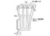
<流体バランサ12>
流体バランサ12は、合成樹脂等でリング状に形成され、内槽9の胴板9dの上端縁部(上縁部)に設けられている。流体バランサ12は、脱水時の内槽9の回転に際して洗濯物iの偏りにより偏心が生じたときに、内部の流体が偏心の反対側に移動することによって偏心を打ち消す。これにより、洗濯物を入れた内槽9の回転のバランスを維持する部材である。流体バランサ12は、流体12cを封入して構成されている。
<
The
図5は、図2のB部拡大図である。流体バランサ12は、横断面で図5に示す断面を有している。
流体バランサ12は、バランスリングケース12aとバランスリング蓋12bと流体12cとを有して構成されている。
バランスリングケース12aは、樹脂成形品であり、例えば、強化ガラス入りのPP(ポリプロピレン)を用いて射出成形される。
FIG. 5 is an enlarged view of a portion B in FIG. The
The
The
バランスリングケース12aは、上部が開口された円環状の部材である。バランスリングケース12aは、内部に内側の短円筒状の内円筒壁12k1と、外側の短円筒状の外円筒壁12k2とが形成されている。2つの隔壁の内円筒壁12k1と外円筒壁12k2とで、流体バランサ12内が3つの円環状の室12r1,12r2、12r3に画成されている。円環状の室12r1,12r2、12r3にはそれぞれ流体12cが入れられている。流体12cは、流体バランサ12の小型化のため、内部に比重の大きな塩水等が封入される。
The
バランスリングケース12aの内周壁12nは、中央上部から下端部にかけて円錐台形状の傾斜周面12n11が形成されている。バランスリングケース12aの内周面12n1と底面12iとが成す角部12dは、図5の横断面視でR形状に形成されている。
The inner
バランスリングケース12aの内周壁12nの円錐台形状の傾斜周面12n11は、後に詳述する内槽9の共振時の平均の最大振幅で内槽9、流体バランサ12が傾斜した際に、洗濯物iに働く遠心力に垂直な方向に対して内槽9側を向く傾斜を有して形成されている。換言すれば、バランスリングケース12aの内周壁12nの傾斜周面12n11は、内槽9が回転する回転軸に対して、内槽9側を向く傾斜を有して形成されている。
The frustoconical inclined peripheral surface 12n11 of the inner
流体バランサ12の内周面12nに、傾斜周面12n11と、これに続くR状の角部12dとが形成されることで、脱水運転時の洗濯物iは、遠心力により流体バランサ12の内周面12n1の傾斜周面12n11から下方の内槽9内に引き込まれる。これにより、洗濯物が内槽9内から外部に飛び出て、流体バランサ12と外槽カバー14との間の隙間sに入ったり、噛み込まれることが抑制される。
By forming an inclined peripheral surface 12n11 and an R-shaped
バランスリングケース12aの外周壁12sの外周下部には、周状の取り付け凸部12tが外方に突出して、矩形状の断面を有して形成されている(図5参照)。
バランスリング蓋12bは、中央に大きな開口を有する略円環板状の形状をもつ部材である。
A
The
バランスリング蓋12bの下部には、第1〜第4の取り付け凹部12b1〜12b4が環状に凹んで形成されている。第1〜第4の取り付け凹部12b1〜12b4には、それぞれバランスリングケース12aの内周壁12n、内円筒壁12k1、外円筒壁12k2、外周壁12sの上部が嵌入される。
First to fourth mounting recesses 12b1 to 12b4 are formed in an annular shape in the lower part of the
流体バランサ12の組立ては、バランスリングケース12aの室12r1,12r2、12r3にそれぞれ流体12cが入れられる。そして、バランスリングケース12aの内周壁12n、内円筒壁12k1、外円筒壁12k2、外周壁12sの上部にそれぞれ、バランスリング蓋12bの下部の第1〜第4の取り付け凹部12b1〜12b4が嵌入させた状態とする。
In assembling the
この状態で、バランスリング蓋12bとバランスリングケース12aとを相対的に高速回転させることにより、摩擦熱で溶融させ、バランスリングケース12aの内周壁12n、内円筒壁12k1、外円筒壁12k2、外周壁12sの上部を、バランスリング蓋12bの下部の第1〜第4の取り付け凹部12b1〜12b4に溶融結合する。これにより、流体バランサ12が組み上がる。
In this state, the
流体バランサ12を内槽9の上部に組み付けるに際しては、流体バランサ12が、内槽9を成すSUSの筒状の胴板9dの上部がL曲げ9d1で取り付け凸部12tに固着される。そして、流体バランサ12が胴板9dに複数個所ボルト締めされることにより固定される。
When the
<脱水運転時の内槽9と外槽10との動的挙動>
図6(a)は、脱水運転時の内槽9の回転速度と、内槽9、外槽10の上部の振動振幅との関係を示す図である。横軸に内槽9の回転速度をとり、縦軸に内槽9、外槽10の振動振幅をとっている。図6(b)〜(d)は、脱水運転時の内槽9、外槽10の1次共振、2次共振、3次共振の状態を模式的に示した図である。
<Dynamic behavior of
FIG. 6A is a diagram showing the relationship between the rotation speed of the
なお、外槽10の振動振幅の測定に際しては、外槽10の前後左右を上部と下部で合計8か所レーザ式の位置検出器で測定した。また、内槽9の振動振幅の測定に際しては、外槽10と内槽9との間に、粘土を貼り付けて当該粘度の変形状態から内槽9の振動振幅を測定した。
When measuring the vibration amplitude of the
洗濯機1で脱水運転を行うと、脱水開始から脱水運転の最大回転速度(最大回転数)までにおいて、1次共振、2次共振、3次共振の大きな振動振幅が観察される。1次共振は、内槽9の回転速度約80rpmであり、3次共振は、内槽9の回転速度約1100rpmである。
When the
1次共振は、図6(b)に示すように、内槽9と外槽10とが共に、1方向に往復直線運動する並進運動が観察される。
2次共振は、図6(c)に示すように、内槽9と外槽10とが共に、内槽9の回転軸点O1中心に、ゴマを摺るような振れ回る運動が観察される。この運動をゴマすり運動と称する。
3次共振は、図6(d)に示すように、内槽9と外槽10とが逆の位相で、内槽9の回転軸上の点O2中心に、振れ回る運動が観察される。この運動を、内槽・外槽逆位相のゴマすり運動と称する。
In the primary resonance, as shown in FIG. 6B, a translational motion in which the
In the secondary resonance, as shown in FIG. 6 (c), both the
In the third resonance, as shown in FIG. 6D, the
内槽9の回転速度は、3次共振より小さいので、洗濯物iが外槽カバー14と流体バランサ12との間に入り込んだり、噛み込まれる現象は、1次共振と2次共振とが問題になる。
そして、2次共振時に内槽9が大きく傾くことから、洗濯物iの外槽カバー14と流体バランサ12との間の隙間sに入り込みまたは噛み込みが発生する(図17(a)、(b)参照)と考えられる。
Since the rotation speed of the
Then, since the
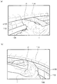
図7(a)は、1次共振時の比較例11(従来)の洗濯機の洗濯物iの挙動を白抜き矢印で示した内槽、外槽の上部を示す縦断面図であり、図7(b)は、2次共振時の比較例11の洗濯機の洗濯物の挙動を矢印で示した内槽、外槽の上部を示す縦断面図である。 FIG. 7A is a longitudinal cross-sectional view showing the upper part of the inner tub and the outer tub, in which the behavior of the laundry i of the washing machine of Comparative Example 11 (conventional) at the time of primary resonance is indicated by a white arrow. 7 (b) is a longitudinal sectional view showing the upper part of the inner tub and the outer tub indicated by arrows with respect to the behavior of the laundry of the washing machine of Comparative Example 11 at the time of secondary resonance.
比較例11では、内槽109の脱水運転の1次共振時に、図7(a)に示すように、内槽109の回転時の外方への遠心力Fにより、洗濯物iが外槽カバー114と流体バランサ112との間の隙間s100に入り込んだり、噛み込まれる現象が観察される。
In Comparative Example 11, at the time of the primary resonance of the dehydrating operation of the
比較例11では、内槽109の脱水運転の2次共振時に、図7(b)に示すように、内槽109の高速回転時の外方への遠心力Fにより、洗濯物iが流体バランサ112の内周面112n1を滑って、外槽カバー114と流体バランサ112との間の隙間s100に入り込んだり、噛み込まれる現象が観察される。これは、比較例1の流体バランサ112の内周面112n1は、内槽109の回転軸の方向に沿った形状を有している(図16参照)。
In Comparative Example 11, during the secondary resonance of the dewatering operation of the
そのため、2次共振時に、内槽109が傾くと、内槽109の上部に固定される流体バランサ112が傾き、流体バランサ112の内周面112n1が、図7(b)に示すように、上向きの傾斜を有する状態になる。そのため、流体バランサ112近くの洗濯物iは、内槽109の高速回転時の外方への遠心力Fにより、流体バランサ112の上向きの傾斜の内周面121n1を滑って外槽カバー114と流体バランサ112との間の隙間s100に入り込んだり、噛み込まれると考えられる。
Therefore, when the
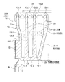
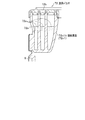
図8は、2次共振時の実施形態の洗濯機の洗濯物に働く力を矢印で示した内槽、外槽の上部を示す縦断面図である。
これに対して、実施形態の洗濯機1では、図5に示すように、洗濯機1を運転しない状態において、流体バランサ12の内周壁12nの中央から下部にかけて、予め傾斜周面12n11と、これに続くR状の角部12dとが形成されている。
FIG. 8 is a longitudinal sectional view showing the upper part of the inner tub and the outer tub in which forces acting on the laundry of the washing machine of the embodiment at the time of the secondary resonance are indicated by arrows.
On the other hand, in the
前記したように、流体バランサ12の傾斜周面12n11の傾斜は、少なくとも共振時の平均の最大振幅に際して内槽9、流体バランサ12が傾斜した際に、回転する内槽9の回転軸に対して内槽9側を向く傾斜(鉛直より下方向を向く傾斜)を有している。つまり、流体バランサ12の内周面12n1に、脱水運転時に内槽9が振動して傾いた際に内槽9側に向いて傾斜する傾斜周面2n11を有している
As described above, the inclination of the inclined peripheral surface 12n11 of the
そのため、内槽9の高速回転による遠心力Fにより洗濯物iは水平外方向の外力を受けるが、流体バランサ12の内周壁12nの傾斜周面12n11と、これに続くR状の角部12dとは下方の内槽9側に向く傾斜を有しているので、図8の矢印に示すように、洗濯物iへの遠心力は、洗濯物iを下方の内槽9側への力となって働く。
Therefore, the laundry i receives external force in the horizontal outer direction due to the centrifugal force F generated by the high-speed rotation of the
従って、洗濯物iは、内槽9側を向く流体バランサ12の内周壁12nの傾斜周面12n11と、これに続くR状の角部12dに案内されて、下方の内槽9内に引き込まれる。これによって、脱水運転時に、洗濯物が内槽9および流体バランサ12の外方に飛び出ることが抑制される。そのため、脱水運転時に、洗濯物iが外槽カバー14と流体バランサ12との間の隙間s(図3参照)に入り込んだり、噛み込まれることが抑制される。
Accordingly, the laundry i is guided by the inclined peripheral surface 12n11 of the inner
<比較例1と比較例2と実施形態での洗濯物の入り込み状態の比較>
次に、比較例1と実施形態において、洗濯容量を10kgから11kgにアップした際の外槽カバー14と流体バランサ12との間の隙間sに入り込み現象の実証結果について説明する。
比較例1と比較例2と実施形態の流体バランサでの洗濯物の入り込み状態を、同じ大きさの洗濯兼脱水槽の内槽109、9を用いて比較したデータを以下に示す。
実験条件は、負荷が試験布であり、洗剤なしで、標準コースを30回繰り返したものである。
<Comparison of entering state of laundry in comparative example 1, comparative example 2 and embodiment>
Next, in Comparative Example 1 and the embodiment, the verification result of the phenomenon of entering the gap s between the
The data which compared the entering state of the laundry in the fluid balancer of the comparative example 1 and the comparative example 2 and the embodiment using the
The experimental conditions were a test cloth loaded, a standard course repeated 30 times without detergent.
図9は、比較例1と比較例2と実施形態とでの洗濯物の外槽カバーと流体バランサとの間の隙間への入り込みを比較する実験を行った流体バランサの横断面図である。図9(a)は、比較例1(従来)の流体バランサの横断面図であり、図9(b)は、比較例2の流体バランサの横断面図であり、図9(c)は、実施形態の流体バランサの横断面図である。 FIG. 9 is a cross-sectional view of a fluid balancer in which experiments for comparing the entry of the laundry into the gap between the outer tub cover and the fluid balancer in Comparative Example 1, Comparative Example 2, and the embodiment were performed. 9A is a cross-sectional view of the fluid balancer of Comparative Example 1 (conventional), FIG. 9B is a cross-sectional view of the fluid balancer of Comparative Example 2, and FIG. It is a cross-sectional view of the fluid balancer of the embodiment.
図9(a)の比較例1は、横断面視で、流体バランサ112の内周壁112nの内周面112n1の下角部112n2のR形状の半径(Rの半径)を小さくしたものである。比較例1は、前記したように、下角部112n2のRを小さくすることで洗濯物iを下方の内槽109内へ抑え込む(図9(a)の白抜き矢印)ことを図っている。
In Comparative Example 1 of FIG. 9A, the R-shaped radius (R radius) of the lower corner portion 112n2 of the inner peripheral surface 112n1 of the inner
図9(b)の比較例2は、横断面視で、流体バランサ22の内周壁22nを、内周面22n1の下部が凹部22noをもつような形状に形成している。そして、凹部22noの内方端に下向きのボッチ(凸部)22n2を形成したものである。比較例2は、内周面22n1の下部の凹部22noと下向きのボッチ22n2とで、洗濯物iを下方の内槽9内へ抑え込む(図9(b)の白抜き矢印)ことを図ったものある。
In Comparative Example 2 of FIG. 9B, the inner
図9(c)の実施形態の流体バランサ12は、横断面視で、前記した流体バランサ12の内周面12n1に傾斜周面12n11を形成するとともに内周壁12nの内下端の角部12dをR状に形成したものである。実施形態では、脱水時の遠心力で、洗濯物iを下方の内槽9内に引き込む(図9(c)の白抜き矢印)ことを狙ったものである。
表1に比較例1と比較例2と実施形態の流体バランサでの洗濯物の入り込み状態の実験結果を示す。
The
Table 1 shows the experimental results of the laundry entering state in the fluid balancer of Comparative Example 1, Comparative Example 2, and the embodiment.

表1から、洗濯容量10kgの比較例1の洗濯物の入り込み率は13%で、使用に耐え得る値であった。目標値の13%は、実際の洗濯機1の使用実績を満足する(洗濯機1の実用に耐え得る)入り込み率である。 From Table 1, the penetration rate of the laundry of Comparative Example 1 having a washing capacity of 10 kg was 13%, which was a value that could be used. 13% of the target value is a penetration rate that satisfies the actual usage record of the washing machine 1 (can withstand practical use of the washing machine 1).
洗濯容量11kgで、内槽109、9の大きさを変えることなく洗濯容量を10kgから11kgにアップすると、比較例1、比較例2では、入り込み率23%と実用に耐え得る値(少なくとも入り込み率13%)は得られなかった。一方、実施形態では、洗濯容量を11kgにアップしても、入り込み率13%と目標値を満足する結果が得られた。
以上の結果から、実施形態の構成(図5、図9(c)の構成)により、内槽9の大きさを変えることなく、洗濯容量のアップが図れることが実証された。
When the washing capacity is increased from 10 kg to 11 kg without changing the size of the
From the above results, it was proved that the laundry capacity can be increased without changing the size of the
<流体バランサ12における流体12cを入れる室12r1,12r2、12r3の容積>
ここで、図5に示すように、流体バランサ12の内周壁12nに傾斜周面12n11を形成する場合、必然的に流体バランサ12内に入れる流体の容積が小さくなることが考えられる。
しかし、本洗濯機1では、内槽9への流体バランサ12への脈動翼盤11と流体バランサ12との取り付けを、内槽9の上部に流体バランサ12を取り付けた後に脈動翼盤11を取り付けることとしている。
<Volumes of chambers 12r1, 12r2, and 12r3 into which the fluid 12c in the
Here, as shown in FIG. 5, when the inclined
However, in the
具体的には、前記したように、内槽9を成すSUSの筒状の胴板9dのL曲げ9d1により流体バランサ12が内槽9の上部に固着される。そして、L曲げ9d1で位置決めされた流体バランサ12を胴板9dに複数個所ボルト締めして、流体バランサ12が内槽9の上部に固定される。
Specifically, as described above, the
その後、流体バランサ12を、図5の矢印α1に示すように、内側等に変形させて、内槽9の上部に固定した流体バランサ12の内方から、内槽9内の下部に入れ、電磁操作クラッチ機構13bにねじ止め等で固定される。
そのため、本洗濯機1では、内槽9と流体バランサ12との間に他部材(例えば比較例1のウェルディング109w(図10参照))が配置されないので、流体バランサ12内に流体12cを入れる室12r1,12r2、12r3の容積がウェルディング109wにより減らされることなく、充分に確保することができる。
Thereafter, the
For this reason, in the
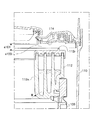
図10は、比較例1の流体バランサを示す拡大断面図である。
これに対して、比較例1(従来)では、内槽109に流体バランサ112を取り付ける前に、脈動翼盤を変形させないで、電磁操作クラッチ機構13bに固定する構造であった。ここで、比較例1では、脈動翼盤を変形させないで電磁操作クラッチ機構13bに固定することから、脈動翼盤の外径が大きいため、固定に際して必然的に流体バランサ112の内方を通すことができない。
FIG. 10 is an enlarged cross-sectional view showing a fluid balancer of Comparative Example 1.
On the other hand, Comparative Example 1 (conventional) has a structure in which the pulsation blade is fixed to the electromagnetically operated
そこで、比較例1では、環状のウェルディング109wという流体バランサ112を内槽109の上部に取り付けるための部材を内槽109上部に固定する。そして、脈動翼盤を電磁操作クラッチ機構13bに固定した後に、流体バランサ112を、内槽109の上部に固定されたウェルディング109wに取り付けている。
Therefore, in Comparative Example 1, a member for attaching the
具体的には、図10に示すように、内槽109を成すSUSの筒状の胴板109dをL曲げ109d1して内槽109の上部に環状のウェルディング109wを固着する。そして、L曲げ9d1で位置決めされたウェルディング109wを胴板109dに複数個所ボルト締めして、ウェルディング109wが内槽9の上部に固定される。
Specifically, as shown in FIG. 10, a
その後、脈動翼盤を、内槽109の上部から、内槽109の上部に固定されるウェルディング109wの内方を通して電磁操作クラッチ機構13bにねじ止め等で固定される。その後、流体バランサ112を内槽109の上部に固定されるウェルディング109wに取り付けている。
Thereafter, the pulsation blade is fixed to the electromagnetic operation
そのため、比較例1では、流体112cが入れられる円環状の室112r1,112r2、112r3のうち最も外側の112r3室の容積がウェルディング109wが配置される分狭くなっていた。流体112cの量が少なくなると、内槽109の脱水運転時の振動の抑制効果が減殺されるため、流体112cの量は一定量確保する必要がある。
Therefore, in Comparative Example 1, the volume of the outermost 112r3 chamber out of the annular chambers 112r1, 112r2, 112r3 into which the fluid 112c is placed is narrowed by the amount of the
一方、本洗濯機1では、脈動翼盤11を変形させて電磁操作クラッチ機構13bに固定する構成であることから、比較例1で用いていた環状のウェルディング109wを無くすことができる。そのため、流体バランサ12の流体12cを入れる室12r1,12r2、12r3の容積が環状のウェルディングで減ることがなく、流体バランサ12の室12r1,12r2、12r3の容積が充分に確保される。
On the other hand, since the
従って、図5に示すように、流体バランサ12の室12r3の容積に食い込む形状となる内周面12n1の傾斜周面12n11を形成しても、流体バランサ12に、必要な流体12cを入れる容積を確保することができる。
流体バランサ12の内周面12n1に傾斜周面12n11を形成することで、内槽9と流体バランサ12とで形成される容積が大きくでる。そのため、洗濯容量を増加できるとう効果もある。
Therefore, as shown in FIG. 5, even if the inclined peripheral surface 12n11 of the inner peripheral surface 12n1 is formed so as to bite into the volume of the chamber 12r3 of the
By forming the inclined peripheral surface 12n11 on the inner peripheral surface 12n1 of the
<変形例1>
図11に、変形例1の流体バランサの横断面図を示す。
変形例1の流体バランサ32は、実施形態で説明した傾斜周面12n11を、下方の内槽9側に向く曲率をもったえぐり込んだ形状の凹状曲部の傾斜周面32n11としてバランスリングケース32aに形成したものである。
変形例1のえぐり込んだ形状の凹状曲部の傾斜周面32n11では下方(内槽9側)への傾斜が大きくでき、洗濯物iを下方の内槽9内への引き込む効果が大である。
<
In FIG. 11, the cross-sectional view of the fluid balancer of the
The fluid balancer 32 of the first modification includes the
In the inclined circumferential surface 32n11 of the concave curved portion of the recessed shape of the modified example 1, the inclination downward (
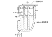
<変形例2>
図12に、変形例2の流体バランサの横断面図を示す。
変形例2の流体バランサ42は、実施形態で説明した傾斜周面12n11を、下方の内槽9側に向く曲率をもった凸状の曲率をもった形状の傾斜周面42n11として、バランスリングケース42aに形成したものである。
<
In FIG. 12, the cross-sectional view of the fluid balancer of the
The fluid balancer 42 according to the modified example 2 uses the inclined peripheral surface 12n11 described in the embodiment as an inclined peripheral surface 42n11 having a convex curvature with a curvature directed toward the lower
変形例2の傾斜周面42n11では下方の内槽9への傾斜が下部で大きくでき、洗濯物iを下方の内槽9内へ引き込み効果が大である。また、凸状の曲率をもった形状の凸状曲部42n11であるため、流体バランサ42内の容量を維持でき、流体42cの量を確保できる。
In the inclined peripheral surface 42n11 of the
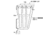
<変形例3>
図13に、変形例3の流体バランサの横断面図を示す。
変形例3の流体バランサ52は、実施形態で説明した傾斜周面12n11を、内周面52n1の上端縁から下端縁に亘る形状の傾斜周面52n11としてバランスリングケース52aに形成したものである。
<Modification 3>
In FIG. 13, the cross-sectional view of the fluid balancer of the modification 3 is shown.
The fluid balancer 52 of Modification 3 is formed by forming the inclined peripheral surface 12n11 described in the embodiment in the
変形例3によれば、傾斜周面52n11が内周面52n1の上端縁から下端縁に亘って形成されるので、洗濯物iに流体バランサ52の内周面52n1全体で内槽9内に引き込む力を与えることができる。従って、洗濯物iが内槽9の脱水運転の振動時に内槽9から飛び出し、内槽9と外槽カバー14との間の隙間sに入り込んだり、噛み込まれたりすることを効果的に抑制できる。
According to the modification 3, since the inclined peripheral surface 52n11 is formed from the upper end edge to the lower end edge of the inner peripheral surface 52n1, the entire inner peripheral surface 52n1 of the fluid balancer 52 is drawn into the
<変形例4>
図14に、変形例4の流体バランサの横断面図を示す。
変形例4の流体バランサ62は、変形例1で説明した下方(内槽9側)に向く曲率をもったえぐり込んだ形状の凹状曲部の傾斜周面32n11を、内周面62n1の上端縁から下端縁に亘るえぐり込んだ形状の凹状曲部の傾斜周面62n11として、バランスリングケース62aに形成したものである。
<Modification 4>
In FIG. 14, the cross-sectional view of the fluid balancer of the modification 4 is shown.
The fluid balancer 62 of the modified example 4 has an inclined peripheral surface 32n11 of a concavely curved concave portion having a curvature facing downward (
変形例4では、バランスリングケース62aに内周面62n1の上端縁から下端縁に亘ってえぐり込んだ形状の凹状曲部の傾斜周面62n11が形成されるので、洗濯物iを流体バランサ62の内周面62n1全体で内槽9に引き込む力を与えることができる。そのため、洗濯物iを下方の内槽9内へ引き込む傾斜が大きくでき、洗濯物iを下方の内槽9に引き込み効果が大きい。
In the modified example 4, since the inclined peripheral surface 62n11 of the concave curved portion is formed in the
<変形例5>
図15に、変形例5の流体バランサの横断面図を示す。
変形例5の流体バランサ72は、変形例2で説明した下方(内槽9側)に向く曲率をもった凸状の曲率をもつ形状の凸状曲部の傾斜周面42n11を、内周面72n1の上端縁から下端縁に亘る下方に向く凸状の曲率を有する形状の傾斜周面72n11として、バランスリングケース72aに形成したものである。
<
In FIG. 15, the cross-sectional view of the fluid balancer of the
The fluid balancer 72 of the modified example 5 has the inclined circumferential surface 42n11 of the convex curved portion having a convex curvature having a curvature facing downward (
変形例5では、バランスリングケース72aに内周面72n1の上端縁から下端縁に亘って凸状の曲率をもった形状の傾斜周面72n11が形成されるので、洗濯物iを流体バランサ72の内周面72n1全体で内槽9内に引き込む力を与えることができる。
また、凸状の曲率をもった形状の傾斜周面72n11であるため、流体バランサ72内の容量を維持でき、流体72cの量を確保できる。
In the modified example 5, since the inclined peripheral surface 72n11 having a convex curvature is formed on the
Moreover, since it is the inclined peripheral surface 72n11 of a shape with a convex curvature, the capacity | capacitance in the fluid balancer 72 can be maintained and the quantity of the fluid 72c can be ensured.
<<その他の実施形態>>
1.前記実施形態、変形例では、鉛直方向に洗濯槽の回転軸をもつ縦型の洗濯機を例示して説明したが、略水平方向にドラムの回転軸をもち、洗濯、脱水の各工程を行うドラム式洗濯機、および、洗濯、脱水の各工程に加えて、乾燥の工程を行うドラム式洗濯乾燥機にも、本発明を適用可能である。
<< Other Embodiments >>
1. In the embodiment and the modification, the vertical washing machine having the rotation axis of the washing tub in the vertical direction has been described as an example, but the rotation axis of the drum is provided in the substantially horizontal direction, and each process of washing and dehydration is performed. The present invention can also be applied to a drum-type washing machine and a drum-type washing / drying machine that performs a drying process in addition to the washing and dewatering processes.
ドラム式洗濯機、ドラム式洗濯乾燥機の場合、ドラムの開口に設ける流体バランサの内周面に、脱水運転時にドラムが振動して傾いた際にドラム側を向く傾斜をもつ傾斜周面(洗濯物が受ける遠心力に垂直な方向に対してドラム側を向く傾斜周面)を設ける。 In the case of a drum-type washing machine or drum-type washing / drying machine, an inclined peripheral surface having a slope facing the drum side when the drum is vibrated and tilted during dehydration operation is provided on the inner peripheral surface of the fluid balancer provided at the opening of the drum (washing An inclined peripheral surface facing the drum side with respect to a direction perpendicular to the centrifugal force received by the object is provided.
2.ドラム式洗濯機、ドラム式洗濯乾燥機にも、実施形態の構成のみならず変形例1〜5の構成を適用できる。
2. Not only the configuration of the embodiment but also the configurations of
3.前記実施形態、変形例で説明した構成は、本発明の一例を示したものであり、本願の特許請求の範囲内で様々な具体的な形態、変形形態が可能である。 3. The configurations described in the above embodiments and modifications are examples of the present invention, and various specific forms and modifications can be made within the scope of the claims of the present application.
1 洗濯物
9 内槽
10 外槽
12、22、32、42、52、62、72 流体バランサ
12c 流体
12n1 内周面
F 遠心力
12n11 傾斜周面
12d 下端部のR形状
32n11、62n11 傾斜周面(凹状の曲率の傾斜周面)
42n11、72n11 傾斜周面(凸状の曲率の傾斜周面)
52n11 傾斜周面(上端縁から下端縁まで形成される傾斜周面)
DESCRIPTION OF
42n11, 72n11 inclined peripheral surface (inclined peripheral surface with convex curvature)
52n11 inclined peripheral surface (inclined peripheral surface formed from the upper edge to the lower edge)
Claims (4)
前記内槽の上部に設けられ、前記内槽の脱水運転時の振動を抑制する内部に流体を有する環状の流体バランサと、
洗濯水を溜め、前記内槽を収容する外槽とを備え、
前記流体バランサは、
その内周面に、脱水運転時に前記内槽が振動して傾いた際に前記内槽側に向いて傾斜する傾斜周面を有している
ことを特徴とする洗濯機。 A laundry washing and dewatering tank inner tub,
An annular fluid balancer provided in the upper part of the inner tank and having a fluid inside to suppress vibration during dehydration operation of the inner tank;
Storing the wash water, and comprising an outer tub for accommodating the inner tub,
The fluid balancer is
The washing machine, wherein the inner peripheral surface has an inclined peripheral surface that inclines toward the inner tub when the inner tub is vibrated and inclined during a dehydrating operation.
前記流体バランサの内周奥の角部は、横断面視で、曲率をもつR形状に形成されている
ことを特徴とする洗濯機。 The washing machine according to claim 1,
A corner of the inner periphery of the fluid balancer is formed in an R shape having a curvature in a cross-sectional view.
前記流体バランサの前記傾斜周面は、
前記内槽の脱水運転での共振時の平均の最大振幅において前記回転軸に対して前記内槽側に向いて傾斜している
ことを特徴とする洗濯機。 The washing machine according to claim 1,
The inclined peripheral surface of the fluid balancer is
The washing machine, wherein the inner tank is inclined toward the inner tub side with respect to the rotation axis at an average maximum amplitude during resonance in the dehydrating operation of the inner tub.
前記流体バランサの前記傾斜周面は、凹状の曲率または凸状の曲率を有している
ことを特徴とする洗濯機。 The washing machine according to claim 1,
The washing machine, wherein the inclined peripheral surface of the fluid balancer has a concave curvature or a convex curvature.
Priority Applications (2)
| Application Number | Priority Date | Filing Date | Title |
|---|---|---|---|
| JP2015085968A JP2016202444A (en) | 2015-04-20 | 2015-04-20 | Washing machine |
| TW105111082A TWI592539B (en) | 2015-04-20 | 2016-04-08 | Washing machine |
Applications Claiming Priority (1)
| Application Number | Priority Date | Filing Date | Title |
|---|---|---|---|
| JP2015085968A JP2016202444A (en) | 2015-04-20 | 2015-04-20 | Washing machine |
Publications (2)
| Publication Number | Publication Date |
|---|---|
| JP2016202444A true JP2016202444A (en) | 2016-12-08 |
| JP2016202444A5 JP2016202444A5 (en) | 2017-10-05 |
Family
ID=57486606
Family Applications (1)
| Application Number | Title | Priority Date | Filing Date |
|---|---|---|---|
| JP2015085968A Pending JP2016202444A (en) | 2015-04-20 | 2015-04-20 | Washing machine |
Country Status (2)
| Country | Link |
|---|---|
| JP (1) | JP2016202444A (en) |
| TW (1) | TWI592539B (en) |
Cited By (6)
| Publication number | Priority date | Publication date | Assignee | Title |
|---|---|---|---|---|
| JP2018175394A (en) * | 2017-04-13 | 2018-11-15 | 日立アプライアンス株式会社 | Washing machine |
| JP2018192176A (en) * | 2017-05-22 | 2018-12-06 | 日立アプライアンス株式会社 | Washing and drying machine |
| CN110241560A (en) * | 2018-03-07 | 2019-09-17 | 青岛海尔洗衣机有限公司 | A kind of balanced ring for washing machine and washing machine |
| CN112522925A (en) * | 2019-09-17 | 2021-03-19 | 日立环球生活方案株式会社 | Washing machine |
| WO2022068055A1 (en) * | 2020-09-30 | 2022-04-07 | 无锡小天鹅电器有限公司 | Tub body assembly and laundry treatment apparatus |
| CN114616370A (en) * | 2019-11-06 | 2022-06-10 | 青岛海尔洗衣机有限公司 | Washing machine |
Families Citing this family (1)
| Publication number | Priority date | Publication date | Assignee | Title |
|---|---|---|---|---|
| JP2019150233A (en) * | 2018-03-01 | 2019-09-12 | 日立グローバルライフソリューションズ株式会社 | Washing machine |
Citations (4)
| Publication number | Priority date | Publication date | Assignee | Title |
|---|---|---|---|---|
| JPS50106278U (en) * | 1974-02-06 | 1975-09-01 | ||
| JPH07144085A (en) * | 1993-11-24 | 1995-06-06 | Sanyo Electric Co Ltd | Stirring vane for washing machine |
| JPH0884889A (en) * | 1994-09-19 | 1996-04-02 | Toshiba Corp | Fully automatic washing machine |
| JPH08229282A (en) * | 1995-02-27 | 1996-09-10 | Matsushita Electric Ind Co Ltd | Fully automatic washing machine |
-
2015
- 2015-04-20 JP JP2015085968A patent/JP2016202444A/en active Pending
-
2016
- 2016-04-08 TW TW105111082A patent/TWI592539B/en active
Patent Citations (4)
| Publication number | Priority date | Publication date | Assignee | Title |
|---|---|---|---|---|
| JPS50106278U (en) * | 1974-02-06 | 1975-09-01 | ||
| JPH07144085A (en) * | 1993-11-24 | 1995-06-06 | Sanyo Electric Co Ltd | Stirring vane for washing machine |
| JPH0884889A (en) * | 1994-09-19 | 1996-04-02 | Toshiba Corp | Fully automatic washing machine |
| JPH08229282A (en) * | 1995-02-27 | 1996-09-10 | Matsushita Electric Ind Co Ltd | Fully automatic washing machine |
Cited By (9)
| Publication number | Priority date | Publication date | Assignee | Title |
|---|---|---|---|---|
| JP2018175394A (en) * | 2017-04-13 | 2018-11-15 | 日立アプライアンス株式会社 | Washing machine |
| JP2018192176A (en) * | 2017-05-22 | 2018-12-06 | 日立アプライアンス株式会社 | Washing and drying machine |
| CN110241560A (en) * | 2018-03-07 | 2019-09-17 | 青岛海尔洗衣机有限公司 | A kind of balanced ring for washing machine and washing machine |
| CN110241560B (en) * | 2018-03-07 | 2023-01-24 | 青岛海尔洗衣机有限公司 | Washing machine balance ring and washing machine |
| CN112522925A (en) * | 2019-09-17 | 2021-03-19 | 日立环球生活方案株式会社 | Washing machine |
| CN112522925B (en) * | 2019-09-17 | 2022-10-14 | 日立环球生活方案株式会社 | Washing machine |
| CN114616370A (en) * | 2019-11-06 | 2022-06-10 | 青岛海尔洗衣机有限公司 | Washing machine |
| CN114616370B (en) * | 2019-11-06 | 2023-09-19 | 青岛海尔洗衣机有限公司 | washing machine |
| WO2022068055A1 (en) * | 2020-09-30 | 2022-04-07 | 无锡小天鹅电器有限公司 | Tub body assembly and laundry treatment apparatus |
Also Published As
| Publication number | Publication date |
|---|---|
| TWI592539B (en) | 2017-07-21 |
| TW201638425A (en) | 2016-11-01 |
Similar Documents
| Publication | Publication Date | Title |
|---|---|---|
| JP2016202444A (en) | Washing machine | |
| US9657422B2 (en) | Washing machine | |
| US9970144B2 (en) | Laundry treatment apparatus | |
| JP5469102B2 (en) | Washing machine | |
| JP6750162B2 (en) | Washing machine | |
| JP2011041646A (en) | Washing machine | |
| JP6502087B2 (en) | How to design a washing machine | |
| CN107429465B (en) | Washing machine | |
| TW201730400A (en) | Washing machine | |
| KR102351658B1 (en) | Washing machine | |
| KR20130116633A (en) | Washing machine having damping apparatus | |
| JP5639979B2 (en) | Drum type washer / dryer | |
| JP5568124B2 (en) | Washing machine | |
| JP5269917B2 (en) | Washing machine | |
| JP6025264B2 (en) | Washing machine | |
| KR20210056316A (en) | Top load type washing machine | |
| JP5531048B2 (en) | Washing machine | |
| RU2716550C2 (en) | Household appliance with extruded elements on walls | |
| CN107075772B (en) | Top-opening washing machine | |
| KR102252579B1 (en) | Top load type washing machine | |
| JP2012143289A (en) | Washing machine | |
| CN110832134B (en) | Clothes treating apparatus | |
| JP2017164255A (en) | Washing machine | |
| JP2002045594A (en) | Washing machine | |
| JP6581430B2 (en) | Drum washing machine |
Legal Events
| Date | Code | Title | Description |
|---|---|---|---|
| A521 | Request for written amendment filed |
Free format text: JAPANESE INTERMEDIATE CODE: A523 Effective date: 20170825 |
|
| A621 | Written request for application examination |
Free format text: JAPANESE INTERMEDIATE CODE: A621 Effective date: 20170825 |
|
| A977 | Report on retrieval |
Free format text: JAPANESE INTERMEDIATE CODE: A971007 Effective date: 20180618 |
|
| A131 | Notification of reasons for refusal |
Free format text: JAPANESE INTERMEDIATE CODE: A131 Effective date: 20180626 |
|
| A521 | Request for written amendment filed |
Free format text: JAPANESE INTERMEDIATE CODE: A523 Effective date: 20180809 |
|
| A02 | Decision of refusal |
Free format text: JAPANESE INTERMEDIATE CODE: A02 Effective date: 20181113 |