JP2016201742A - Moving image data for stereoscopic vision generation device, method executed thereby, and moving image display device for stereoscopic vision - Google Patents
Moving image data for stereoscopic vision generation device, method executed thereby, and moving image display device for stereoscopic vision Download PDFInfo
- Publication number
- JP2016201742A JP2016201742A JP2015081942A JP2015081942A JP2016201742A JP 2016201742 A JP2016201742 A JP 2016201742A JP 2015081942 A JP2015081942 A JP 2015081942A JP 2015081942 A JP2015081942 A JP 2015081942A JP 2016201742 A JP2016201742 A JP 2016201742A
- Authority
- JP
- Japan
- Prior art keywords
- image
- data
- eye
- moving image
- image light
- Prior art date
- Legal status (The legal status is an assumption and is not a legal conclusion. Google has not performed a legal analysis and makes no representation as to the accuracy of the status listed.)
- Pending
Links
Images


Landscapes
- Stereoscopic And Panoramic Photography (AREA)
- Testing, Inspecting, Measuring Of Stereoscopic Televisions And Televisions (AREA)
Abstract
Description
本発明は、主に、立体視用の動画を生成するための技術に関する。 The present invention mainly relates to a technique for generating a moving image for stereoscopic viewing.
動画よる立体視を行う場合には、ユーザの右目に右目用動画を、左目に左目用動画を見せることにより、これを実現する。
右目用動画と左目用動画とをユーザの右目と左目に導く場合には、それらを表示するための少なくとも1つのディスプレイが必要となる。ディスプレイは、1つの場合と2つの場合がある。
ディスプレイが1つの場合には一般に、ディスプレイに右目用動画を構成するフレームと、左目用動画を構成するフレームとを交互に写す。そして、右目用動画を構成するフレームからの光を右目に、左目用動画を構成するフレームからの光を左目に、時分割、或いは視差分割で、ユーザの目にそれぞれ導くことにより、ユーザの右目に右目用動画を、ユーザの左目に左目用動画を、それぞれ見せることになる。時分割の場合には、ディスプレイには、1フレーム毎に交互に右目用動画を構成するフレームと左目用動画を構成するフレームが表示される。ユーザは、1フレーム毎に交互に表示される右目用動画のフレームと左目用動画のフレームとを、ディスプレイに表示されるフレームの切替タイミングに同期して交互に開閉する液晶シャッタを左右の両目の前にそれぞれ位置させられる特殊な眼鏡等を用いて見ることにより、立体視を行うことができる。他方、視差分割の場合には、ディスプレイに表示されるすべてのフレームの中に、右目用動画を構成する部分と、左目用動画を構成する部分とが表示される。1つのフレームの中に映しだされる右目用動画を構成する部分と、左目用動画を構成する部分とから出た光は、例えば、視野バリア又はレンチキュラーレンズを用いて右目と左目のそれぞれに、分離して導かれる。それにより、ユーザは立体視を行うことができる。
他方、ディスプレイが2つの場合には、右目用動画を表示する右ディスプレイと、左目用動画を表示する左ディスプレイとを準備し、当初から別の物となっている2つのディスプレイそれぞれからの像光を、例えばレンズを含む適当な光学系でユーザの右目と左目とに導くことにより、ユーザは立体視を行う。
When performing stereoscopic viewing using a moving image, this is realized by showing the moving image for the right eye on the right side of the user and the moving image for the left eye on the left side of the user.
When the right-eye moving image and the left-eye moving image are guided to the user's right eye and left eye, at least one display for displaying them is required. There can be one display and two displays.
In the case of a single display, generally, a frame constituting the right-eye moving image and a frame constituting the left-eye moving image are alternately displayed on the display. Then, by guiding the light from the frame constituting the right-eye moving image to the right eye and the light from the frame constituting the left-eye moving image to the user's eyes by time division or parallax division, the user's right eye The right eye moving image and the left eye moving image are shown to the left eye of the user. In the case of time division, the frame constituting the right-eye moving image and the frame constituting the left-eye moving image are alternately displayed on the display for each frame. The user opens a liquid crystal shutter that alternately opens and closes the right-eye moving image frame and the left-eye moving image frame that are alternately displayed for each frame in synchronization with the switching timing of the frame displayed on the display. Stereoscopic viewing can be performed by using special glasses or the like that are positioned in front of each other. On the other hand, in the case of the parallax division, a part constituting the moving picture for the right eye and a part constituting the moving picture for the left eye are displayed in all the frames displayed on the display. Light emitted from the part constituting the moving image for the right eye and the part constituting the moving image for the left eye projected in one frame, for example, to each of the right eye and the left eye using a visual field barrier or a lenticular lens, Guided separately. Thereby, the user can perform a stereoscopic view.
On the other hand, when there are two displays, a right display that displays a right-eye moving image and a left display that displays a left-eye moving image are prepared, and image light from each of the two different displays from the beginning. For example, the user performs stereoscopic viewing by guiding the image to the right eye and the left eye of the user with an appropriate optical system including a lens.
以上で大まかに説明したように、立体視には様々な方式があるが、ユーザが立体視を行う場合に用いられるディスプレイが1つの場合であれ、2つの場合であれ、立体視用の動画を作るために、右目用動画と左目用動画という2種類の動画のデータが必要となる点には違いがない。右目用動画と左目用動画とは、略同じ動画であるが、両眼の視差に相当する視差を与えて撮像された、異なる動画である。視差を与えて撮像された2種類の異なる動画をユーザの右目と左目のそれぞれで見ることにより、ユーザは立体視を行えるようになるのであるから、右目用動画と左目用動画という2種類の動画のデータを準備するというのは、立体視を実現するためには欠かすことができない。 As described above in general, there are various methods for stereoscopic viewing. However, even if there are one or two displays used when a user performs stereoscopic viewing, a moving image for stereoscopic viewing is displayed. There is no difference in that data of two types of moving images, that is, a moving image for the right eye and a moving image for the left eye, are required to make it. The right-eye moving image and the left-eye moving image are substantially the same moving image, but are different moving images that are captured with parallax equivalent to binocular parallax. By viewing two different types of moving images captured with parallax with each of the user's right eye and left eye, the user can perform stereoscopic viewing, so two types of moving images, a right eye moving image and a left eye moving image, are provided. This data preparation is indispensable for realizing stereoscopic viewing.
ところで、右目用動画と左目用動画という2つの動画を撮像するのはそれ程簡単ではない。
一般に、右目用動画と左目用動画は、2つの撮像素子と、それら撮像素子のそれぞれ用の適当な光学系を有するカメラを用いて撮像される。しかしながら、右目用動画と左目用動画は、それらにそれぞれ含まれている多数のフレームについて、より具体的に言えば、例えば、それらフレームの切り替えのタイミングについて、極めて高い精度で同期が取られていることが必要であるが、かかる同期を実現することが難しい。また、右目用動画と左目用動画との間では、色と明るさの一致が必要なところ、撮像素子を2つ用いた場合には、同一の撮像素子を用いたとしても製造誤差に基づく個体差が撮像素子間にあるため、それらを用いて作られる右目用動画と左目用動画との間で色と明るさの一致させるための何らかの処理が必要となるが、その処理は比較的面倒であり、且つコストも嵩む。
By the way, it is not so easy to capture two moving images, a right-eye moving image and a left-eye moving image.
In general, a moving image for the right eye and a moving image for the left eye are imaged using a camera having two image sensors and an appropriate optical system for each of the image sensors. However, the right-eye moving image and the left-eye moving image are synchronized with extremely high accuracy, for example, with regard to the switching timing of these frames, more specifically, with respect to the many frames included in each of them. However, it is difficult to realize such synchronization. Further, between the right-eye moving image and the left-eye moving image, it is necessary to match the color and the brightness. When two image sensors are used, even if the same image sensor is used, an individual based on a manufacturing error is used. Since there is a difference between the image sensors, some processing is required to make the color and brightness match between the right-eye video and the left-eye video that are created using them, but the processing is relatively troublesome. Yes and cost is high.
本願発明は、立体視用の動画データを簡単に生成する技術を提供することをその課題とする。 An object of the present invention is to provide a technique for easily generating moving image data for stereoscopic viewing.
本願発明者は、上述の課題を解決するために、以下の発明を提案する。
本願発明は、そこに結像させられた像光の撮像を行う撮像面を有し、且つ前記撮像面に結像させられた像光に基づく静止画像についてのデータであるフレームデータを連続して出力することにより、動画の撮像を行うことができるようになっている1つの撮像素子と、前記撮像素子に右目用の画像である右目用動画の像光である右像光を導く右撮像光学系と、前記撮像素子に左目用の画像である左目用動画の像光である左像光を導く左撮像光学系と、を備えてなるとともに、前記右像光と、前記左像光とは、前記撮像素子の前記撮像面の異なる部位に結像させられるようになっており、前記撮像素子は、前記右像光と、前記左像光とによる動画データを出力するようになっている、立体視用動画データ生成装置である。
この立体視用動画データ生成装置は、右目用の画像である右目用動画の像光である右像光を撮像素子の撮像面に導く右撮像光学系と、左目用の画像である左目用動画の像光である左像光を撮像素子の撮像面に導く左撮像光学系とを備えている。右撮像光学系により導かれる右像光と、左撮像光学系により導かれる左像光とは、いずれも1つの撮像素子に導かれ、撮像素子の撮像面の異なる部位に結像させられる。本願発明では、右像光と左像光とを1つの撮像素子に導き、1つの撮像素子から一列で出力されるデータにより、立体視用の動画データを生成する。この発明では、2つの撮像素子を用いずに、1つの撮像素子から一列で出力されるデータから、右目用動画のデータと、左目用動画のデータとを作ることができるから、2つの撮像素子の同期、及び色と明るさの一致を得るための複雑な処理を省略することができる。加えて、撮像素子の数を減らせるから、この立体視用動画データ生成装置は、安価にし易くもなる。
1つの撮像素子から一列で出力されるデータから右目用動画のデータと左目用動画のデータを生成するには、フレームデータの連続であるその一列で出力されるデータにおける各フレームデータの中から、右像光によって生成されたデータと、左像光によって生成されたデータをそれぞれ取出し、前者を、右目画像用のフレームデータである右フレームデータとし、後者を、左目画像用のフレームデータである左フレームデータとにすれば良い。つまり、一列で出力されるデータを2つに分けることにより、一列で出力されるデータから、右目用動画のデータと、左目用動画のデータを生成することができる。
The present inventor proposes the following invention in order to solve the above-described problems.
The present invention has an image pickup surface that picks up image light imaged on the image plane, and continuously receives frame data that is data about a still image based on the image light imaged on the image pickup surface. One imaging device capable of capturing a moving image by outputting, and right imaging optics that guides right image light that is image light of a right-eye moving image that is an image for the right eye to the imaging device And a left imaging optical system that guides left image light that is image light of a left-eye moving image that is an image for the left eye to the image sensor, and the right image light and the left image light are The imaging device is adapted to form an image on different parts of the imaging surface, and the imaging device is configured to output moving image data of the right image light and the left image light. This is a stereoscopic video data generating device.
The stereoscopic moving image data generation device includes a right imaging optical system that guides right image light, which is image light of a right eye moving image that is an image for the right eye, to an imaging surface of the imaging element, and a left eye moving image that is an image for the left eye. And a left imaging optical system that guides the left image light, which is the image light, to the imaging surface of the imaging device. Both the right image light guided by the right imaging optical system and the left image light guided by the left imaging optical system are guided to one image sensor and formed on different parts of the imaging surface of the image sensor. In the present invention, the right image light and the left image light are guided to one image sensor, and moving image data for stereoscopic viewing is generated from data output from one image sensor in a line. In the present invention, the right eye moving image data and the left eye moving image data can be created from the data output in one line from one image sensor without using two image sensors. Synchronization, and complicated processing for obtaining a match between color and brightness can be omitted. In addition, since the number of image sensors can be reduced, the stereoscopic moving image data generating device can be easily made inexpensive.
In order to generate right-eye moving image data and left-eye moving image data from data output in a single row from one image sensor, each frame data in the data output in a single row of frame data is The data generated by the right image light and the data generated by the left image light are respectively taken out, the former is the right frame data that is the frame data for the right eye image, and the latter is the left that is the frame data for the left eye image. Frame data can be used. That is, by dividing the data output in one row into two, it is possible to generate right eye moving image data and left eye moving image data from the data output in one row.
右目用動画のデータと、左目用動画のデータとを、1つの撮像素子から一列で出力されるデータから生成する処理は、立体視用動画データ生成装置内で行われても良いし、画像処理を行うことのできる他の装置で行われても良い。右目用動画のデータと、左目用動画のデータとを、1つの撮像素子から一列で出力されるデータから生成する処理が立体視用動画データ生成装置内で行われる場合には、立体視用動画データ生成装置は、前記撮像素子によって出力されたフレームデータに対して画像処理を行うことができるようになっている画像処理手段を備えており、前記画像処理手段が、各フレームデータの中から、前記右像光によって生成されたデータと、前記左像光によって生成されたデータをそれぞれ取出し、右目画像用のフレームデータである右フレームデータと、左目画像用のフレームデータである左フレームデータとを生成することにより、立体視における右目用動画のデータと、左目用動画のデータとを別々に出力できるようになっているものとすることができる。 The processing for generating the right-eye moving image data and the left-eye moving image data from the data output in a row from one image sensor may be performed in the stereoscopic moving image data generation device, or may be image processing. It may be performed by another device capable of performing the above. When processing for generating right-eye moving image data and left-eye moving image data from data output in a row from one imaging device is performed in the stereoscopic moving image data generating device, the stereoscopic moving image data The data generation device includes image processing means that can perform image processing on the frame data output by the imaging device, and the image processing means The data generated by the right image light and the data generated by the left image light are respectively taken out, right frame data that is frame data for the right eye image, and left frame data that is frame data for the left eye image. By generating, the right-eye moving image data and the left-eye moving image data in stereoscopic view can be output separately. It can be.
右目用動画のデータと、左目用動画のデータとを、1つの撮像素子から一列で出力されるデータから生成する処理が、立体視用動画データ生成装置内で行われるにせよ、行われないにせよ、立体視用動画データ生成装置は、1つの撮像素子から一列で出力されるデータを記録する記録媒体(立体視用動画データ生成装置に着脱自在にされていても良い。)を備えていても良い。かかる記録媒体に一旦1つの撮像素子から一列で出力されるデータを記録することとすれば、右目用動画のデータと、左目用動画のデータとを、1つの撮像素子から一列で出力されるデータから生成する処理を、そのデータを上記記録媒体から読み込んだ他の装置で行わせることが容易となる。他方、立体視用動画データ生成装置は、1つの撮像素子から一列で出力されるデータを出力する端子を備えていても良い。その場合、その端子から出力されたデータを入力された他の装置で、右目用動画のデータと、左目用動画のデータとを、1つの撮像素子から一列で出力されるデータから生成する処理を行うことが可能となる。 Even if processing for generating right-eye moving image data and left-eye moving image data from data output in a row from one image sensor is performed in the stereoscopic moving image data generation device, it is not performed. In other words, the stereoscopic moving image data generation device includes a recording medium (which may be detachably attached to the stereoscopic moving image data generation device) that records data output in a row from one imaging device. Also good. If data output in one line from one image sensor is once recorded on such a recording medium, the data for the right eye moving image data and the left eye moving image data are output in one line from one image sensor. It is easy to cause the other data read from the recording medium to be processed by the other device. On the other hand, the moving image data generation device for stereoscopic vision may include a terminal that outputs data output from one image sensor in a line. In this case, the processing for generating the right-eye moving image data and the left-eye moving image data from the data output in a single row from one image sensor is performed by another device to which the data output from the terminal is input. Can be done.
右目用動画のデータと、左目用動画のデータとを、1つの撮像素子から一列で出力されるデータから生成する処理が立体視用動画データ生成装置内で行われる場合には、それ以外の画像処理もその立体視用動画データ生成装置内で行われるようになっていても良い。それ以外の画像処理の例としては、ユーザが立体視を行うときに用いられる1つのディスプレイに表示される動画のデータを生成するための画像処理を挙げることができる。
例えば、右目用動画のデータと左目用動画のデータが存在しているとする。右目用動画のデータと左目用動画のデータは、それらに基づく動画を2つのディスプレイにそれぞれ表示し、2つのディスプレイからの光をそれぞれ別の光学系でユーザの右目と左目に個別に導いたときに、ユーザが立体視を行えるようなものである。つまり、2つのディスプレイを使用する立体視用動画表示装置でユーザが立体視を行う場合には、1つの撮像素子から一列で出力されるデータから右目用動画のデータと、左目用動画のデータとを生成する処理を実行した段階で、既に立体視用動画表示装置で必要となる動画のデータは完成している。
他方、立体視用動画表示装置が1つのディスプレイで立体視用の動画を表示するものであるとする。その場合には、右目用動画のデータと左目用動画のデータを用いて、1つのディスプレイで表示される1つの立体視用の動画のデータを生成する必要がある。立体視用動画表示装置が1つのディスプレイで、時分割される立体視用の動画を表示する場合には、立体視用の動画のデータは、1フレーム毎に交互に右目用動画を構成するフレームと左目用動画を構成するフレームが連続していくものとなる。この場合には、右目用動画のデータの1フレーム目、左目用動画のデータの2フレーム目、右目用動画のデータの3フレーム目、左目用動画のデータの4フレーム目…、というように、右目用動画に連続して含まれるフレームと、左目用動画に連続して含まれるフレームとを、それぞれのフレームからフレームを一つ飛ばしに落として行きつつ、交互に連続させたものが立体視用の動画のデータとなる。立体視用動画表示装置が1つのディスプレイで視差分割される立体視用の動画を表示する場合には、立体視用の動画のデータにおける各フレームは、各フレームの視差によって分割される右目で見るべき範囲に右目用動画の画像が、左目で見るべき範囲に左目用動画の画像が、それぞれ配置されたものとなる。右目用動画と左目用動画のデータがそれぞれ存在しているのであれば、同じ順番のフレームの画像同士を適切に混合することによって、立体視用の動画のデータを得ることができることになる。
上述したように、以上のような画像処理は、立体視用動画データ生成装置内で行われるようになっていても良いが、そうでなくても良い。
When processing for generating right-eye moving image data and left-eye moving image data from data output in a row from one image sensor is performed in the stereoscopic moving image data generation device, other images are used. The processing may also be performed within the stereoscopic video data generation device. Examples of other image processing include image processing for generating moving image data displayed on one display used when the user performs stereoscopic viewing.
For example, it is assumed that there is right eye moving image data and left eye moving image data. The right-eye video data and the left-eye video data are displayed when the video based on them is displayed on two displays, respectively, and the light from the two displays is individually guided to the right and left eyes of the user by different optical systems. In addition, the user can perform stereoscopic viewing. That is, when a user performs stereoscopic viewing on a stereoscopic video display device that uses two displays, right eye moving image data and left eye moving image data are output from data output in a row from one image sensor. The moving image data necessary for the stereoscopic moving image display device has already been completed at the stage of executing the process of generating the image.
On the other hand, it is assumed that the stereoscopic video display device displays a stereoscopic video on one display. In that case, it is necessary to generate one stereoscopic video data displayed on one display using the right-eye video data and the left-eye video data. When the stereoscopic video display device displays a time-divided stereoscopic video on a single display, the stereoscopic video data is a frame that constitutes the right-eye video alternately for each frame. And the frames constituting the left-eye moving image are continuous. In this case, the first frame of the right eye moving image data, the second frame of the left eye moving image data, the third frame of the right eye moving image data, the fourth frame of the left eye moving image data, and so on, For stereoscopic viewing, frames that are continuously included in the video for the right eye and frames that are continuously included in the video for the left eye are skipped from each frame and are alternately continued. It becomes the data of the video. When the stereoscopic video display device displays a stereoscopic video that is parallax-divided on one display, each frame in the stereoscopic video data is viewed with the right eye that is divided by the parallax of each frame. The moving image for the right eye is arranged in the power range, and the moving image for the left eye is arranged in the range to be viewed with the left eye. If right-eye moving image data and left-eye moving image data exist, stereoscopically-moving moving image data can be obtained by appropriately mixing images of frames in the same order.
As described above, the image processing as described above may be performed in the stereoscopic video data generation apparatus, but it does not have to be.
本願の立体視用動画データ生成装置では、上述のように、右撮像光学系により導かれる右像光と、左撮像光学系により導かれる左像光とは、いずれも1つの撮像素子に導かれ、撮像素子の撮像面の異なる部位に結像させられるようになっている。
これには限られないが、前記右像光と、前記左像光とはそれぞれ、前記撮像面を左右に二分した場合における右側の領域と、左側の領域とにそれぞれ結像するようになっていてもよい。この場合には、右目用動画のデータと、左目用動画のデータとを、1つの撮像素子から一列で出力されるデータから生成するために行われる処理、つまり、フレームデータの連続であるその一列で出力されるデータにおける各フレームデータの中から、右像光によって生成されたデータと、左像光によって生成されたデータとをそれぞれ取出す処理は、極めて簡単に実行できる。フレームデータの連続であるその一列で出力されるデータにおける各フレームデータは、撮像面に設けられた略水平な走査線(フィールド)上の素子から出力されたデータを含んでいるが、各フィールドのデータを前後に分けるだけで、右目用動画のデータと左目用動画のデータを得ることができる。
前記右像光と、前記左像光とはそれぞれ、前記撮像面を左右に二分した場合における右側の領域の中央と、左側の領域の中央とにそれぞれ結像するようになっていてもよい。この場合には、フレームデータの連続であるその一列で出力されるデータにおける各フレームデータの中から、右像光によって生成されたデータと、左像光によって生成されたデータとをそれぞれ取出す処理は、更に簡単に実行できる。この場合、各フレームデータに対して、フレームデータを構成する各フィールドのデータを前後に、半分に分けるだけで、右目用動画のデータと左目用動画のデータを得ることができる。
立体視用動画データ生成装置が画像処理手段を備えている場合には、画像処理手段は、右目用動画のデータと、左目用動画のデータとを、1つの撮像素子から一列で出力されるデータから生成するために行われる処理を、上述のようにして実行するようになっていてもよい。
例えば、前記画像処理手段は、前記フレームデータのそれぞれに含まれる各走査線のうち、撮像面の右側の領域にある画素で生成された部分の走査線を特定するデータを集めて、右フレームデータを、各フレームデータに含まれる各走査線のうち、撮像面の左側の領域にある画素で生成された部分の走査線を特定するデータを集めて、左フレームデータを、それぞれ生成するようになっていてもよい。
In the stereoscopic moving image data generation device of the present application, as described above, both the right image light guided by the right imaging optical system and the left image light guided by the left imaging optical system are guided to one imaging element. The image is formed on different parts of the imaging surface of the imaging element.
Although not limited to this, the right image light and the left image light are respectively imaged in the right region and the left region when the imaging surface is divided into right and left. May be. In this case, right eye moving image data and left eye moving image data are generated from data output from one image sensor in a line, that is, a series of frame data. The processing for extracting the data generated by the right image light and the data generated by the left image light from the respective frame data in the data output in (5) can be performed very easily. Each frame data in the data output in one row which is a continuous frame data includes data output from elements on a substantially horizontal scanning line (field) provided on the imaging surface. It is possible to obtain right eye moving image data and left eye moving image data simply by dividing the data into front and rear.
The right image light and the left image light may be respectively formed on the center of the right region and the center of the left region when the imaging surface is divided into right and left. In this case, the process of taking out the data generated by the right image light and the data generated by the left image light from the respective frame data in the data output in one row that is a continuation of the frame data, respectively. It can be executed more easily. In this case, the data for the right eye moving image and the data for the left eye moving image can be obtained by dividing the data of each field constituting the frame data into two halves before and after each frame data.
In the case where the stereoscopic moving image data generation device includes an image processing unit, the image processing unit outputs data of right eye moving image data and left eye moving image data in a line from one image sensor. The processing performed to generate the data from the above may be executed as described above.
For example, the image processing means collects data specifying the scanning lines of the portion generated by the pixels in the right region of the imaging surface among the scanning lines included in each of the frame data, and the right frame data Among the scanning lines included in each frame data, the data for identifying the scanning lines of the portions generated by the pixels in the left region of the imaging surface are collected to generate the left frame data, respectively. It may be.
本願では、また、上述したいずれかの立体視用動画データ生成装置を含んでなる立体視用動画表示装置をも本願発明の一態様として提案する。
かかる立体視用動画表示装置は、前記画像処理手段から順次出力される前記右フレームデータからなる前記右目用動画のデータを受取り、ユーザの右目に前記右目用動画のデータに基づく動画である右目用動画の像光を出力する右ディスプレイと、前記画像処理手段から順次出力される前記左フレームデータからなる前記左目用動画のデータを受取り、ユーザの左目に前記左目用動画のデータに基づく動画である左目用動画の像光を出力する左ディスプレイと、を有することにより、前記撮像素子で撮像された前記右像光に基づく右目用動画と、前記撮像素子で撮像された前記左像光に基づく左目用動画とを、略実時間でユーザの右目と左目に導くことができるようになっている。
かかる立体視用動画表示装置を用いれば、ユーザは、略実時間で、立体視を行えるようになる。ユーザに立体視用動画表示装置で見せる立体視用動画を何らかの対象物の拡大像とすれば、ユーザはその拡大像を立体視により見ることができるようになる。
これには限られないが、立体視用動画表示装置は、前記立体視用動画データ生成装置、前記右ディスプレイ、及び前記左ディスプレイを含む本体部と、前記本体部をユーザの頭部に対して着脱自在に固定する固定手段と、を含んでなり、ヘッドマウントディスプレイとされていても良い。
こうすることで、ユーザは、自分の視野内にあるものを、ヘッドマウントディスプレイである立体視用動画表示装置を通して、立体視をしつつ見ることができるようになる。立体視用動画表示装置で表示される動画が拡大像その他の肉眼では見ることのできないものであれば、ユーザは肉眼で物を見るよりも多くの情報、或いは肉眼で物を見るのとは異なる情報を、その動画から得られることになる。
In the present application, a stereoscopic moving image display device including any one of the above-described stereoscopic moving image data generation devices is also proposed as one aspect of the present invention.
The stereoscopic video display device receives the data of the right-eye video composed of the right frame data sequentially output from the image processing means, and is for the right eye which is a video based on the data of the right-eye video for the user's right eye. The moving image is based on the left-eye moving image data received from the left-eye moving image data including the right display for outputting moving image light and the left frame data sequentially output from the image processing unit. A left display that outputs image light of a left-eye moving image, whereby a right-eye moving image based on the right image light imaged by the image sensor and a left eye based on the left image light imaged by the image sensor The user's right eye and left eye can be led in substantially real time.
By using such a stereoscopic video display device, the user can perform stereoscopic viewing in substantially real time. If the stereoscopic video displayed to the user on the stereoscopic video display device is an enlarged image of some object, the user can view the enlarged image by stereoscopic vision.
Although not limited thereto, the stereoscopic video display device includes a main body unit including the stereoscopic video data generation device, the right display, and the left display, and the main body unit with respect to the user's head. A detachable fixing means, and may be a head mounted display.
By doing so, the user can view what is in his / her field of view while viewing stereoscopically through the stereoscopic video display device which is a head-mounted display. If the moving image displayed on the stereoscopic moving image display device cannot be viewed with a magnified image or the naked eye, the user is different from viewing the object with the naked eye or more information than viewing the object with the naked eye. Information can be obtained from the video.
本願発明による立体視用動画データ生成装置と同様の効果を、以下の方法によっても得ることができる。
その方法の一例は、そこに結像させられた像光の撮像を行う撮像面を有し、且つ前記撮像面に結像させられた像光に基づく静止画像についてのデータであるフレームデータを連続して出力することにより、動画の撮像を行うことができるようになっている1つの撮像素子と、前記撮像素子に右目用の画像である右目用動画の像光である右像光を導く右撮像光学系と、前記撮像素子に左目用の画像である左目用動画の像光である左像光を導く左撮像光学系と、前記撮像素子によって出力されたフレームデータに対して画像処理を行うことができるようになっている、画像処理手段と、を備えており、前記右像光と、前記左像光とは、前記撮像素子の前記撮像面の異なる部位に結像させられるようになっている、立体視用動画データ生成装置にて実行される方法である。
この方法は、前記画像処理手段が、各フレームデータの中から、前記右像光によって生成されたデータと、前記左像光によって生成されたデータをそれぞれ取出す過程、右目画像用のフレームデータである右フレームデータと、左目画像用のフレームデータである左フレームデータとを生成することにより、立体視における右目用動画のデータと、左目用動画のデータとを別々に出力する過程、を含む。
The same effects as those of the stereoscopic video data generating device according to the present invention can also be obtained by the following method.
One example of such a method is that it has an imaging surface for capturing image light imaged on the image surface, and frame data that is data about a still image based on the image light imaged on the imaging surface is continuously obtained. And outputting the right image light that is the image light of the moving image for the right eye that is the image for the right eye to the imaging device, and the right image light that is capable of capturing the moving image. Image processing is performed on an imaging optical system, a left imaging optical system that guides left image light that is image light of a left-eye moving image that is an image for the left eye to the imaging element, and frame data output by the imaging element Image processing means, and the right image light and the left image light can be imaged on different parts of the imaging surface of the imaging element. The stereoscopic video data generator It is a method that is row.
In this method, the image processing means takes out the data generated by the right image light and the data generated by the left image light from the frame data, respectively, and is frame data for the right eye image. It includes a process of separately generating right-eye moving image data and left-eye moving image data in stereoscopic view by generating right frame data and left frame data that is frame data for the left-eye image.
以下、本発明の第1〜第2実施形態について説明する。なお、各実施形態の説明において共通する対象には共通する符号を付すものとし、重複する説明は場合により省略するものとする。 Hereinafter, first to second embodiments of the present invention will be described. In the description of each embodiment, common objects are denoted by common reference numerals, and redundant descriptions are omitted depending on circumstances.
≪第1実施形態≫
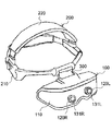
図1に、この実施形態におけるヘッドマウントディスプレイ(以下、「HMD」と称する。)の概観を示す。
HMDは、本体100と、本体100に接続された固定部材200とを備えている。固定部材200は、HMDをユーザの頭部に着脱自在に固定するためのものである。この実施形態における固定部材200は、HMDをユーザの頭部に固定するに際してユーザの頭部の周囲を囲む輪状部210と、HMDをユーザの頭部に固定するに際してユーザの頭部の上半分を頭頂部を通過しつつ左右にまたぐU字部220とを備えているが、HMDをユーザの頭部に着脱自在に固定することが可能であれば、固定部材200の構成はこの限りではない。例えば、固定部材200は、本体100の幅方向の両端の背面付近にその両端を接続された伸縮性を与えられたベルトとすることができる。
本体100と固定部材200とは、その両端で本体100及び固定部材200とヒンジ接続された板状の接続部材300で接続されている。接続部材300の存在により、固定部材200でHMDがユーザの頭部に固定された状態で、本体100をユーザの目の前方に位置させた状態と、ユーザの額の前に位置させた状態の2つの状態を採らせることができるようになる。ユーザの目の前方に本体100が位置した状態で、ユーザは後述する立体視用動画を見ることができる。また、ユーザは、立体視用動画を見る必要がない場合、或いは肉眼での視界を確保したい場合には、固定部材200を頭部に固定したまま、本体100を額の前に跳ね上げれば良い。
<< First Embodiment >>
FIG. 1 shows an overview of a head mounted display (hereinafter referred to as “HMD”) in this embodiment.
The HMD includes a
The
本体100は、中空とされたケース110を備えている。ケース110は、例えば樹脂製である。
ケース110の前面には、筒状の左右2つの鏡筒120R、120Lが取付けられている。鏡筒120Rは、本体100がユーザの目の前方に位置しているときに、略ユーザの右目の前に位置し、鏡筒120Lは、本体100がユーザの目の前方に位置しているときに、略ユーザの左目の前に位置するようになっている。両鏡筒120R、120Lは、後述する右目用動画と左目用動画とに適切な視差を与えるために図2に示したように、内側にやや傾けられている。
The
Two cylindrical right and left lens barrels 120R and 120L are attached to the front surface of the
鏡筒120R、120Lはケース110を前後に貫いている。鏡筒120R、120Lには、レンズである第1レンズ131R、131Lが取付けられている。第1レンズ131R、131Lは、これには限られないが拡大レンズである。ユーザの視野内にある対象物からの像光は、第1レンズ131R、131Lにて拡大されるようになっている。
鏡筒120R、120Lの基端側には、第1レンズ131R、131Lを通過した像光をケース110の幅方向の内側に向かって反射させる鏡である第1ミラー132R、132Lが設けられている。また、これには限られないが、ケース110の幅方向の略中央には、第1ミラー132R、132Lで反射された像光を、後述する撮像素子の撮像面に向けて反射させるための鏡である第2ミラー133R、133Lが設けられている。
第1レンズ131R、第1ミラー132R、第2ミラー133Rは、鏡筒120Rを通過した像光L1Rを、撮像素子の撮像面の所定の部分に結像させるためのものである。それが可能な限りにおいて、或いはそれを可能とするために必要なのであれば、鏡筒120Rを通過した像光L1Rの光路上に、レンズ、鏡、プリズム等の他の光学要素が存在していても構わない。同様に、第1レンズ131L、第1ミラー132L、第2ミラー133Lは、鏡筒120Lを通過した像光L1Lを、撮像素子の撮像面の所定の部分に結像させるためのものである。それが可能な限りにおいて、或いはそれを可能とするために必要なのであれば、鏡筒120Lを通過した像光L1Lの光路上に、レンズ、鏡、プリズム等の他の光学要素が存在していても構わない。なお、像光L1Rと、像光L1Lの結像する位置は、異なる位置となるようになっている。
より具体的には、像光L1Rは、撮像素子140の撮像面141の右半分(撮像素子を背後から(図2の下側から)見た場合の右半分。本願では撮像素子の左右の概念はすべてこれに倣っている。)のどこかに、像光L1Lは、撮像素子140の撮像面141の左半分のどこかに、それぞれ結像させられるようになっている。
The lens barrels 120R and 120L penetrate the
First mirrors 132 </ b> R and 132 </ b> L that are mirrors that reflect the image light that has passed through the first lenses 131 </ b> R and 131 </ b> L toward the inside in the width direction of the
The
More specifically, the image light L1R is the right half of the
ケース110の内部には、1つの撮像素子140が配置されている。撮像素子140の鏡筒120R、120L側には、撮像面141が設けられている。撮像面141はそこに結像した像光L1R、L1Lを撮像する面である。撮像素子140は、静止画像についてのデータであるフレームデータを連続して出力することにより、動画の撮像を行うことができるようなものとなっている。撮像素子140は、動画の撮像が可能となっている一般的なイメージセンサで良い。例えば、CCD(Charge-Coupled Device)、或いはCMOS(Complementary Metal Oxide Semiconductor)である。
撮像面141の大きさ形状は適宜選択可能であるが、この実施形態では、その縦横比が、9:16となるようになっている。
One
The size and shape of the
撮像素子140の撮像面141に像光L1Rと、像光L1Lとが導かれる範囲を図3に示す。
撮像面141は、物理的、構造的に分かれているわけではないが、右側の範囲である右撮像面141Rと、左側の範囲である左撮像面141Lとに、概念上分かれている。上述したように、像光L1Rと、像光L1Lとはそれぞれ、右撮像面141Rと、左撮像面141Lとに結像させられるようになっている。より詳細には、像光L1Rと、像光L1Lとはそれぞれ、右撮像面141Rの中心(CR)と、左撮像面141Lの中心(CL)に結像されるようになっている。
撮像面141に導かれた像光L1Rと、像光L1Lはともに、共に矩形である右撮像面141Rと、左撮像面141Lに略一致するようになっている(完全に一致するようになっていても勿論よい。)。これにより像光L1Rと、像光L1Lとはともに、右撮像面141Rと、左撮像面141Lの略全体(或いは全体)をカバーするようになっている。撮像面141に導かれた像光L1R及び像光L1Lの断面を共に矩形とするには、像光L1Rについては、第1ミラー132R、第2ミラー133Rの少なくとも一方において像光L1Rの周縁部の光を反射しないことにより、それを実現することができる。例えば、第2ミラー133Rの中心を像光L1Rの光軸と一致させるとともに、第2ミラー133Rの大きさを、撮像面141に導かれる像光L1Rが右撮像面141Rに略一致する程度に、第2ミラー133Rに至った像光L1Rの断面よりも予め小さくしておけば、撮像面141に導かれた像光L1Rの断面を矩形にするとともに、撮像面141に導かれる像光L1Rが右撮像面141Rに略一致するようにすることができる。像光L1Lにおいても同様である。
A range in which the image light L1R and the image light L1L are guided to the
Although the
Both the image light L1R and the image light L1L guided to the
撮像素子140は、フレームデータを連続して出力するための信号線151の一端と接続されている。信号線151は、その他端で、撮像素子140からフレームデータを受取る画像処理回路156と接続されている。画像処理回路156は、ハードウェア的に、或いはソフトウエア的に、後述する画像処理、より具体的には、各フレームデータの中から、像光L1Rによって生成されたデータと、像光L1Lによって生成されたデータをそれぞれ取出し、右目の画像である右目用動画用のフレームデータである右フレームデータと、左目の画像である左目用動画用のフレームデータである左フレームデータとを生成する処理を行うようになっている。なお、かかる処理については、後述する。
画像処理回路156は、右信号線152Rと、左信号線152Lとそれらの一端で接続されている。右フレームデータの連続である右目用動画のデータは右信号線152Rを介して、右信号線152Rの他端に接続されている右ディスプレイ160Rに出力されるようになっている。他方、左フレームデータの連続である左目用動画のデータは左信号線152Lを介して、左信号線152Lの他端に接続されている左ディスプレイ160Lに出力されるようになっている。右ディスプレイ160Rは、右目用動画のデータに基づいて右目用動画を表示するようになっている。左ディスプレイ160Lは、左目用動画のデータに基づいて左目用動画を表示するようになっている。右ディスプレイ160Rと、左ディスプレイ160Lとは、これには限られないが、この出願では同じディスプレイである。右ディスプレイ160Rと、左ディスプレイ160Lは、いずれも公知或いは周知のもので良く、例えば液晶ディスプレイであり、或いは有機ELディスプレイである。
なお、右ディスプレイ160Rと、左ディスプレイ160Lの画像が表示される面は、図2における下方である。
The
The
In addition, the surface on which the images of the
図2に示したように、本体100には、第2レンズ170R、170Lが取付けられている。
第2レンズ170Rは、右ディスプレイ160Rの背後にあり、本体100がユーザの眼前に位置している場合に、右ディスプレイ160Rからの像光L2Rをユーザの右目に導くようになっている。第2レンズ170Lは、左ディスプレイ160Lの背後にあり、本体100がユーザの眼前に位置している場合に、左ディスプレイ160Lからの像光L2Lをユーザの左目に導くようになっている。
第2レンズ170Rは、右ディスプレイ160Rに表示されている動画をユーザが見ることができるようにして、右ディスプレイ160Rからの像光L2Rをユーザの右目に導くものである。それが可能な限りにおいて、或いはそれを可能とするために必要なのであれば、像光L2Rの光路上に、レンズ、鏡、プリズム等の他の光学要素が存在していても構わない。
第2レンズ170Lは、左ディスプレイ160Lに表示されている動画をユーザが見ることができるようにして、左ディスプレイ160Lからの像光L2Lをユーザの左目に導くものである。それが可能な限りにおいて、或いはそれを可能とするために必要なのであれば、像光L2Lの光路上に、レンズ、鏡、プリズム等の他の光学要素が存在していても構わない。
As shown in FIG. 2, second lenses 170 </ b> R and 170 </ b> L are attached to the
The
The
The
次に、このHMDの使用方法及び動作について説明する。
このHMDを使用するには、ユーザは固定部材200を頭部に装着する。そして本体100を、ユーザの目の前方に位置させる。
Next, the usage method and operation | movement of this HMD are demonstrated.
To use this HMD, the user wears the fixing
ユーザは、見たい物の方に顔を向ける。
ユーザの鏡筒120Rと、鏡筒120Lの前方にあるその「物」からの像光L1R、及び像光L1Lは、図2に示したように、鏡筒120Rと、鏡筒120Lに向かい、第1レンズ131R、131Lを通過する。
像光L1R、及び像光L1Lは、第1レンズ131R、131Lを通過するときに拡大され、そして次に第1ミラー132R、132Lに向かう。像光L1R、及び像光L1Lは、第1ミラー132R、132Lでケース110の幅方向の内側に向かって反射させられ、第2ミラー133R、133Lに向かう。
第2ミラー133R、133Lで反射させられた像光L1R、及び像光L1Lは、撮像素子140の撮像面141に向かう。これには限られないが、上述したように、像光L1R、及び像光L1Lは、撮像面141上の右撮像面141Rの中心と、左撮像面141との中心とにそれぞれ結像させられるようになっている。
撮像面141が像光L1R、及び像光L1Lを捉えると、撮像素子140からはフレームデータが連続して出力される。よく知られているように、撮像面141には、図4に示したように、多数の走査線(フィールド)F1〜Fnが存在する。フレームデータは、1フレーム分のデータであるがそれは、走査線F1〜Fnからそれぞれ出力されたデータであるフィールドデータD1〜Dnの集合である。各フィールドデータD1〜Dnの終わりにはよく知られているように水平同期信号が追加され、各フレームデータの終わりにはよく知られているように垂直同期信号が追加される。これには限られないが、そのような極一般的なフレームデータが次々に、撮像素子140から出力される。なお、各走査線F1〜Fnは、右撮像面141Rと左撮像面141Lとで物理的に分断されているわけではなく、各走査線F1〜Fnからそれぞれ出力されたデータであるフィールドデータD1〜Dnも右撮像面141Rと、左撮像面141Lとの境界部分で分断されてはいない。
The user turns his face toward the object he wants to see.
The image light L1R and the image light L1L from the user's
The image light L1R and the image light L1L are enlarged when passing through the
The image light L1R and the image light L1L reflected by the
When the
フレームデータは信号線151を介して画像処理回路156に送られる。画像処理回路156は、画像処理を行う。ここで行われる画像処理は、少なくとも、各フレームデータの中から、像光L1Rによって生成されたデータと、像光L1Lによって生成されたデータをそれぞれ取出し(或いはそれらデータを分離し)、右目の画像である右目用動画用のフレームデータである右フレームデータと、左目の画像である左目用動画用のフレームデータである左フレームデータとを生成する処理を含んでいる。
各フレームデータの中から、像光L1Rによって生成されたデータと、像光L1Lによって生成されたデータをそれぞれ取出すには、各フレームデータを構成するフィールドデータD1〜Dnを前後半に二等分し、前半部分を右フレームデータを構成する右フィールドデータDR1〜DRnと、後半部分を左フレームデータを構成する左フィールドデータDL1〜DLnとすればよい。上述したように、各走査線F1〜Fnは、右撮像面141Rと左撮像面141Lとで物理的に分断されているわけではないが、それらのうち右撮像面141Rに位置するものが出力するデータは、フィールドデータD1〜Dnのうちの前半部分に対応し、それらのうち左撮像面141Lに位置するものが出力するデータは、フィールドデータD1〜Dnのうちの後半部分に対応するから、各フレームデータを構成するフィールドデータD1〜Dnを単に前後に二等分するだけで、各フレームデータを、像光L1Rによって生成されたデータと、像光L1Lによって生成されたデータとに分離したことになるのである。なお、各フィールドデータD1〜Dnを前後半に分けるには、例えば、各フィールドデータの中に含まれる、各素子が生成した信号の数を画像処理回路156で計数し、前後の信号の数が等しくなるようにすれば良い。
なお、像光L1Rと、像光L1Lが、右撮像面141Rと、左撮像面141Lの中心にそれぞれ結像しない場合、或いは、右撮像面141Rと、左撮像面141Lとが撮像面141を左右に二等分したものでない場合においても、各フィールドデータD1〜Dnを適当に分割することにより(フィールドデータによっては、0%と100%に分割され、事実上分割されないこともある。)、各フレームデータを、像光L1Rによって生成されたデータと、像光L1Lによって生成されたデータとに分離することができる。
そして、フィールドデータD1〜Dnの前半から得られた右フィールドデータDR1〜DRnを図5に示したように一纏めにして右フレームデータとし、フィールドデータD1〜Dnの後半から得られた左フィールドデータDL1〜DLnを図5に示したように一纏めにすると左フレームデータとなる。画像処理回路156は、これらにも、通常のビデオ信号と同様に、公知の水平同期信号と垂直同期信号を追加する。それにより、右フレームデータも、左フレームデータも、公知或いは周知のディスプレイにより普通に扱えるものとなる。
The frame data is sent to the
In order to extract the data generated by the image light L1R and the data generated by the image light L1L from each frame data, the field data D1 to Dn constituting each frame data are divided into two equal parts. The first half part may be the right field data DR1 to DRn constituting the right frame data, and the second half part may be the left field data DL1 to DLn constituting the left frame data. As described above, each of the scanning lines F1 to Fn is not physically divided between the
Note that when the image light L1R and the image light L1L are not focused on the centers of the
Then, the right field data DR1 to DRn obtained from the first half of the field data D1 to Dn are collected as right frame data as shown in FIG. 5, and the left field data DL1 obtained from the second half of the field data D1 to Dn is collected. When DLn is grouped as shown in FIG. 5, the left frame data is obtained. The
画像処理回路156は、右フレームデータの連続である右目用動画のデータを右信号線152Rを介して、右ディスプレイ160Rに出力する。同時に画像処理回路156は、左フレームデータの連続である左目用動画のデータを、左信号線152Lの他端に接続されている左ディスプレイ160Lに出力する。右ディスプレイ160Rは、右目用動画のデータに基づいて右目用動画を表示する。他方、左ディスプレイ160Lは、左目用動画のデータに基づいて左目用動画を表示する。
The
第2レンズ170Rは、右ディスプレイ160Rの背後にあり、本体100がユーザの眼前に位置している場合に、右ディスプレイ160Rからの像光L2Rをユーザの右目に導くようになっている。第2レンズ170Lは、左ディスプレイ160Lの背後にあり、本体100がユーザの眼前に位置している場合に、左ディスプレイ160Lからの像光L2Lをユーザの左目に導くようになっている。
第2レンズ170Rは、右ディスプレイ160Rに表示されている動画をユーザが見ることができるようにして、右ディスプレイ160Rからの像光L2Rをユーザの右目に導く。
同時に、第2レンズ170Lは、左ディスプレイ160Lに表示されている動画をユーザが見ることができるようにして、左ディスプレイ160Lからの像光L2Lをユーザの左目に導く。
右目で像光L2Rを、左目で像光L2Lを見たユーザは、立体視を行うことができる。ユーザは、かかる立体視を、略実時間で行うことができる。ユーザが立体視で見ることのできる動画は、この実施形態の場合であれば、第1レンズ131R、131Lの存在により、ユーザが肉眼で物を見た場合とは異なるものとなる。
The
The
At the same time, the
A user who has viewed the image light L2R with the right eye and the image light L2L with the left eye can perform stereoscopic viewing. The user can perform such stereoscopic viewing in substantially real time. In the case of this embodiment, the moving image that can be viewed by the user is different from the case where the user views the object with the naked eye due to the presence of the
一時的に立体視を行う必要がなくなったらユーザは、本体100を額の前に跳ね上げ、また完全に立体視を行う必要がなくなったのであれば、固定部材200を頭部から外す。
When it is no longer necessary to perform stereoscopic viewing temporarily, the user flips up the
≪第2実施形態≫
次に、本願発明の第2実施形態について説明する。
第2実施形態は、カメラである。このカメラは、立体視用の動画データを生成する装置である。
<< Second Embodiment >>
Next, a second embodiment of the present invention will be described.
The second embodiment is a camera. This camera is a device that generates moving image data for stereoscopic viewing.
立体視用動画データを生成するための第2実施形態のカメラは、そのような目的で用いられている公知のカメラと同様、いわゆるステレオカメラである。
そして、このカメラの構成は、第1実施形態のHMDの構成を、右目用動画のデータと左目用動画のデータの生成を行うまでの機構を撮像側の機構と呼び、右目用動画と左目用動画とを右ディスプレイ160Rと、左ディスプレイ160Lに表示してユーザの目に見せるための機構を表示側の機構と呼ぶのであれば、第1実施形態のHMDの撮像側の機構と概ね同一の構成を有している。
The camera of the second embodiment for generating stereoscopic video data is a so-called stereo camera, similar to a known camera used for such a purpose.
In the configuration of this camera, the mechanism until the generation of the right-eye moving image data and the left-eye moving image data is referred to as the imaging-side mechanism in the HMD configuration of the first embodiment, and the right-eye moving image and the left-eye moving image are generated. If the mechanism for displaying the moving image on the
カメラは、ケース110を備えている。ただし、このケース110は、第1実施形態の場合に存在した固定部材200と接続されている必要はない。固定部材200と接続してヘッドマウントカメラとしてこのカメラを用いることも勿論可能ではあるが、例えば所定の台の上に載置して、或いは周知の三脚の上部に接続した状態でこのカメラを用いることが前提なのであれば、固定部材200は不要である。
ケース110には2つの鏡筒120R、120Lが設けられており、それらには、第1レンズ131R、131Lが取付けられている。もっとも、第1レンズ131R、131Lは、像光L1R、及び像光L1Lを拡大するものでなくても良い。ケース110の内部には、第1ミラー132R、132Lと、第2ミラー133R、133Lがあり、また、撮像素子140が存在している。撮像素子140は、右撮像面と左撮像面とに概念的に分割された撮像面141を備えている。
ここまでは、特に断りのない点については、それらの機能を含めて、第1実施形態の場合と変わりがない。
The camera includes a
The
Up to this point, there are no particular differences from the case of the first embodiment, including those functions, unless otherwise noted.
第2実施形態のカメラが第1実施形態のヘッドマウントと異なるのは、事実上、筐体の中に第2画像処理回路180と、記録媒体190が存在するという点である。
第2画像処理回路180は、右信号線152Rと左信号線152Lを介して、画像処理回路156と接続されている。画像処理回路156は、第1実施形態の場合と同様に、右フレームデータの連続である右目用動画のデータを右信号線152Rを介して出力し、左フレームデータの連続である左目用動画のデータを、左信号線152Lを介して出力するようになっている。右目用動画のデータと、左目用動画のデータとは、それらがそれぞれ右ディスプレイ160Rと、左ディスプレイ160Lで受け取られた第1実施形態の場合と異なり、第2画像処理回路180に受け取られるようになっている。
第2画像処理回路180は、右目用動画のデータ及び左目用動画のデータに対して、必要に応じて画像処理を行うようになっている。必要がなければ第2画像処理回路180は、右目用動画のデータ及び左目用動画のデータをそのまま通過させる。
The camera of the second embodiment is different from the head mount of the first embodiment in that the second
The second
The second
第2画像処理回路180で画像処理が必要な場合において行われる画像処理は、もっぱら、画像処理回路156が生成した右目用動画のデータと、左目用動画のデータとを用いてユーザに立体視を行わせる装置である立体視用動画表示装置が、1つのディスプレイを備えるときにおいて、右目用動画のデータと、左目用動画のデータという2つのデータから、かかる1つのディスプレイに表示させる1つの動画のデータを生成するというものである。
例えば、立体視用動画表示装置が1つのディスプレイで、時分割される立体視用の動画を表示する場合には、立体視用の動画のデータは、1フレーム毎に交互に右目用動画を構成するフレームと左目用動画を構成するフレームが連続していくものとなる。この場合には、第2画像処理回路180は、右目用動画のデータの1フレーム目、左目用動画のデータの2フレーム目、右目用動画のデータの3フレーム目、左目用動画のデータの4フレーム目…、というように、右目用動画に連続して含まれるフレームと、左目用動画に連続して含まれるフレームとを、それぞれのフレームからフレームを一つ飛ばしに落として行きつつ、交互に連続させて、立体視用の動画のデータを生成する。
また、立体視用動画表示装置が1つのディスプレイで視差分割される立体視用の動画を表示する場合には、立体視用の動画のデータにおける各フレームは、各フレームの視差によって分割される右目で見るべき範囲に右目用動画の画像が、左目で見るべき範囲に左目用動画の画像が、それぞれ配置されたものとなる。この場合には、第2画像処理回路180は、右目用動画のデータと左目用動画のデータから、同じ順番のフレームの画像同士を適切に混合して新たなフレームデータを順に生成することにより立体視用の動画のデータを生成する。
The image processing performed when image processing is necessary in the second
For example, when a stereoscopic video display device displays a time-divided stereoscopic video on a single display, the stereoscopic video data alternately forms a right-eye video for each frame. The frames constituting the moving image for the left eye and the left eye moving image are continuous. In this case, the second
In addition, when the stereoscopic video display device displays a stereoscopic video that is parallax-divided on one display, each frame in the stereoscopic video data is divided by the right eye divided by the parallax of each frame. The moving image for the right eye is arranged in the range to be viewed with the left eye, and the moving image for the left eye is arranged in the range to be viewed with the left eye. In this case, the second
第2画像処理回路180は、右出力線181Rと、左出力線181Lとに接続されており、また、右接続線182Rと、左接続線182Lに接続されている。右接続線182Rと、左接続線182Lは、記録媒体190に接続されている。記録媒体190はデータの記録を行えるものであり、公知、周知のもので良い。記録媒体190は、カメラに対して固定されていてもよく、カメラに対して着脱自在とされていてもよい。前者の例としては例えばハードディスクを挙げることができ、後者の例としては、DVDディスクや、USBメモリを挙げることができる。
第2画像処理回路180が右目用動画のデータと左目用動画のデータに対して何らの処理も行わなかった場合には、それらデータはそのまま右出力線181Rと、左出力線181Lから外部に出力されるか、或いは右接続線182Rと、左接続線182Lから記録媒体190に送られる。記録媒体190に送られた右目用動画のデータと左目用動画のデータは、記録媒体190に記録される。右出力線181Rと、左出力線181Lから外部に出力された右目用動画のデータと左目用動画のデータは、外部の装置に送られて、例えば、第2画像処理回路180で行われたのと同じように、1つのディスプレイでの立体視を実現するための立体視用の動画データを生成するために用いられる。記録媒体190に記録された右目用動画のデータと左目用動画のデータは、必要なときに、第2画像処理回路180と、右出力線181R及び左出力線181Lと、を介して外部に出力され、上述の場合と同様に利用される。また、記録媒体190がカメラに対して着脱自在になっているのであれば、カメラから取外した記録媒体190に記録されたデータを他の装置に読み込ませることによって、そのデータを上述の場合と同様に利用することができる。
他方、第2画像処理回路180で上述のような処理を行った場合においては、処理されたデータは、例えば右出力線181Rを介して外部の装置に出力され、或いは右接続線182Rを介して記録媒体190に送られ、記録媒体190に記録される。第2画像処理回路180で生成されたデータは一列のデータである場合には、右出力線181Rと左出力線181Lという2本の出力線は不要であり、また右接続線182Rと、左接続線182Lという2本の接続線は不要である。
第2画像処理回路180で画像処理を行うか否か、また画像処理が行われた、或いは行われなかったデータの出力先をどこにするのか、或いは記録媒体190に記録されたデータをいつ出力するのかは、例えば、カメラのケース110に設けた、テンキーその他の図示を省略の入力装置からの入力によって決定可能とすることができる。
The second
When the second
On the other hand, when the above-described processing is performed by the second
Whether to perform image processing in the second
100 本体
110 ケース
120 鏡筒
131R 第1レンズ
131L 第1レンズ
132R 第1ミラー
132L 第1ミラー
133R 第2ミラー
133L 第2ミラー
140 撮像素子
141 撮像面
141R 右撮像面
141L 左撮像面
156 画像処理回路
160R 右ディスプレイ
160L 左ディスプレイ
170R 第2レンズ
170L 第2レンズ
180 第2画像処理回路
190 記録媒体
200 固定部材
300 接続部材
L1R 像光
L1L 像光
L2R 像光
L2L 像光
DESCRIPTION OF
Claims (8)
前記撮像素子に右目用の画像である右目用動画の像光である右像光を導く右撮像光学系と、
前記撮像素子に左目用の画像である左目用動画の像光である左像光を導く左撮像光学系と、
を備えてなるとともに、
前記右像光と、前記左像光とは、前記撮像素子の前記撮像面の異なる部位に結像させられるようになっており、前記撮像素子は、前記右像光と、前記左像光とによる動画データを出力するようになっている、
立体視用動画データ生成装置。 By continuously outputting frame data, which is data about a still image based on the image light imaged on the imaging surface, having an imaging surface for imaging the image light imaged there. One image sensor capable of capturing a moving image;
A right imaging optical system for guiding right image light, which is image light of a moving image for right eye, which is an image for right eye, to the imaging element;
A left imaging optical system that guides left image light that is image light of a left-eye moving image that is an image for the left eye to the imaging element;
As well as
The right image light and the left image light are formed on different parts of the imaging surface of the imaging device, and the imaging device includes the right image light, the left image light, and the left image light. To output video data by
Stereoscopic moving image data generation device.
前記画像処理手段は、各フレームデータの中から、前記右像光によって生成されたデータと、前記左像光によって生成されたデータをそれぞれ取出し、右目画像用のフレームデータである右フレームデータと、左目画像用のフレームデータである左フレームデータとを生成することにより、立体視における右目用動画のデータと、左目用動画のデータとを別々に出力できるようになっている、
請求項1記載の立体視用動画データ生成装置。 Comprising image processing means adapted to perform image processing on the frame data output by the image sensor;
The image processing means takes out data generated by the right image light and data generated by the left image light from each frame data, and right frame data that is frame data for the right eye image, By generating left frame data that is frame data for the left eye image, right eye moving image data and left eye moving image data in stereoscopic view can be output separately.
The stereoscopic video data generating device according to claim 1.
請求項1又は2記載の立体視用動画データ生成装置。 The right image light and the left image light are respectively formed on the right region and the left region when the imaging surface is divided into right and left, respectively.
The stereoscopic moving image data generation device according to claim 1 or 2.
請求項3記載の立体視用動画データ生成装置。 The right image light and the left image light are respectively imaged at the center of the right region and the center of the left region when the imaging surface is divided into right and left.
The stereoscopic video data generating device according to claim 3.
請求項4記載の立体視用動画データ生成装置。 The image processing means collects data for specifying a scanning line of a portion generated by a pixel in a region on the right side of the imaging surface among each scanning line included in each of the frame data, and obtains right frame data, Among the scanning lines included in each frame data, data specifying the scanning lines of the portion generated by the pixels in the left region of the imaging surface is collected, and left frame data is generated respectively. ,
The stereoscopic video data generating device according to claim 4.
前記画像処理手段から順次出力される前記右フレームデータからなる前記右目用動画のデータを受取り、ユーザの右目に前記右目用動画のデータに基づく動画である右目用動画の像光を出力する右ディスプレイと、
前記画像処理手段から順次出力される前記左フレームデータからなる前記左目用動画のデータを受取り、ユーザの左目に前記左目用動画のデータに基づく動画である左目用動画の像光を出力する左ディスプレイと、
を有することにより、前記撮像素子で撮像された前記右像光に基づく右目用動画と、前記撮像素子で撮像された前記左像光に基づく左目用動画とを、略実時間でユーザの右目と左目に導くことができるようになっている、
立体視用動画表示装置。 A stereoscopic video display device comprising the stereoscopic video data generation device according to any one of claims 1 to 5,
A right display that receives the right eye moving image data composed of the right frame data sequentially output from the image processing means, and outputs right eye moving image light that is a moving image based on the right eye moving image data to the user's right eye When,
A left display that receives the left-eye moving image data composed of the left frame data sequentially output from the image processing means, and outputs image light of the left-eye moving image that is a moving image based on the left-eye moving image data to the user's left eye When,
A right-eye moving image based on the right image light imaged by the image sensor and a left-eye moving image based on the left image light imaged by the image sensor, and the user's right eye in substantially real time. Can be led to the left eye,
Stereoscopic video display device.
ヘッドマウントディスプレイとされた、
請求項6記載の立体視用動画表示装置。 A main body including the stereoscopic video data generation device, the right display, and the left display; and a fixing unit that detachably fixes the main body to a user's head,
Head mounted display,
The moving image display device for stereoscopic viewing according to claim 6.
前記撮像素子に右目用の画像である右目用動画の像光である右像光を導く右撮像光学系と、
前記撮像素子に左目用の画像である左目用動画の像光である左像光を導く左撮像光学系と、
前記撮像素子によって出力されたフレームデータに対して画像処理を行うことができるようになっている、画像処理手段と、
を備えており、
前記右像光と、前記左像光とは、前記撮像素子の前記撮像面の異なる部位に結像させられるようになっている、
立体視用動画データ生成装置にて実行される方法であって、
前記画像処理手段が、
各フレームデータの中から、前記右像光によって生成されたデータと、前記左像光によって生成されたデータをそれぞれ取出す過程、
右目画像用のフレームデータである右フレームデータと、左目画像用のフレームデータである左フレームデータとを生成することにより、立体視における右目用動画のデータと、左目用動画のデータとを別々に出力する過程、
を含む方法。 By continuously outputting frame data, which is data about a still image based on the image light imaged on the imaging surface, having an imaging surface for imaging the image light imaged there. One image sensor capable of capturing a moving image;
A right imaging optical system for guiding right image light, which is image light of a moving image for right eye, which is an image for right eye, to the imaging element;
A left imaging optical system that guides left image light that is image light of a left-eye moving image that is an image for the left eye to the imaging element;
Image processing means adapted to perform image processing on the frame data output by the imaging device;
With
The right image light and the left image light are adapted to be imaged on different parts of the imaging surface of the imaging element.
A method executed by the stereoscopic video data generation device,
The image processing means
A process of taking out the data generated by the right image light and the data generated by the left image light from each frame data,
By generating right frame data that is frame data for the right eye image and left frame data that is frame data for the left eye image, the data for the right eye moving image and the data for the left eye moving image in stereoscopic view are separated. Output process,
Including methods.
Priority Applications (1)
| Application Number | Priority Date | Filing Date | Title |
|---|---|---|---|
| JP2015081942A JP2016201742A (en) | 2015-04-13 | 2015-04-13 | Moving image data for stereoscopic vision generation device, method executed thereby, and moving image display device for stereoscopic vision |
Applications Claiming Priority (1)
| Application Number | Priority Date | Filing Date | Title |
|---|---|---|---|
| JP2015081942A JP2016201742A (en) | 2015-04-13 | 2015-04-13 | Moving image data for stereoscopic vision generation device, method executed thereby, and moving image display device for stereoscopic vision |
Publications (1)
| Publication Number | Publication Date |
|---|---|
| JP2016201742A true JP2016201742A (en) | 2016-12-01 |
Family
ID=57424730
Family Applications (1)
| Application Number | Title | Priority Date | Filing Date |
|---|---|---|---|
| JP2015081942A Pending JP2016201742A (en) | 2015-04-13 | 2015-04-13 | Moving image data for stereoscopic vision generation device, method executed thereby, and moving image display device for stereoscopic vision |
Country Status (1)
| Country | Link |
|---|---|
| JP (1) | JP2016201742A (en) |
Citations (7)
| Publication number | Priority date | Publication date | Assignee | Title |
|---|---|---|---|---|
| JPS6170839U (en) * | 1984-10-17 | 1986-05-14 | ||
| JPH0870474A (en) * | 1994-08-29 | 1996-03-12 | Sanyo Electric Co Ltd | Stereoscopic image pickup unit and stereoscopic image recording and reproducing device |
| JPH08149515A (en) * | 1994-11-18 | 1996-06-07 | Sanyo Electric Co Ltd | Stereoscopic image pickup device |
| JP2004260787A (en) * | 2002-09-09 | 2004-09-16 | Rohm Co Ltd | Image sensor module |
| JP2011247966A (en) * | 2010-05-24 | 2011-12-08 | Olympus Imaging Corp | Imaging apparatus |
| JP2013132026A (en) * | 2011-12-22 | 2013-07-04 | Canon Inc | Information processing apparatus |
| JP2013222177A (en) * | 2012-04-19 | 2013-10-28 | Canon Inc | Stereoscopic video photographing optical system and stereoscopic video photographing device |
-
2015
- 2015-04-13 JP JP2015081942A patent/JP2016201742A/en active Pending
Patent Citations (7)
| Publication number | Priority date | Publication date | Assignee | Title |
|---|---|---|---|---|
| JPS6170839U (en) * | 1984-10-17 | 1986-05-14 | ||
| JPH0870474A (en) * | 1994-08-29 | 1996-03-12 | Sanyo Electric Co Ltd | Stereoscopic image pickup unit and stereoscopic image recording and reproducing device |
| JPH08149515A (en) * | 1994-11-18 | 1996-06-07 | Sanyo Electric Co Ltd | Stereoscopic image pickup device |
| JP2004260787A (en) * | 2002-09-09 | 2004-09-16 | Rohm Co Ltd | Image sensor module |
| JP2011247966A (en) * | 2010-05-24 | 2011-12-08 | Olympus Imaging Corp | Imaging apparatus |
| JP2013132026A (en) * | 2011-12-22 | 2013-07-04 | Canon Inc | Information processing apparatus |
| JP2013222177A (en) * | 2012-04-19 | 2013-10-28 | Canon Inc | Stereoscopic video photographing optical system and stereoscopic video photographing device |
Similar Documents
| Publication | Publication Date | Title |
|---|---|---|
| CN101836432A (en) | Imaging device and image recording and playback system | |
| JPS59500298A (en) | 3D image television system | |
| JP2006033228A (en) | Picture imaging apparatus | |
| KR20110114620A (en) | Stereoscopic imaging apparatus and method | |
| CN101995758A (en) | Imaging device and video recording/reproducing system | |
| CN107111147A (en) | Stereos copic viewing device | |
| US20150301313A1 (en) | Stereoscopic lens for digital cameras | |
| CN103329549B (en) | Dimensional video processor, stereoscopic imaging apparatus and three-dimensional video-frequency processing method | |
| CN103339948B (en) | 3D video playing device, 3D imaging device, and 3D video playing method | |
| JP3676916B2 (en) | Stereoscopic imaging device and stereoscopic display device | |
| JP2018152748A (en) | Imaging/display device of stereoscopic image and head mount device | |
| JP2011053564A (en) | Display device and imaging device | |
| JPS63244011A (en) | Electronic endoscope | |
| JPH11187425A (en) | Stereoscopic video system and method | |
| JP2004144873A (en) | Picture display device and picture display method | |
| JP2016201742A (en) | Moving image data for stereoscopic vision generation device, method executed thereby, and moving image display device for stereoscopic vision | |
| JP5627930B2 (en) | 3D image data generation method | |
| JP3235441U (en) | Encode the image of one camera of one image sensor into all existing 3D formats | |
| JP2006129225A (en) | Stereoscopic video image display device and method | |
| KR100401703B1 (en) | Photographing apparatus for stereo image | |
| JP5551517B2 (en) | Imaging device | |
| JP4353001B2 (en) | 3D imaging adapter | |
| US20060127055A1 (en) | 3-Dimensional video recording/reproduction device | |
| JP2014045392A (en) | Stereoscopic image receiver | |
| JP7202449B2 (en) | Optical Arrangement for Generating Virtual Reality Stereoscopic Images |
Legal Events
| Date | Code | Title | Description |
|---|---|---|---|
| A621 | Written request for application examination |
Free format text: JAPANESE INTERMEDIATE CODE: A621 Effective date: 20180413 |
|
| A977 | Report on retrieval |
Free format text: JAPANESE INTERMEDIATE CODE: A971007 Effective date: 20190128 |
|
| A131 | Notification of reasons for refusal |
Free format text: JAPANESE INTERMEDIATE CODE: A131 Effective date: 20190205 |
|
| A601 | Written request for extension of time |
Free format text: JAPANESE INTERMEDIATE CODE: A601 Effective date: 20190408 |
|
| A521 | Request for written amendment filed |
Free format text: JAPANESE INTERMEDIATE CODE: A523 Effective date: 20190606 |
|
| A02 | Decision of refusal |
Free format text: JAPANESE INTERMEDIATE CODE: A02 Effective date: 20190910 |