JP2004144873A - Picture display device and picture display method - Google Patents
Picture display device and picture display method Download PDFInfo
- Publication number
- JP2004144873A JP2004144873A JP2002307938A JP2002307938A JP2004144873A JP 2004144873 A JP2004144873 A JP 2004144873A JP 2002307938 A JP2002307938 A JP 2002307938A JP 2002307938 A JP2002307938 A JP 2002307938A JP 2004144873 A JP2004144873 A JP 2004144873A
- Authority
- JP
- Japan
- Prior art keywords
- image
- lens
- image display
- display device
- dimensional
- Prior art date
- Legal status (The legal status is an assumption and is not a legal conclusion. Google has not performed a legal analysis and makes no representation as to the accuracy of the status listed.)
- Pending
Links
Images


Abstract
Description
【0001】
【発明の属する技術分野】
本発明は、三次元画像表示を含めた画像表示が可能な画像表示装置及び画像表示方法の技術分野に属する。
【0002】
【従来の技術】
従来より、表示装置としてブラウン管、EL、液晶、プラズマ等の手段を用いたものがある。それらは表示装置の表示面に表示された画像を直接二次元画像として見る形態のものである。また一方ではこれら表示装置を用い画像を立体として視覚できる三次元画像を表示する三次元画像表示装置があり、種々の形態が提案され実施されてきている。この三次元画像は例えばエンタテイメント、デザイン、医療等の分野で活用され、更なる効果的な三次元画像表示手段が望まれているところである。
【0003】
三次元画像表示装置の一例として、例えば液晶シャッタ眼鏡方式が良く知られている。この方式はカメラで三次元物体を異なる方向から撮影し、得られた視差情報を含む画像データを合成して1つの画像信号に合成し、二次元表示装置に入力し表示する。観察者は液晶シャッタ眼鏡をかけ、例えば奇数フィールド時に右目用の液晶シャッタを光透過状態とし左目用の液晶シャッタを光遮断状態とし、一方、偶フィールド時に左目用の液晶シャッタが光透過状態とし右目用の液晶シャッタを光遮断状態とする。このとき、奇数フィールドに右目用の画像を、偶フィールドに左目用の画像を同期して表示することで右目用、左目用の視差を含む画像を夫々の目で見ることにより立体像を得るものである。
【0004】
また、観察者の視線に対して前後方向に複数の表示手段を設け、夫々に表示される物体の輝度から三次元画像を視覚する形態の三次元表示装置がある。
【0005】
【発明が解決しようとする課題】
しかしながら、これらの方式には観察者に装着する装置や表示する画像の三次元表示用の信号処理を必要とし、或いは複数の表示装置を備えたり、または表示装置自体が複雑な構成になるものであった。また、視差を使う方法による三次元画像を見る場合、眼の疲労が大きいと言われている。
【0006】
従って本発明は上記問題点に鑑みなされたものであり、二次元表示装置の画面に表示される画像を所定位置に結像させ、観察者が二次元画像は勿論、三次元画像表示を含めた画像を視覚することが可能な比較的簡単な構成で効果的な画像表示装置及び画像表示方法を提供することを課題とする。
【0007】
【課題を解決するための手段】
上記課題を解決するために請求項1に記載の発明は、二次元画像表示手段と、前記二次元画像表示手段の表示面前方に、当該表示面と平行に設けられた複数のレンズからなる画像結像手段と、前記二次元画像表示手段に入力される画像信号を生成する画像信号生成手段とを備える画像表示装置であることを特徴とする。
【0008】
また、請求項2に記載の発明は、二次元画像表示手段と、前記二次元画像表示手段の表示面前方に、当該表示面と平行に設けられた複数のレンズからなり、且つ、夫々のレンズは複数の焦点距離のうちの何れか1つの焦点距離を有する画像結像手段と、前記レンズの夫々の焦点距離に対応し、前記二次元画像表示手段に表示される画像信号を生成する画像信号生成手段とを備える画像表示装置であることを特徴とする。
【0009】
また、請求項20に記載の発明は、二次元画像表示手段の表示面の前方に、当該表示面と平行に複数のレンズからなる画像結像手段を設け、前記二次元画像表示手段に画像信号生成手段により生成された画像信号を入力して画像を表示し、当該表示された画像を、前記画像結像手段により前記表示面とは異なる位置に結像させる画像表示方法であることを特徴とする。
【0010】
更に、請求項21に記載の発明は、二次元画像表示手段の表示面の前方に、当該表示面と平行に複数のレンズからなり、且つ、夫々のレンズは複数の焦点距離のうちの何れか1つの焦点距離を有する画像結像手段を設け、前記二次元画像表示手段に画像信号生成手段により前記レンズの夫々の焦点距離に対応して生成された画像信号を入力して画像を表示し、当該表示された画像を、前記画像結像手段により前記表示面とは異なる位置に結像させる画像表示方法であることを特徴とする。
【0011】
【発明の実施の形態】
本発明の実施の形態について以下に説明する。
【0012】
本発明の実施の形態に係わる画像表示装置は、二次元画像表示手段と、前記二次元画像表示手段の表示面前方に、当該表示面と平行に設けられた複数のレンズからなる画像結像手段と、前記二次元画像表示手段に入力される画像信号を生成する画像信号生成手段とを備える。
【0013】
本発明の画像表示装置によれば、二次元画像表示手段の表示面の前方に置かれた画像結像手段により、表示面に表示される画像は表示面とは異なる位置に結像される。その結像位置は画像結像手段のレンズの焦点距離と、レンズと表示面との距離の関係に基づいて決定され、表示面から前方、或いは後方に結像される。観察者はこの結像された画像を見ることにより、表示面から前方、または後方に表示画像を視覚することができる。画像表示装置は、その表示面が平面であることが好ましい。また、画像結像手段と二次元画像表示手段との配置により、表示面の大きさよりも大きく、或いは小さく結像させることもできる。
【0014】
本発明の実施の形態に係わる画像表示装置は、二次元画像表示手段と、前記二次元画像表示手段の表示面前方に、当該表示面と平行に設けられた複数のレンズからなり、且つ、夫々のレンズは複数の焦点距離のうちの何れか1つの焦点距離を有する画像結像手段と、前記レンズの夫々の焦点距離に対応し、前記二次元画像表示手段に表示される画像信号を生成する画像信号生成手段とを備える。
【0015】
本発明の画像表示装置によれば、二次元画像表示手段の表示面の前方に置かれた画像結像手段により、表示面に表示される画像は表示面とは異なる、夫々のレンズの焦点距離と、レンズと表示面との距離の関係に基づいた位置に結像され、観察者は表示面から前方に、または後方に三次元画像として視覚することができる。画像信号生成手段により、夫々のレンズに対応した画像信号が生成され、表示される。画像表示装置は、その表示面が平面であることが好ましい。また、画像結像手段と二次元画像表示手段との配置により、表示面の大きさよりも大きく、或いは小さく結像させることもできる。更に多くの焦点距離の異なるレンズを配置することで、多くの結像面を設定することができ、より滑らかな三次元画像を視覚することができる。
【0016】
本発明の実施の形態に係わる画像表示装置の一態様として、前記画像結像手段は複数のレンズアレイを重ね合わせて構成される。
【0017】
この態様によれば、焦点距離の異なるレンズアレイや所定の画素に対してのみレンズを備えるレンズアレイが用いられる。また、レンズを設ける部分と設けない部分を同一のサイズで等間隔に配置したレンズアレイでは、2枚のレンズアレイを、レンズのある部分とない部分とを重ね合わせ、表示面から夫々所定の距離に配置することで2つの結像面を得ることができる。同一のレンズアレイを用いるので安価に光学系が構成される。また、組み合わせる2つのレンズアレイの夫々のレンズの焦点距離は異なるものであっても良い。
【0018】
本発明の実施の形態に係わる画像表示装置の他の態様として、前記画像結像手段は、当該画像結像手段による前記二次元画像表示手段の画像が、前記二次元画像表示手段の表示面の前方に結像される位置に設定される構成とする。
【0019】
また、前記画像結像手段は、当該画像結像手段による前記二次元画像表示手段の画像が、前記二次元画像表示手段の表示面の後方に結像される位置に設定される構成とする。
【0020】
この態様によれば、レンズの焦点距離と、レンズと表示面との距離の関係に基づいて、二次元画像表示手段の表示画像の結像位置を、表示面の前方、又は後方に設定することができる。観察者はこの結像画像を見ることで、表示面の前方、又は後方に三次元画像を視覚することができる。
【0021】
本発明の実施の形態に係わる画像表示装置の他の態様として、前記レンズは非球面レンズ、フレネルレンズ、分布屈折率レンズの何れも用いることが可能である。
【0022】
この態様によれば、装置の使用形態、条件等に基づいてレンズの形態を選択することができる。また、レンズは凸レンズ、凹レンズ、或いはフラットな形状のものであっても良い。
【0023】
本発明の実施の形態に係わる画像表示装置の他の態様として、前記レンズと前記二次元画像表示手段の間に所定の屈折率を有する部材を挿入する。
【0024】
この態様によれば、レンズと二次元画像表示手段の表示面との間に屈折率の高い透明部材を挿入することで、光学経路が短縮され、装置の小型化、薄型化が図れる。
【0025】
尚、小型化或いは薄型化のためには、レンズと二次元画像表示手段との間の距離を、レンズ自体で短くすることが好ましいが、これが困難な場合に、本態様を用いることによる効果が大きくなる。
【0026】
本発明の実施の形態に係わる画像表示装置の他の態様として、前記レンズと前記二次元画像表示手段の間に、当該レンズ間を光学的に分離する分離手段を設ける。
【0027】
この態様によれば、隣接する画素や周囲からの光を遮断することができるので、結像する画像の品位が向上する。尚、各レンズ自体が隣の画素や周囲からの光の影響が無いレンズであることが好ましいが、これが困難な場合、本形態を用いることで効果が大きい。
【0028】
本発明の実施の形態に係わる画像表示装置の他の態様として、前記二次元画像表示手段はブラウン管表示手段、液晶表示手段、EL表示手段、プラズマ表示手段の何れも用いることが可能である。
【0029】
この態様によれば、二次元画像表示手段として特に表示面が平坦であることが好適であり、ブラウン管表示手段、液晶表示手段、EL表示手段、プラズマ表示手段等による二次元画像表示手段を画像表示装置の使用形態、条件等に基づいて選択できる。
【0030】
本発明の実施の形態に係わる画像表示装置の他の態様として、前記レンズは前記二次元画像表示手段の画素の夫々に対応して設けられる。
【0031】
この態様によれば、レンズは二次元画像表示手段の画素の夫々に対応しても設けられるので、全ての画素について明るさや結像の品位が同じレベルとなり、品位の高い像を得ることができる。
【0032】
本発明の実施の形態に係わる画像表示装置の他の態様として、前記レンズは前記二次元画像表示手段の所定の画素ブロックに対応して設けられる。
【0033】
この態様によれば、二次元画像表示手段の複数の画素に一つのレンズを対応させるので、レンズアレイの構成が簡単になる。
【0034】
本発明の実施の形態に係わる画像表示装置の他の態様として、前記レンズは前記二次元画像表示手段の水平ラインに対応して設けられる。
【0035】
この態様によれば、二次元画像表示手段の水平ラインごとに同一の焦点距離を有するレンズを対応させるので、同一水平ラインの画素は同一結像面に結像することになる。従って同一水平ラインの画素は同一結像面の画像を表示するので、二次元画像表示手段に入力する画像の作成が容易になる。
【0036】
本発明の実施の形態に係わる画像表示装置の他の態様として、前記レンズは前記二次元画像表示手段の垂直ラインに対応して設けられる。
【0037】
この態様によれば、二次元画像表示手段の垂直ラインごとに同一の焦点距離を有するレンズを対応させるので、同一垂直ラインの画素は同一結像面に結像することになる。従って同一垂直ラインの画素は同一結像面の画像を表示するので、二次元画像表示手段に入力する画像の作成が容易になる。
【0038】
本発明の実施の形態に係わる画像表示装置の他の態様として、前記画像信号生成手段は、前記表示面に表示される画像に付加される輝度情報及び色彩情報及び大きさに関する情報及びフォーカスに関する情報のうち、少なくとも1つの情報を備える。
【0039】
この態様によれば、結像される位置に応じて、より効果的な立体像を得ることができる。即ち、表示内容に従い、輝度、色彩、大きさ、フォーカス感等に変化を付けて、これらの要素を組み合わせて奥行感、立体感をより感じさせる相乗的効果が得られる。例えば、輝度に関しては手前は明るく、奥は暗く陰影を付け、また、大きさに関しては手前は大きく、奥は小さくする。色彩に関しては黄色は手前に見え、青は奥に感じ、また、フォーカス感、即ちピントが合っている場合は手前に感じ、合っていない場合は奥に感じる。このように表示面に表示される画像に、輝度、色彩、大きさ、フォーカス感等の1つ、或いは複数の情報を結像させる位置に従って付加しておき、表示するときにこれらの情報に従って画像変換して出力させる。またはそれらの情報に基づいて変換した画像を蓄積しておいて、順次、出力するようにしても良い。上述した手法を導入することでより効果的な立体像が得られる。
【0040】
本発明の実施の形態に係わる画像表示方法は、二次元画像表示手段の表示面の前方に、当該表示面と平行に複数のレンズからなる画像結像手段を設け、前記二次元画像表示手段に画像信号生成手段により生成された画像信号を入力して画像を表示し、当該表示された画像を、前記画像結像手段により前記表示面とは異なる位置に結像させる方法である。
【0041】
本発明の画像表示方法によれば、表示面に表示される画像は、表示面とは異なる位置、即ちレンズの焦点距離と、レンズと表示面との距離の関係に基づいて決定される位置に結像され、観察者は表示面から前方に、または後方に表示画像を視覚することができる。
【0042】
本発明の実施の形態に係わる画像表示方法は、二次元画像表示手段の表示面の前方に、当該表示面と平行に複数のレンズからなり、且つ、夫々のレンズは複数の焦点距離のうちの何れか1つの焦点距離を有する画像結像手段を設け、前記二次元画像表示手段に画像信号生成手段により前記レンズの夫々の焦点距離に対応して生成された画像信号を入力して画像を表示し、当該表示された画像を、前記画像結像手段により前記表示面とは異なる位置に結像させる方法である。
【0043】
本発明の画像表示方法によれば、表示面に表示される画像は、表示面とは異なる位置、即ち複数のレンズの焦点距離と、それらレンズと表示面との距離の関係に基づいて決定される複数の位置に結像され、観察者はそれら結像された画像を見ることで三次元画像として視覚することができる。
【0044】
本発明のこのような作用、及び他の利得は次に説明する実施例から明らかにされる。
【0045】
【実施例】
(第一の実施例)
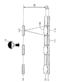
本発明に係わる画像表示装置の第一の実施例について図1を参照して説明する。尚、本実施例は表示画像が表示面の前方に結像する形態に関する。
【0046】
画像表示装置の表示面11の前方に距離S1を有してレンズアレイ12が配置される。レンズアレイ12は焦点距離がf1のレンズ121と焦点距離がf2のレンズ122が所定の規則に従って配置されている。焦点距離f1と距離S1は第一結像面13の結像位置を決定し、観察者15の方向に向かってレンズアレイ12から距離S3の位置に画像は結像される。また、焦点距離f2と距離S1は第二結像面14の結像位置を決定し、観察者15の方向に向かってレンズアレイ12から距離S2の位置に画像は結像される。
【0047】
即ち、表示面11の画素111は第一結像面13の第一結像画素131として表示面11からS1+S3の位置に、一方、表示面11の画素112は第二結像面14の第二結像画素142として表示面11からS1+S2の位置に夫々結像されることになる。観察者15はこれら第一結像画素131及び第二結像画素142を観ることで立体感を得ることになる。尚、レンズに所定の画素以外からの外乱光が入射することを防止するために、光遮蔽部材17をレンズ間に設けても良い。
【0048】
レンズアレイ12は全て同一の焦点距離を有するものを同一の平面状に配置することで、表示面11の前方に飛び出た平面的な画像を形成することも可能である。
【0049】
また、焦点距離が異なる複数のレンズを所定の規則に従って配置するようにしても良い。焦点距離の数だけ結像面が生じ、一層滑らかな立体画像が得られる。
【0050】
(第二の実施例)
本発明に係わる画像表示装置の第二の実施例について図2を参照して説明する。画像表示装置の表示面11に密着させてレンズアレイ12を配置する。表示面11の厚み、及びレンズ12の厚みから距離S1が発生する。レンズアレイ12はレンズのない部分と焦点距離がf2のレンズ122が所定の規則に従って配置されている。焦点距離f2のレンズにより第二結像面14は観察者15方向に、レンズアレイ12から距離S2の位置に結像される。即ち、表示面11の画素112は第二結像面14の第二結像画素142として表示面11からS1+S2の位置に結像されることになり、一方、レンズでカバーされない画素は表示面11に表示されたままである。従って観察者15はこれら表示面11に表示された画像及び第二結像面14に結像された画像を観ることで立体感を得ることになる。
【0051】
また、焦点距離が更に異なる複数のレンズを所定の規則に従って配置するようにしても良い。表示面11に表示された画像と焦点距離の数だけの結像面の画像により、一層滑らかな立体画像が得られる。尚、焦点距離f2の値によっては表示面11の後方に結像することになる。
【0052】
(第三の実施例)
本発明に係わる画像表示装置の第三の実施例について図3を参照して説明する。尚、本実施例は表示画像が表示面の後方に結像する形態に関する。
【0053】
画像表示装置の表示面11の前方に距離S1を有してレンズアレイ12が配置される。レンズアレイ12は焦点距離がf1のレンズ121と焦点距離がf2のレンズ122が所定の規則に従って配置されている。焦点距離f1と距離S1は第一結像面13の結像位置を決定し、観察者15の方向に向かってレンズアレイ12から距離S3の位置に画像は結像される。また、焦点距離f2と距離S1は第二結像面14の結像位置を決定し、観察者15の方向に向かってレンズアレイ12から距離S2の位置に画像は結像される。
【0054】
即ち、表示面11の画素111は第一結像面13の第一結像画素131として表示面11からS3−S1の位置に、一方、表示面11の画素112は第二結像面14の第二結像画素142として表示面11からS2−S1の位置に夫々結像されることになり、観察者15はこれら第一結像面13と第二結像面14に結像された画像を観ることで立体感を得ることになる。
【0055】
レンズアレイ12は全て同一の焦点距離を有するものを同一の平面状に配置することで、表示面11から後方に退いた平面的な画像を形成することも可能である。
【0056】
また、焦点距離が更に異なる複数のレンズを所定の規則に従って配置するようにしても良い。表示面11に表示された画像と焦点距離の数だけの結像面の画像により、一層滑らかな立体画像が得られる。更に、レンズに所定の画素以外からの外乱光が入射することを防止するために、光遮蔽部材をレンズ間に設けても良いことは第一の実施例と同様である。
【0057】
尚、上述した各実施例において、表示面11を形成する装置は、例えばブラウン管、液晶、EL、プラズマ等のディスプレイが用いられる。また、その表示面は平面であることが好ましい。
【0058】
また、レンズは球面レンズの他に非球面レンズ、フレネルレンズ、分布屈折率レンズ等を用いることが可能である。更にレンズは凸レンズ、凹レンズ、或いはフラットな形状のものであっても良い。
【0059】
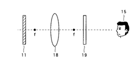
次に、図4及び図5を参照し、表示面11の前方に表示させる場合と後方に表示させる場合のレンズの焦点距離とレンズと表示面11との位置関係ついて説明する。
【0060】
まず、画像を表示面11の前方に表示させる場合は図4に示すように、表示面11をレンズ18を中心として観察者15とは反対側に、レンズ18の焦点距離f以上に離れて配置する。これによりレンズ18を介して観察者15の方向に実像として画像19が結像される。一方、画像を表示面11の後方に表示させる場合は図5に示すように、表示面11をレンズ18を中心として観察者15と反対側に、レンズ18の焦点距離f以内に配置する。これによりレンズ18を介して観察者15とは反対側に虚像として画像19が結像される。従って第一の実施例及び第二の実施例は図4に示す配置を採り、第三の実施例は図5に示す配置を採っている。
【0061】
図6は光学系を短くして表示装置をより小型化、薄型化にする手段について示す図であって、図6の上段は表示面11とレンズアレイ12は距離S11を離して配置している図である。この距離S11を短くするための手段が図6の下段に示す図であって、表示面11とレンズアレイ12との間に所定の屈折率を有する光学的に透明な部材を挿入する。従って部材の屈折率に基づいた表示面11とレンズアレイ12間の距離S12が与えられ、S12<S11となる。表示面11とレンズアレイ12間の距離を短くすることができ、表示装置の小型化、薄型化を実現する。挿入する部材として透明なガラスや、樹脂材が好適に用いられる。
【0062】
次に、上述した第一の実施例と第三の実施例に係わる変形例について図7から図9を参照して説明する。
【0063】
(第一の変形例)
まず、第一の変形例は図7に示すように、2枚のレンズアレイ12a、12bを表示面11の前方に配置する形態である。レンズアレイ12a、12bは所定の配置でレンズが形成されていて、互いにレンズが設けられていない画素をカバーする構成である。
【0064】
画像表示装置の表示面11の前方に距離S21を有してレンズアレイ12aが配置され、距離S22を有してレンズアレイ12bが配置される。レンズアレイ12aは、焦点距離がf1のレンズ121が所定の画素111に対応して形成されている。また、レンズアレイ12bは、焦点距離がf2のレンズ122が所定の画素112に対応して形成されている。焦点距離f1と焦点距離f2は同一であっても良い。
【0065】
レンズアレイ12aにより画素111の像が第一結像面13の第一結像画素131として表示面11から距離S23の位置に結像され、また、レンズアレイ12bにより画素112の像が第二結像面14の第二結像画素142として表示面11から距離S24の位置に結像される。観察者15はこれら第一結像画素131及び第二結像画素142を観ることで立体感を得ることになる。レンズアレイ12a、12bの距離S21、S22を変えることによって、第一結像面13と第二結像面14の位置を調整することが可能である。また、表示面11とレンズアレイ12a、12bの距離を焦点距離よりも短くすることで、第一結像面13と第二結像面14の両方を表示面11の後方に設定することができる。また、何れか一方のレンズアレイの位置を表示面11とレンズの焦点の間にすることで、一方は表示面11の前方に、他の一方は表示面11の後方に結像させることも可能である。
【0066】
レンズアレイ12a、12bは共に同一の焦点距離を有するレンズを備えていても良く、または、異なった焦点距離のレンズを備えていても良い。また、更に複数枚のレンズアレイで構成するようにしても良い。これによりレンズアレイの数だけ結像面が生じ、一層滑らかな立体画像が得られる。
【0067】
(第二の変形例)
次に、第二の変形例は図8に示すように、画像表示装置の表示面11の前方に距離S31を有してレンズアレイ12cが配置される。レンズアレイ12cは前後に配置された焦点距離がf1のレンズ群と焦点距離がf2のレンズ群とからなる。夫々のレンズ群のレンズは画素111、画素112に対応して形成されている。焦点距離f1と焦点距離f2は同じであっても良い。
【0068】
レンズアレイ12cのレンズ121により画素111の像が第一結像面13の第一結像画素131として表示面11から距離S32の位置に結像され、また、レンズアレイ12cのレンズ122により画素112の像が第二結像面14の第二結像画素142として表示面11から距離S33の位置に結像される。観察者15はこれら第一結像画素131及び第二結像画素142を観ることで立体感を得ることになる。レンズアレイ12cの距離S31を変えることによって、第一結像面13と第二結像面14の位置が調整される。また、表示面11とレンズアレイ12cの距離を制御することで、即ちレンズの焦点距離内にレンズアレイ12cを設定することで、レンズ第一結像面13と第二結像面14を表示面11の後方に設定することができる。更に、一方のレンズをそのレンズの焦点距離内に配置することで、いずれか一方の結像面を表示面11の前方に、他の一方を後方に配置することができる。
【0069】
(第三の変形例)
次に、第三の変形例は図9に示すように、画像表示装置の表示面11の前方に距離S41を有してレンズアレイ12dが配置される。レンズアレイ12dは全ての画素をカバーする焦点距離がf1のレンズ群と所定の画素カバーする焦点距離がf2のレンズ群とからなる。
【0070】
レンズアレイ12dのレンズ121aとレンズ121bの複合レンズにより画素111の像が第一結像面13の第一結像画素131として表示面11から距離S42の位置に結像され、また、レンズアレイ12dのレンズ122により画素112の像が第二結像面14の第二結像画素142として表示面11から距離S43の位置に結像される。観察者15はこれら第一結像画素131及び第二結像画素142を観ることで立体感を得ることになる。
【0071】
レンズアレイ12dの距離S41を変えることによって、第一結像面13と第二結像面14の位置が調整される。また、表示面11とレンズアレイ12c距離を制御することで第一結像面13と第二結像面14の両方、或いはいずれか一方を表示面11の背面に設定することができる。
【0072】
次に、画素とレンズとの関係について図10及び図11を参照して説明する。まず、図10はその一例であって、表示面11はX、Y方向に配置された画素111で構成され、レンズアレイ12は夫々の画素111に対応したレンズ121で構成される。レンズ121の夫々は対応する画素111の画像を結像する形態である。また、図11は他の例であって、に表示面11はX、Y方向に配置された画素111で構成されるが、レンズアレイ12は複数の画素111に対応したレンズ121で構成される。図11ではX、Y方向の夫々2画素の合計4画素に対応している。更に多くの画素に対応させても良い。レンズ121の夫々は対応する複数の画素111の画像を結像する形態である。
【0073】
(表示形態の第一の例)
図12に示すように表示形態の第一の例は、表示面11aはX方向とY方向の夫々の方向に画素単位で分割され、画素111と画素112の夫々には対応した画像情報が入力され表示される。レンズアレイ12もX方向とY方向の夫々の方向に画素単位で分割され、画素111と画素112とに対応してレンズ121とレンズ122が配置されている。第一結像面13は画素111がレンズ121によって結像(第一結像画素131)される面であり、第二結像面14は画素112がレンズ122によって結像(第一結像画素142)される面である。
【0074】
尚、レンズ121とレンズ122は図11に示すよう複数の画素をカバーするように構成されていても良い。このときレンズ121又はレンズ122がカバーする画素の全ては、同一の結像面に結像させる画像情報で表示されている必要のあることは当然である。
【0075】
また、図13に示すように表示形態の第二の例は、表示面11bはX方向に分割され、画素111と画素112の夫々に対応した画像が表示される。レンズアレイ12も画素111と画素112の夫々に対応して縦一列が同じ焦点距離を有するレンズ121とレンズ122が配置されている。第一結像面13は画素111がレンズ121によって縦方向の一列に結像(第一結像画素131)される面であり、第二結像面14は画素112がレンズ122によって縦方向の一列に結像(第一結像画素142)される面である。
【0076】
尚、レンズ121とレンズ122に対応する画素は横方向の複数の画素列で構成されていても良い。このときレンズ121又はレンズ122がカバーする画素の全ては、同一の結像面に結像させる画像情報で表示されている必要のあることは当然である。
【0077】
また、図14に示すように表示形態の第三の例は、表示面11cはY方向に分割され、画素111と画素112の夫々に対応した画像が表示される。レンズアレイ12も画素111と画素112の夫に対応して横一列が同じ焦点距離を有するレンズ121とレンズ122が配置されている。第一結像面13は画素111がレンズ121によって横方向の一列に結像(第一結像画素131)される面であり、第二結像面14は画素112がレンズ122によって横方向の一列に結像(第一結像画素142)される面である。
【0078】
尚、レンズ121とレンズ122に対応する画素は縦方向の複数の画素列で構成されていても良い。このときレンズ121又はレンズ122がカバーする画素の全ては、同一の結像面に結像させる画像情報で表示されている必要のあることは当然である。
【0079】
尚、図15(a)に示したように、図13に示す表示形態の例において、縦方向(Y方向)に延びるストライプ状の表示面11bに沿って配置されたロッドレンズやレンチキュラレンズ(即ち、かまぼこ状のレンズ)等の柱状レンズアレイ12Lが使用可能である。図13に示した第一結像面13及び第二結像面14の夫々に結像させる柱状レンズアレイ12Lを構成する各ロッドレンズ或いは各レンチキュラレンズの焦点距離は夫々の結像面に対応して同一の焦点距離に設定される。即ち図13に示すように一列おきに2つの結像面に対応した焦点距離が交互に備わる。このようなレンズは作成が容易であり、安価なシステムの構成に効果が大きい。
【0080】
同様に、図15(b)に示したように、図14に示す表示形態の例において、横方向(X方向)に延びるストライプ状の表示面11cに沿って配置されたロッドレンズやレンチキュラレンズ等の柱状レンズアレイ12Lが使用可能である。図14に示した第一結像面13及び第二結像面14の夫々に結像させる柱状レンズアレイ12Lを構成する各ロッドレンズ或いは各レンチキュラレンズの焦点距離は夫々の結像面に対応して同一の焦点距離に設定される。即ち図14に示すように一行おきに2つの結像面に対応した焦点距離が交互に備わる。
【0081】
(画像表示装置の第一実施例)
本発明に係わる画像表示装置の第一実施例について図16を参照して説明する。本実施例の画像表示装置1は、表示する画像を発生する第一画像発生部21及び第二画像発生部22、第一画像発生部21と第二画像発生部22の画像信号を選択する信号切り替え部23、選択された信号に基づき表示装置を駆動する駆動部24、立体画像を表示する表示部25、装置全体の動作をコントロールする制御部26を備えて構成される。
【0082】
第一画像発生部21及び第二画像発生部22は、夫々第一結像面13及び第二結像面14に結像させる画像を供給するための信号源であって、放送されてくる画像、ビデオの再生画像、コンピュータによるグラフィック画像等、種々のものが想定される。
【0083】
信号切り替え部23は、第一画像発生部21及び第二画像発生部22からの信号をスイッチし、表示すべき画像を選択する。表示部25の構成が図12に示す形態であれば、一画素ごとに切り替えが行われる。また、図13に示す形態であれば、横の一ラインごとに、或いは図14に示す形態であれば縦一列に同じ画像発生部の信号が表示されるように切り替えが行われる。更に、複数の画素にレンズが対応していればそれらの画素は同じ画像発生部の信号が表示されるように切り替えが行われる。
【0084】
駆動部24は、信号切り替え部23で選択された信号を表示装置に入力し、表示部25に表示させる。
【0085】
表示部25は、選択された画像を表示し、観察者15に立体の画像を視覚させる。表示装置としては、例えばブラウン管、液晶、EL、プラズマ等の表示装置があり、表示部25はフラットであることが好ましい。
【0086】
制御部26は、画像表示装置1の動作のコントロールを行う。例えばCPUを備え、第一画像発生部21及び第二画像発生部22の同期タイミングを揃え、また、同期タイミングに基づいて信号切り替え部23の切り替えを指示する。
【0087】
(画像表示装置の第二実施例)
本発明に係わる画像表示装置の第二実施例について図17を参照して説明する。本実施例の画像表示装置2は、表示する画像を発生する第一画像発生部31及び第二画像発生部32、第一画像発生部21の画像を記憶する画像メモリ33、第二画像発生部32の画像を記憶する画像メモリ34、画像メモリ33と画像メモリ34に記憶されている画像情報を合成する画像合成部35、画像合成部35で合成された画像情報を記録媒体37に記録する記録部38、記録媒体37を再生する再生部39、立体画像を表示する表示部40、装置全体の動作をコントロールする制御部41を備えて構成される。
【0088】
第一画像発生部21及び第二画像発生部22は、夫々第一結像面13及び第二結像面14に結像させる画像を供給するための信号源であって、放送されてくる画像、ビデオの再生画像、コンピュータによるグラフィック画像等、種々のものが想定される。
【0089】
画像メモリ33と画像メモリ34は、夫々第一画像発生部21及び第二画像発生部22からの信号を一時、記憶する。記憶する画像は少なくともフィールド画像、好ましくはフレーム画像とする。
【0090】
画像合成部35は、画像メモリ33と画像メモリ34に記憶されている画像情報から、表示すべき画像を形成する。例えば表示する形態が図12に示す形態であれば、一画素ごとに画像が形成され、図13に示す形態であれば、横の一ラインごとに同一の画像が配置され、或いは図14に示す形態であれば縦の一列ごとに同一の画像が配置される。
【0091】
記録部38は、画像合成部35で形成された画像情報を記録媒体37に記録する。記録媒体37としては磁気記録媒体、光記録媒体、半導体記録媒体等が用いられる。
【0092】
再生部39は、記録媒体37に記録された画像情報を再生して表示装置に入力し、表示部40に表示させる。このように記録媒体37を介在させることで三次元画像ソフトを蓄積させ、また、広範に頒布することが可能となる。
【0093】
表示部40は、記録媒体37から再生された画像を表示し、観察者15に三次元の画像を視覚させる。表示装置としては、例えばブラウン管、液晶、EL、プラズマ等の表示装置があり、表示部25はフラットであることが好ましい。
【0094】
制御部41は、画像表示装置2動作のコントロールを行う。例えばCPUを備え、第一画像発生部21及び第二画像発生部22からの画像サンプルタイミングの指示や、記録部38、再生部39の動作制御を行う。
【0095】
尚、画像合成部35で形成された画像情報を直接、駆動部42に入力して表示部40に表示させるようにしても良い。
【0096】
以上説明した画像表示装置1及び画像表示装置2によれば、2種類の画像信号源から、夫々の信号を異なる結像面に結像させることで、観察者に対して三次元の画像を視覚させることが可能であり、また、2つの信号を同一の結像面に結像させることで、表示面とは異なる面に二次元の画像を視覚させることが可能となる。
【0097】
尚、上述した画像表示装置1及び画像表示装置2は2つの結像面を備えた装置であるが、更に光学系、信号系を3つ以上備えた3つ以上の結像面を有する画像表示を形成することも可能である。
【0098】
本発明は、上述した実施形態に限られるものではなく、請求の範囲及び明細書全体から読み取れる発明の要旨或いは思想に反しない範囲で適宜変更可能であり、そのような変更を伴う画像表示装置及び画像表示方法もまた本発明の技術思想に含まれるものである。
【図面の簡単な説明】
【図1】本発明に係わる画像表示装置の第一の実施例について示す図である。
【図2】本発明に係わる画像表示装置の第二の実施例について示す図である。
【図3】本発明に係わる画像表示装置の第三の実施例について示す図である。
【図4】画像の結像位置について説明するための図である。
【図5】画像の結像位置について説明するための図である。
【図6】表示装置の小型化、薄型化についての手段を示す図である。
【図7】本発明に係わる画像表示装置の第一の変形例について示す図である。
【図8】本発明に係わる画像表示装置の第二の変形例について示す図である。
【図9】本発明に係わる画像表示装置の第三の変形例について示す図である。
【図10】表示する画像素子とレンズの関係を示す図である。
【図11】表示する画像素子とレンズの関係を示す図である。
【図12】画像の表示形態の第一の例について示す図である。
【図13】画像の表示形態の第二の例について示す図である。
【図14】画像の表示形態の第三の例について示す図である。
【図15】図13又は図14に示した表示形態の例において、ストライプ状の表示面に沿って配置された柱状レンズアレイに係る変形例を示す図である。
【図16】本発明に係わる画像表示装置の具体的構成の一例を示すブロック図である。
【図17】本発明に係わる画像表示装置の具体的構成の他の例を示すブロック図である。
【符号の説明】
1、2・・・画像表示装置
11・・・表示面
111、112・・・画素
12・・・レンズアレイ
121、122・・・レンズ
13・・・第一結像面
131・・・第一結像画素
14・・・第二結像面
142・・・第二結像画素
15・・・観察者
16・・・光透過部材
17・・・光遮蔽部材
21、31・・・第一画像発生部
22、32・・・第二画像発生部
23・・・信号切り替え部
24・・・駆動部
25、40・・・表示部
26、41・・・制御部
33、34・・・画像メモリ
35・・・画像合成部
37・・・記録部
38・・・記録媒体
39・・・再生部[0001]
TECHNICAL FIELD OF THE INVENTION
The present invention belongs to the technical field of an image display device and an image display method capable of displaying images including three-dimensional image display.
[0002]
[Prior art]
2. Description of the Related Art Conventionally, there has been a display device using a device such as a cathode ray tube, an EL, a liquid crystal, and a plasma. They have a form in which an image displayed on a display surface of a display device is directly viewed as a two-dimensional image. On the other hand, there is a three-dimensional image display device that displays a three-dimensional image in which an image can be viewed as a three-dimensional image using these display devices, and various forms have been proposed and implemented. The three-dimensional image is used in, for example, the fields of entertainment, design, medical treatment, and the like, and more effective three-dimensional image display means is desired.
[0003]
As an example of the three-dimensional image display device, for example, a liquid crystal shutter glasses system is well known. In this method, a three-dimensional object is photographed from different directions by a camera, and image data including the obtained parallax information is synthesized into one image signal, and input to a two-dimensional display device for display. The observer wears liquid crystal shutter glasses, for example, in the odd field, the liquid crystal shutter for the right eye is in the light transmitting state and the liquid crystal shutter for the left eye is in the light blocking state. Liquid crystal shutter is in a light blocking state. At this time, a right-eye image is displayed in an odd field and a left-eye image is displayed in an even field in synchronization with each other to obtain a stereoscopic image by viewing images including parallax for the right and left eyes with each eye. It is.
[0004]
There is also a three-dimensional display device in which a plurality of display means are provided in the front-rear direction with respect to the line of sight of an observer, and a three-dimensional image is viewed from the luminance of an object displayed on each of the display means.
[0005]
[Problems to be solved by the invention]
However, these methods require a device to be worn by an observer and signal processing for three-dimensional display of an image to be displayed, or have a plurality of display devices, or the display device itself has a complicated configuration. there were. In addition, when viewing a three-dimensional image by a method using parallax, it is said that eye fatigue is large.
[0006]
Accordingly, the present invention has been made in view of the above problems, and forms an image displayed on a screen of a two-dimensional display device at a predetermined position, so that the observer not only displays a two-dimensional image but also displays a three-dimensional image. It is an object of the present invention to provide an effective image display device and an effective image display method with a relatively simple configuration capable of viewing an image.
[0007]
[Means for Solving the Problems]
In order to solve the above problem, the invention according to
[0008]
The invention according to
[0009]
According to a twentieth aspect of the present invention, an image forming means comprising a plurality of lenses is provided in front of the display surface of the two-dimensional image display means in parallel with the display surface, and the two-dimensional image display means is provided with an image signal. An image display method which inputs an image signal generated by a generation unit, displays an image, and forms the displayed image on a position different from the display surface by the image imaging unit. I do.
[0010]
Further, the invention according to
[0011]
BEST MODE FOR CARRYING OUT THE INVENTION
An embodiment of the present invention will be described below.
[0012]
An image display device according to an embodiment of the present invention includes: a two-dimensional image display unit; and an image forming unit including a plurality of lenses provided in front of a display surface of the two-dimensional image display unit and in parallel with the display surface. And an image signal generating means for generating an image signal input to the two-dimensional image display means.
[0013]
According to the image display device of the present invention, the image displayed on the display surface is formed at a position different from the display surface by the image forming device placed in front of the display surface of the two-dimensional image display device. The image forming position is determined based on the relationship between the focal length of the lens of the image forming means and the distance between the lens and the display surface, and the image is formed forward or rearward from the display surface. The observer can see the displayed image forward or backward from the display surface by looking at the formed image. The image display device preferably has a flat display surface. Further, depending on the arrangement of the image forming means and the two-dimensional image display means, the image can be formed larger or smaller than the size of the display surface.
[0014]
An image display device according to an embodiment of the present invention includes a two-dimensional image display unit, and a plurality of lenses provided in front of a display surface of the two-dimensional image display unit and in parallel with the display surface. Lens generates an image signal displayed on the two-dimensional image display means corresponding to each of the focal lengths of the image forming means having any one of a plurality of focal lengths and the lens. Image signal generating means.
[0015]
According to the image display device of the present invention, the image displayed on the display surface is different from the display surface by the image forming device placed in front of the display surface of the two-dimensional image display device, and the focal length of each lens. Is formed at a position based on the relationship between the distance between the lens and the display surface, and the observer can view the image as a three-dimensional image forward or backward from the display surface. The image signal generation means generates and displays an image signal corresponding to each lens. The image display device preferably has a flat display surface. Further, depending on the arrangement of the image forming means and the two-dimensional image display means, the image can be formed larger or smaller than the size of the display surface. By arranging more lenses having different focal lengths, more image planes can be set, and a smoother three-dimensional image can be viewed.
[0016]
As one mode of the image display device according to the embodiment of the present invention, the image forming means is configured by overlapping a plurality of lens arrays.
[0017]
According to this aspect, a lens array having a different focal length or a lens array having lenses only for predetermined pixels is used. Further, in a lens array in which a portion where a lens is provided and a portion where a lens is not provided are arranged at equal intervals at the same size, two lens arrays are overlapped with a portion having a lens and a portion having no lens, and are respectively disposed at a predetermined distance from a display surface. , Two imaging planes can be obtained. Since the same lens array is used, an optical system can be configured at low cost. Further, the focal lengths of the respective lenses of the two lens arrays to be combined may be different.
[0018]
As another aspect of the image display device according to the embodiment of the present invention, the image forming unit is configured such that an image of the two-dimensional image display unit by the image forming unit is displayed on a display surface of the two-dimensional image display unit. It is configured to be set at a position where an image is formed forward.
[0019]
The image forming means is set at a position where an image of the two-dimensional image display means by the image forming means is formed behind a display surface of the two-dimensional image display means.
[0020]
According to this aspect, based on the relationship between the focal length of the lens and the distance between the lens and the display surface, the imaging position of the display image of the two-dimensional image display means is set to the front or the rear of the display surface. Can be. The observer can see the three-dimensional image in front of or behind the display surface by viewing the image.
[0021]
As another mode of the image display device according to the embodiment of the present invention, the lens may be any of an aspherical lens, a Fresnel lens, and a distributed index lens.
[0022]
According to this aspect, the form of the lens can be selected based on the use form, conditions, and the like of the apparatus. Further, the lens may be a convex lens, a concave lens, or a flat lens.
[0023]
As another aspect of the image display device according to the embodiment of the present invention, a member having a predetermined refractive index is inserted between the lens and the two-dimensional image display means.
[0024]
According to this aspect, by inserting a transparent member having a high refractive index between the lens and the display surface of the two-dimensional image display means, the optical path can be shortened, and the device can be reduced in size and thickness.
[0025]
In order to reduce the size or thickness, it is preferable that the distance between the lens and the two-dimensional image display means is shortened by the lens itself. However, when this is difficult, the effect of using this embodiment is advantageous. growing.
[0026]
As another mode of the image display device according to the embodiment of the present invention, a separating unit for optically separating the lenses is provided between the lens and the two-dimensional image displaying unit.
[0027]
According to this aspect, since light from adjacent pixels and surroundings can be blocked, the quality of an image to be formed is improved. In addition, it is preferable that each lens itself is a lens which is not affected by light from an adjacent pixel or the surroundings. However, when this is difficult, the effect is large by using this embodiment.
[0028]
As another aspect of the image display device according to the embodiment of the present invention, the two-dimensional image display means can use any of a cathode ray tube display means, a liquid crystal display means, an EL display means, and a plasma display means.
[0029]
According to this aspect, it is preferable that the display surface is particularly flat as the two-dimensional image display means, and the two-dimensional image display means such as a cathode ray tube display means, a liquid crystal display means, an EL display means, and a plasma display means is used for image display. The selection can be made based on the type of use of the device, conditions, and the like.
[0030]
As another aspect of the image display device according to the embodiment of the present invention, the lens is provided corresponding to each of the pixels of the two-dimensional image display means.
[0031]
According to this aspect, since the lens is provided corresponding to each of the pixels of the two-dimensional image display means, the brightness and the image quality of all the pixels are at the same level, and a high-quality image can be obtained. .
[0032]
As another aspect of the image display device according to the embodiment of the present invention, the lens is provided corresponding to a predetermined pixel block of the two-dimensional image display means.
[0033]
According to this aspect, since one lens corresponds to a plurality of pixels of the two-dimensional image display means, the configuration of the lens array is simplified.
[0034]
As another aspect of the image display device according to the embodiment of the present invention, the lens is provided corresponding to a horizontal line of the two-dimensional image display means.
[0035]
According to this aspect, since a lens having the same focal length is associated with each horizontal line of the two-dimensional image display means, pixels on the same horizontal line are imaged on the same image plane. Therefore, since the pixels on the same horizontal line display the image on the same image plane, it is easy to create an image to be input to the two-dimensional image display means.
[0036]
As another aspect of the image display device according to the embodiment of the present invention, the lens is provided corresponding to a vertical line of the two-dimensional image display means.
[0037]
According to this aspect, since a lens having the same focal length is associated with each vertical line of the two-dimensional image display means, pixels on the same vertical line are imaged on the same image plane. Therefore, since the pixels on the same vertical line display an image on the same image plane, it is easy to create an image to be input to the two-dimensional image display means.
[0038]
As another aspect of the image display device according to the embodiment of the present invention, the image signal generating means includes luminance information, color information, size information, and focus information added to an image displayed on the display surface. And at least one piece of information.
[0039]
According to this aspect, a more effective stereoscopic image can be obtained depending on the position where the image is formed. That is, according to the display content, the brightness, the color, the size, the sense of focus, and the like are changed, and a synergistic effect that makes the sense of depth and the sense of three-dimensional feel more is obtained by combining these elements. For example, with respect to luminance, the front is bright and the back is dark and shaded, and the size is large in the front and small in the back. With respect to color, yellow appears to the front, blue appears to the back, and a sense of focus, that is, the front is felt when the subject is in focus, and the back is felt when the subject is out of focus. One or more pieces of information such as brightness, color, size, and sense of focus are added to the image displayed on the display surface in accordance with the position where the image is formed, and the image is displayed according to the information when displayed. Convert and output. Alternatively, images converted on the basis of the information may be stored and sequentially output. By introducing the above-described method, a more effective stereoscopic image can be obtained.
[0040]
An image display method according to an embodiment of the present invention is provided with an image forming unit comprising a plurality of lenses in parallel with the display surface in front of the display surface of the two-dimensional image display unit, and the two-dimensional image display unit This is a method in which an image signal generated by the image signal generating means is input to display an image, and the displayed image is formed by the image forming means at a position different from the display surface.
[0041]
According to the image display method of the present invention, the image displayed on the display surface is at a position different from the display surface, that is, at a position determined based on the relationship between the focal length of the lens and the distance between the lens and the display surface. The image is formed, and the observer can view the displayed image forward or backward from the display surface.
[0042]
An image display method according to an embodiment of the present invention comprises a plurality of lenses in front of a display surface of a two-dimensional image display means, parallel to the display surface, and each lens has a plurality of focal lengths. An image forming unit having any one of the focal lengths is provided, and an image signal generated corresponding to each focal length of the lens by the image signal generating unit is input to the two-dimensional image display unit to display an image. Then, the displayed image is formed by the image forming means at a position different from the display surface.
[0043]
According to the image display method of the present invention, an image displayed on the display surface is determined based on a position different from the display surface, that is, a focal length of a plurality of lenses and a relationship between the distance between the lenses and the display surface. The image is formed at a plurality of positions, and the observer can view the formed image to see it as a three-dimensional image.
[0044]
The operation and other advantages of the present invention will become more apparent from the embodiments explained below.
[0045]
【Example】
(First embodiment)
A first embodiment of the image display device according to the present invention will be described with reference to FIG. This embodiment relates to a mode in which a display image is formed in front of a display surface.
[0046]
A
[0047]
That is, the
[0048]
By arranging all the
[0049]
Further, a plurality of lenses having different focal lengths may be arranged according to a predetermined rule. Imaging planes are generated by the number of focal lengths, and a smoother stereoscopic image can be obtained.
[0050]
(Second embodiment)
A second embodiment of the image display device according to the present invention will be described with reference to FIG. The
[0051]
Further, a plurality of lenses having further different focal lengths may be arranged according to a predetermined rule. With the images displayed on the
[0052]
(Third embodiment)
A third embodiment of the image display device according to the present invention will be described with reference to FIG. This embodiment relates to a mode in which a display image is formed behind a display surface.
[0053]
A
[0054]
That is, the
[0055]
By arranging all the
[0056]
Further, a plurality of lenses having further different focal lengths may be arranged according to a predetermined rule. With the images displayed on the
[0057]
In each of the above-described embodiments, as a device for forming the
[0058]
As the lens, an aspherical lens, a Fresnel lens, a distributed index lens, or the like can be used in addition to the spherical lens. Further, the lens may be a convex lens, a concave lens, or a flat lens.
[0059]
Next, with reference to FIGS. 4 and 5, a description will be given of the focal length of the lens and the positional relationship between the lens and the
[0060]
First, when displaying an image in front of the
[0061]
FIG. 6 is a diagram showing a means for shortening the optical system to make the display device smaller and thinner. In the upper part of FIG. 6, the
[0062]
Next, modifications of the first and third embodiments will be described with reference to FIGS.
[0063]
(First modification)
First, as shown in FIG. 7, a first modified example is a mode in which two
[0064]
The lens array 12a is arranged at a distance S21 in front of the
[0065]
The lens array 12a forms an image of the
[0066]
The
[0067]
(Second modification)
Next, in the second modification, as shown in FIG. 8, a
[0068]
The image of the
[0069]
(Third modification)
Next, in the third modification, as shown in FIG. 9, a
[0070]
The image of the
[0071]
By changing the distance S41 of the
[0072]
Next, the relationship between the pixel and the lens will be described with reference to FIGS. First, FIG. 10 is an example, in which the
[0073]
(First example of display form)
As shown in FIG. 12, in the first example of the display mode, the
[0074]
Note that the
[0075]
As shown in FIG. 13, in the second example of the display mode, the
[0076]
The pixels corresponding to the
[0077]
As shown in FIG. 14, in a third example of the display mode, the
[0078]
The pixels corresponding to the
[0079]
As shown in FIG. 15A, in the example of the display form shown in FIG. 13, a rod lens or a lenticular lens (that is, a rod lens or a lenticular lens arranged along a stripe-shaped
[0080]
Similarly, as shown in FIG. 15B, in the example of the display form shown in FIG. 14, a rod lens, a lenticular lens, and the like arranged along a stripe-shaped
[0081]
(First Embodiment of Image Display Device)
A first embodiment of the image display device according to the present invention will be described with reference to FIG. The
[0082]
The first
[0083]
The
[0084]
The
[0085]
The
[0086]
The
[0087]
(Second embodiment of image display device)
A second embodiment of the image display device according to the present invention will be described with reference to FIG. The
[0088]
The first
[0089]
The
[0090]
The
[0091]
The
[0092]
The
[0093]
The
[0094]
The
[0095]
The image information formed by the
[0096]
According to the
[0097]
Note that the
[0098]
The present invention is not limited to the above-described embodiment, but can be appropriately changed within a scope not contrary to the gist or idea of the invention which can be read from the claims and the entire specification, and an image display device with such a change and The image display method is also included in the technical idea of the present invention.
[Brief description of the drawings]
FIG. 1 is a diagram showing a first embodiment of an image display device according to the present invention.
FIG. 2 is a diagram showing a second embodiment of the image display device according to the present invention.
FIG. 3 is a diagram showing a third embodiment of the image display device according to the present invention.
FIG. 4 is a diagram for explaining an image forming position of an image.
FIG. 5 is a diagram for explaining an image forming position of an image.
FIG. 6 is a diagram showing means for reducing the size and thickness of the display device.
FIG. 7 is a diagram showing a first modified example of the image display device according to the present invention.
FIG. 8 is a diagram showing a second modified example of the image display device according to the present invention.
FIG. 9 is a diagram showing a third modification of the image display device according to the present invention.
FIG. 10 is a diagram illustrating a relationship between an image element to be displayed and a lens.
FIG. 11 is a diagram showing a relationship between an image element to be displayed and a lens.
FIG. 12 is a diagram showing a first example of a display mode of an image.
FIG. 13 is a diagram illustrating a second example of a display mode of an image.
FIG. 14 is a diagram showing a third example of a display mode of an image.
FIG. 15 is a view showing a modification of the columnar lens array arranged along the stripe-shaped display surface in the example of the display mode shown in FIG. 13 or FIG.
FIG. 16 is a block diagram illustrating an example of a specific configuration of an image display device according to the present invention.
FIG. 17 is a block diagram showing another example of the specific configuration of the image display device according to the present invention.
[Explanation of symbols]
1, 2,... Image display device
11 ・ ・ ・ Display surface
111, 112 ... pixels
12 ... Lens array
121, 122 ... lens
13: First imaging plane
131: first image pixel
14 ... second imaging surface
142 ... second imaging pixel
15 ... observer
16 ... light transmitting member
17 ... Light shielding member
21, 31... First image generation unit
22, 32... Second image generating unit
23 ・ ・ ・ Signal switching unit
24 ・ ・ ・ Drive unit
25, 40 ... display unit
26, 41 ... control unit
33, 34 ... Image memory
35 ... Image synthesis unit
37 ・ ・ ・ Recording unit
38 ・ ・ ・ Recording medium
39 ・ ・ ・ Playback unit
Claims (21)
前記二次元画像表示手段の表示面前方に、当該表示面と平行に設けられた複数のレンズからなる画像結像手段と、
前記二次元画像表示手段に入力される画像信号を生成する画像信号生成手段と
を備えることを特徴とする画像表示装置。Two-dimensional image display means,
Image imaging means comprising a plurality of lenses provided in parallel with the display surface in front of the display surface of the two-dimensional image display means,
An image display device comprising: an image signal generation unit that generates an image signal input to the two-dimensional image display unit.
前記二次元画像表示手段の表示面前方に、当該表示面と平行に設けられた複数のレンズからなり、且つ、夫々のレンズは複数の焦点距離のうちの何れか1つの焦点距離を有する画像結像手段と、
前記レンズの夫々の焦点距離に対応し、前記二次元画像表示手段に表示される画像信号を生成する画像信号生成手段と
を備えることを特徴とする画像表示装置。Two-dimensional image display means,
In front of the display surface of the two-dimensional image display means, there are a plurality of lenses provided in parallel with the display surface, and each lens has an image formation having any one of a plurality of focal lengths. Image means,
An image display device comprising: an image signal generating unit that generates an image signal displayed on the two-dimensional image display unit, corresponding to each focal length of the lens.
を特徴とする請求項1又は2に記載の画像表示装置。The image display device according to claim 1, wherein the image forming unit is configured by stacking a plurality of lens arrays.
を特徴とする請求項1又は2に記載の画像表示装置。The image forming means is set at a position where an image of the two-dimensional image displaying means by the image forming means is formed in front of a display surface of the two-dimensional image displaying means. Item 3. The image display device according to item 1 or 2.
を特徴とする請求項1又は2に記載の画像表示装置。The image forming means is set at a position where an image of the two-dimensional image display means by the image forming means is formed behind a display surface of the two-dimensional image display means. Item 3. The image display device according to item 1 or 2.
を特徴とする請求項1又は2に記載の画像表示装置。The image display device according to claim 1, wherein the lens is an aspherical lens.
を特徴とする請求項1又は2に記載の画像表示装置。The image display device according to claim 1, wherein the lens is a Fresnel lens.
を特徴とする請求項1又は2に記載の画像表示装置。The image display device according to claim 1, wherein the lens is a distributed index lens.
を特徴とする請求項1又は2に記載の画像表示装置。3. The image display device according to claim 1, wherein a member having a predetermined refractive index is inserted between the lens and the two-dimensional image display unit.
を特徴とする請求項1又は2に記載の画像表示装置。The image display apparatus according to claim 1, further comprising: a separation unit that optically separates the lenses between the lens and the two-dimensional image display unit.
を特徴とする請求項1又は2に記載の画像表示装置。The image display device according to claim 1, wherein the two-dimensional image display unit is a cathode ray tube display unit.
を特徴とする請求項1又は2に記載の画像表示装置。The image display device according to claim 1, wherein the two-dimensional image display unit is a liquid crystal display unit.
Luminescence)表示手段であること
を特徴とする請求項1又は2に記載の画像表示装置。The two-dimensional image display means is an EL (Electronic).
3. The image display device according to claim 1, wherein the image display device is a Luminescence display unit.
を特徴とする請求項1又は2に記載の画像表示装置。The image display device according to claim 1, wherein the two-dimensional image display unit is a plasma display unit.
を特徴とする請求項1又は2に記載の画像表示装置。3. The image display device according to claim 1, wherein the lens is provided corresponding to each of the pixels of the two-dimensional image display unit.
を特徴とする請求項1又は2に記載の画像表示装置。3. The image display device according to claim 1, wherein the lens is provided corresponding to a predetermined pixel block of the two-dimensional image display unit.
を特徴とする請求項2に記載の画像表示装置。The image display device according to claim 2, wherein the lens is provided corresponding to a horizontal line of the two-dimensional image display means.
を特徴とする請求項2に記載の画像表示装置。The image display device according to claim 2, wherein the lens is provided corresponding to a vertical line of the two-dimensional image display means.
を特徴とする請求項1又は2に記載の画像表示装置。2. The image signal generating unit according to claim 1, further comprising at least one of luminance information, color information, size information, and focus information added to the image displayed on the display surface. Or the image display device according to 2.
を特徴とする画像表示方法。In front of the display surface of the two-dimensional image display means, an image forming means comprising a plurality of lenses is provided in parallel with the display surface, and an image signal generated by an image signal generation means is input to the two-dimensional image display means. An image display method, wherein the displayed image is formed at a position different from the display surface by the image forming means.
を特徴とする画像表示方法。In front of the display surface of the two-dimensional image display means, a plurality of lenses are provided in parallel with the display surface, and each lens includes an image forming means having any one of a plurality of focal lengths. Image signals generated by the image signal generation means corresponding to the respective focal lengths of the lenses are input to the two-dimensional image display means, and an image is displayed. An image display method, wherein an image is formed at a position different from the display surface by means.
Priority Applications (4)
| Application Number | Priority Date | Filing Date | Title |
|---|---|---|---|
| JP2002307938A JP2004144873A (en) | 2002-10-23 | 2002-10-23 | Picture display device and picture display method |
| AU2003280573A AU2003280573A1 (en) | 2002-10-23 | 2003-10-23 | Image display and method for displaying image |
| US10/532,057 US20060050016A1 (en) | 2002-10-23 | 2003-10-23 | Image display and method for displaying image |
| PCT/JP2003/013570 WO2004038486A1 (en) | 2002-10-23 | 2003-10-23 | Image display and method for displaying image |
Applications Claiming Priority (1)
| Application Number | Priority Date | Filing Date | Title |
|---|---|---|---|
| JP2002307938A JP2004144873A (en) | 2002-10-23 | 2002-10-23 | Picture display device and picture display method |
Publications (2)
| Publication Number | Publication Date |
|---|---|
| JP2004144873A true JP2004144873A (en) | 2004-05-20 |
| JP2004144873A5 JP2004144873A5 (en) | 2005-11-10 |
Family
ID=32454211
Family Applications (1)
| Application Number | Title | Priority Date | Filing Date |
|---|---|---|---|
| JP2002307938A Pending JP2004144873A (en) | 2002-10-23 | 2002-10-23 | Picture display device and picture display method |
Country Status (1)
| Country | Link |
|---|---|
| JP (1) | JP2004144873A (en) |
Cited By (8)
| Publication number | Priority date | Publication date | Assignee | Title |
|---|---|---|---|---|
| JP2005352392A (en) * | 2004-06-14 | 2005-12-22 | Ricoh Co Ltd | Microlens array, spatial optical modulation device, and projector apparatus |
| JP2010231010A (en) * | 2009-03-27 | 2010-10-14 | Seiko Epson Corp | Electrooptical device |
| JP2011186431A (en) * | 2010-03-04 | 2011-09-22 | Samsung Electronics Co Ltd | Display device |
| KR101363244B1 (en) | 2011-06-10 | 2014-02-12 | 후지쯔 가부시끼가이샤 | Stereoscopic image display device |
| JP2015087745A (en) * | 2013-09-27 | 2015-05-07 | パナソニックIpマネジメント株式会社 | Image display device |
| KR20160010108A (en) * | 2014-07-18 | 2016-01-27 | 삼성전자주식회사 | Method for a focus control and electronic device thereof |
| WO2016139769A1 (en) * | 2015-03-04 | 2016-09-09 | パイオニア株式会社 | Lens array and image projection device |
| JP2020013151A (en) * | 2019-09-20 | 2020-01-23 | 日本精機株式会社 | Lens array and head-up display |
-
2002
- 2002-10-23 JP JP2002307938A patent/JP2004144873A/en active Pending
Cited By (15)
| Publication number | Priority date | Publication date | Assignee | Title |
|---|---|---|---|---|
| JP2005352392A (en) * | 2004-06-14 | 2005-12-22 | Ricoh Co Ltd | Microlens array, spatial optical modulation device, and projector apparatus |
| JP2010231010A (en) * | 2009-03-27 | 2010-10-14 | Seiko Epson Corp | Electrooptical device |
| JP2011186431A (en) * | 2010-03-04 | 2011-09-22 | Samsung Electronics Co Ltd | Display device |
| KR101363244B1 (en) | 2011-06-10 | 2014-02-12 | 후지쯔 가부시끼가이샤 | Stereoscopic image display device |
| US8847853B2 (en) | 2011-06-10 | 2014-09-30 | Fujitsu Limited | Stereoscopic image display device |
| US9787972B2 (en) | 2013-09-27 | 2017-10-10 | Panasonic Intellectual Property Management Co., Ltd. | Image display device |
| JP2015087745A (en) * | 2013-09-27 | 2015-05-07 | パナソニックIpマネジメント株式会社 | Image display device |
| KR20160010108A (en) * | 2014-07-18 | 2016-01-27 | 삼성전자주식회사 | Method for a focus control and electronic device thereof |
| KR102266468B1 (en) * | 2014-07-18 | 2021-06-17 | 삼성전자주식회사 | Method for a focus control and electronic device thereof |
| WO2016139769A1 (en) * | 2015-03-04 | 2016-09-09 | パイオニア株式会社 | Lens array and image projection device |
| JPWO2016139769A1 (en) * | 2015-03-04 | 2017-12-14 | パイオニア株式会社 | Lens array and image projection apparatus |
| US10761323B2 (en) | 2015-03-04 | 2020-09-01 | Nippon Seiki Co., Ltd. | Lens array and image projection device |
| US11256089B2 (en) | 2015-03-04 | 2022-02-22 | Nippon Seiki Co., Ltd. | Lens array and image projection device |
| US11428932B2 (en) | 2015-03-04 | 2022-08-30 | Nippon Seiki Co., Ltd. | Lens array and image projection device |
| JP2020013151A (en) * | 2019-09-20 | 2020-01-23 | 日本精機株式会社 | Lens array and head-up display |
Similar Documents
| Publication | Publication Date | Title |
|---|---|---|
| Pastoor et al. | 3-D displays: A review of current technologies | |
| US8633967B2 (en) | Method and device for the creation of pseudo-holographic images | |
| US8427532B2 (en) | Apparatus and method of displaying the three-dimensional image | |
| US8384769B1 (en) | 3D image display method and system thereof | |
| JP4740135B2 (en) | System and method for drawing 3D image on screen of 3D image display | |
| JP4404146B2 (en) | Projection type 3D image reproduction device | |
| US7492513B2 (en) | Autostereoscopic display and method | |
| CN110809884B (en) | Visual display utilizing temporal multiplexing for stereoscopic views | |
| WO2004038486A1 (en) | Image display and method for displaying image | |
| JPWO2006061959A1 (en) | Stereoscopic two-dimensional image display apparatus and stereoscopic two-dimensional image display method | |
| JP3368204B2 (en) | Image recording device and image reproducing device | |
| JP2001235708A (en) | Stereoscopic image reproducing device with background | |
| JP2004144874A (en) | Picture display device and picture display method | |
| US20030137730A1 (en) | Autostereoscopic display | |
| Schwerdtner et al. | Dresden 3D display (D4D) | |
| KR102070800B1 (en) | Stereoscopic display apparatus, and display method thereof | |
| KR100351805B1 (en) | 3d integral image display system | |
| US20080158671A1 (en) | Three-Dimensional Image Display Apparatus Using Flat Panel Display | |
| JP2004144873A (en) | Picture display device and picture display method | |
| Pastoor | 3D Displays | |
| KR19990053446A (en) | Three-dimensional stereoscopic image generation device using multiple liquid crystal slits | |
| JPH08334730A (en) | Stereoscopic picture reproducing device | |
| JP2004258594A (en) | Three-dimensional image display device realizing appreciation from wide angle | |
| CN116990983B (en) | Stereoscopic display device based on viewpoint morphology record | |
| CN102710947A (en) | Video signal processing apparatus and video signal processing method |
Legal Events
| Date | Code | Title | Description |
|---|---|---|---|
| A521 | Written amendment |
Free format text: JAPANESE INTERMEDIATE CODE: A523 Effective date: 20050926 |
|
| A621 | Written request for application examination |
Free format text: JAPANESE INTERMEDIATE CODE: A621 Effective date: 20050926 |
|
| A131 | Notification of reasons for refusal |
Free format text: JAPANESE INTERMEDIATE CODE: A131 Effective date: 20060725 |
|
| A521 | Written amendment |
Free format text: JAPANESE INTERMEDIATE CODE: A523 Effective date: 20060922 |
|
| A02 | Decision of refusal |
Free format text: JAPANESE INTERMEDIATE CODE: A02 Effective date: 20061031 |