JP2016201704A - Wireless apparatus - Google Patents
Wireless apparatus Download PDFInfo
- Publication number
- JP2016201704A JP2016201704A JP2015081275A JP2015081275A JP2016201704A JP 2016201704 A JP2016201704 A JP 2016201704A JP 2015081275 A JP2015081275 A JP 2015081275A JP 2015081275 A JP2015081275 A JP 2015081275A JP 2016201704 A JP2016201704 A JP 2016201704A
- Authority
- JP
- Japan
- Prior art keywords
- correction
- phase shift
- signal
- unit
- amount
- Prior art date
- Legal status (The legal status is an assumption and is not a legal conclusion. Google has not performed a legal analysis and makes no representation as to the accuracy of the status listed.)
- Granted
Links
Images


Classifications
-
- H—ELECTRICITY
- H04—ELECTRIC COMMUNICATION TECHNIQUE
- H04B—TRANSMISSION
- H04B1/00—Details of transmission systems, not covered by a single one of groups H04B3/00 - H04B13/00; Details of transmission systems not characterised by the medium used for transmission
- H04B1/02—Transmitters
- H04B1/04—Circuits
- H04B1/0475—Circuits with means for limiting noise, interference or distortion
-
- H—ELECTRICITY
- H03—ELECTRONIC CIRCUITRY
- H03F—AMPLIFIERS
- H03F1/00—Details of amplifiers with only discharge tubes, only semiconductor devices or only unspecified devices as amplifying elements
- H03F1/32—Modifications of amplifiers to reduce non-linear distortion
- H03F1/3241—Modifications of amplifiers to reduce non-linear distortion using predistortion circuits
-
- H—ELECTRICITY
- H04—ELECTRIC COMMUNICATION TECHNIQUE
- H04B—TRANSMISSION
- H04B1/00—Details of transmission systems, not covered by a single one of groups H04B3/00 - H04B13/00; Details of transmission systems not characterised by the medium used for transmission
- H04B1/02—Transmitters
- H04B1/04—Circuits
- H04B2001/0408—Circuits with power amplifiers
- H04B2001/0425—Circuits with power amplifiers with linearisation using predistortion
Abstract
Description
本発明は、無線装置に関する。 The present invention relates to a wireless device.
例えば無線通信システムにおける基地局及びユーザ端末等の無線装置には、送信信号の電力を増幅する増幅器(Power Amplifier;以下では「PA」と呼ぶことがある)が備えられている。無線装置では、一般的に、PAの電力効率を高めるために、PAの飽和領域付近でPAを動作させる。しかし、PAを飽和領域付近で動作させると非線形歪が増大する。そこで、PAでの非線形歪を抑えてACP(Adjacent Channel leakage Power:隣接チャネル漏洩電力)を低減するために、無線装置には、PAでの非線形歪を補償する歪補償部が備えられる。 For example, a wireless device such as a base station and a user terminal in a wireless communication system includes an amplifier (Power Amplifier; hereinafter referred to as “PA”) that amplifies the power of a transmission signal. In general, a wireless device operates a PA in the vicinity of a saturation region of the PA in order to increase the power efficiency of the PA. However, nonlinear distortion increases when the PA is operated near the saturation region. Therefore, in order to suppress non-linear distortion at PA and reduce ACP (Adjacent Channel leakage power), the wireless apparatus is provided with a distortion compensator that compensates for non-linear distortion at PA.
歪補償部で用いられる歪補償方式の一つに「プリディストーション(Pre-Distortion;以下では「PD」と呼ぶことがある)方式」がある。PD方式の歪補償部は、PAでの非線形歪の逆特性を有する歪補償係数をPAへの入力前の送信ベースバンド信号に予め乗算することで、PAの出力信号の線形性を高めてPAの出力信号に生じる歪を抑圧する。送信ベースバンド信号に対する歪補償係数の乗算により、送信ベースバンド信号の振幅成分に対する歪と送信ベースバンド信号の位相成分に対する歪の双方が補償される。以下では、送信ベースバンド信号に歪補償係数を乗算した後の信号を「プリディストーション信号(PD信号)」と呼ぶことがある。よって、PD信号は、PAへの入力前に、PAでの非線形歪の逆特性に従って予め歪んだ信号となる。また、以下では、送信ベースバンド信号の振幅成分に対する歪を「振幅歪」と呼び、送信ベースバンド信号の位相成分に対する歪を「位相歪」と呼ぶことがある。 One of the distortion compensation methods used in the distortion compensation unit is a “pre-distortion (hereinafter referred to as“ PD ”) method”. The PD distortion compensation unit multiplies the transmission baseband signal before input to the PA by a distortion compensation coefficient having inverse characteristics of nonlinear distortion at the PA, thereby improving the linearity of the output signal of the PA. Suppresses distortion that occurs in the output signal. By multiplying the transmission baseband signal by the distortion compensation coefficient, both distortion for the amplitude component of the transmission baseband signal and distortion for the phase component of the transmission baseband signal are compensated. Hereinafter, a signal obtained by multiplying a transmission baseband signal by a distortion compensation coefficient may be referred to as a “predistortion signal (PD signal)”. Therefore, the PD signal becomes a signal distorted in advance according to the inverse characteristic of the nonlinear distortion at the PA before being input to the PA. In the following, distortion with respect to the amplitude component of the transmission baseband signal is sometimes referred to as “amplitude distortion”, and distortion with respect to the phase component of the transmission baseband signal is sometimes referred to as “phase distortion”.
例えば、PD方式の歪補償部として、複数の歪補償係数が格納されたルックアップテーブル(以下では「歪補償テーブル」と呼ぶことがある)を有するものがある。歪補償テーブルを有する歪補償部は、歪補償部へ入力された送信ベースバンド信号の振幅値に応じた歪補償係数を歪補償テーブルから読み出して送信ベースバンド信号に乗算する。歪補償テーブルに格納された歪補償係数は、参照信号としての送信ベースバンド信号と、PAから出力されて歪補償部へフィードバックされた信号(以下では「フィードバック信号」と呼ぶことがある)との誤差が最小になるように逐次更新される。 For example, there is a PD type distortion compensation unit having a look-up table (hereinafter sometimes referred to as “distortion compensation table”) in which a plurality of distortion compensation coefficients are stored. A distortion compensation unit having a distortion compensation table reads a distortion compensation coefficient corresponding to the amplitude value of the transmission baseband signal input to the distortion compensation unit from the distortion compensation table and multiplies the transmission baseband signal. The distortion compensation coefficient stored in the distortion compensation table includes a transmission baseband signal as a reference signal and a signal output from the PA and fed back to the distortion compensation unit (hereinafter sometimes referred to as “feedback signal”). It is sequentially updated so that the error is minimized.
ここで、PD対象のPAの出力信号の電力Poutと、PAの入出力信号間の位相差(つまり、PAの入力信号に対するPAの出力信号の位相ずれ)との関係の一例、及び、電力PoutとPAのゲインとの関係の一例を図1に示す。図1は、課題の説明に供する図である。例えば、図1に示すように、位相ずれはPAの飽和領域において増加する。すなわち、例えば、Poutの所定値(ここでは例えばP4[dBm])までは位相ずれが無く、Poutが所定値から大きくなるに従って位相ずれも徐々に大きくなる。また、位相ずれの増加に伴って、位相歪も増加する。 Here, an example of the relationship between the power P out of the output signal of the PA to be PD and the phase difference between the input and output signals of the PA (that is, the phase shift of the output signal of the PA with respect to the input signal of the PA), and the power An example of the relationship between Pout and PA gain is shown in FIG. FIG. 1 is a diagram for explaining the problem. For example, as shown in FIG. 1, the phase shift increases in the saturation region of PA. That is, for example, there is no phase shift up to a predetermined value of P out (here, for example, P4 [dBm]), and the phase shift gradually increases as P out increases from the predetermined value. In addition, the phase distortion increases as the phase shift increases.
これに対し、PD方式の歪補償部では、例えば、回路規模の削減等の理由により、PDの歪補償能力範囲が制限されることがある。例えば、歪補償テーブルを記憶するメモリの容量の削減等のために、PAで発生する可能性がある位相ずれの全範囲をカバーする歪補償係数ではなく、一部の範囲の位相ずれだけをカバーする歪補償係数が歪補償テーブルに格納されることがある。例えば、図1では、PDの歪補償能力範囲は、位相ずれがΦ1度未満の範囲に制限されている。 On the other hand, in the PD distortion compensation unit, the distortion compensation capability range of the PD may be limited due to, for example, a reduction in circuit scale. For example, to reduce the capacity of the memory that stores the distortion compensation table, not only the distortion compensation coefficient that covers the entire range of phase shift that may occur in PA, but only a partial range of phase shift. The distortion compensation coefficient to be stored may be stored in the distortion compensation table. For example, in FIG. 1, the PD distortion compensation capability range is limited to a range where the phase shift is less than Φ1 degree.
一方で、例えば無線装置の設置環境の変化によるPAの温度変化等により、PAの特性が変化してしまい、位相ずれのずれ量が想定値以上に増加することがある。このため、位相ずれのずれ量がPDの歪補償能力範囲を超えることがある。位相ずれのずれ量がPDの歪補償能力範囲を超えると、PDでは位相歪を補償しきれなくなるため、ACPが増加してACLR(Adjacent Channel Leakage Ratio:隣接チャネル漏洩電力比)が劣化する。例えば、図1に示す特性を有するPAを対象とするPDでは、Φ1度以上の位相ずれが生じると、位相歪を補償しきれなくなる。 On the other hand, for example, the PA characteristic may change due to a change in temperature of the PA due to a change in the installation environment of the wireless device, and the amount of phase shift may increase beyond an assumed value. For this reason, the shift amount of the phase shift may exceed the distortion compensation capability range of the PD. If the amount of phase shift exceeds the distortion compensation capability range of the PD, the PD cannot fully compensate for the phase distortion, so that the ACP increases and the ACLR (Adjacent Channel Leakage Ratio) deteriorates. For example, in a PD intended for a PA having the characteristics shown in FIG. 1, if a phase shift of Φ1 degrees or more occurs, the phase distortion cannot be compensated.
そこで、何らかの方法で位相ずれを補正することが考えられる。位相ずれの補正は追加的な処理であるため、位相ずれの補正を行うことにより、無線装置の消費電力は増加する。 Therefore, it is conceivable to correct the phase shift by some method. Since the correction of the phase shift is an additional process, the power consumption of the wireless device increases by correcting the phase shift.
開示の技術は、上記に鑑みてなされたものであって、最低限の消費電力でACLRを改善することを目的とする。 The disclosed technique has been made in view of the above, and aims to improve ACLR with minimum power consumption.
開示の態様では、無線装置は、増幅部と、算出部と、補正部とを有する。前記増幅部は、信号の電力を増幅する。前記算出部は、前記増幅部での増幅前の信号である第一信号に対する、前記増幅部での増幅後の信号である第二信号の位相ずれのずれ量を算出する。前記補正部は、補正量が大きいほど消費電力が大きい複数の補正方式のうち、算出された前記ずれ量に応じた補正方式を用いて前記位相ずれを補正する。 In the disclosed aspect, the wireless device includes an amplifying unit, a calculating unit, and a correcting unit. The amplifying unit amplifies signal power. The calculation unit calculates a shift amount of a phase shift of a second signal that is a signal after amplification by the amplification unit with respect to a first signal that is a signal before amplification by the amplification unit. The correction unit corrects the phase shift by using a correction method according to the calculated shift amount among a plurality of correction methods that consume more power as the correction amount increases.
開示の態様によれば、最低限の消費電力でACLRを改善できる。 According to the disclosed aspect, ACLR can be improved with minimum power consumption.
以下に、本願の開示する無線装置の実施例を図面に基づいて説明する。なお、この実施例により本願の開示する無線装置が限定されるものではない。また、各実施例において同一の機能を有する構成部、及び、同一の処理を行うステップには同一の符号を付し、重複する説明を省略する。 Embodiments of a wireless device disclosed in the present application will be described below with reference to the drawings. Note that the wireless device disclosed in the present application is not limited by this embodiment. Moreover, the same code | symbol is attached | subjected to the component which has the same function in each Example, and the step which performs the same process, and the overlapping description is abbreviate | omitted.
[実施例1]
<無線装置の構成例>
図2は、実施例1の無線装置の構成例を示すブロック図である。図2において、無線装置1は、ベースバンドユニット11と、歪補償部12と、DAC(Digital to Analog Converter)13と、アップコンバータ14と、移相器15と、増幅部16と、カプラ18と、アンテナ19とを有する。また、無線装置1は、ダウンコンバータ21と、ADC(Analog to Digital Converter)22と、位相ずれ量算出部23と、位相ずれ補正部24と、電力算出部25とを有する。図2には、増幅部16が、PA17の一段のアンプを有する場合を示す。PA17は、例えば、LD MOS FET(Laterally Diffused Metal Oxide Semiconductor Field Effect Transistor)、GaAs FET(Gallium Arsenide FET)、または、GaN HEMT(Gallium Nitride High Electron Mobility Transistor)等である。無線装置1は、例えば、無線通信システムにおける基地局またはユーザ端末等に搭載される。
[Example 1]
<Configuration example of wireless device>
FIG. 2 is a block diagram illustrating a configuration example of the wireless device according to the first embodiment. In FIG. 2, the wireless device 1 includes a baseband unit 11, a
ベースバンドユニット11は、入力される送信データに対して符号化処理及び変調処理等のベースバンド処理を行って送信ベースバンド信号x(t)を生成し、生成した送信ベースバンド信号x(t)を歪補償部12及び位相ずれ量算出部23へ出力する。送信ベースバンド信号x(t)は、振幅成分及び位相成分を有する。また、送信ベースバンド信号x(t)は、I成分及びQ成分を含む。送信ベースバンド信号x(t)がI成分及びQ成分を含む場合、送信ベースバンド信号x(t)の振幅成分及び位相成分は、送信データに応じて変動する。
The baseband unit 11 performs baseband processing such as encoding processing and modulation processing on input transmission data to generate a transmission baseband signal x (t), and the generated transmission baseband signal x (t) Is output to the
歪補償部12は、歪補償係数を用いて送信ベースバンド信号x(t)にPDを施すことによりPA17での非線形歪を補償する。つまり、歪補償部12は、PA17での増幅後の信号に生じる歪を補償する。例えば、歪補償部12は、送信ベースバンド信号x(t)に歪補償係数を乗算してPD信号y(t)を生成し、生成したPD信号y(t)をDAC13へ出力する。歪補償部12の詳細は後述する。
The
DAC13は、PD信号をデジタル信号からアナログ信号に変換し、アナログのPD信号をアップコンバータ14へ出力する。
The DAC 13 converts the PD signal from a digital signal to an analog signal, and outputs the analog PD signal to the up-
アップコンバータ14は、アナログのPD信号をアップコンバートし、アップコンバート後のPD信号を移相器15へ出力する。
The up-
移相器15は、アップコンバータ14の後段、かつ、PA17の前段に配置され、位相ずれ補正部24の制御の下で、PD信号の位相を変化させ、移相後のPD信号をPA17へ出力する。移相器15は、位相ずれ補正部24の制御に従って、位相の変化量を0にして、つまり、PD信号を移相させずに、アップコンバータ14から入力されたPD信号をそのままPA17へ出力する場合もある。移相器15の動作の詳細は後述する。
The
PA17は、アップコンバート後のPD信号の電力を増幅し、増幅後の信号をカプラ18へ出力する。また、PA17は、位相ずれ補正部24によって、ゲート電圧Vgsまたはドレイン電圧Vdsを制御される。ゲート電圧Vgs及びドレイン電圧Vdsの制御の詳細は後述する。
The
カプラ18は、PA17から出力された増幅後の信号を、アンテナ19と、ダウンコンバータ21とに分配する。これにより、PA17から出力された信号が、ダウンコンバータ21及びADC22を介して歪補償部12へフィードバックされる。
The
アンテナ19は、増幅後の信号を無線送信する。
The
ダウンコンバータ21は、カプラ18から入力される信号をダウンコンバートし、ダウンコンバート後の信号をADC22へ出力する。
The down
ADC22は、ダウンコンバート後の信号をアナログ信号からデジタル信号に変換し、変換後のデジタル信号をフィードバック信号z(t)として歪補償部12へ出力する。フィードバック信号z(t)は、位相ずれ量算出部23及び電力算出部25にも入力される。
The ADC 22 converts the down-converted signal from an analog signal to a digital signal, and outputs the converted digital signal to the
位相ずれ量算出部23は、送信ベースバンド信号x(t)の位相とフィードバック信号z(t)の位相とを比較し、送信ベースバンド信号x(t)に対するフィードバック信号z(t)の位相ずれのずれ量Δφ(t)を算出する。位相ずれ量算出部23は、ずれ量Δφ(t)の算出を、例えば、フィードバック信号の位相から送信ベースバンド信号x(t)の位相を減算することによって行う。位相ずれ量算出部23は、算出したずれ量Δφ(t)を位相ずれ補正部24に出力する。ここで、送信ベースバンド信号x(t)は、PA17での増幅前の信号の一例であり、フィードバック信号z(t)は、PA17での増幅後の信号の一例である。
The phase shift
位相ずれ補正部24は、位相ずれ量算出部23によって算出されたずれ量に応じた補正方式を用いて、送信ベースバンド信号x(t)に対するフィードバック信号z(t)の位相ずれを補正する。この位相ずれの補正は、位相ずれ補正部24が、移相器15、PA17のゲート電圧Vgs、及び、PA17のドレイン電圧Vdsを制御することによって行われる。位相ずれの補正の詳細は後述する。
The phase
電力算出部25は、フィードバック信号z(t)の電力値Pz(t)を算出し、算出した電力値Pz(t)を位相ずれ量算出部23及び位相ずれ補正部24へ出力する。
The power calculation unit 25 calculates the power value P z (t) of the feedback signal z (t), and outputs the calculated power value P z (t) to the phase shift
<歪補償部の構成例>
図3は、実施例1の歪補償部の構成例を示すブロック図である。図3において、歪補償部12は、PD部121と、アドレス生成部122と、歪補償テーブル123と、誤差算出部124と、歪補償係数更新部125とを有する。
<Configuration example of distortion compensation unit>
FIG. 3 is a block diagram illustrating a configuration example of the distortion compensation unit according to the first embodiment. In FIG. 3, the
歪補償部12において、送信ベースバンド信号x(t)が、PD部121及びアドレス生成部122に入力される。また、送信ベースバンド信号x(t)は、参照信号として、誤差算出部124に入力される。
In the
アドレス生成部122は、送信バースバンド信号x(t)の振幅値を求め、求めた振幅値に応じたアドレスを生成し、生成したアドレスを歪補償テーブル123に指定するとともに、歪補償係数更新部125へ出力する。
The
歪補償テーブル123は、複数のアドレスと、それら複数のアドレスのそれぞれに対応する複数の歪補償係数を格納する。歪補償テーブル123は、アドレス生成部122から指定されたアドレスに対応する歪補償係数をPD部121へ出力する。歪補償テーブル123に格納された各歪補償係数は、振幅成分係数及び位相成分係数を含む。
The distortion compensation table 123 stores a plurality of addresses and a plurality of distortion compensation coefficients corresponding to each of the plurality of addresses. The distortion compensation table 123 outputs a distortion compensation coefficient corresponding to the address designated by the
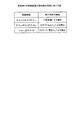
図4は、実施例1の歪補償テーブルの一例を示す図である。図4に示すように、歪補償テーブル123では、例えば、アドレスanに対して、振幅成分係数αn及び位相成分係数βnのペアが対応づけられている。振幅成分係数の値及び位相成分係数の値は、各アドレスに対応した値となり、例えば、アドレス値が増加するに従って、対応する振幅成分係数の値及び位相成分係数の値も増加する。例えば、アドレス生成部122から指定されたアドレスがa2の場合、歪補償テーブル123は、振幅成分係数としてα2を、位相成分係数としてβ2をPD部121へ出力する。
FIG. 4 is a diagram illustrating an example of the distortion compensation table according to the first embodiment. As shown in FIG. 4, the distortion compensation table 123, for example, the address a n, a pair of the amplitude component coefficient alpha n and the phase component coefficient beta n is associated. The value of the amplitude component coefficient and the value of the phase component coefficient become values corresponding to each address. For example, as the address value increases, the value of the corresponding amplitude component coefficient and the value of the phase component coefficient also increase. For example, when the address designated by the
PD部121は、歪補償テーブル123から入力された歪補償係数を用いて、送信ベースバンド信号x(t)に対してPDを施す。例えば、PD部121は、送信ベースバンド信号x(t)に歪補償係数を乗算し、乗算後の信号をPD信号y(t)としてDAC13へ出力する。上記の通り、歪補償係数は振幅成分係数及び位相成分係数を含むので、PD部121で行われるPDにより、送信ベースバンド信号x(t)の振幅成分及び位相成分の双方に対して歪補償が行われる。よって、PD部121によって行われるPDにより、PA17での増幅後の信号に生じる振幅歪及び位相歪の双方が補償される。
The
誤差算出部124は、送信ベースバンド信号x(t)とフィードバック信号z(t)との誤差を算出し、算出した誤差を歪補償係数更新部125へ出力する。誤差算出部124によって算出される誤差は、振幅誤差及び位相誤差を含む。
The
歪補償係数更新部125は、例えばLMS(Least Mean Square)アルゴリズム等を用いて、誤差算出部124から入力された誤差を最小にする歪補償係数を算出する。歪補償係数更新部125は、歪補償テーブル123に格納されている複数の歪補償係数のうち、アドレス生成部122から入力されたアドレスに対応する歪補償係数を、算出した歪補償係数によって更新する。
The distortion compensation coefficient updating unit 125 calculates a distortion compensation coefficient that minimizes the error input from the
<無線装置の動作例>
図5は、実施例1の無線装置の動作例の説明に供する図である。図5に示すように、位相ずれの補正に用いられる補正方式の候補として、例えば、(1)移相器による補正と、(2)ゲート電圧Vgsによる補正と、(3)ドレイン電圧Vdsによる補正の3つの補正方式がある。
<Operation example of wireless device>
FIG. 5 is a diagram for explaining an operation example of the wireless device according to the first embodiment. As shown in FIG. 5, for example, (1) correction by the phase shifter, (2) correction by the gate voltage V gs , and (3) drain voltage V ds are candidates for the correction method used for correcting the phase shift. There are three correction methods of correction by:
ここで、(1)移相器による補正(以下では「補正方式(1)」と呼ぶことがある)とは、移相器15によってPD信号の位相を変化させることにより位相ずれを補正するものである。位相ずれ補正部24は、移相器による補正を行う場合は、移相器15を制御して、PD信号の位相を所定量Δφ(1)だけ変化させることにより、位相ずれを所定量Δφ(1)だけ補正する。位相ずれ補正部24は、位相ずれ量算出部23で算出されたずれ量が+Δφ(t)であるときは、PD信号の位相を−Δφ(1)だけ変化させ、位相ずれ量算出部23で算出されたずれ量が−Δφ(t)であるときは、PD信号の位相を+Δφ(1)だけ変化させる。補正方式(1)の補正を用いた場合の消費電力は、例えば、所定量P(1)である。
Here, (1) correction by the phase shifter (hereinafter sometimes referred to as “correction method (1)”) is to correct the phase shift by changing the phase of the PD signal by the
また、(2)ゲート電圧Vgsによる補正(以下では「補正方式(2)」と呼ぶことがある)とは、PA17のゲート電圧Vgsを増加させることにより位相ずれを補正するものである。ゲート電圧Vgsを増加させると、PA17において発生する位相ずれが減少する。位相ずれ補正部24は、ゲート電圧Vgsによる補正を行う場合は、PA17のゲート電圧Vgsを所定量ΔVAだけ増加させることにより、位相ずれを所定量Δφ(2)だけ補正する。補正方式(2)の補正を用いた場合の消費電力は、例えば、所定量P(2)である。
Further, (2) correction by the gate voltage V gs (hereinafter sometimes referred to as “correction method (2)”) is to correct the phase shift by increasing the gate voltage V gs of the PA 17. When the gate voltage V gs is increased, the phase shift generated in the
また、(3)ドレイン電圧Vdsによる補正(以下では「補正方式(3)」と呼ぶことがある)とは、PA17のドレイン電圧Vdsを増加させることにより位相ずれを補正するものである。ドレイン電圧Vdsを増加させると、PA17において発生する位相ずれが減少する。位相ずれ補正部24は、ドレイン電圧Vdsによる補正を行う場合は、PA17のドレイン電圧Vdsを所定量ΔVBだけ増加させることにより、位相ずれを所定量Δφ(3)だけ補正する。補正方式(3)の補正を用いた場合の消費電力は、例えば、所定量P(3)である。
Further, (3) correction by the drain voltage V ds (hereinafter sometimes referred to as “correction method (3)”) is to correct the phase shift by increasing the drain voltage V ds of the PA 17. When the drain voltage V ds is increased, the phase shift generated in the
ここで、上記の3つの補正方式間での、補正量と、消費電力と、ベースバンド信号x(t)の位相変化に対する追従速度との関係は、例えば図5に示すようになっている。 Here, the relationship among the correction amount, the power consumption, and the tracking speed with respect to the phase change of the baseband signal x (t) between the above three correction methods is as shown in FIG. 5, for example.
すなわち、上記3つの補正方式間で補正量を比較すると、補正量の関係は、「補正方式(1)<補正方式(2)<補正方式(3)」である。つまり、「Δφ(1)<Δφ(2)<Δφ(3)」である。 That is, when the correction amounts are compared among the three correction methods, the relationship between the correction amounts is “correction method (1) <correction method (2) <correction method (3)”. That is, “Δφ (1) <Δφ (2) <Δφ (3) ”.
また、上記3つの補正方式間で消費電力を比較すると、消費電力の関係は、「補正方式(1)<補正方式(2)<補正方式(3)」である。つまり、「P(1)<P(2)<P(3)」である。 Further, when the power consumption is compared among the three correction methods, the relationship of power consumption is “correction method (1) <correction method (2) <correction method (3)”. That is, “P (1) <P (2) <P (3) ”.
また、上記3つの補正方式間で上記の追従速度を比較すると、追従速度の関係は、補正方式(1)よりも、補正方式(2)及び補正方式(3)の方が速く、補正方式(2)と補正方式(3)とは同等ある。 Further, when the following speeds are compared among the three correction methods, the relationship between the following speeds is faster in the correction method (2) and the correction method (3) than in the correction method (1). 2) and the correction method (3) are equivalent.
つまり、補正方式(1)〜(3)は、補正量及び消費電力が互いに異なる3つの補正方式である。また、補正方式(1)〜(3)は、補正量が大きいほど消費電力が大きい3つの補正方式である。つまり、補正方式(1)〜(3)の間では、補正量と消費電力とがトレードオフの関係にある。 That is, the correction methods (1) to (3) are three correction methods having different correction amounts and power consumptions. Further, the correction methods (1) to (3) are three correction methods in which the power consumption increases as the correction amount increases. That is, between the correction methods (1) to (3), the correction amount and the power consumption are in a trade-off relationship.
位相ずれ補正部24は、補正方式(1)〜(3)のうち、位相ずれ量算出部23によって算出されたずれ量に応じた補正方式を用いて、送信ベースバンド信号x(t)に対するフィードバック信号z(t)の位相ずれを補正する。ここで、「ずれ量に応じた補正方式」なる文言は、位相ずれ量算出部23によって算出されたずれ量に応じてカウントされるレジスタ値に対応する補正方式などの様に、「位相ずれ量算出部23によって算出されたずれ量」と「補正方式」とを間接的に関係付ける実施形態をも含む概念として、本明細書では用いられることに留意されたい。
The phase
<無線装置の処理例>
図6は、実施例1の無線装置の処理例の説明に供するフローチャートである。図6に示すフローチャートは、例えば、一定の周期で到来する制御タイミング毎に開始される。つまり、制御タイミングが訪れる度に、図6に示す一連の処理が実行される。例えば、この制御タイミングは、歪補償係数の更新タイミングの直後に設定される。
<Processing example of wireless device>
FIG. 6 is a flowchart for explaining a processing example of the wireless apparatus according to the first embodiment. The flowchart shown in FIG. 6 is started at each control timing that arrives at a constant cycle, for example. That is, every time the control timing comes, a series of processing shown in FIG. 6 is executed. For example, the control timing is set immediately after the distortion compensation coefficient update timing.
ステップS201では、電力算出部25は、フィードバック信号z(t)の電力値Pz(t)を算出し、算出した電力値Pz(t)を位相ずれ量算出部23及び位相ずれ補正部24へ出力する(ステップS201)。
In step S <b> 201, the power calculation unit 25 calculates the power value P z (t) of the feedback signal z (t), and uses the calculated power value P z (t) as the phase shift
ステップS203では、位相ずれ量算出部23及び位相ずれ補正部24は、電力値Pz(t)と閾値Pthとを比較する閾値判定を行う(ステップS203)。
In step S203, the phase shift
電力値Pz(t)が閾値Pth以上であるときは(ステップS203:Yes)、ステップS205において、位相ずれ量算出部23は、位相ずれのずれ量Δφ(t)を算出し、算出したずれ量Δφ(t)を位相ずれ補正部24へ出力する(ステップS205)。一方で、電力値Pz(t)が閾値Pth未満であるときは(ステップS203:No)、位相ずれ量算出部23は、ずれ量Δφ(t)の算出を行わない。
When the power value P z (t) is equal to or greater than the threshold value P th (step S203: Yes), in step S205, the phase shift
また、電力値Pz(t)が閾値Pth以上であるときは(ステップS203:Yes)、ステップS205の処理後、ステップS207において、位相ずれ補正部24は、ずれ量の絶対値|Δφ(t)|と閾値φthとを比較する閾値判定を行う(ステップS207)。
When the power value P z (t) is equal to or greater than the threshold value P th (step S203: Yes), after the process of step S205, in step S207, the phase
絶対値|Δφ(t)|が閾値φth以上であるときは(ステップS207:Yes)、位相ずれ補正部24は、位相ずれ補正部24が有するレジスタ(図示せず)の値を確認する(ステップS209)。
When the absolute value | Δφ (t) | is equal to or greater than the threshold φ th (step S207: Yes), the phase
ここで、位相ずれ補正部24が有するレジスタの値は、各補正方式に対応する。例えば、レジスタ値=‘1’は補正方式(1)に対応し、レジスタ値=‘2’は補正方式(2)に対応し、レジスタ値=‘3’は補正方式(3)に対応する。よって、ステップS209でのレジスタ値の確認は、前回の制御タイミングで用いられた補正方式の確認に相当する。また、レジスタ値が‘0’であることは、前回の制御タイミングで位相ずれの補正が行われなかったことを示す。また、上記のように、補正方式の候補が補正方式(1)〜(3)の3つである場合は、レジスタ値の最大値は‘3’に設定される。
Here, the value of the register included in the phase
次いでステップS211では、位相ずれ補正部24は、レジスタ値が最大値未満か否かを判断する(ステップS211)。レジスタ値が最大値未満のときは(ステップS211:Yes)、位相ずれ補正部24は、レジスタ値をインクリメントする、つまり、レジスタ値を1増やす(ステップS213)。一方、レジスタ値が最大値以上のとき、つまり、レジスタ値が最大値に達しているときは(ステップS211:No)、位相ずれ補正部24はステップS213の処理を行わずに、処理はステップS215へ進む。
Next, in step S211, the phase
ステップS215では、位相ずれ補正部24は、レジスタ値に対応する補正方式を用いて位相ずれを補正する(ステップS215)。ステップS215の処理後、当該制御タイミングでの処理は終了する。
In step S215, the phase
電力値Pz(t)が閾値Pth未満であるとき(ステップS203:No)、または、絶対値|Δφ(t)|が閾値φth未満であるときは(ステップS207:No)、位相ずれ補正部24は、位相ずれの補正を行わずに、レジスタ値を‘0’にリセットする。ステップS217の処理後、当該制御タイミングでの処理は終了する。
When the power value P z (t) is less than the threshold value P th (step S203: No), or when the absolute value | Δφ (t) | is less than the threshold value φ th (step S207: No), the phase shift The correcting
以下、補正方式の候補が上記のように補正方式(1)〜(3)である場合の無線装置1の処理の一例について説明する。補正方式の候補が補正方式(1)〜(3)であるため、レジスタ値の最大値は‘3’である。また、以下の制御タイミングt1〜t4の何れにおいても、Pz(t)がPth以上であるとする。 Hereinafter, an example of processing of the wireless device 1 when the correction method candidates are the correction methods (1) to (3) as described above will be described. Since the correction method candidates are the correction methods (1) to (3), the maximum value of the register value is “3”. In addition, at any of the following control timings t1 to t4, it is assumed that Pz (t) is equal to or greater than Pth .
<制御タイミングt1での処理>
制御タイミングt1の到来時、レジスタ値は‘0’であるとする。|Δφ(t)|がφth以上であると、位相ずれ補正部24は、レジスタ値をインクリメントしてレジスタ値を‘1’にする。そして、位相ずれ補正部24は、レジスタ値=‘1’に対応する補正方式(1)を用いて位相ずれを補正する。つまり、位相ずれ補正部24は、移相器15を制御して、PD信号の位相を所定量Δφ(1)だけ変化させることにより、位相ずれを所定量Δφ(1)だけ補正する。補正方式(1)を用いた補正により、位相ずれは、所定量Δφ(1)だけ抑圧される。
<Processing at control timing t1>
It is assumed that the register value is “0” when the control timing t1 arrives. If | Δφ (t) | is equal to or greater than φth , the phase
<制御タイミングt2での処理>
制御タイミングt1で補正方式(1)により位相ずれの補正が行われた場合、制御タイミングt1の次の制御タイミングである制御タイミングt2の到来時には、レジスタ値は‘1’になっている。また、制御タイミングt1での処理により、位相ずれは、位相ずれの補正が行われていない当初と比べて、所定量Δφ(1)だけ抑圧されている。
<Processing at control timing t2>
When the phase shift is corrected by the correction method (1) at the control timing t1, the register value is “1” when the control timing t2, which is the control timing next to the control timing t1, arrives. Further, by the processing at the control timing t1, the phase shift is suppressed by a predetermined amount Δφ (1) compared to the initial time when the phase shift is not corrected.
制御タイミングt1で補正方式(1)により位相ずれが所定量Δφ(1)だけ抑圧された後も|Δφ(t)|がφth以上であると、位相ずれ補正部24は、レジスタ値をインクリメントしてレジスタ値を‘2’にする。そして、位相ずれ補正部24は、補正方式(1)に替えて、レジスタ値=‘2’に対応する補正方式(2)を用いて位相ずれを補正する。つまり、位相ずれ補正部24は、PA17のゲート電圧Vgsを所定量ΔVAだけ増加させることにより、位相ずれを所定量Δφ(2)だけ補正する。補正方式(2)を用いた補正により、位相ずれは、所定量Δφ(2)だけ抑圧される。
Phase shift by the correction method (1) in control timing t1 even after being suppressed by a predetermined amount [Delta] [phi (1) | [Delta] [phi (t) | When it is the phi th or more, the phase
一方で、制御タイミングt1で補正方式(1)により位相ずれが所定量Δφ(1)だけ抑圧された結果|Δφ(t)|がφth未満になる場合は、位相ずれ補正部24は、位相ずれの補正を行わずに、レジスタ値を‘0’にリセットする。補正方式(1)により位相ずれが所定量Δφ(1)だけ抑圧された結果|Δφ(t)|がφth未満になる場合は、制御タイミングt1における補正前の|Δφ(t)|はφth以上かつΔφ(1)未満であったことになる。
On the other hand, the phase shift by the correction method (1) in control timing t1, a predetermined amount [Delta] [phi (1) only oppressed result | [Delta] [phi (t) | If is less than phi th, the phase
<制御タイミングt3での処理>
制御タイミングt2で補正方式(2)により位相ずれの補正が行われた場合、制御タイミングt2の次の制御タイミングである制御タイミングt3の到来時には、レジスタ値は‘2’になっている。また、制御タイミングt2での処理により、位相ずれは、位相ずれの補正が行われていない当初と比べて、所定量Δφ(2)だけ抑圧されている。
<Processing at control timing t3>
When the phase shift is corrected by the correction method (2) at the control timing t2, the register value is “2” when the control timing t3, which is the control timing next to the control timing t2, arrives. Further, by the processing at the control timing t2, the phase shift is suppressed by a predetermined amount Δφ (2) compared to the initial time when the phase shift is not corrected.
制御タイミングt2で補正方式(2)により位相ずれが所定量Δφ(2)だけ抑圧された後も|Δφ(t)|がφth以上であると、位相ずれ補正部24は、レジスタ値をインクリメントしてレジスタ値を‘3’にする。そして、位相ずれ補正部24は、補正方式(2)に替えて、レジスタ値=‘3’に対応する補正方式(3)を用いて位相ずれを補正する。つまり、位相ずれ補正部24は、PA17のドレイン電圧Vdsを所定量ΔVBだけ増加させることにより、位相ずれを所定量Δφ(3)だけ補正する。補正方式(3)を用いた補正により、位相ずれは、所定量Δφ(3)だけ抑圧される。
Phase shift by the correction method (2) in control timing t2 even after being suppressed by a predetermined amount [Delta] [phi (2) | [Delta] [phi (t) | When it is the phi th or more, the phase
一方で、制御タイミングt2で補正方式(2)により位相ずれが所定量Δφ(2)だけ抑圧された結果|Δφ(t)|がφth未満になる場合は、位相ずれ補正部24は、位相ずれの補正を行わずに、レジスタ値を‘0’にリセットする。補正方式(2)により位相ずれが所定量Δφ(2)だけ抑圧された結果|Δφ(t)|がφth未満になる場合は、制御タイミングt1における補正前の|Δφ(t)|はΔφ(1)以上かつΔφ(2)未満であったことになる。
On the other hand, the phase shift by the correction method (2) in control timing t2 is a predetermined amount [Delta] [phi (2) only oppressed result | [Delta] [phi (t) | If is less than phi th, the phase
<制御タイミングt4での処理>
制御タイミングt3で補正方式(3)により位相ずれの補正が行われた場合、制御タイミングt3の次の制御タイミングである制御タイミングt4の到来時には、レジスタ値は最大値である‘3’になっている。また、制御タイミングt3での処理により、位相ずれは、位相ずれの補正が行われていない当初と比べて、所定量Δφ(3)だけ抑圧されている。
<Processing at control timing t4>
When the phase shift is corrected by the correction method (3) at the control timing t3, when the control timing t4, which is the control timing next to the control timing t3, arrives, the register value becomes the maximum value “3”. Yes. Further, by the processing at the control timing t3, the phase shift is suppressed by a predetermined amount Δφ (3) compared to the initial time when the phase shift is not corrected.
制御タイミングt3で補正方式(3)により位相ずれが所定量Δφ(3)だけ抑圧された後も|Δφ(t)|がφth以上であると、位相ずれ補正部24は、レジスタ値が最大値の‘3’であるため、引き続き補正方式(3)を用いて位相ずれを補正する。
Phase shift by the correction method (3) in the control timing t3 even after being suppressed by a predetermined amount [Delta] [phi (3) | [Delta] [phi (t) | When it is the phi th or more, the phase
一方で、制御タイミングt3で、補正方式(3)により位相ずれが所定量Δφ(3)だけ抑圧された結果|Δφ(t)|がφth未満になる場合は、位相ずれ補正部24は、位相ずれの補正を行わずに、レジスタ値を‘0’にリセットする。補正方式(3)により位相ずれが所定量Δφ(3)だけ抑圧された結果|Δφ(t)|がφth未満になる場合は、制御タイミングt1における補正前の|Δφ(t)|はΔφ(2)以上かつΔφ(3)未満であったことになる。
On the other hand, the control timing t3, the phase shift by the correction method (3) is a predetermined amount [Delta] [phi (3) only oppressed result | [Delta] [phi (t) | If is less than phi th, the phase
以上、無線装置1の処理の一例について説明した。 Heretofore, an example of processing of the wireless device 1 has been described.
ここで、例えば、閾値Pthは、PA17の定格出力に等しい値に設定されるのが好ましい。通常、定格出力は、PA17における位相ずれが生じ始める電力付近に設定されることが多いからである。
Here, for example, the threshold value P th is preferably set to a value equal to the rated output of the
また、例えば、閾値φthは、歪補償部12の歪補償能力に応じた値に設定されるのが好ましい。例えば、閾値φthは、歪補償部12で補償可能な最大の位相歪に対応する値に設定される。
Further, for example, the threshold φ th is preferably set to a value corresponding to the distortion compensation capability of the
以上のように、実施例1では、無線装置1は、増幅部16と、位相ずれ量算出部23と、位相ずれ補正部24とを有する。増幅部16は、信号の電力を増幅する。位相ずれ量算出部23は、増幅部16での増幅前の信号に対する、増幅部16での増幅後の信号の位相ずれのずれ量を算出する。位相ずれ補正部24は、補正方式(1)〜(3)のうち、位相ずれ量算出部23によって算出されたずれ量に応じた補正方式を用いて位相ずれを補正する。補正方式(2)は、補正方式(1)よりも、補正量及び消費電力が大きい。また、補正方式(3)は、補正方式(1)及び補正方式(2)よりも、補正量及び消費電力が大きい。
As described above, in the first embodiment, the wireless device 1 includes the amplification unit 16, the phase shift
こうすることで、位相ずれのずれ量が小さいときは、補正量が小さく、かつ、消費電力も小さい補正方式を用いて位相ずれを補正できる。一方で、位相ずれのずれ量が大きいときは、補正量が大きく、かつ、消費電力も大きい補正方式を用いて位相ずれを補正できる。よって、実施例1によれば、最低限の消費電力で位相ずれのずれ量をPDの歪補償能力の範囲内にし得るので、最低限の消費電力でACLRを改善できる。 In this way, when the amount of phase shift is small, the phase shift can be corrected using a correction method with a small correction amount and low power consumption. On the other hand, when the shift amount of the phase shift is large, the phase shift can be corrected using a correction method in which the correction amount is large and the power consumption is large. Therefore, according to the first embodiment, the shift amount of the phase shift can be within the range of the PD distortion compensation capability with the minimum power consumption, so that the ACLR can be improved with the minimum power consumption.
また、実施例1では、位相ずれ補正部24は、算出された|Δφ(t)|がφth以上のときに、補正量Δφ(1)と消費電力P(1)とを有する補正方式(1)を用いて位相ずれを補正する。また、位相ずれ補正部24は、補正方式(1)を用いた補正の後に算出された|Δφ(t)|がφth以上のときに、補正方式(1)に替えて、補正量Δφ(2)と消費電力P(2)とを有する補正方式(2)を用いて位相ずれを補正する。また、位相ずれ補正部24は、補正方式(2)を用いた補正の後に算出された|Δφ(t)|がφth以上のときに、補正方式(2)に替えて、補正量Δφ(3)と消費電力P(3)とを有する補正方式(3)を用いて位相ずれを補正する。
In Example 1, the phase
こうすることで、位相ずれのずれ量をPDの歪補償能力の範囲内にするにあたって、位相ずれのずれ量に対する閾値を1つだけ設定すればよいため、ずれ量に対する閾値の設定が容易になって、無線装置の開発作業の負荷を軽減することができる。 This makes it easy to set the threshold value for the shift amount because only one threshold value for the shift amount of the phase shift needs to be set in order to set the shift amount of the phase shift within the range of the distortion compensation capability of the PD. Thus, it is possible to reduce the load of wireless device development work.
また、実施例1では、閾値φthは、歪補償部12の歪補償能力に基づいて設定される。
In the first embodiment, the threshold φ th is set based on the distortion compensation capability of the
こうすることで、歪補償部12の歪補償能力が高い場合は閾値φthを大きく設定し、歪補償部12の歪補償能力が低い場合は閾値φthを小さく設定することができるので、位相ずれのずれ量に対して最適な閾値を設定できる。
In this way, when the distortion compensation capability of the
また、実施例1では、位相ずれ補正部24は、増幅後の信号の電力値が閾値Pth以上のときに位相ずれの補正を行い、増幅後の信号の電力値が閾値Pth未満のときに位相ずれの補正を行わない。
In the first embodiment, the phase
こうすることで、増幅後の信号の電力値が閾値未満の領域、例えば、位相ずれが発生しない領域における補正処理を省くことができるため、消費電力を削減できる。 By doing so, it is possible to omit correction processing in a region where the power value of the amplified signal is less than the threshold value, for example, a region where no phase shift occurs, so that power consumption can be reduced.
[実施例2]
<無線装置の動作例>
図7は、実施例2の無線装置の動作例の説明に供する図である。実施例2では、図7に示すように、補正方式(1)〜(3)が、位相ずれのずれ量の絶対値|Δφ(t)|の3つの閾値範囲(a)〜(c)と対応付けられている。図7に示す閾値φthは、実施例1の閾値φthと同一である。また、図7に示す各閾値の大小関係は、φth<φth1<φth2である。
[Example 2]
<Operation example of wireless device>
FIG. 7 is a diagram for explaining an operation example of the wireless apparatus according to the second embodiment. In the second embodiment, as shown in FIG. 7, the correction methods (1) to (3) include three threshold ranges (a) to (c) of absolute values | Δφ (t) | It is associated. The threshold φ th shown in FIG. 7 is the same as the threshold φ th of the first embodiment. Further, the magnitude relationship between the threshold values shown in FIG. 7 is φ th <φ th1 <φ th2 .
位相ずれ補正部24は、補正方式(1)〜(3)のうち、位相ずれのずれ量に応じた補正方式を用いて位相ずれを補正する。このために、位相ずれ補正部24は、閾値範囲(a)〜(c)のうちで、ずれ量の絶対値|Δφ(t)|が該当する閾値範囲に対応する補正方式を用いて位相ずれを補正する。例えば、ずれ量の絶対値|Δφ(t)|がφth以上で、かつ、φth1未満のときは、位相ずれ補正部24は、補正方式(1)を用いて位相ずれを補正する。また、ずれ量の絶対値|Δφ(t)|がφth1以上で、かつ、φth2未満のときは、位相ずれ補正部24は、補正方式(2)を用いて位相ずれを補正する。また、ずれ量の絶対値|Δφ(t)|がφth2以上のときは、位相ずれ補正部24は、補正方式(3)を用いて位相ずれを補正する。なお、ずれ量の絶対値|Δφ(t)|がφth未満のときは、実施例1と同様に、位相ずれ補正部24は、位相ずれの補正を行わない。
The phase
ここで、実施例2では、各補正方式の補正量は、例えば、Δφ(1)=φth1,Δφ(2)=φth2,Δφ(3)>φth2に設定される。 Here, in Example 2, the correction amount of each correction method is set to, for example, Δφ (1) = φ th1 , Δφ (2) = φ th2 , Δφ (3) > φ th2 .
<無線装置の処理例>
図8は、実施例2の無線装置の処理例の説明に供するフローチャートである。図8に示すフローチャートは、例えば、実施例1と同様に、一定の周期で到来する制御タイミング毎に開始される。つまり、制御タイミングが訪れる度に、図8に示す一連の処理が実行される。例えば、この制御タイミングは、歪補償係数の更新タイミングの直後に設定される。
<Processing example of wireless device>
FIG. 8 is a flowchart for explaining a processing example of the wireless device according to the second embodiment. The flowchart shown in FIG. 8 is started at each control timing that arrives at a constant cycle, for example, as in the first embodiment. That is, each time the control timing comes, a series of processes shown in FIG. 8 are executed. For example, the control timing is set immediately after the distortion compensation coefficient update timing.
図8において、ステップS201〜S207の処理については、実施例1と同一であるため、説明を省略する。 In FIG. 8, the processes in steps S201 to S207 are the same as those in the first embodiment, and thus the description thereof is omitted.
ステップS207における閾値判定の結果、絶対値|Δφ(t)|が閾値φth以上であるときは(ステップS207:Yes)、位相ずれ補正部24は、次の判断を行う。すなわち、位相ずれ補正部24は、絶対値|Δφ(t)|が閾値φth以上であるときは(ステップS207:Yes)、絶対値|Δφ(t)|が、図7に示す3つの閾値範囲(a)〜(c)の何れに該当するかを判断する(ステップS301)。
As a result of the threshold determination in step S207, when the absolute value | Δφ (t) | is equal to or greater than the threshold φth (step S207: Yes), the phase
位相ずれ補正部24は、絶対値|Δφ(t)|が閾値範囲(a)に該当すると判断したときは、補正方式(1)を用いて位相ずれを補正する(ステップS303)。
When the phase
また、位相ずれ補正部24は、絶対値|Δφ(t)|が閾値範囲(b)に該当すると判断したときは、補正方式(2)を用いて位相ずれを補正する(ステップS305)。
When the phase
また、位相ずれ補正部24は、絶対値|Δφ(t)|が閾値範囲(c)に該当すると判断したときは、補正方式(3)を用いて位相ずれを補正する(ステップS307)。
When the phase
ステップS303,S305,S307の処理後、当該制御タイミングでの処理は終了する。 After the processes in steps S303, S305, and S307, the process at the control timing ends.
電力値Pz(t)が閾値Pth未満であるとき(ステップS203:No)、または、絶対値|Δφ(t)|が閾値φth未満であるときは(ステップS207:No)、位相ずれ補正部24は位相ずれの補正を行わずに、当該制御タイミングでの処理は終了する。
When the power value P z (t) is less than the threshold value P th (step S203: No), or when the absolute value | Δφ (t) | is less than the threshold value φ th (step S207: No), the phase shift The
以上のように、実施例2では、無線装置1は、増幅部16と、位相ずれ量算出部23と、位相ずれ補正部24とを有する。増幅部16は、信号の電力を増幅する。位相ずれ量算出部23は、増幅部16での増幅前の信号に対する、増幅部16での増幅後の信号の位相ずれのずれ量を算出する。位相ずれ補正部24は、補正方式(1)〜(3)のうち、位相ずれ量算出部23によって算出されたずれ量に応じた補正方式を用いて位相ずれを補正する。補正方式(2)は、補正方式(1)よりも、補正量及び消費電力が大きい。また、補正方式(3)は、補正方式(1)及び補正方式(2)よりも、補正量及び消費電力が大きい。
As described above, in the second embodiment, the wireless device 1 includes the amplification unit 16, the phase shift
こうすることで、位相ずれのずれ量が小さいときは、補正量が小さく、かつ、消費電力も小さい補正方式を用いて位相ずれを補正できる。一方で、位相ずれのずれ量が大きいときは、補正量が大きく、かつ、消費電力も大きい補正方式を用いて位相ずれを補正できる。よって、実施例2によれば、最低限の消費電力で位相ずれのずれ量をPDの歪補償能力の範囲内にし得るので、最低限の消費電力でACLRを改善できる。 In this way, when the amount of phase shift is small, the phase shift can be corrected using a correction method with a small correction amount and low power consumption. On the other hand, when the shift amount of the phase shift is large, the phase shift can be corrected using a correction method in which the correction amount is large and the power consumption is large. Therefore, according to the second embodiment, the shift amount of the phase shift can be within the range of the PD distortion compensation capability with the minimum power consumption, so that the ACLR can be improved with the minimum power consumption.
また、実施例2では、補正方式(1)〜(3)は、ずれ量の絶対値|Δφ(t)|の閾値範囲(a)〜(c)とそれぞれ対応付けられている。位相ずれ補正部24は、閾値範囲(a)〜(c)のうちで|Δφ(t)|が該当する閾値範囲に対応する補正方式を用いて位相ずれを補正する。
In the second embodiment, the correction methods (1) to (3) are respectively associated with threshold ranges (a) to (c) of the absolute value | Δφ (t) | The phase
実施例1では、上記のように、位相ずれのずれ量に対する閾値を1つだけ設定すればよいため、ずれ量に対する閾値の設定が容易になって、無線装置の開発作業の負荷を軽減することができる。一方で、実施例1では、位相ずれのずれ量が大きい場合には、位相ずれのずれ量がPDの歪補償能力の範囲内に抑圧されるまでに、複数回の制御タイミングに渡ってずれ量の絶対値に対する閾値判定が繰り返されることがある。このため、実施例1では、位相ずれのずれ量がPDの歪補償能力の範囲内に抑圧されるまでに長時間かかることがある。これに対し、実施例2では、上記のように補正方式(1)〜(3)と閾値範囲(a)〜(c)とを対応付けることで、位相ずれのずれ量の大きさにかかわらず、ずれ量をPDの歪補償能力の範囲内に抑圧する補正方式を1回の制御タイミングで決定することができる。よって、実施例2によれば、実施例1と比較して、低消費電力化を図ることができる。 In the first embodiment, as described above, it is only necessary to set one threshold for the amount of phase shift, and therefore, it becomes easy to set the threshold for the amount of shift, thereby reducing the load of development work of the wireless device. Can do. On the other hand, in the first embodiment, when the amount of phase deviation is large, the amount of deviation over a plurality of control timings until the amount of phase deviation is suppressed within the range of the distortion compensation capability of the PD. The threshold determination for the absolute value of may be repeated. For this reason, in the first embodiment, it may take a long time for the phase shift amount to be suppressed within the range of the distortion compensation capability of the PD. On the other hand, in the second embodiment, the correction methods (1) to (3) and the threshold ranges (a) to (c) are associated with each other as described above, regardless of the magnitude of the phase shift amount. A correction method for suppressing the deviation amount within the range of the distortion compensation capability of the PD can be determined at a single control timing. Therefore, according to the second embodiment, power consumption can be reduced as compared with the first embodiment.
[実施例3]
実施例3では、増幅部の構成が実施例1及び実施例2と相違する。
[Example 3]
In the third embodiment, the configuration of the amplification unit is different from the first and second embodiments.
<増幅部の構成例>
図9は、実施例3の増幅部の構成例を示すブロック図である。実施例1及び実施例2では、増幅部16がPA17の一段のアンプを有する場合を例示した。これに対し、図9に示すように、実施例3の増幅部30は、例えば、互いに直接に接続されたPA31、PA32及びPA33の三段のアンプを有する。つまり、PA31は、アップコンバート後のPD信号の電力を増幅し、増幅後の信号をPA32へ出力する。PA32は、PA31での増幅後の信号の電力をさらに増幅し、増幅後の信号を、移相器15を介してPA33へ出力する。PA33は、PA32での増幅後の信号の電力をさらに増幅し、増幅後の信号をカプラ18へ出力する。
<Configuration example of amplification unit>
FIG. 9 is a block diagram illustrating a configuration example of the amplification unit according to the third embodiment. In the first and second embodiments, the case where the amplifying unit 16 includes a one-stage amplifier of the
増幅部30がPA31、PA32及びPA33の三段のアンプを有する場合、PA31,PA32,PA33の各々において入出力信号間の位相ずれが発生する。このため、PA32から出力される信号には、PA32での位相ずれだけでなく、PA31での位相ずれも含まれる。また、PA33から出力される信号には、PA33での位相ずれだけでなく、PA31及びPA32での位相ずれも含まれる。また、歪補償部12では、PA31、PA32及びPA33のすべてでの非線形歪が一括して補償される。
When the amplifying
よって、PA31,PA32,PA33の各アンプに対して個別に位相ずれの補正を行うのではなく、最終段のアンプであるPA33に対する位相ずれの補正において、PA31、PA32及びPA33でのすべての位相ずれを一括して補正するのが効率的である。 Therefore, instead of individually correcting the phase shift for each of the amplifiers PA31, PA32, and PA33, all the phase shifts in the PA31, PA32, and PA33 are corrected in the phase shift correction for the PA33 that is the final stage amplifier. It is efficient to correct for all of them.
また、増幅部が多段の複数のPAを有する場合、最終段以外のPAを線形領域で動作させる一方で、最終段のPAを飽和領域付近で動作させることが多い。 In addition, when the amplifying unit includes a plurality of multistage PAs, the PAs other than the final stage are operated in the linear region, while the final stage PA is often operated in the vicinity of the saturation region.
そこで、位相ずれ補正部24は、PA31、PA32及びPA33の三段のアンプのうち、最終段のアンプであるPA33に対してだけ位相ずれの補正を行う。すなわち、移相器15は、PA32の後段、かつ、PA33の前段に配置され、位相ずれ補正部24の制御の下で、PA32から出力される信号の位相を、実施例1または実施例2と同様にして変化させる。また、位相ずれ補正部24は、実施例1または実施例2と同様にして、移相器15、PA33のゲート電圧Vgs、及び、PA33のドレイン電圧Vdsを制御することによって位相ずれを補正する。
Therefore, the phase
以上のように、実施例3では、増幅部30は、多段に直列に接続された複数のアンプ(例えば、PA31,PA32,PA33)を有する。位相ずれ補正部24は、多段に直列に接続された複数のアンプのうち、最終段のアンプ(例えば、PA33)に対してだけ位相ずれの補正を行う。
As described above, in the third embodiment, the amplifying
こうすることで、増幅部が多段のPAを有する無線装置において、位相ずれの補正を効率的に行うことができる。 By so doing, it is possible to efficiently correct the phase shift in a radio apparatus in which the amplification unit has a multistage PA.
[実施例4]
実施例4では、増幅部の構成が実施例1及び実施例2と相違する。
[Example 4]
In the fourth embodiment, the configuration of the amplifying unit is different from the first and second embodiments.
<増幅部の構成例>
図10は、実施例4の増幅部の構成例を示すブロック図である。図10において、増幅部40は、分配器41と、キャリアアンプ42と、ピークアンプ43と、インピーダンス変換器44とを有する。つまり、増幅部40は、ドハティ型の増幅部である。
<Configuration example of amplification unit>
FIG. 10 is a block diagram illustrating a configuration example of the amplification unit according to the fourth embodiment. In FIG. 10, the amplifying
分配器41は、アップコンバータ14から移相器15を介して入力されるPD信号の電力値が所定の閾値未満の場合は、キャリアアンプ42へのみPD信号を出力する。一方で、分配器41は、PD信号の電力値が所定の閾値以上の場合は、キャリアアンプ42及びピークアンプ43の双方へPD信号を出力する。
The
キャリアアンプ42は、入力電力が小さい場合における線形性を備えたアンプであり、分配器41から入力されたPD信号の電力を増幅し、増幅後の信号をインピーダンス変換器44へ出力する。これに対し、ピークアンプ43は、入力電力が大きい場合にのみ使用されるアンプであり、分配器41から入力されたPD信号の電力を増幅し、増幅後の信号をインピーダンス変換器44へ出力する。
The
インピーダンス変換器44は、分配器41に入力されたPD信号の電力値が所定の閾値未満の場合は、キャリアアンプ42からだけ信号を入力されるため、キャリアアンプ42から入力された信号をカプラ18へ出力する。
Since the
一方で、インピーダンス変換器44は、分配器41に入力されたPD信号の電力値が所定の閾値以上の場合は、キャリアアンプ42及びピークアンプ43の双方から信号を入力される。このため、インピーダンス変換器44は、キャリアアンプ42から入力された信号とピークアンプ43から入力された信号との間で出力インピーダンスを調整する。出力インピーダンスの調整後、インピーダンス変換器44は、キャリアアンプ42から入力された信号とピークアンプ43から入力された信号とを合成し、合成後の信号をカプラ18へ出力する。
On the other hand, the
このように、増幅部40は、入力電力が小さい場合はキャリアアンプ42からの信号のみで出力信号を生成し、入力電力が大きい場合はキャリアアンプ42からの信号とピークアンプ43からの信号とを合成して出力信号を生成する。よって、増幅部40の特性は、入力電力が小さい場合はキャリアアンプ42の特性と一致し、入力電力が大きい場合は、キャリアアンプ42の特性とピークアンプ43の特性とを合成したものになる。
As described above, the amplifying
ここで、キャリアアンプ42は、入力電力が小さい場合での線形性を有するが、入力電力が大きい場合での線形性を有しない。これに対し、上記のように、ピークアンプ43は、増幅部40への入力電力が大きい場合にのみ使用される一方で、キャリアアンプ42は、増幅部40への入力電力が小さい場合にも大きい場合にも使用される。つまり、ピークアンプ43は位相ずれが増大する飽和領域で使用される一方で、キャリアアンプ42は、線形領域でも、位相ずれが増大する飽和領域でも使用される。
Here, the
そこで、位相ずれ補正部24は、キャリアアンプ42及びピークアンプ43の双方に対して位相ずれの補正を行う。すなわち、移相器15は、分配器41の前段に配置され、位相ずれ補正部24の制御の下で、アップコンバータ14から出力される信号の位相を、実施例1または実施例2と同様にして変化させる。また、位相ずれ補正部24は、実施例1または実施例2と同様にして、移相器15と、キャリアアンプ42及びピークアンプ43のゲート電圧Vgsと、キャリアアンプ42及びピークアンプ43のドレイン電圧Vdsとを制御することによって位相ずれを補正する。
Therefore, the phase
以上のように、実施例4では、増幅部40は、キャリアアンプ42とピークアンプ43とを有するドハティ型の増幅部である。位相ずれ補正部24は、キャリアアンプ42及びピークアンプ43の双方に対して位相ずれの補正を行う。
As described above, in the fourth embodiment, the
こうすることで、ドハティ型の増幅部を有する無線装置において、最低限の消費電力で位相ずれのずれ量をPDの歪補償能力の範囲内にし得るので、最低限の消費電力でACLRを改善できる。 In this way, in a wireless device having a Doherty-type amplification unit, the amount of phase shift can be within the range of the PD distortion compensation capability with the minimum power consumption, so that the ACLR can be improved with the minimum power consumption. .
ここで、ドハティ型の増幅部では、キャリアアンプ42とピークアンプ43とを比較すると、キャリアアンプ42の方が動作する割合が大きいため、位相ずれの補正の効果は、キャリアアンプ42に対するもの方が大きい。そこで、位相ずれ補正部24は、キャリアアンプ42とピークアンプ43のうち、キャリアアンプ42に対してだけ位相ずれの補正を行っても良い。こうすることで、ドハティ型の増幅部を有する無線装置において、位相ずれの補正を効率的に行うことができる。
Here, in the Doherty amplification unit, when the
[他の実施例]
[1]誤差算出部124が位相誤差を算出することにより、位相ずれのずれ量を算出することが可能である。よって、位相ずれのずれ量の算出を、位相ずれ量算出部23に代わって、誤差算出部124が行っても良い。
[Other embodiments]
[1] By calculating the phase error by the
[2]上記の実施例では、補正方式(1)〜(3)をそれぞれ単独で用いる場合について説明した。しかし、位相ずれ補正部24は、複数の補正方式を同時に用いて位相ずれを補正しても良い。例えば、位相ずれ補正部24は、補正方式(1)と補正方式(2)とを同時に用いても良く、また、補正方式(1)と補正方式(3)とを同時に用いても良い。補正方式(1)と補正方式(2)とが同時に用いられる場合の補正量及び消費電力は、補正方式(3)が単独で用いられる場合よりも大きい。また、補正方式(1)と補正方式(3)とが同時に用いられる場合の補正量及び消費電力は、補正方式(1)と補正方式(2)とが同時に用いられる場合よりも大きい。補正方式(1)と補正方式(2)とが同時に用いられる場合、補正方式(1)と補正方式(2)との組合せは、例えば、補正方式(4)に相当する。よって、補正方式(4)は、補正方式(3)よりも補正量及び消費電力が大きい。また、補正方式(1)と補正方式(3)とが同時に用いられる場合、補正方式(1)と補正方式(3)との組合せは、例えば、補正方式(5)に相当する。よって、補正方式(5)は、補正方式(4)よりも補正量及び消費電力が大きい。
[2] In the above embodiment, the case where the correction methods (1) to (3) are used individually has been described. However, the phase
[3]無線装置1は、例えば、次のようなハードウェア構成により実現することができる。図11は、無線装置のハードウェア構成例を示す図である。図11に示すように、無線装置1は、ハードウェアの構成要素として、プロセッサ51と、メモリ52と、無線通信モジュール53とを有する。プロセッサ51の一例として、CPU(Central Processing Unit),DSP(Digital Signal Processor),FPGA(Field Programmable Gate Array)等が挙げられる。また、無線装置1は、プロセッサ51と周辺回路とを含むLSI(Large Scale Integrated circuit)を有してもよい。メモリ52の一例として、SDRAM等のRAM,ROM,フラッシュメモリ等が挙げられる。
[3] The wireless device 1 can be realized by the following hardware configuration, for example. FIG. 11 is a diagram illustrating a hardware configuration example of the wireless device. As illustrated in FIG. 11, the wireless device 1 includes a
例えば、DAC13と、アップコンバータ14と、移相器15と、増幅部16,30,40と、カプラ18と、アンテナ19と、ダウンコンバータ21と、ADC22とは、無線通信モジュール53により実現される。また例えば、ベースバンドユニット11と、歪補償部12と、電力算出部25と、位相ずれ量算出部23と、位相ずれ補正部24とは、プロセッサ51により実現される。また例えば、歪補償テーブル123はメモリに記憶される。
For example, the DAC 13, the up
1 無線装置
11 ベースバンドユニット
12 歪補償部
13 DAC
14 アップコンバータ
15 移相器
16 増幅部
17,31,32,33 PA
18 カプラ
19 アンテナ
21 ダウンコンバータ
22 ADC
23 位相ずれ量算出部
24 位相ずれ補正部
25 電力算出部
41 分配器
42 キャリアアンプ
43 ピークアンプ
44 インピーダンス変換器
DESCRIPTION OF SYMBOLS 1 Radio | wireless apparatus 11
14 Up-
18
23 phase shift
Claims (8)
前記増幅部での増幅前の信号である第一信号に対する、前記増幅部での増幅後の信号である第二信号の位相ずれのずれ量を算出する算出部と、
補正量が大きいほど消費電力が大きい複数の補正方式のうち、算出された前記ずれ量に応じた補正方式を用いて前記位相ずれを補正する補正部と、
を具備する無線装置。 An amplifier for amplifying the power of the signal;
A calculation unit that calculates a shift amount of a phase shift of a second signal that is a signal after amplification in the amplification unit with respect to a first signal that is a signal before amplification in the amplification unit;
A correction unit that corrects the phase shift by using a correction method according to the calculated shift amount among a plurality of correction methods that increase power consumption as the correction amount increases.
A wireless device comprising:
前記ずれ量の絶対値が閾値以上のときに、第一の補正量と第一の消費電力とを有する第一の補正方式を用いて前記位相ずれを補正し、
前記第一の補正方式を用いた補正の後に算出された前記ずれ量の絶対値が前記閾値以上のときに、前記第一の補正量より大きい第二の補正量と前記第一の消費電力より大きい第二の消費電力とを有する第二の補正方式を用いて前記位相ずれを補正する、
請求項1に記載の無線装置。 The correction unit is
When the absolute value of the deviation amount is equal to or greater than a threshold value, the phase deviation is corrected using a first correction method having a first correction amount and a first power consumption,
When the absolute value of the shift amount calculated after the correction using the first correction method is equal to or greater than the threshold value, the second correction amount larger than the first correction amount and the first power consumption Correcting the phase shift using a second correction method having a large second power consumption,
The wireless device according to claim 1.
前記補正部は、前記複数の閾値範囲のうちで前記ずれ量の絶対値が該当する閾値範囲に対応する補正方式を用いて前記位相ずれを補正する、
請求項1に記載の無線装置。 The plurality of correction methods are respectively associated with a plurality of threshold ranges of the absolute value of the deviation amount,
The correction unit corrects the phase shift using a correction method corresponding to a threshold range corresponding to an absolute value of the shift amount among the plurality of threshold ranges.
The wireless device according to claim 1.
前記閾値は、前記歪補償部の歪補償能力に基づいて設定される、
請求項2に記載の無線装置。 A distortion compensator that compensates for distortion generated in the second signal based on the first signal and the second signal;
The threshold is set based on a distortion compensation capability of the distortion compensation unit.
The wireless device according to claim 2.
請求項1から4の何れか一つに記載の無線装置。 The correction unit corrects the phase shift when the power value of the second signal is greater than or equal to a threshold value, and does not correct the phase shift when the power value of the second signal is less than the threshold value.
The radio | wireless apparatus as described in any one of Claim 1 to 4.
前記補正部は、前記複数のアンプのうち、最終段のアンプに対してだけ前記位相ずれの補正を行う、
請求項1から5の何れか一つに記載の無線装置。 The amplifying unit has a plurality of amplifiers connected in series in multiple stages,
The correction unit corrects the phase shift only for the final-stage amplifier among the plurality of amplifiers.
The wireless device according to any one of claims 1 to 5.
前記補正部は、前記キャリアアンプ及び前記ピークアンプの双方に対して前記位相ずれの補正を行う、
請求項1から5の何れか一つに記載の無線装置。 The amplification unit is a Doherty amplification unit having a carrier amplifier and a peak amplifier,
The correction unit corrects the phase shift for both the carrier amplifier and the peak amplifier.
The wireless device according to any one of claims 1 to 5.
前記補正部は、前記キャリアアンプと前記ピークアンプのうち、前記キャリアアンプに対してだけ前記位相ずれの補正を行う、
請求項1から5の何れか一つに記載の無線装置。 The amplification unit is a Doherty amplification unit having a carrier amplifier and a peak amplifier,
The correction unit corrects the phase shift only for the carrier amplifier among the carrier amplifier and the peak amplifier.
The wireless device according to any one of claims 1 to 5.
Priority Applications (2)
| Application Number | Priority Date | Filing Date | Title |
|---|---|---|---|
| JP2015081275A JP6565288B2 (en) | 2015-04-10 | 2015-04-10 | Wireless device |
| US15/069,782 US9559732B2 (en) | 2015-04-10 | 2016-03-14 | Wireless apparatus |
Applications Claiming Priority (1)
| Application Number | Priority Date | Filing Date | Title |
|---|---|---|---|
| JP2015081275A JP6565288B2 (en) | 2015-04-10 | 2015-04-10 | Wireless device |
Publications (2)
| Publication Number | Publication Date |
|---|---|
| JP2016201704A true JP2016201704A (en) | 2016-12-01 |
| JP6565288B2 JP6565288B2 (en) | 2019-08-28 |
Family
ID=57111445
Family Applications (1)
| Application Number | Title | Priority Date | Filing Date |
|---|---|---|---|
| JP2015081275A Active JP6565288B2 (en) | 2015-04-10 | 2015-04-10 | Wireless device |
Country Status (2)
| Country | Link |
|---|---|
| US (1) | US9559732B2 (en) |
| JP (1) | JP6565288B2 (en) |
Families Citing this family (3)
| Publication number | Priority date | Publication date | Assignee | Title |
|---|---|---|---|---|
| US9974038B2 (en) * | 2016-06-30 | 2018-05-15 | Macom Technology Solutions Holdings, Inc. | Circuits and operating methods thereof for correcting phase errors caused by gallium nitride devices |
| CN113285727B (en) * | 2021-06-02 | 2022-07-22 | 恒玄科技(北京)有限公司 | Wireless signal transmitting device and processing method thereof |
| WO2023150539A1 (en) * | 2022-02-04 | 2023-08-10 | Qorvo Us, Inc. | Power amplifier with analog predistortion |
Citations (3)
| Publication number | Priority date | Publication date | Assignee | Title |
|---|---|---|---|---|
| JP2003124752A (en) * | 2001-08-13 | 2003-04-25 | Lucent Technol Inc | Method for applying predistortion to input signal and predistortion system |
| JP2013062750A (en) * | 2011-09-14 | 2013-04-04 | Toshiba Corp | Power amplifier and power amplification method |
| US20140266459A1 (en) * | 2013-03-15 | 2014-09-18 | Rf Micro Devices (Cayman Islands), Ltd. | Rf power amplifier with pm feedback linearization |
Family Cites Families (9)
| Publication number | Priority date | Publication date | Assignee | Title |
|---|---|---|---|---|
| JP3169002B2 (en) | 1998-12-18 | 2001-05-21 | 日本電気株式会社 | Transmission output control circuit |
| JP2001103100A (en) | 1999-09-29 | 2001-04-13 | Hitachi Kokusai Electric Inc | Linearizer type transmission amplifier |
| JP3642040B2 (en) | 2001-05-31 | 2005-04-27 | 日本電気株式会社 | Distortion compensation circuit and distortion compensation method |
| JP2004312344A (en) | 2003-04-07 | 2004-11-04 | Hitachi Kokusai Electric Inc | Distortion compensation device |
| WO2007046370A1 (en) * | 2005-10-17 | 2007-04-26 | Hitachi Kokusai Electric Inc. | Non-linear distortion detection method and distortion compensation amplification device |
| JP2010278992A (en) | 2009-06-01 | 2010-12-09 | Panasonic Corp | Rf amplification apparatus |
| JP2011004267A (en) * | 2009-06-19 | 2011-01-06 | Konica Minolta Business Technologies Inc | Image forming apparatus, fault predicting method to be executed in the same, and control program of the same |
| US8731496B2 (en) * | 2009-12-18 | 2014-05-20 | Quantance, Inc. | Power amplifier power controller |
| JP5603785B2 (en) * | 2011-01-14 | 2014-10-08 | 株式会社日立国際電気 | Amplifier |
-
2015
- 2015-04-10 JP JP2015081275A patent/JP6565288B2/en active Active
-
2016
- 2016-03-14 US US15/069,782 patent/US9559732B2/en active Active
Patent Citations (3)
| Publication number | Priority date | Publication date | Assignee | Title |
|---|---|---|---|---|
| JP2003124752A (en) * | 2001-08-13 | 2003-04-25 | Lucent Technol Inc | Method for applying predistortion to input signal and predistortion system |
| JP2013062750A (en) * | 2011-09-14 | 2013-04-04 | Toshiba Corp | Power amplifier and power amplification method |
| US20140266459A1 (en) * | 2013-03-15 | 2014-09-18 | Rf Micro Devices (Cayman Islands), Ltd. | Rf power amplifier with pm feedback linearization |
Also Published As
| Publication number | Publication date |
|---|---|
| JP6565288B2 (en) | 2019-08-28 |
| US20160301432A1 (en) | 2016-10-13 |
| US9559732B2 (en) | 2017-01-31 |
Similar Documents
| Publication | Publication Date | Title |
|---|---|---|
| US10153794B2 (en) | Transmitter, communication unit and method for limiting spectral re-growth | |
| US9030255B2 (en) | Linearization circuit and related techniques | |
| US8558616B2 (en) | Amplifying apparatus | |
| US8463207B2 (en) | Wireless communication unit, integrated circuit and method of power control of a power amplifier therefor | |
| JP5206526B2 (en) | Amplifying device and transmitting device | |
| JP5603785B2 (en) | Amplifier | |
| US6931080B2 (en) | Multiple stage and/or nested predistortion system and method | |
| WO2010035065A1 (en) | Wireless communication unit, integrated circuit and method of power control of a power amplifier therefor | |
| TW200838125A (en) | Amplifying circuit and wireless communication device | |
| JP5049562B2 (en) | Power amplifier | |
| JP6565288B2 (en) | Wireless device | |
| JP2008022513A (en) | Amplifier with distortion control function | |
| JP2005197870A (en) | Distortion compensation power amplifier | |
| JP5056586B2 (en) | Amplifier circuit | |
| JP2010045507A (en) | Amplifier circuit and wireless communication apparatus | |
| US8803607B2 (en) | Power amplifier | |
| US20140010330A1 (en) | Transmission device and transmission method | |
| JP2015099972A (en) | Transmitter module | |
| JP2018142798A (en) | Amplifier and communication device | |
| JP2010045508A (en) | Amplifier circuit and wireless communication apparatus | |
| JP2009100429A (en) | Doherty amplifier | |
| US9461592B2 (en) | Distortion compensation device | |
| JP5258621B2 (en) | Transmitter and signal processing method | |
| JP2011228999A (en) | Amplifier circuit and wireless communication device | |
| JP2012129806A (en) | High frequency amplifier |
Legal Events
| Date | Code | Title | Description |
|---|---|---|---|
| A621 | Written request for application examination |
Free format text: JAPANESE INTERMEDIATE CODE: A621 Effective date: 20180206 |
|
| A977 | Report on retrieval |
Free format text: JAPANESE INTERMEDIATE CODE: A971007 Effective date: 20181030 |
|
| A131 | Notification of reasons for refusal |
Free format text: JAPANESE INTERMEDIATE CODE: A131 Effective date: 20181113 |
|
| A521 | Request for written amendment filed |
Free format text: JAPANESE INTERMEDIATE CODE: A523 Effective date: 20190110 |
|
| TRDD | Decision of grant or rejection written | ||
| A01 | Written decision to grant a patent or to grant a registration (utility model) |
Free format text: JAPANESE INTERMEDIATE CODE: A01 Effective date: 20190702 |
|
| A61 | First payment of annual fees (during grant procedure) |
Free format text: JAPANESE INTERMEDIATE CODE: A61 Effective date: 20190715 |
|
| R150 | Certificate of patent or registration of utility model |
Ref document number: 6565288 Country of ref document: JP Free format text: JAPANESE INTERMEDIATE CODE: R150 |