JP2016201284A - Electric heating blanket - Google Patents
Electric heating blanket Download PDFInfo
- Publication number
- JP2016201284A JP2016201284A JP2015081386A JP2015081386A JP2016201284A JP 2016201284 A JP2016201284 A JP 2016201284A JP 2015081386 A JP2015081386 A JP 2015081386A JP 2015081386 A JP2015081386 A JP 2015081386A JP 2016201284 A JP2016201284 A JP 2016201284A
- Authority
- JP
- Japan
- Prior art keywords
- controller
- main body
- connector
- electric blanket
- bedding
- Prior art date
- Legal status (The legal status is an assumption and is not a legal conclusion. Google has not performed a legal analysis and makes no representation as to the accuracy of the status listed.)
- Pending
Links
Images

Abstract
Description
本発明は、就寝時に身体の上に掛けて使用する電気毛布の構成に関するものである。 The present invention relates to a configuration of an electric blanket that is used by being hung on a body at bedtime.
従来、この種の電気毛布は、長方形の2枚の生地の間にヒータ線を蛇行させて配設した毛布本体と、毛布本体のヒータに通電して温度を制御するコントローラとを備え、コントローラは毛布本体の長辺側の外周にコネクタを介して接続された構成である(例えば、特許文献1参照)。 Conventionally, this type of electric blanket has a blanket body arranged by meandering a heater wire between two rectangular fabrics, and a controller that controls the temperature by energizing the heater of the blanket body. It is the structure connected through the connector to the outer periphery of the long side of a blanket main body (for example, refer patent document 1).
図4は、特許文献1に記載された従来の電気毛布を示すものである。図4に示すように、毛布本体1は上生地2と下生地3を接結糸で部分的に結合し、チュービングヒータ線4を蛇行させて配設し、毛布本体1の一方の長辺外周5にコネクタ6を介してコントローラ7の接続コードが接続されている。
FIG. 4 shows a conventional electric blanket described in
しかしながら、一般的に、寝具への出入は寝具の長辺の外縁側から行われるものであり、前記従来の構成では、毛布本体の長辺外縁にコントローラの接続コードが接続されているため、接続コードが接続された寝具の長辺外縁側からは出入がしにくい構成となっている。寝具が布団の場合は勿論、特に、ベッドで電気毛布を使用する場合、一般的な使用例として多く見られる、ベッドを壁際に設置した場合、コントローラと接続コードを持ち上げてベッドに出入りすることが必須となり、使い勝手という観点からは未だ改善の余地があった。 However, in general, access to the bedding is performed from the outer edge side of the long side of the bedding, and in the conventional configuration, the connection cord of the controller is connected to the outer edge of the long side of the blanket body. It is difficult to get in and out from the outer edge of the long side of the bedding to which the cord is connected. Of course, when the bedding is a futon, especially when using an electric blanket in the bed, it is often seen as a general use case. When the bed is installed near the wall, it is possible to lift the controller and connection cord to enter and exit the bed. It became essential and there was still room for improvement in terms of usability.
本発明は、上記従来技術の有する課題に鑑みてなされたものであり、布団は勿論、ベッドで使用する場合でも、使い勝手の良い電気毛布を提供することを目的とする。 The present invention has been made in view of the above-described problems of the prior art, and an object thereof is to provide an electric blanket that is easy to use even when used in a bed as well as a futon.
前記従来の課題を解決するために、本発明の電気毛布は、ヒータ線を内部に蛇行させて配設された略長方形の本体と、ヒータ線の通電を制御するコントローラと、本体とコントローラとを接続するコネクタと、を含み、コネクタは、本体の短辺の縁部近傍に設置されたコネクタ受部と、コントローラの接続コードの先端に設置されたコネクタプラグとが、着脱自在に接続可能な構成である。 In order to solve the above-mentioned conventional problems, an electric blanket according to the present invention includes a substantially rectangular main body arranged by meandering a heater wire, a controller for controlling energization of the heater wire, a main body and a controller. And a connector that can be detachably connected to a connector receiving part installed near the edge of the short side of the main body and a connector plug installed at the tip of the connection cord of the controller. It is.
これにより、一般的に寝具への出入りを行う側縁側に、電気毛布のコントローラが配設されていないため、寝具への出入りの際に邪魔になることがなく、使い勝手を向上することができる。 Thereby, since the controller of the electric blanket is generally not provided on the side edge side where the user enters / exits the bedding, the user can improve the usability without getting in the way when entering / exiting the bedding.
本発明の電気毛布は、寝具への出入りの際の使い勝手を向上することができる。 The electric blanket of the present invention can improve usability when entering and leaving the bedding.
第1の発明は、ヒータ線を内部に蛇行させて配設された略長方形の本体と、前記ヒータ線の通電を制御するコントローラと、前記本体と前記コントローラとを接続するコネクタと、を含み、前記コネクタは、前記本体の短辺の縁部に設置されたコネクタ受部と、前記コントローラの接続コードの先端に設置されたコネクタプラグとが、着脱自在に接続可能な構成の電気毛布である。 1st invention includes the substantially rectangular main body arrange | positioned by meandering a heater wire inside, the controller which controls electricity supply of the said heater wire, and the connector which connects the said main body and the said controller, The connector is an electric blanket configured such that a connector receiving portion installed at an edge of a short side of the main body and a connector plug installed at the tip of a connection cord of the controller can be detachably connected.
これにより、一般的に寝具への出入りを行う側縁側に、電気毛布のコントローラが配設されていないため、寝具への出入りの際に邪魔になることがなく、使い勝手を向上することができる。 Thereby, since the controller of the electric blanket is generally not provided on the side edge side where the user enters / exits the bedding, the user can improve the usability without getting in the way when entering / exiting the bedding.
第2の発明は、特に、第1の発明において、前記本体は、一方の短辺近傍には前記ヒータ線の配設密度が高い密領域が形成され、他方の短辺近傍には前記ヒータ線の配設密度が低い疎領域が形成され、前記コネクタ受部は、前記密領域が形成された短辺近傍の縁部に配置されたものである。 According to a second aspect of the invention, in the first aspect of the invention, in the first aspect, the main body has a dense region in which the heater wire is disposed in the vicinity of one short side and the heater wire is formed in the vicinity of the other short side. A sparse region having a low arrangement density is formed, and the connector receiving portion is disposed at an edge near the short side where the dense region is formed.
これにより、上下方向を間違って使用することを抑制することができるため、頭寒足熱の快適な暖房効果を確実に得ることができ、誤使用を抑制することができ、安全性と使い勝手を向上することができる。 As a result, it is possible to suppress the use of the vertical direction by mistake, so that a comfortable heating effect of head cold foot heat can be reliably obtained, misuse can be suppressed, and safety and usability can be improved. Can do.
以下、本発明の実施の形態について、図面を参照しながら説明する。なお、この実施の形態によって本発明が限定されるものではない。
(実施の形態1)
<1> 電気毛布の構成
図1は本実施の形態における電気毛布の斜視図であり、図2はヒータ線の模式図である。
Hereinafter, embodiments of the present invention will be described with reference to the drawings. Note that the present invention is not limited to the embodiments.
(Embodiment 1)
<1> Configuration of Electric Blanket FIG. 1 is a perspective view of an electric blanket in the present embodiment, and FIG. 2 is a schematic diagram of a heater wire.
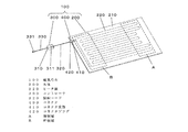
図1に示すように、本実施の形態における電気毛布100は、内部にヒータ線220を備え縦寸法が約190cm、横寸法が約130cmの略長方形の本体200と、本体200の通電を制御するコントローラ300と、本体200とコントローラ300を接続するコネクタ400とで構成されている。
As shown in FIG. 1, the
本実施の形態においては、本体の長手方向を上下方向とし、特に、通常の使用時において頭側となる方を上方、足側となる方を下方とする。また、本体の長辺を側方および左右方向として以下の説明を行う。 In the present embodiment, the longitudinal direction of the main body is the vertical direction, and in particular, the head side is the upper side and the foot side is the lower side during normal use. In addition, the following description will be made with the long side of the main body as the side and the left-right direction.
本体200は、アクリルとポリエステルからなる2枚の毛布210の積層体の外周部と中央部の要所を縫製糸で縫製することにより、縫製しない部分に形成されたトンネル状の挿通経路にヒータ線220を挿入して配置することにより、毛布210の略全面に亘りヒータ線220を蛇行させて配設されたものである。
The
図1に示すように、ヒータ線220は基本的には毛布210の上下方向に蛇行させて配設されている。本体200の上部では、両側部は毛布210の上端部の近傍までヒータ線220が配設されているのに対し、中央部は両側部より下方の範囲にのみヒータ線220が配設されている。このように、本体200の上部にはヒータ線220の配設密度が低い
疎領域Aが形成されている。疎領域Aは配設密度が低いため、加熱容量が小さく、低めの温度に維持される。
As shown in FIG. 1, the
これに対して、本体200の下部は全幅に亘って下端部の近傍までヒータ線220が配設されている。このように本体200の下部にはヒータ線220の配設密度が高い密領域Bが形成されている。密領域Bは配設密度が高いため、加熱容量が大きく、高めの温度に維持される。
On the other hand, the
上記のように本体の上下のヒータ線220の配設密度を変えることにより、使用者が就寝時に横たわった場合に、使用者の頭部側に加熱容量の小さい疎領域Aが配置され、足元側に加熱容量の大きい密領域Bが配置されることにより、頭寒足熱の快適な暖房効果をことができる。
By changing the arrangement density of the
図1に示すように、ヒータ線220の両端部は本体の下端縁の近傍に設置されたコネクタ受部410に接続されている。コネクタ受部410はコントローラ300の接続コード320の先端に接続されたコネクタプラグ420を着脱自在に接続できる構成となっている。本体200に設置されたコネクタ受部410とコントローラ300に設置されたコネクタプラグ420とでコネクタ400が構成されている。
As shown in FIG. 1, both end portions of the
図3に示すように、ヒータ線220は、ポリエステルなどの可撓性樹脂からなる芯線221の上に抵抗の大きい発熱線222が螺旋状に巻き付けられ、その外周にプラスチックサーミスタ層223が形成され、その外周に抵抗の小さい温度検知線224が螺旋状に巻き付けられ、その外周に塩化ビニールの絶縁層225で外被が形成されている。
As shown in FIG. 3, in the
プラスチックサーミスタ層223は塩化ビニールを主成分とし、温度によりインピーダンスが変化する樹脂である。プラスチックサーミスタ層223は内周面に配設された発熱線222と外周面に配設された温度検知線224に電気的に接続されており、発熱線222と温度検知線224によって温度検知信号を取り出すことができる。このように、ヒータ線220は、加熱機能と温度検出機能の2つの機能を備えている。
The
ヒータ線220の発熱線222の両端はコネクタ受部410と電気的に接続されており、コントローラ300から供給される電力により発熱する構成となっている。一方、温度検知線224は一端がコネクタ受部410と電気的に接続されており、温度検知情報をコントローラ300に送信できる構成となっている。
Both ends of the
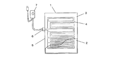
コントローラ300は、操作スイッチおよび制御機能を備えたコントローラ本体310と、コントローラ300と本体200を電気的に接続する接続コード320と、接続コード320の先端に設置されたコネクタプラグ420と、コントローラ本体310に電源を供給する電源コード330と、電源コード330の先端に設置された電源プラグ331で構成されている。コネクタプラグ420は本体200に設置されたコネクタ受部410とセットでコネクタ400を構成している。
The
コントローラ300の操作機能としては、電気毛布の電源を「入」、「切」する電源スイッチと電気毛布の温度を使用者の好みに合わせて設定する温度設定ダイヤルとを一体に構成したロータリ式のダイヤル311がコントローラ本体310の上面に設置されている。ダイヤル311は透明な樹脂材料で形成されており、その内部には通電状態を表示する電源ランプが配置されている。
As an operation function of the
<2>電気毛布の動作および作用
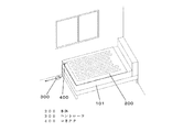
図3は電気毛布をベッドでの使用状態を示す斜視図である。
<2> Operation and Action of Electric Blanket FIG. 3 is a perspective view showing the usage state of the electric blanket in the bed.
電気毛布をベッド101で使用する場合は、本体200のコネクタ受部410が配置された側をベッド101の足元側に合わせて設置し、コントローラ300のコネクタプラグ420をコネクタ受部410に接続する。コントローラ300を床面に設置して使用することができ、また壁面等にぶら下げて使用してもよい。
When the electric blanket is used in the
また、このように設置することで必然的に本体200の疎領域がベッド101の頭側に、密領域Bがベッド101の足元側に配置され、頭寒足熱の快適な暖房効果を得ることができる。また、上下方向を間違って使用する誤使用を抑制することができる。
Moreover, by installing in this way, the sparse area | region of the
コントローラ300のダイヤル311を回転することにより電源スイッチが入り、電源ランプが点灯してヒータ線220に通電が開始される。ダイヤル311の回転角度を調節することにより温度を設定することができる。
When the
上記のように、本実施の形態の電気毛布は、図3に示すように、ベッド101が壁際に配置されている場合でも、コントローラ300は足元側に配置されることにより、一般的に寝具であるベッド101への出入りを行う電気毛布の側縁に、コントローラ本体310および接続コード320が配設されていないため、寝具への出入りの際に邪魔になることがなく、極めて使い勝手が良い。
As described above, the electric blanket according to the present embodiment is generally a bedding because the
また、このような使い勝手はベッドでの使用に限られるものではなく、布団で使用した場合においても、一般的に布団への出入りを行う電気毛布の側縁にコントローラ本体310および接続コード320が配設されていないため、同様な効果を得ることができるものである。
In addition, such usability is not limited to use in a bed, and even when used in a futon, the controller
また、電気毛布に疎領域と密領域を形成し、コネクタ受部410が密領域側の短辺近傍に配置することにより、上下方向を間違って使用することを抑制することができるため、頭寒足熱の快適な暖房効果を確実に得ることができ、誤使用を抑制することができ、安全性と使い勝手を向上することができる。
In addition, by forming a sparse region and a dense region in the electric blanket and disposing the
なお、本実施の形態においては、本体200のヒータ線220の配置において、上下方向に疎領域と密領域が形成されるように配置したが、これに限るものではなく、左右方向において中央部を密領域に両側部を疎領域に配置したもの、あるいは、全体を均等に配置したもの等が考えられるが、これらの配置を採用した場合でも、寝具への出入りに関する使い勝手については同様な効果を得ることができる。
In the present embodiment, the
以上のように、本発明にかかる電気毛布は、寝具への出入りの際の使い勝手を向上することができるので、寝具用の暖房機器等の用途にも適用できる。 As described above, since the electric blanket according to the present invention can improve the usability when entering and exiting the bedding, it can also be applied to uses such as heating equipment for bedding.
100 電気毛布
200 本体
220 ヒータ線
300 コントローラ
320 接続コード
400 コネクタ
410 コネクタ受部
420 コネクタプラグ
A 疎領域
B 密領域
DESCRIPTION OF
Claims (2)
前記ヒータ線の通電を制御するコントローラと、
前記本体と前記コントローラとを接続するコネクタと、を含み、
前記コネクタは、前記本体の短辺の縁部に設置されたコネクタ受部と、前記コントローラの接続コードの先端に設置されたコネクタプラグとが、着脱自在に接続可能な構成の、
電気毛布。 A substantially rectangular body arranged with meandering heater wires inside;
A controller for controlling energization of the heater wire;
A connector for connecting the main body and the controller;
The connector has a configuration in which a connector receiving portion installed at an edge of a short side of the main body and a connector plug installed at a tip of a connection cord of the controller can be detachably connected.
electric blanket.
前記コネクタ受部は、前記密領域が形成された短辺近傍の縁部に配置された、
請求項1に記載の電気毛布。 In the main body, a dense region with a high density of heater wires is formed in the vicinity of one short side, and a sparse region with a low density of heater wires is formed in the vicinity of the other short side,
The connector receiving portion is disposed at an edge near the short side where the dense region is formed,
The electric blanket according to claim 1.
Priority Applications (1)
| Application Number | Priority Date | Filing Date | Title |
|---|---|---|---|
| JP2015081386A JP2016201284A (en) | 2015-04-13 | 2015-04-13 | Electric heating blanket |
Applications Claiming Priority (1)
| Application Number | Priority Date | Filing Date | Title |
|---|---|---|---|
| JP2015081386A JP2016201284A (en) | 2015-04-13 | 2015-04-13 | Electric heating blanket |
Publications (1)
| Publication Number | Publication Date |
|---|---|
| JP2016201284A true JP2016201284A (en) | 2016-12-01 |
Family
ID=57424531
Family Applications (1)
| Application Number | Title | Priority Date | Filing Date |
|---|---|---|---|
| JP2015081386A Pending JP2016201284A (en) | 2015-04-13 | 2015-04-13 | Electric heating blanket |
Country Status (1)
| Country | Link |
|---|---|
| JP (1) | JP2016201284A (en) |
Citations (5)
| Publication number | Priority date | Publication date | Assignee | Title |
|---|---|---|---|---|
| JPS4728965Y1 (en) * | 1968-09-13 | 1972-08-31 | ||
| JPS4735072Y1 (en) * | 1968-12-26 | 1972-10-24 | ||
| JPS4856124U (en) * | 1971-10-29 | 1973-07-18 | ||
| JPS4863117U (en) * | 1971-11-19 | 1973-08-10 | ||
| JP2009259751A (en) * | 2008-04-11 | 2009-11-05 | Kiyohiro Mihara | Surface-heating body |
-
2015
- 2015-04-13 JP JP2015081386A patent/JP2016201284A/en active Pending
Patent Citations (5)
| Publication number | Priority date | Publication date | Assignee | Title |
|---|---|---|---|---|
| JPS4728965Y1 (en) * | 1968-09-13 | 1972-08-31 | ||
| JPS4735072Y1 (en) * | 1968-12-26 | 1972-10-24 | ||
| JPS4856124U (en) * | 1971-10-29 | 1973-07-18 | ||
| JPS4863117U (en) * | 1971-11-19 | 1973-08-10 | ||
| JP2009259751A (en) * | 2008-04-11 | 2009-11-05 | Kiyohiro Mihara | Surface-heating body |
Similar Documents
| Publication | Publication Date | Title |
|---|---|---|
| KR20120031847A (en) | Heating apparatus with local temperature control for bed | |
| ITMI20121058A1 (en) | IMPROVED THERMAL APPLIANCE AND METHOD OF USE | |
| KR20160099341A (en) | Heated Mat System | |
| JP4306293B2 (en) | Sheet electric heater | |
| JP2016201284A (en) | Electric heating blanket | |
| JP4757279B2 (en) | Electric therapy device for home use | |
| JP2017000311A (en) | Heating mat | |
| JP3746103B2 (en) | electric blanket | |
| JP6010761B2 (en) | Electric warmer | |
| KR101119312B1 (en) | Heating mattress include Charcoal and using direct current electric power | |
| JP5966153B2 (en) | Electric warmer | |
| JP6574977B2 (en) | Heating mat | |
| JP2022100484A (en) | Electric heating blanket | |
| CN206534443U (en) | Electric heating quilt with far infrared heating function | |
| US20090008376A1 (en) | Method and apparatus for a heated comforter | |
| CN204970583U (en) | Warm quilt of radiationless electricity of many gears control | |
| JP2013223624A (en) | Flat warmer | |
| CN205029887U (en) | Controlling means that generates heat that electric blanket was used | |
| JP5105300B2 (en) | Thermal pad | |
| RU217065U1 (en) | HEATING DEVICE | |
| JP2014114984A (en) | Electric warmer | |
| CN210986456U (en) | Electric heating pad | |
| KR102484123B1 (en) | Heating cushion and method for manufacture of Heating cushion | |
| KR20130022583A (en) | Manufacturing method of planar heating element and thermal mat using planar heating element manufactured thereby | |
| KR200477858Y1 (en) | Planar heating element is capable of sensing bodily sensation heating temperature |
Legal Events
| Date | Code | Title | Description |
|---|---|---|---|
| RD01 | Notification of change of attorney |
Free format text: JAPANESE INTERMEDIATE CODE: A7421 Effective date: 20160523 |
|
| A621 | Written request for application examination |
Free format text: JAPANESE INTERMEDIATE CODE: A621 Effective date: 20180328 |
|
| RD01 | Notification of change of attorney |
Free format text: JAPANESE INTERMEDIATE CODE: A7421 Effective date: 20190116 |
|
| A977 | Report on retrieval |
Free format text: JAPANESE INTERMEDIATE CODE: A971007 Effective date: 20190221 |
|
| A131 | Notification of reasons for refusal |
Free format text: JAPANESE INTERMEDIATE CODE: A131 Effective date: 20190226 |
|
| A02 | Decision of refusal |
Free format text: JAPANESE INTERMEDIATE CODE: A02 Effective date: 20190903 |