JP2016201211A - Temperature detection device and heating cooker - Google Patents

Temperature detection device and heating cooker Download PDF

Info

Publication number
JP2016201211A
JP2016201211A JP2015079337A JP2015079337A JP2016201211A JP 2016201211 A JP2016201211 A JP 2016201211A JP 2015079337 A JP2015079337 A JP 2015079337A JP 2015079337 A JP2015079337 A JP 2015079337A JP 2016201211 A JP2016201211 A JP 2016201211A
Authority
JP
Japan
Prior art keywords
temperature
heating
detection device
container
unit
Prior art date
Legal status (The legal status is an assumption and is not a legal conclusion. Google has not performed a legal analysis and makes no representation as to the accuracy of the status listed.)
Granted
Application number
JP2015079337A
Other languages
Japanese (ja)
Other versions
JP6425608B2 (en
Inventor
彰 森井
Akira Morii
彰 森井
吉野 勇人
Isato Yoshino
勇人 吉野
西 健一郎
Kenichiro Nishi
健一郎 西
椛島 山青
Sansei Kabashima
山青 椛島
Current Assignee (The listed assignees may be inaccurate. Google has not performed a legal analysis and makes no representation or warranty as to the accuracy of the list.)
Mitsubishi Electric Home Appliance Co Ltd
Mitsubishi Electric Corp
Original Assignee
Mitsubishi Electric Home Appliance Co Ltd
Mitsubishi Electric Corp
Priority date (The priority date is an assumption and is not a legal conclusion. Google has not performed a legal analysis and makes no representation as to the accuracy of the date listed.)
Filing date
Publication date
Application filed by Mitsubishi Electric Home Appliance Co Ltd, Mitsubishi Electric Corp filed Critical Mitsubishi Electric Home Appliance Co Ltd
Priority to JP2015079337A priority Critical patent/JP6425608B2/en
Publication of JP2016201211A publication Critical patent/JP2016201211A/en
Application granted granted Critical
Publication of JP6425608B2 publication Critical patent/JP6425608B2/en
Active legal-status Critical Current
Anticipated expiration legal-status Critical

Links

Images

Abstract

PROBLEM TO BE SOLVED: To provide a temperature detection device and a heating cooker that can accurately detect the temperature of various shapes of containers.SOLUTION: A temperature detection device 30 includes: a placement part 31 on which the bottom or curved portion of a container 10 containing an object to be heated is placed; a temperature sensor 34 which is placed on the placement part 31, and detects the temperature of the bottom or curved portion of the container 10; and a sensor side communication unit 332 which is connected with the placement part 31 and transmits temperature information detected by the temperature sensor 34.SELECTED DRAWING: Figure 4

Description

本発明は、被加熱物が収容される容器の温度を検知する温度検知装置および温度検知装置と連携動作を行う加熱調理器に関するものである。   The present invention relates to a temperature detection device that detects the temperature of a container in which an object to be heated is stored, and a cooking device that performs a cooperative operation with the temperature detection device.

従来の加熱調理器において、食材などが収容される鍋などの容器の温度を検知し、検知された温度に基づいて自動的に加熱制御を行うことが知られている。例えば、特許文献1に記載される加熱調理器では、トッププレート下面に赤外線センサを備え、鍋底面から放射される赤外線を検出して鍋底面温度を算出し、加熱制御を行う構成となっている。また、特許文献2および特許文献3には、鍋底の内部、または鍋の側面内部の高さ方向に温度センサを配置し、検知された温度情報を加熱調理器に送信して加熱制御を行う構成が記載されている。さらに、特許文献4には、鍋本体に取り付けられる鍋底部およびハンドルを備え、鍋底部に温度センサを配置し、当該温度センサによって検知された温度情報をハンドルに設けられた通信回路を介して送信する構成が記載されている。   In a conventional cooking device, it is known to detect the temperature of a container such as a pot in which ingredients are stored and to automatically perform heating control based on the detected temperature. For example, the heating cooker described in Patent Document 1 includes an infrared sensor on the lower surface of the top plate, detects infrared rays radiated from the bottom of the pan, calculates the pan bottom temperature, and performs heating control. . Moreover, in patent document 2 and patent document 3, a temperature sensor is arrange | positioned in the height direction of the inside of a pan bottom or the side surface of a pan, and the detected temperature information is transmitted to a heating cooker, and a heating control is performed. Is described. Further, Patent Document 4 includes a pan bottom portion and a handle attached to the pan body, and a temperature sensor is arranged on the pan bottom portion, and temperature information detected by the temperature sensor is transmitted via a communication circuit provided on the handle. The structure to be described is described.

特開2003−249341号公報(請求項1参照)JP 2003-249341 A (refer to claim 1) 特開2007−53038号公報(図1参照)JP 2007-53038 A (see FIG. 1) 特許第4936814号公報(図1参照)Japanese Patent No. 4936814 (see FIG. 1) 特表2012−514495号公報(図12参照)JP 2012-514495 A (see FIG. 12)

特許文献1に記載される構成の場合、鍋底から放射される赤外線の一部がトップレートによって遮蔽(吸収および反射)されること、および容器の底の材質および表面処理によって、赤外線の放射率が異なることなどの要因により、精確な温度を検知することは困難である。   In the case of the configuration described in Patent Document 1, a part of infrared rays emitted from the bottom of the pan is shielded (absorbed and reflected) by the top rate, and due to the material and surface treatment of the bottom of the container, the infrared emissivity is increased. It is difficult to detect an accurate temperature due to factors such as differences.

また、特許文献2および特許文献3に記載される構成の場合、トッププレートによる温度検知への影響がなくなるため、温度検知の追従性や精度向上が可能となる。しかしながら、内部に温度センサを備えた特定の鍋しか用いることができない。さらに、特許文献4に記載される構成の場合も、鍋底およびハンドルを取り付ける必要があるため、鍋の形状に制約があり、どんな形状の鍋にでも対応できるものではない。また、鍋またはハンドルに温度センサまたは通信回路などの部品を設けることにより、鍋の大型化および重量化を招き、使い勝手が悪くなってしまう。   Further, in the case of the configurations described in Patent Document 2 and Patent Document 3, since the influence on the temperature detection by the top plate is eliminated, the followability and accuracy of temperature detection can be improved. However, only specific pans with temperature sensors inside can be used. Furthermore, in the case of the configuration described in Patent Document 4, since it is necessary to attach a pan bottom and a handle, the shape of the pan is limited, and the pan cannot be adapted to any shape. In addition, by providing parts such as a temperature sensor or a communication circuit on the pan or the handle, the pan becomes large and heavy, and the usability is deteriorated.

本発明は、上記のような課題を背景になされたもので、様々な形状の容器の温度を高精度に検知することができる温度検知装置および加熱調理器を提供することを目的とする。   The present invention has been made in the background of the above problems, and an object thereof is to provide a temperature detection device and a heating cooker that can detect the temperature of containers of various shapes with high accuracy.

本発明に係る温度検知装置は、被加熱物が収容される容器の底部または湾曲部が載置される載置部に配置され、容器の底部または湾曲部の温度を検知する第1温度センサと、載置部に接続され、第1温度センサにより検知された温度情報を送信する第1通信部と、を備える。   A temperature detection device according to the present invention is disposed on a placing portion on which a bottom portion or a curved portion of a container in which an object to be heated is accommodated is placed, and detects a temperature of the bottom portion or the curved portion of the container; And a first communication unit that is connected to the mounting unit and transmits temperature information detected by the first temperature sensor.

本発明の温度検知装置によれば、載置部に様々な形状の容器を載置することができるとともに、載置部に配置された温度センサによって容器の温度を直接検知できる。また載置部に接続された通信部によって、温度センサによって検知された高精度の温度情報を送信することができる。   According to the temperature detection device of the present invention, containers of various shapes can be placed on the placement section, and the temperature of the container can be directly detected by the temperature sensor disposed on the placement section. Moreover, highly accurate temperature information detected by the temperature sensor can be transmitted by the communication unit connected to the placement unit.

実施の形態1における加熱調理器の斜視図である。3 is a perspective view of a heating cooker according to Embodiment 1. FIG. 実施の形態1における加熱調理器の主要部の構成と機能を説明する図である。It is a figure explaining the structure and function of the principal part of the heating cooker in Embodiment 1. FIG. 実施の形態1における加熱調理器の操作部および火力表示部を説明する図である。It is a figure explaining the operation part and thermal power display part of the heating cooker in Embodiment 1. FIG. (a)は実施の形態1における温度検知装置の平面図であり、(b)は側面図である。(A) is a top view of the temperature detection apparatus in Embodiment 1, (b) is a side view. 実施の形態1における温度検知装置の内部構成を説明する図である。FIG. 3 is a diagram illustrating an internal configuration of a temperature detection device in the first embodiment. トッププレートから容器底部までの距離と加熱効率との関係を示すグラフである。It is a graph which shows the relationship between the distance from a top plate to a container bottom part, and heating efficiency. (a)は温度検知装置の検知温度の推移の一例を示すグラフであり、(b)は加熱コイルに供給される電力の推移の一例を示すグラフである。(A) is a graph which shows an example of transition of the detection temperature of a temperature detection apparatus, (b) is a graph which shows an example of transition of the electric power supplied to a heating coil. 実施の形態1における温度差ΔT_proに基づく判定結果および当該判定結果に応じた動作の一例を示す表である。7 is a table showing an example of a determination result based on a temperature difference ΔT_pro in Embodiment 1 and an operation according to the determination result. 実施の形態1におけるセンサ判定処理の流れを示すフローチャートである。3 is a flowchart showing a flow of sensor determination processing in the first embodiment. 実施の形態2における温度検知装置の平面図である。6 is a plan view of a temperature detection device according to Embodiment 2. FIG. 実施の形態2における温度検知装置を用いた場合のセンサ判定処理の流れを示すフローチャートである。10 is a flowchart showing a flow of sensor determination processing when the temperature detection device in Embodiment 2 is used. 実施の形態3における温度検知装置の平面図である。6 is a plan view of a temperature detection device in Embodiment 3. FIG. (a)は実施の形態4における温度検知装置の平面図であり、(b)は側面図である。(A) is a top view of the temperature detection apparatus in Embodiment 4, (b) is a side view. 実施の形態5における温度検知装置30および加熱調理器の構成を説明する図である。It is a figure explaining the structure of the temperature detection apparatus 30 in Embodiment 5, and a heating cooker. 実施の形態6における温度検知装置30の構成を説明する図である。It is a figure explaining the structure of the temperature detection apparatus 30 in Embodiment 6. FIG. 実施の形態7における加熱調理器の主要部の構成と機能を説明する図である。It is a figure explaining the structure and function of the principal part of the heating cooker in Embodiment 7. FIG. (a)は、温度検知装置の検知温度の推移の一例を示すグラフであり、(b)は、赤外線温度センサの検知温度の推移の一例を示すグラフであり、(c)は、加熱コイルに供給される電力の推移の一例を示すグラフである。(A) is a graph which shows an example of transition of the detection temperature of a temperature detection apparatus, (b) is a graph which shows an example of transition of the detection temperature of an infrared temperature sensor, (c) is a heating coil. It is a graph which shows an example of transition of the electric power supplied. 実施の形態7における温度差ΔT_proおよび温度差ΔT_irに基づく判定結果および判定結果に応じた動作の一例を示す表である。20 is a table showing an example of a determination result based on a temperature difference ΔT_pro and a temperature difference ΔT_ir and an operation according to the determination result in the seventh embodiment. 実施の形態7におけるセンサ判定処理の流れを示すフローチャートである。18 is a flowchart showing a flow of sensor determination processing in the seventh embodiment. 実施の形態8における加熱調理器の斜視図である。It is a perspective view of the heating cooker in Embodiment 8. 実施の形態8における加熱調理器の操作表示部の表示例である。It is an example of a display of the operation display part of the heating cooker in Embodiment 8. 実施の形態8における加熱調理器の加熱動作を示すフローチャートである。It is a flowchart which shows the heating operation of the heating cooker in Embodiment 8. 変形例1におけるセンサ判定処理の流れを示すフローチャートである。It is a flowchart which shows the flow of the sensor determination process in the modification 1. 変形例2におけるセンサ判定処理の流れを示すフローチャートである。10 is a flowchart showing a flow of sensor determination processing in Modification 2.

以下、本発明における温度検知装置および加熱調理器の実施の形態について、図面を用いて説明する。なお、細かい構造および重複または類似する説明については、適宜簡略化または省略している。以下の実施の形態では、加熱調理器の一例として誘導加熱調理器について説明する。   Hereinafter, embodiments of a temperature detection device and a heating cooker according to the present invention will be described with reference to the drawings. Note that the detailed structure and overlapping or similar descriptions are appropriately simplified or omitted. In the following embodiments, an induction heating cooker will be described as an example of a heating cooker.

実施の形態1.
(加熱調理器の構成)
図1は、本発明の実施の形態1における加熱調理器100の斜視図である。加熱調理器100は、本体1と、本体1の上面に配置され、耐熱ガラスで形成されたトッププレート2とを有し、トッププレート2の上に載置される鍋やフライパン等の容器10を、本体1の内部に設けられた加熱部により加熱する。本実施の形態では、トッププレート2の左側手前、右側手前、および中央側奥の3箇所に、それぞれ加熱口6が設けられている。
Embodiment 1 FIG.
(Configuration of cooking device)
FIG. 1 is a perspective view of a heating cooker 100 according to Embodiment 1 of the present invention. The heating cooker 100 includes a main body 1 and a top plate 2 that is disposed on the upper surface of the main body 1 and is formed of heat-resistant glass, and a container 10 such as a pan or a frying pan placed on the top plate 2. Heating is performed by a heating unit provided inside the main body 1. In the present embodiment, heating ports 6 are respectively provided at three locations on the left side of the top plate 2, on the right side, and on the center side.

本体1の上面には、加熱条件や加熱指示の入力操作を受け付ける操作部3が、各加熱口6に対応して配置されている。また、本体1の前面には、例えばダイヤルスイッチによって構成され、加熱条件や加熱指示の入力操作を受け付ける前面操作部3aが配置されている。   On the upper surface of the main body 1, an operation unit 3 that receives an input operation of a heating condition or a heating instruction is arranged corresponding to each heating port 6. Further, on the front surface of the main body 1, a front operation unit 3 a configured by, for example, a dial switch and receiving an input operation of a heating condition or a heating instruction is disposed.

使用者が、被加熱物を収容した容器10をトッププレート2上に載置し、加熱口6に対応する操作部3または前面操作部3aを操作して加熱条件等の設定を行い、設定された内容に従って、容器10が加熱部により加熱される。加熱の進行状況や調理モードなどの設定に関する情報は、トッププレート2の上面に配置された液晶等を有する表示部4に表示され、加熱の火力は各加熱口に対応して配置された火力表示部5に表示される。   The user places the container 10 containing the object to be heated on the top plate 2 and operates the operation unit 3 or the front operation unit 3a corresponding to the heating port 6 to set the heating conditions and the like. According to the contents, the container 10 is heated by the heating unit. Information related to settings such as the progress of heating and cooking mode is displayed on the display unit 4 having a liquid crystal or the like disposed on the upper surface of the top plate 2, and the heating power is displayed corresponding to each heating port. Displayed in part 5.

トッププレート2の加熱口6に対応する部分には、容器10を載置する箇所を示す例えば円形の表示が印刷等によって設けられており、使用者は容器10を載置すべき場所がわかるようになっている。   The portion corresponding to the heating port 6 of the top plate 2 is provided with, for example, a circular display indicating a place where the container 10 is placed by printing or the like so that the user can know the place where the container 10 should be placed. It has become.

本体1内において加熱口6の下側には、加熱コイル14が設けられている。加熱コイル14が、本発明の「加熱部」に相当する。なお、図1では、加熱コイル14の配置を破線にて図示している。加熱コイル14に高周波電流を流すことでトッププレート2上に載置された容器10に渦電流が発生し、発生した渦電流と容器10との抵抗により容器10が発熱する。これにより、容器10を直接加熱する加熱効率の良い調理を実現できる。なお、加熱調理器100の加熱口6の加熱部として電気ヒータ等の他の加熱部を設けてもよい。   A heating coil 14 is provided below the heating port 6 in the main body 1. The heating coil 14 corresponds to the “heating unit” of the present invention. In addition, in FIG. 1, arrangement | positioning of the heating coil 14 is illustrated with the broken line. By supplying a high-frequency current to the heating coil 14, an eddy current is generated in the container 10 placed on the top plate 2, and the container 10 generates heat due to the resistance between the generated eddy current and the container 10. Thereby, cooking with good heating efficiency for directly heating the container 10 can be realized. In addition, you may provide other heating parts, such as an electric heater, as a heating part of the heating port 6 of the heating cooker 100. FIG.

図2は、本実施の形態における加熱調理器100の主要部の構成と機能とを説明する図である。なお、図2では、1つの加熱口6に対応する構成のみ図示しており、また、例えば水や食材等の被加熱物が収容された容器10と、容器10の温度を検知する温度検知装置30とを併せて図示している。温度検知装置30は、加熱調理器100とは別体に設けられ、容器10の底部の温度を検知し、検知した温度の情報を加熱調理器100へ送信するものである。温度検知装置30の詳細については後述する。   FIG. 2 is a diagram for explaining a configuration and functions of main parts of the heating cooker 100 according to the present embodiment. In FIG. 2, only the configuration corresponding to one heating port 6 is shown, and for example, a container 10 in which an object to be heated such as water or food is accommodated, and a temperature detection device that detects the temperature of the container 10. 30 together. The temperature detection device 30 is provided separately from the cooking device 100, detects the temperature of the bottom of the container 10, and transmits information on the detected temperature to the cooking device 100. Details of the temperature detection device 30 will be described later.

図2に示すように、トッププレート2に設けられた加熱口6の下部には、加熱コイル14が配置されている。本実施の形態では、加熱コイル14は、略環状の内側加熱コイル14aと、その外側に設けられた略環状の外側加熱コイル14bとを備えた二重環形状である。   As shown in FIG. 2, a heating coil 14 is disposed below the heating port 6 provided in the top plate 2. In the present embodiment, the heating coil 14 has a double ring shape including a substantially annular inner heating coil 14a and a substantially annular outer heating coil 14b provided outside thereof.

本体1の内部には、温度検知装置30と通信する機器側通信部21と、駆動部23を制御する機器側制御部22と、高周波インバータ24を駆動する駆動部23と、加熱コイル14に高周波電流を供給する高周波インバータ24と、が配置されている。機器側制御部22は、操作部3による設定内容と、温度検知装置30からの温度の情報に基づいて、駆動部23に対して高周波電力指令(火力情報)を送信する。機器側制御部22は、その機能を実現する回路デバイスなどのハードウェアを用いて構成されるか、またはマイコンやCPU等の演算装置と、その上で実行されるソフトウェアとで構成される。駆動部23は、機器側制御部22からの指令に基づき、高周波インバータ24を制御して加熱コイル14に流れる高周波電流を調整する。これにより、容器10の加熱制御が行われる。また、機器側制御部22は、温度検知装置30の状態を確認するための信号を生成し、その信号を、機器側通信部21を介して温度検知装置30へ送信する。   Inside the main body 1, a device-side communication unit 21 that communicates with the temperature detection device 30, a device-side control unit 22 that controls the drive unit 23, a drive unit 23 that drives the high-frequency inverter 24, and the heating coil 14 have high frequency. A high frequency inverter 24 for supplying current is disposed. The device-side control unit 22 transmits a high-frequency power command (thermal power information) to the drive unit 23 based on the setting content by the operation unit 3 and the temperature information from the temperature detection device 30. The device-side control unit 22 is configured by using hardware such as a circuit device that realizes the function, or is configured by an arithmetic device such as a microcomputer or a CPU and software executed thereon. The drive unit 23 adjusts the high-frequency current flowing through the heating coil 14 by controlling the high-frequency inverter 24 based on a command from the device-side control unit 22. Thereby, heating control of the container 10 is performed. In addition, the device-side control unit 22 generates a signal for confirming the state of the temperature detection device 30 and transmits the signal to the temperature detection device 30 via the device-side communication unit 21.

なお、機器側通信部21は、本発明における「第2通信部」に相当する。また、機器側制御部22は、本発明における「制御部」に相当する。   The device-side communication unit 21 corresponds to the “second communication unit” in the present invention. The device-side control unit 22 corresponds to a “control unit” in the present invention.

次に、加熱調理器100の操作部3および火力表示部5の構成について説明する。図3は、本実施の形態における加熱調理器100の操作部3および火力表示部5を説明する図である。加熱調理器100の左側、右側、および中央に設けられた加熱コイル14にそれぞれ対応する操作部3および火力表示部5は、すべて同様の構成であるので、ここでは、左側の加熱コイル14に対応して設けられた操作部3および火力表示部5を例に説明する。   Next, the configuration of the operation unit 3 and the thermal power display unit 5 of the cooking device 100 will be described. FIG. 3 is a diagram illustrating the operation unit 3 and the thermal power display unit 5 of the cooking device 100 according to the present embodiment. Since the operation unit 3 and the thermal power display unit 5 respectively corresponding to the heating coil 14 provided on the left side, the right side, and the center of the heating cooker 100 have the same configuration, here, they correspond to the left heating coil 14. The operation unit 3 and the thermal power display unit 5 provided as described above will be described as an example.

操作部3は、被加熱物を加熱する火力を設定するための火力設定キー3bと、調理メニューを設定するためのメニューキー3cとを備える。火力設定キー3bは、「弱火」キー、「中火」キー、「強火」キー、および「3kW」キーで構成されており、使用者は、これらのキーを用いて4段階の火力の何れかを設定することができるようになっている。火力に応じて個別にキーを設けることで、使用者は、必要な火力の設定を一回の操作で入力できるようになっている。   The operation unit 3 includes a heating power setting key 3b for setting a heating power for heating the object to be heated, and a menu key 3c for setting a cooking menu. The thermal power setting key 3b includes a “low fire” key, a “medium fire” key, a “high fire” key, and a “3 kW” key, and the user can use any of the four levels of thermal power using these keys. Can be set. By providing keys individually according to the thermal power, the user can input the necessary thermal power settings with a single operation.

メニューキー3cは、「揚げ物」キー、「予熱」キー、「煮込み」キー、および「タイマー」キーを備える。これらのキーが押下されると、各メニューに対して予め設定され記憶部(図示せず)に記憶された制御シーケンスに従って、機器側制御部22が加熱制御を行う。   The menu key 3 c includes a “fried food” key, a “preheat” key, a “boiled” key, and a “timer” key. When these keys are pressed, the device-side control unit 22 performs heating control according to a control sequence preset for each menu and stored in a storage unit (not shown).

火力表示部5は、火力設定キー3bで入力された火力や、メニューキー3cで設定されたメニューに基づいて火力を複数段階に表示するものであり、火力に応じて表示態様が切り替わる。火力表示部5の表示により、動作中であることを使用者に示すことが可能である。火力表示部5は、例えば複数のLEDを有し、これらLEDの点灯状態(点灯、消灯、点滅等)を切り替える、あるいは点灯色を切り替えることにより、火力を表現する。このようにすることで、使用者が直感的に分かりやすい報知を行うことができる。   The thermal power display unit 5 displays thermal power in a plurality of stages based on the thermal power input with the thermal power setting key 3b and the menu set with the menu key 3c, and the display mode is switched according to the thermal power. The display of the thermal power display unit 5 can indicate to the user that it is operating. The thermal power display unit 5 includes, for example, a plurality of LEDs, and expresses thermal power by switching the lighting states (lighting, extinguishing, blinking, etc.) of these LEDs or switching the lighting color. By doing in this way, the user can perform notification which is easy to understand intuitively.

なお、図3には図示しないが、液晶画面等で構成された表示部4(図1参照)には、例えば「予熱中」や「適温到達」等の火力や経過状況、設定されているメニューの内容等に関する情報が表示される。   Although not shown in FIG. 3, the display unit 4 (see FIG. 1) configured with a liquid crystal screen or the like has, for example, a thermal power and progress status such as “during preheating” and “appropriate temperature reached”, set menus, etc. Information on the contents of the is displayed.

(温度検知装置の構成)
次に、本実施の形態の温度検知装置30の構成について説明する。図4(a)は、温度検知装置30の平面図であり、図4(b)は、温度検知装置30の側面図である。また、図5は、温度検知装置30の内部構成を説明する図である。図4に示すように、温度検知装置30は、鍋敷きのような平面的な形状を有し、容器10が載置される載置部31と、機器側通信部21と通信する通信部33と、載置部31と通信部33とを接続する接続部32と、を備える。
(Configuration of temperature detector)
Next, the structure of the temperature detection apparatus 30 of this Embodiment is demonstrated. FIG. 4A is a plan view of the temperature detection device 30, and FIG. 4B is a side view of the temperature detection device 30. FIG. 5 is a diagram illustrating the internal configuration of the temperature detection device 30. As shown in FIG. 4, the temperature detection device 30 has a planar shape such as a pan, and a communication unit 33 that communicates with a placement unit 31 on which the container 10 is placed and a device-side communication unit 21. And a connection part 32 that connects the placement part 31 and the communication part 33.

載置部31は、使用時の平面視で中央に開口31aが形成された円環形状を有し、弾力性および耐熱性を有するシリコーンゴム等で構成される。載置部31の容器10が載置される面には、複数のドーム状の突起部311が形成される。複数の突起部311は、直径Dの円周上に等間隔で配置される。突起部311が配置される円の直径Dは、載置される容器10の最小径などから定められるものであり、例えば40mmである。複数の突起部311の内部にはそれぞれ温度センサ34が配置される。温度センサ34は、接触式の温度センサであり、載置部31に載置される容器10の底部の温度を検知する。温度センサ34は、例えばサーミスタまたは熱電対により構成される。   The mounting portion 31 has an annular shape with an opening 31a formed in the center in a plan view when used, and is made of silicone rubber or the like having elasticity and heat resistance. A plurality of dome-shaped protrusions 311 are formed on the surface of the placement portion 31 on which the container 10 is placed. The plurality of protrusions 311 are arranged at equal intervals on the circumference of the diameter D. The diameter D of the circle on which the protrusion 311 is arranged is determined from the minimum diameter of the container 10 to be placed, and is 40 mm, for example. A temperature sensor 34 is disposed inside each of the plurality of protrusions 311. The temperature sensor 34 is a contact-type temperature sensor and detects the temperature of the bottom of the container 10 placed on the placement unit 31. The temperature sensor 34 is configured by, for example, a thermistor or a thermocouple.

容器10が載置部31に載置されると、容器10の底部が突起部311と接触する。突起部311を、弾力性を有するシリコーンゴム等で形成することで、容器10の底部と突起部311とが密着し、接触面積が増加する。また、容器10の底部に密着する突起部311内に温度センサ34を設けることで、温度センサ34が容器10の底部に接触し、容器10の温度を高精度で検知することができる。   When the container 10 is placed on the placement unit 31, the bottom of the container 10 comes into contact with the protrusion 311. By forming the protrusion 311 with elastic silicone rubber or the like, the bottom of the container 10 and the protrusion 311 are in close contact with each other, and the contact area increases. Further, by providing the temperature sensor 34 in the protrusion 311 that is in close contact with the bottom of the container 10, the temperature sensor 34 comes into contact with the bottom of the container 10, and the temperature of the container 10 can be detected with high accuracy.

なお、図4の例では、3つの突起部311が形成され、各突起部311に温度センサ34が配置される構成となっているが、これに限定されるものではない。例えば、3つの突起部311の何れか1つに温度センサ34を備える構成としてもよく、または2つ以下もしくは4つ以上の突起部311に1つ以上の温度センサ34を備える構成としても良い。ただし、突起部311の数を3つ以上とすることで、容器10を安定して支持することができる。また、温度センサ34を複数設けることで、断線等が生じた場合にも温度検知を継続することができる。   In the example of FIG. 4, three protrusions 311 are formed, and the temperature sensor 34 is arranged in each protrusion 311. However, the present invention is not limited to this. For example, the temperature sensor 34 may be provided in any one of the three protrusions 311, or one or more temperature sensors 34 may be provided in two or less or four or more protrusions 311. However, the container 10 can be stably supported by setting the number of the protrusions 311 to three or more. Also, by providing a plurality of temperature sensors 34, temperature detection can be continued even when a disconnection or the like occurs.

また、図4(b)に示す載置部31の厚みtは、突起部311を含む最大厚みで5mm未満とする。載置部31の厚みtを5mmとした場合、温度検知装置30に載置される容器10は、加熱調理器100のトッププレート2から約5mm離れることになる。ここで、容器10が加熱コイル14から離れると、磁束は距離の二乗に反比例して減衰する。そのため、一般的に容器10を加熱コイル14から離すことにより、加熱効率も低下すると考えられる。しかしながら、実際には、トッププレート2と容器10とが接触している場合、容器10の熱の一部がトッププレート2に逃げてしまう。   Moreover, the thickness t of the mounting portion 31 shown in FIG. 4B is less than 5 mm in terms of the maximum thickness including the protruding portion 311. When the thickness t of the placing portion 31 is 5 mm, the container 10 placed on the temperature detection device 30 is separated from the top plate 2 of the heating cooker 100 by about 5 mm. Here, when the container 10 moves away from the heating coil 14, the magnetic flux attenuates in inverse proportion to the square of the distance. Therefore, it is generally considered that the heating efficiency is lowered by separating the container 10 from the heating coil 14. However, actually, when the top plate 2 and the container 10 are in contact, a part of the heat of the container 10 escapes to the top plate 2.

図6は、トッププレート2から容器10の底部までの距離と加熱効率との関係を示すグラフである。図6では、トッププレート2と容器10との間に絶縁物を配置し、トッププレート2と容器10との間に空気層を形成する。そして、絶縁物の大きさを変えてトッププレート2から容器10までの距離を変更し、各距離における湯沸しの加熱効率を測定した実験より得られた結果である。図6に示すように、トッププレート2から容器10までの距離が0mmの場合よりも、トッププレート2から容器10までの距離が約2mmの場合の方が、加熱効率が約2%高くなる。ここで、トッププレート2に一般的に用いられるネオセラムガラスの熱伝導率Kは、1.6であり、空気の熱伝導率Kは0.0241である。そのため、容器10とトッププレート2が接触している場合よりも、空気層が形成される場合の方が、熱伝導が少なくなり、加熱効率が良くなる。   FIG. 6 is a graph showing the relationship between the distance from the top plate 2 to the bottom of the container 10 and the heating efficiency. In FIG. 6, an insulator is disposed between the top plate 2 and the container 10, and an air layer is formed between the top plate 2 and the container 10. And it is the result obtained from the experiment which changed the distance from the top plate 2 to the container 10 by changing the magnitude | size of an insulator, and measured the heating efficiency of the boiling water in each distance. As shown in FIG. 6, the heating efficiency is about 2% higher when the distance from the top plate 2 to the container 10 is about 2 mm than when the distance from the top plate 2 to the container 10 is 0 mm. Here, the thermal conductivity K of neo-serum glass generally used for the top plate 2 is 1.6, and the thermal conductivity K of air is 0.0241. Therefore, the heat conduction is reduced and the heating efficiency is improved when the air layer is formed, compared with the case where the container 10 and the top plate 2 are in contact with each other.

ただし、図6に示すように、トッププレート2から容器10までの距離が5mm以上になると、トッププレート2から容器10までの距離が0mmの場合よりも、加熱効率が低下する。そのため、トッププレート2から容器10までの距離を5mm未満とすることで、トッププレート2と容器10との間の隙間量が0mmの場合の加熱効率と略同等もしくはそれ以上の加熱効率を実現することができる。なお、載置部31に用いられるシリコーンゴムの熱伝導率Kは、0.2であり、空気の熱伝導率よりは高いものの、突起部311上に容器10を載置することで、容器10との接触面積が限定され、熱伝導が抑制される。   However, as shown in FIG. 6, when the distance from the top plate 2 to the container 10 is 5 mm or more, the heating efficiency is lower than when the distance from the top plate 2 to the container 10 is 0 mm. Therefore, by making the distance from the top plate 2 to the container 10 less than 5 mm, a heating efficiency substantially equal to or higher than the heating efficiency when the gap amount between the top plate 2 and the container 10 is 0 mm is realized. be able to. In addition, although the thermal conductivity K of the silicone rubber used for the mounting part 31 is 0.2, which is higher than the thermal conductivity of air, the container 10 is placed on the protruding part 311 by placing the container 10 thereon. The contact area is limited, and heat conduction is suppressed.

また、突起部311の高さは、容器10の底部の反りを考慮して、1mmとする。詳しくは、容器10として用いられる鍋またはフライパンの中には、加熱による変形を考慮して、底部を予め上側(凸状)に反らせているものがある。例えば、容器10の底部の中心における反りの最大値が3mmであると想定した場合、容器10の径方向の外側に向かって次第に反りが小さくなり、突起部311が配置される直径40mmの位置(すなわち中心から半径20mmの位置)では、1mm程度の反りとなる。そのため、突起部311を1mm以上とすることで、容器10の底部が予め反っている場合でも、突起部311を確実に容器10の底部に接触させることができる。   The height of the protrusion 311 is set to 1 mm in consideration of the warp of the bottom of the container 10. Specifically, some pans or frying pans used as the container 10 have the bottom bent upward (convex shape) in advance in consideration of deformation due to heating. For example, when it is assumed that the maximum value of warpage at the center of the bottom of the container 10 is 3 mm, the warpage gradually decreases toward the outside in the radial direction of the container 10, and the position of the diameter 40 mm where the protrusion 311 is disposed ( That is, at a radius of 20 mm from the center, the warp is about 1 mm. Therefore, by setting the protrusion 311 to be 1 mm or more, the protrusion 311 can be reliably brought into contact with the bottom of the container 10 even when the bottom of the container 10 is warped in advance.

図4および図5に戻って、複数の温度センサ34は、それぞれ接続部32を介して通信部33に配線接続され、検知結果を通信部33へ出力する。また、通信部33は、載置部31に載置される容器10と接触しないように、使用時の平面視で載置部31の外側に配置される。より詳しくは、温度検知装置30が加熱口6上に配置された状態において、通信部33が加熱コイル14よりも外側に配置されるように、接続部32の長さが定められる。   Returning to FIG. 4 and FIG. 5, the plurality of temperature sensors 34 are connected to the communication unit 33 via the connection unit 32 and output the detection result to the communication unit 33. Moreover, the communication part 33 is arrange | positioned on the outer side of the mounting part 31 by planar view at the time of use so that the container 10 mounted in the mounting part 31 may not be contacted. More specifically, the length of the connection portion 32 is determined so that the communication portion 33 is disposed outside the heating coil 14 in a state where the temperature detection device 30 is disposed on the heating port 6.

通信部33は、センサ側通信部331、センサ側制御部332および電源部333を備えている。上記各部は、円筒形状の筐体330内に収容され、水密状態で封止されている。筐体330は、耐熱性および耐衝撃性を有し、かつ電波を遮蔽しない構造を有する。詳しくは、筐体330の上面330aは、耐衝撃性および防磁効果を有する材料(例えばアルミなど)で形成される。また、本体330bは、電波を遮蔽せず、耐熱性および摩擦係数が高い材料(例えばPPS、PC、シリコーンゴム、セラミックスなど)で形成され、表面をシリコーンゴムで皮膜される。なお、本体330bの少なくとも一部に金属以外の電波を透過する材料を用いてもよい。また、筐体330には、図示しない電源スイッチが設けられる。この電源スイッチが操作されることにより、温度検知装置30がオン状態とされる。   The communication unit 33 includes a sensor side communication unit 331, a sensor side control unit 332, and a power supply unit 333. Each of the above parts is housed in a cylindrical housing 330 and sealed in a watertight state. The housing 330 has heat resistance and impact resistance and has a structure that does not shield radio waves. Specifically, the upper surface 330a of the housing 330 is formed of a material (for example, aluminum) having impact resistance and a magnetic shielding effect. The main body 330b is formed of a material that does not shield radio waves, has high heat resistance and high friction coefficient (for example, PPS, PC, silicone rubber, ceramics, etc.), and has a surface coated with silicone rubber. Note that a material that transmits radio waves other than metal may be used for at least a part of the main body 330b. The housing 330 is provided with a power switch (not shown). By operating this power switch, the temperature detection device 30 is turned on.

センサ側通信部331は、センサ側制御部332による制御の下、加熱調理器100の本体1に配置された機器側通信部21と、双方向の情報通信を行う。センサ側通信部331と機器側通信部21との情報通信は、例えば、2.4GHz帯域の無線通信モジュールを用いて行われる。無線モジュールを用いる事で、温度検知装置30の外部にコネクタ部分を設ける必要がなくなり、温度検知装置30内部への浸水により回路がショートすることを軽減することができる。また、配線レスとなり容器10の取っ手等に配線が引っかかることを防止でき、例えば奥側の加熱口6で使いやすくなり、使い勝手も向上する。また、宅内に設けた2.4GHzのWi−Fi(IEEE802.11規格)モジュールへと情報伝送する事が可能となり、外部無線通信機器との拡張性を有する。   The sensor side communication unit 331 performs bidirectional information communication with the device side communication unit 21 arranged in the main body 1 of the heating cooker 100 under the control of the sensor side control unit 332. Information communication between the sensor-side communication unit 331 and the device-side communication unit 21 is performed using, for example, a 2.4 GHz band wireless communication module. By using the wireless module, it is not necessary to provide a connector part outside the temperature detection device 30, and it is possible to reduce a short circuit due to water immersion inside the temperature detection device 30. In addition, since the wiring is not required, it is possible to prevent the wiring from being caught on the handle of the container 10 and the like, for example, the heating port 6 on the back side is easy to use, and the usability is improved. In addition, information can be transmitted to a 2.4 GHz Wi-Fi (IEEE802.11 standard) module provided in the home, and has expandability with external wireless communication devices.

なお、周波数帯に関しては、2.4GHz帯に限らず900MHz帯や300〜500MHz帯以下の周波数帯の通信周波数帯を用いた特定小電力無線局通信モジュールを使用してもよい。例えば、誘導加熱調理器(IHクッキングヒータ)における誘導電流の周波数は20〜30kHz帯の周波数帯を用いており、電子レンジにおける電磁波の周波数は2.45GHz帯の周波数帯を用いている。このため、900MHzや300〜500MHz帯の周波数であれば、他の調理機器との干渉を起こすことなく通信を行う事が可能となる。   In addition, regarding a frequency band, you may use the specific low-power radio station communication module using not only a 2.4 GHz band but the 900 MHz band and the frequency band below 300-500 MHz band. For example, the frequency of the induction current in the induction heating cooker (IH cooking heater) uses a frequency band of 20 to 30 kHz, and the frequency of the electromagnetic wave in the microwave oven uses a frequency band of 2.45 GHz. For this reason, if it is a frequency of 900 MHz or 300-500 MHz band, it will become possible to communicate, without causing interference with other cooking appliances.

さらに、上記以外にもBluetooth(登録商標)またはRFID(Radio Frequency Identifier)などを用いて情報通信を行ってもよい。ただし、RFIDを用いる場合は、センサ側通信部331と機器側通信部21とを位置決めする必要があるため、トッププレート2の上面に通信部33の配置位置を示す表示を行う。また、センサ側通信部331と機器側通信部21との情報通信は無線通信に限定されるものではなく、ケーブルを用いた有線通信であってもよい。   In addition to the above, information communication may be performed using Bluetooth (registered trademark) or RFID (Radio Frequency Identifier). However, when the RFID is used, the sensor-side communication unit 331 and the device-side communication unit 21 need to be positioned, and thus a display indicating the arrangement position of the communication unit 33 is performed on the upper surface of the top plate 2. The information communication between the sensor side communication unit 331 and the device side communication unit 21 is not limited to wireless communication, and may be wired communication using a cable.

センサ側制御部332は、温度検知装置30の各構成部を制御する。センサ側制御部332は、その機能を実現する回路デバイスなどのハードウェアを用いて構成されるか、またはマイコンやCPU等の演算装置と、その上で実行されるソフトウェアとで構成される。センサ側制御部332は、温度センサ34によって検知された温度情報を、センサ側通信部331を介して機器側通信部21へ送信する。ここでは、複数の温度センサ34によって検知された温度のうち、最も高い温度が、温度情報として送信される。なお、別の実施の形態では、複数の温度センサ34によって検知された温度の平均値を温度情報として送信してもよい。また、センサ側制御部332は、機器側制御部22から状態確認の信号を受信した場合、センサ側通信部331を介して、機器側制御部22へ電源がオン状態であることを示す信号を送信する。電源部333は、各構成部に電力を供給するための電池である。   The sensor side control unit 332 controls each component of the temperature detection device 30. The sensor-side control unit 332 is configured by using hardware such as a circuit device that realizes the function, or is configured by an arithmetic device such as a microcomputer or a CPU and software executed thereon. The sensor side control unit 332 transmits the temperature information detected by the temperature sensor 34 to the device side communication unit 21 via the sensor side communication unit 331. Here, the highest temperature among the temperatures detected by the plurality of temperature sensors 34 is transmitted as temperature information. In another embodiment, an average value of temperatures detected by a plurality of temperature sensors 34 may be transmitted as temperature information. In addition, when the sensor-side control unit 332 receives a state confirmation signal from the device-side control unit 22, the sensor-side control unit 332 sends a signal indicating that the power supply is on to the device-side control unit 22 via the sensor-side communication unit 331. Send. The power supply unit 333 is a battery for supplying power to each component unit.

なお、センサ側通信部331は、本発明における「第1通信部」に相当する。また、温度センサ34は、本発明における「第1温度センサ」に相当する。   The sensor side communication unit 331 corresponds to the “first communication unit” in the present invention. The temperature sensor 34 corresponds to a “first temperature sensor” in the present invention.

(加熱調理動作)
次に、本実施の形態における加熱調理器100の加熱動作を説明する。加熱調理器100の機器側制御部22は、目標温度が設定された自動調理モードを有している。自動調理モードでは、温度検知装置30から取得した温度が目標温度となるように加熱コイル14の加熱制御が行われる。自動調理モードとしては、例えば、湯沸しモード、揚げ物調理モード、煮込み調理モード、麺ゆでモード、温泉卵モード、および温度一定制御モードがある。各モードは、それぞれ、目標温度および加熱時間の少なくとも一方が他のモードと異なる。なお、機器側制御部22は、これらのモードのうちの少なくとも1つのモードを実行する構成であればよい。
(Cooking operation)
Next, the heating operation of the heating cooker 100 in the present embodiment will be described. The apparatus side control unit 22 of the heating cooker 100 has an automatic cooking mode in which a target temperature is set. In the automatic cooking mode, the heating control of the heating coil 14 is performed so that the temperature acquired from the temperature detection device 30 becomes the target temperature. Examples of the automatic cooking mode include a water boiling mode, a fried food cooking mode, a stew cooking mode, a noodle boiled mode, a hot spring egg mode, and a constant temperature control mode. Each mode is different from the other modes in at least one of the target temperature and the heating time. The device-side control unit 22 may be configured to execute at least one of these modes.

自動調理モードにおいて、温度検知装置30と加熱調理器100とを連動させて加熱制御を行う場合、温度検知装置30が加熱される加熱口6上に配置されていないと、加熱される容器10の温度を検知できず、誤った加熱制御が行われてしまう。そこで、本実施の形態の機器側制御部22は、自動調理モードを実行する前に、加熱対象の加熱口6上に温度検知装置30が配置されているか否かを判定するセンサ判定処理を行う。   In the automatic cooking mode, when the temperature detection device 30 and the heating cooker 100 are linked to perform heating control, if the temperature detection device 30 is not disposed on the heating port 6 to be heated, the container 10 to be heated The temperature cannot be detected, and incorrect heating control is performed. Therefore, the device-side control unit 22 of the present embodiment performs a sensor determination process for determining whether or not the temperature detection device 30 is disposed on the heating port 6 to be heated before executing the automatic cooking mode. .

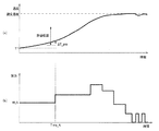
図7(a)は、温度検知装置30の検知温度の推移の一例を示すグラフであり、図7(b)は加熱コイル14に供給される電力の推移の一例を示すグラフである。ここで、加熱されている加熱口6の上に温度検知装置30が配置されている場合、温度検知装置30によって検知される温度は、図7(a)に示すように時間の経過とともに上昇する。そして、所定の時間(Time_A)経過後の温度差(ΔT_pro)が所定の許容範囲内に入っている場合、加熱されている加熱口6の上に温度検知装置30が配置されていると判定される。   FIG. 7A is a graph showing an example of the transition of the detected temperature of the temperature detection device 30, and FIG. 7B is a graph showing an example of the transition of the power supplied to the heating coil 14. Here, when the temperature detection device 30 is disposed on the heating port 6 being heated, the temperature detected by the temperature detection device 30 increases with time as shown in FIG. . When the temperature difference (ΔT_pro) after the lapse of a predetermined time (Time_A) is within a predetermined allowable range, it is determined that the temperature detection device 30 is disposed on the heated heating port 6. The

図8は、温度差ΔT_proに基づく判定結果および当該判定結果に応じた動作の一例を示す表である。図8に示すように、温度差ΔT_proが15℃以下の場合、すなわち、所定時間経過後の温度変化が許容範囲よりも小さい場合、加熱されている加熱口6の上に温度検知装置30が配置されていないと判定される。一方、温度差ΔT_proが30℃より大きい場合、すなわち、所定時間経過後の温度変化が許容範囲よりも大きい場合、加熱されている加熱口6の上に温度検知装置30が配置されているものの、容器10内に被加熱物はなく、空焼き状態であると判定される。そのため、温度差ΔT_proが、所定の範囲内でない場合には、加熱を停止し、図8に示す判定結果を報知する。   FIG. 8 is a table showing an example of a determination result based on the temperature difference ΔT_pro and an operation according to the determination result. As shown in FIG. 8, when the temperature difference ΔT_pro is 15 ° C. or less, that is, when the temperature change after a predetermined time has passed is smaller than the allowable range, the temperature detection device 30 is disposed on the heated heating port 6. It is determined that it has not been done. On the other hand, when the temperature difference ΔT_pro is larger than 30 ° C., that is, when the temperature change after a predetermined time has passed is larger than the allowable range, the temperature detection device 30 is disposed on the heated heating port 6. There is no object to be heated in the container 10, and it is determined that the container 10 is in an baked state. Therefore, when the temperature difference ΔT_pro is not within the predetermined range, the heating is stopped and the determination result shown in FIG. 8 is notified.

図9は、本実施の形態におけるセンサ判定処理の流れを示すフローチャートである。本処理は、加熱調理器100の電源がオンされた場合に、機器側制御部22によって開始される。本処理では、まず、自動調理モードが選択されたか否かが判断される(S1)。自動調理モードは、加熱対象となる加熱口6に対応する操作部3の自動調理モードが押下されることで選択される。ここで、自動調理モードが選択されていない場合は(S1:NO)、本処理を終了する。自動調理モードが選択されていない場合は、操作部3の操作に従った加熱制御が行われる。   FIG. 9 is a flowchart showing the flow of sensor determination processing in the present embodiment. This process is started by the device-side control unit 22 when the power of the cooking device 100 is turned on. In this process, it is first determined whether or not the automatic cooking mode has been selected (S1). The automatic cooking mode is selected by pressing the automatic cooking mode of the operation unit 3 corresponding to the heating port 6 to be heated. Here, when the automatic cooking mode is not selected (S1: NO), this process ends. When the automatic cooking mode is not selected, heating control according to the operation of the operation unit 3 is performed.

一方、自動調理モードが選択された場合(S1:YES)、機器側通信部21から温度検知装置30へ状態確認の信号が送信される(S2)。温度検知装置30の電源がオン状態である場合には、センサ側通信部331によって状態確認の信号が受信され、センサ側制御部332は、センサ側通信部331を介して、電源がオン状態であることを示す信号を返信する。   On the other hand, when the automatic cooking mode is selected (S1: YES), a state confirmation signal is transmitted from the device-side communication unit 21 to the temperature detection device 30 (S2). When the power supply of the temperature detection device 30 is in the on state, the sensor side communication unit 331 receives a state confirmation signal, and the sensor side control unit 332 is in the on state through the sensor side communication unit 331. A signal indicating that there is a response is returned.

そして、機器側制御部22によって、温度検知装置30から、電源がオン状態であることを示す信号の返信があったか否かが判断される(S3)。ここで、温度検知装置30から電源がオン状態であることを示す信号の返信が無い場合(S3:NO)、機器側制御部22は、温度検知装置30が通信不良、または電源がオンされていないと判断し、加熱調理器100に設けた表示部4等により、自動調理モードの動作が不可である旨の報知を行う(S4)。なお、この報知は表示部4による表示に限らず、例えばブザーや音声などで報知してもよく、報知内容は温度検知装置30の電源が入っていない、または通信エラーが発生していることを報知するものであってもよい。   And it is judged by the apparatus side control part 22 whether the signal which shows that the power supply is an ON state was received from the temperature detection apparatus 30 (S3). Here, when there is no response from the temperature detection device 30 indicating that the power supply is on (S3: NO), the device-side control unit 22 indicates that the temperature detection device 30 has a poor communication or the power supply is turned on. It judges that there is not, and notifies that operation of automatic cooking mode is impossible by display part 4 etc. which were provided in cooking-by-heating machine 100 (S4). This notification is not limited to the display by the display unit 4, and may be notified by, for example, a buzzer or voice. The notification content indicates that the temperature detection device 30 is not turned on or a communication error has occurred. You may notify.

機器側制御部22は、報知後、再度、温度検知装置30へ状態確認の信号を送付し、返信が得られず、3回繰り返した場合(S5:YES)、自動調理モードを実行することなく、本処理を終了する。このように、加熱制御を開始するよりも先に温度検知装置30の状態確認を行う事で、鍋や食材が加熱される前に使用者に温度検知装置30が正常使用の状態にないことを伝える事ができる。   After the notification, the device-side control unit 22 sends a state confirmation signal to the temperature detection device 30 again, and when a reply is not obtained and is repeated three times (S5: YES), the automatic cooking mode is not executed. This process is terminated. Thus, by checking the state of the temperature detection device 30 before starting the heating control, the temperature detection device 30 is not in a normal use state before the pan or food is heated. I can tell you.

一方、温度検知装置30から、電源がオン状態であることを示す信号の返信があった場合(S3:YES)、初期温度として、温度検知装置30による検知温度T_pro1が取得される(S6)。そして、所定の電力量(W_A)で、加熱コイル14による加熱が開始される(S7)。その後、所定時間が経過したか否かが判断され(S8)、所定時間が経過していない場合は(S8:NO)、所定の電力量(W_A)での加熱が継続される。一方、所定時間が経過した場合は(S8:YES)、温度検知装置30による所定時間経過後の検知温度T_pro2が取得される(S9)。なお、検知温度T_pro1は本発明の「第1温度」に相当し、検知温度T_pro2は本発明の「第2温度」に相当する。   On the other hand, when a signal indicating that the power is on is returned from the temperature detection device 30 (S3: YES), the temperature T_pro1 detected by the temperature detection device 30 is acquired as the initial temperature (S6). Then, heating by the heating coil 14 is started with a predetermined amount of power (W_A) (S7). Thereafter, it is determined whether or not a predetermined time has elapsed (S8). If the predetermined time has not elapsed (S8: NO), heating with a predetermined electric energy (W_A) is continued. On the other hand, when the predetermined time has elapsed (S8: YES), the temperature T_pro2 detected by the temperature detection device 30 after the predetermined time has elapsed is acquired (S9). The detected temperature T_pro1 corresponds to the “first temperature” of the present invention, and the detected temperature T_pro2 corresponds to the “second temperature” of the present invention.

そして、温度T_pro2と温度T_pro1との差ΔT_proが、所定範囲内であるか否かが判断される(S10)。所定範囲は、例えば図9に示す許容範囲である。そして、温度T_pro22と温度T_pro21との差ΔT_proが、所定範囲内である場合(S10:YES)、自動調理モードによる加熱制御が実行される(S11)。自動調理モードによる加熱制御において、温度検知装置30のセンサ側制御部332は、例えば1秒周期にて、温度センサ34によって検知した温度情報を、センサ側通信部331に送信させる。本体1の機器側通信部21は、温度検知装置30からの温度情報を受信し、機器側制御部22は、機器側通信部21が受信した温度情報を取得する。機器側制御部22は、予め設定されている目標温度に向けて高周波インバータ24を制御し、温度情報が目標温度になるよう、加熱の停止と開始とを繰り返す。   Then, it is determined whether or not the difference ΔT_pro between the temperature T_pro2 and the temperature T_pro1 is within a predetermined range (S10). The predetermined range is an allowable range shown in FIG. 9, for example. When the difference ΔT_pro between the temperature T_pro22 and the temperature T_pro21 is within the predetermined range (S10: YES), the heating control in the automatic cooking mode is executed (S11). In the heating control in the automatic cooking mode, the sensor side control unit 332 of the temperature detection device 30 causes the sensor side communication unit 331 to transmit the temperature information detected by the temperature sensor 34, for example, at a cycle of 1 second. The device side communication unit 21 of the main body 1 receives the temperature information from the temperature detection device 30, and the device side control unit 22 acquires the temperature information received by the device side communication unit 21. The device-side control unit 22 controls the high-frequency inverter 24 toward a preset target temperature, and repeats the stop and start of heating so that the temperature information becomes the target temperature.

一方、温度T_pro22と温度T_pro21との差ΔT_proが、所定範囲内でない場合には(S10:NO)、加熱が停止され(S12)、表示部4を用いて図8に示す判定結果が報知される(S13)。なお、表示部4は、本発明の「報知部」に相当する。   On the other hand, when the difference ΔT_pro between the temperature T_pro22 and the temperature T_pro21 is not within the predetermined range (S10: NO), the heating is stopped (S12), and the determination result shown in FIG. (S13). The display unit 4 corresponds to the “notification unit” of the present invention.

以上のように、本実施の形態では、温度検知装置30によって容器10の温度を直接検知することで、検知精度および検知の追従性の向上を図ることができる。その結果、自動調理モードにおける高精度な温度制御が可能となり、温度の上げ過ぎによる調理の失敗を抑制でき、使用者が火力変更動作をすることなく食材に適した調理が可能となる。よって、利便性の向上や吹き零れや空焼きなどによる温度上昇を抑える事が可能となり、無駄な加熱を抑えることができる。   As described above, in the present embodiment, the temperature detection device 30 directly detects the temperature of the container 10, thereby improving detection accuracy and detection follow-up. As a result, highly accurate temperature control in the automatic cooking mode is possible, cooking failure due to excessive temperature rise can be suppressed, and cooking suitable for foods can be performed without the user performing a heating power changing operation. Therefore, it is possible to improve convenience, to suppress the temperature rise due to spilling or emptying, and to suppress unnecessary heating.

また、載置部31と通信部33とが一体型に形成された温度検知装置30を用いることで、容器10に温度センサおよび通信部を設ける必要がなく、どのような形状の鍋にも用いることができる。さらに、機器側制御部22にてセンサ判定処理を行うことで、加熱口6に温度検知装置30が配置されていない場合の誤った加熱制御を防ぐことができる。また、温度検知装置30を容器10とトッププレート2との間に設けることで、トッププレート2の焦げ付きも抑制される。   Moreover, it is not necessary to provide a temperature sensor and a communication part in the container 10 by using the temperature detection apparatus 30 in which the placing part 31 and the communication part 33 are integrally formed. be able to. Furthermore, by performing the sensor determination process in the device-side control unit 22, it is possible to prevent erroneous heating control when the temperature detection device 30 is not disposed in the heating port 6. Further, by providing the temperature detection device 30 between the container 10 and the top plate 2, the top plate 2 can be prevented from being burnt.

実施の形態2.
次に、本発明の実施の形態2の温度検知装置30Aについて説明する。実施の形態2の温度検知装置30Aは、静電容量検知部35を備える点において実施の形態1と相違する。温度検知装置30Aのその他の構成および加熱調理器100の構成については、実施の形態1と同様であり、同一の符号を付する。
Embodiment 2. FIG.
Next, the temperature detection device 30A according to the second embodiment of the present invention will be described. The temperature detection device 30 </ b> A according to the second embodiment is different from the first embodiment in that a capacitance detection unit 35 is provided. About the other structure of 30 A of temperature detection apparatuses, and the structure of the heating cooker 100, it is the same as that of Embodiment 1, and attaches | subjects the same code | symbol.

図10は、本実施の形態の温度検知装置30Aの平面図である。図10に示すように、温度検知装置30Aの載置部31には、静電容量検知部35が設けられる。静電容量検知部35は、静電容量を検知するための電極であり、複数の突起部311と同一円状に形成された円弧形状の突起部312内に配置される。静電容量検知部35による検知結果は、通信部33のセンサ側制御部332へ出力される。なお、静電容量検知部35は、本発明の「載置検知部」に相当する。   FIG. 10 is a plan view of the temperature detection device 30A of the present embodiment. As shown in FIG. 10, a capacitance detection unit 35 is provided on the placement unit 31 of the temperature detection device 30 </ b> A. The electrostatic capacitance detection unit 35 is an electrode for detecting electrostatic capacitance, and is disposed in an arc-shaped projection 312 formed in the same circle shape as the plurality of projections 311. A detection result by the capacitance detection unit 35 is output to the sensor side control unit 332 of the communication unit 33. The capacitance detection unit 35 corresponds to the “placement detection unit” of the present invention.

温度検知装置30Aの載置部31に何も載置されていない場合、静電容量検知部35上には主に比誘電率が1である空気が存在するので、電極と基準電位間の静電容量は小さい値となる。一方、載置部31に容器10が載置されると、電極と基準電位間の静電容量は急増する。センサ側制御部332は、静電容量検知部35によってこのような静電容量の変化が検知された場合、温度検知装置30Aに容器10が載置されたと判断し、機器側制御部22からの要求に応じて、載置情報を送信する。   When nothing is placed on the placement portion 31 of the temperature detection device 30A, air having a relative dielectric constant of 1 is mainly present on the capacitance detection portion 35, so that static electricity between the electrode and the reference potential is present. The electric capacity becomes a small value. On the other hand, when the container 10 is placed on the placement portion 31, the capacitance between the electrode and the reference potential increases rapidly. When such a change in capacitance is detected by the capacitance detection unit 35, the sensor side control unit 332 determines that the container 10 is placed on the temperature detection device 30A, and the sensor side control unit 332 The placement information is transmitted upon request.

図11は、温度検知装置30Aを用いた場合の機器側制御部22によるセンサ判定処理の流れを示すフローチャートである。本実施の形態では、温度検知装置30A上に容器10が載置されている場合に、温度検知装置30Aが加熱口6上に配置されると判定する。図11において、図9に示す実施の形態1と同じステップについては同じ符号を付す。本処理では、まず、自動調理モードが選択されたか否かが判断される(S1)。そして、自動調理モードが選択されていない場合は(S1:NO)、本処理を終了する。一方、自動調理モードが選択された場合(S1:YES)、機器側制御部22から温度検知装置30Aへ状態確認の信号が送信される(S2)。   FIG. 11 is a flowchart showing the flow of sensor determination processing by the device-side control unit 22 when the temperature detection device 30A is used. In the present embodiment, when the container 10 is placed on the temperature detection device 30A, it is determined that the temperature detection device 30A is disposed on the heating port 6. In FIG. 11, the same steps as those in the first embodiment shown in FIG. In this process, it is first determined whether or not the automatic cooking mode has been selected (S1). And when automatic cooking mode is not selected (S1: NO), this processing is ended. On the other hand, when the automatic cooking mode is selected (S1: YES), a state confirmation signal is transmitted from the device-side control unit 22 to the temperature detection device 30A (S2).

そして、機器側制御部22によって、温度検知装置30Aから、電源がオン状態であることを示す信号の返信があったか否かが判断され(S3)、温度検知装置30Aから電源がオン状態であることを示す信号の返信が無い場合(S3:NO)、自動調理モードの動作が不可である旨の報知が行われる(S4)。機器側制御部22は、報知後、再度、温度検知装置30Aへ状態確認の信号を送付し、返信が得られず、3回繰り返した場合(S5:YES)、自動調理モードを実行することなく、本処理を終了する。   And it is judged by the apparatus side control part 22 whether the signal which shows that a power supply is an ON state was received from the temperature detection apparatus 30A (S3), and a power supply is an ON state from the temperature detection apparatus 30A. When there is no reply of the signal which shows (S3: NO), the alert | report that the operation | movement of automatic cooking mode is impossible is performed (S4). After the notification, the device-side control unit 22 sends a state confirmation signal to the temperature detection device 30A again, and when the reply is not obtained and repeated three times (S5: YES), the automatic cooking mode is not executed. This process is terminated.

一方、温度検知装置30Aから、電源がオン状態であることを示す信号の返信があった場合(S3:YES)、機器側制御部22によって、温度検知装置30に対する載置情報の要求が行われ、温度検知装置30Aから載置情報を取得する(S21)。載置情報の要求を受信したセンサ側制御部332は、静電容量検知部35による検知結果に基づいて、温度検知装置30A上に容器10が載置されているか否かを示す載置情報を生成し、センサ側通信部331を介して、機器側制御部22に送信する。   On the other hand, when a signal indicating that the power is on is returned from the temperature detection device 30A (S3: YES), the device-side control unit 22 requests placement information for the temperature detection device 30. The placement information is acquired from the temperature detection device 30A (S21). Upon receiving the request for placement information, the sensor-side control unit 332 receives placement information indicating whether or not the container 10 is placed on the temperature detection device 30 </ b> A based on the detection result by the capacitance detection unit 35. It is generated and transmitted to the device side control unit 22 via the sensor side communication unit 331.

そして、載置情報が温度検知装置30A上に容器10が載置されていることを示すものである場合(S22:YES)、加熱されている加熱口6の上に温度検知装置30Aが配置されていると判断され、加熱が開始される(S23)。そして、自動調理モードによる加熱制御が行われる(S11)。   When the placement information indicates that the container 10 is placed on the temperature detection device 30A (S22: YES), the temperature detection device 30A is placed on the heating port 6 being heated. Heating is started (S23). And the heating control by automatic cooking mode is performed (S11).

一方、載置情報が温度検知装置30A上に容器10が載置されていることを示すものでない場合(S22:NO)、加熱されている加熱口6の上に温度検知装置30Aが配置されていないと判定され、表示部4を用いて、判定結果が報知される(S24)。その後、加熱を開始することなく、本処理を終了する。   On the other hand, when the placement information does not indicate that the container 10 is placed on the temperature detection device 30A (S22: NO), the temperature detection device 30A is disposed on the heated heating port 6. It is determined that there is not, and the determination result is notified using the display unit 4 (S24). Then, this process is complete | finished, without starting a heating.

以上のように、本実施の形態によれば、実施の形態1の効果に加え、温度検知装置30Aが加熱口6に配置されているか否かを容易に判断することができる。また、温度検知装置30Aの配置を判定する際に、実施の形態1のように所定の時間加熱を行う必要が無いため、消費電力を削減できるとともに、判定時間を短縮できる。   As described above, according to the present embodiment, in addition to the effects of the first embodiment, it can be easily determined whether or not the temperature detection device 30 </ b> A is disposed in the heating port 6. Further, when determining the arrangement of the temperature detection device 30A, it is not necessary to perform heating for a predetermined time as in the first embodiment, so that power consumption can be reduced and the determination time can be shortened.

実施の形態3.
次に、本発明の実施の形態3の温度検知装置30Bについて説明する。実施の形態3の温度検知装置30Bは、重量検知部36を備える点において実施の形態1と相違する。温度検知装置30Bのその他の構成および加熱調理器100の構成については、実施の形態1と同様であり、同一の符号を付する。
Embodiment 3 FIG.
Next, the temperature detection device 30B according to the third embodiment of the present invention will be described. The temperature detection device 30B according to the third embodiment is different from the first embodiment in that a weight detection unit 36 is provided. About the other structure of the temperature detection apparatus 30B, and the structure of the heating cooker 100, it is the same as that of Embodiment 1, and attaches | subjects the same code | symbol.

図12は、本実施の形態の温度検知装置30Bの平面図である。図12に示すように、温度検知装置30Bの載置部31には、複数の重量検知部36が設けられる。複数の重量検知部36は、複数の突起部311と同一円上であって、複数の突起部311と交互に形成された矩形状の突起部313内にそれぞれ配置される。なお、図12では、載置部31に3つの重量検知部36を備える構成となっているが、重量検知部36の数はこれに限定されるものではない。   FIG. 12 is a plan view of the temperature detection device 30B of the present embodiment. As shown in FIG. 12, a plurality of weight detection units 36 are provided on the placement unit 31 of the temperature detection device 30 </ b> B. The plurality of weight detection units 36 are arranged on the same circle as the plurality of projections 311 and are respectively disposed in rectangular projections 313 formed alternately with the plurality of projections 311. In FIG. 12, the placement unit 31 includes three weight detection units 36, but the number of weight detection units 36 is not limited thereto.

重量検知部36は、例えばひずみゲージなどによって構成され、重量(荷重)に応じた電圧値などの物理量を検知する。なお、重量検知部36は、これに限定されるものではなく、重量を検知するものであれば任意の部品を使用することができる。例えば静電容量式荷重センサなどを用いてもよい。載置部31に容器10が載置されると、容器10の荷重が重量検知部36に加わり、重量検知部36により検知される値は、容器10の重量に応じて変化する。重量検知部36の検知結果は、センサ側制御部332に出力される。センサ側制御部332は、重量検知部36によって検知される重量の変化量が所定の閾値以上の場合に、温度検知装置30に容器10が載置されたと判断し、機器側制御部22からの要求に応じて、載置情報を送信する。上記の所定の閾値は、例えば小鍋が載置される場合などにおいて想定される値が予め設定される。なお、重量検知部36は、本発明の「載置検知部」に相当する。   The weight detection part 36 is comprised, for example by the strain gauge etc., and detects physical quantities, such as a voltage value according to a weight (load). In addition, the weight detection part 36 is not limited to this, Arbitrary components can be used if it detects a weight. For example, a capacitive load sensor may be used. When the container 10 is placed on the placement unit 31, the load of the container 10 is applied to the weight detection unit 36, and the value detected by the weight detection unit 36 changes according to the weight of the container 10. The detection result of the weight detection unit 36 is output to the sensor side control unit 332. The sensor-side control unit 332 determines that the container 10 is placed on the temperature detection device 30 when the amount of change in weight detected by the weight detection unit 36 is equal to or greater than a predetermined threshold, and the sensor-side control unit 332 The placement information is transmitted upon request. The predetermined threshold is set in advance to a value assumed when, for example, a small pan is placed. The weight detector 36 corresponds to the “placement detector” of the present invention.

温度検知装置30Bを用いた場合の機器側制御部22によるセンサ判定処理の流れは、図11に示す実施の形態2と同様である。ただし、本実施の形態では、重量検知部36の検知結果に基づく載置情報が加熱調理器100へ送信される。   The flow of sensor determination processing by the device-side control unit 22 when the temperature detection device 30B is used is the same as that of the second embodiment shown in FIG. However, in the present embodiment, placement information based on the detection result of the weight detection unit 36 is transmitted to the heating cooker 100.

本実施の形態によれば、実施の形態2の効果に加え、容器10の載置の判定精度を向上させることができる。詳しくは、本実施の形態では、重量に基づいて容器10の載置を判断することで、載置部31に人が触れた場合または容器10以外のもの(例えば水滴など)が載置部31に置かれている場合などに、容器10が置かれたと誤って判断することを防ぐことができる。   According to the present embodiment, in addition to the effects of the second embodiment, it is possible to improve the determination accuracy of placing the container 10. Specifically, in the present embodiment, the placement of the container 10 is determined based on the weight, so that when the person touches the placement unit 31 or something other than the container 10 (for example, a water droplet or the like) is placed on the placement unit 31. It is possible to prevent erroneous determination that the container 10 has been placed, for example, when the container 10 is placed on.

実施の形態4.
次に、本発明の実施の形態4の温度検知装置30Cについて説明する。実施の形態4における温度検知装置30Cは、載置部31の形状および温度センサ34の配置において、実施の形態1と相違する。温度検知装置30Cのその他の構成および加熱調理器100の構成については、実施の形態1と同様であり、同一の符号を付する。
Embodiment 4 FIG.
Next, the temperature detection device 30C according to the fourth embodiment of the present invention will be described. The temperature detection device 30C in the fourth embodiment is different from that in the first embodiment in the shape of the placement unit 31 and the arrangement of the temperature sensor 34. About the other structure of 30 C of temperature detection apparatuses, and the structure of the heating cooker 100, it is the same as that of Embodiment 1, and attaches | subjects the same code | symbol.

図13(a)は、温度検知装置30Cの平面図であり、図13(b)は温度検知装置30Cの側面図である。図13(a)に示すように、温度検知装置30Cは、鍋敷きのような平面的な形状を有し、容器10が載置される載置部31Cと、機器側通信部21と通信する通信部33と、を備える。また、載置部31Cは中心から径方向へ放射状に延びる複数の腕部314を有する。図13(a)では、載置部31Cが5つの腕部314を有する構成を示すが、腕部314の数は、これに限定されるものではない。   FIG. 13A is a plan view of the temperature detection device 30C, and FIG. 13B is a side view of the temperature detection device 30C. As illustrated in FIG. 13A, the temperature detection device 30 </ b> C has a planar shape such as a pan, and communicates with the placement unit 31 </ b> C on which the container 10 is placed and the device-side communication unit 21. And a communication unit 33. The placement portion 31C has a plurality of arm portions 314 extending radially from the center in the radial direction. FIG. 13A shows a configuration in which the placement portion 31C has five arm portions 314, but the number of arm portions 314 is not limited to this.

5つの腕部314には、それぞれ突起部311が形成される。各突起部311は、直径Dの円周上に配置される。また、複数の腕部314のうちの1つには、通信部33が接続される。そして、通信部33が接続される腕部314には、複数の突起部311が径方向において、直線上に並んで配置される。図13(a)では、3つの突起部311が配置される構成を示すが、突起部311の数は、これに限定されるものではない。また、図13(b)に示す載置部31Cの厚みtは、実施の形態1と同様に5mm未満であり、突起部311の厚みは、例えば1mmである。   Projections 311 are formed on the five arms 314, respectively. Each protrusion 311 is arranged on the circumference of the diameter D. In addition, the communication unit 33 is connected to one of the plurality of arm units 314. And in the arm part 314 to which the communication part 33 is connected, the some projection part 311 is arrange | positioned along with a straight line in radial direction. FIG. 13A shows a configuration in which three protrusions 311 are arranged, but the number of protrusions 311 is not limited to this. Further, the thickness t of the placement portion 31C shown in FIG. 13B is less than 5 mm as in the first embodiment, and the thickness of the protrusion 311 is, for example, 1 mm.

また、径方向に並んで配置される突起部311の内部には、それぞれ温度センサ34が配置される。各温度センサ34によって検知された温度は、実施の形態1と同様に、通信部33へ出力される。通信部33が接続される腕部314に形成される突起部311内に温度センサ34を設けることで、温度センサ34と通信部33とを容易に接続することができる。なお、載置部31Cにおける突起部311の数および配置、ならびに温度センサ34の数および配置は、図13に示す構成に限定されるものではなく、任意に変更可能である。   In addition, the temperature sensors 34 are arranged inside the protrusions 311 arranged in the radial direction. The temperature detected by each temperature sensor 34 is output to the communication unit 33 as in the first embodiment. By providing the temperature sensor 34 in the projection 311 formed on the arm 314 to which the communication unit 33 is connected, the temperature sensor 34 and the communication unit 33 can be easily connected. Note that the number and arrangement of the protrusions 311 and the number and arrangement of the temperature sensors 34 in the mounting portion 31C are not limited to the configuration shown in FIG. 13 and can be arbitrarily changed.

本実施の形態においても、容器10が載置部31Cに載置されると、容器10の底部が突起部311と接触する。また、容器10の底部に密着する突起部311内に温度センサ34を設けることで、温度センサ34が容器10の底部に接触し、容器10の温度を精度よく検知することができる。さらに、温度センサ34を径方向に配置することで、容器10の径方向の温度分布を検知することができる。この場合、センサ側制御部332は、温度センサ34によって検知された温度情報を、温度センサ34の径方向の位置情報に関連付けて、加熱調理器100へ送信する。これにより、機器側制御部22は、容器10の径方向の温度分布を把握することができる。そして、自動調理モードにおいて、径方向の温度制御を行うことができ、容器10内に対流を生じさせることなどが可能となる。   Also in the present embodiment, when the container 10 is placed on the placement portion 31 </ b> C, the bottom portion of the container 10 comes into contact with the protrusion 311. Further, by providing the temperature sensor 34 in the protrusion 311 that is in close contact with the bottom of the container 10, the temperature sensor 34 comes into contact with the bottom of the container 10, and the temperature of the container 10 can be detected with high accuracy. Furthermore, the temperature distribution in the radial direction of the container 10 can be detected by arranging the temperature sensor 34 in the radial direction. In this case, the sensor-side control unit 332 transmits the temperature information detected by the temperature sensor 34 to the heating cooker 100 in association with the radial position information of the temperature sensor 34. Thereby, the apparatus side control part 22 can grasp | ascertain the temperature distribution of the radial direction of the container 10. FIG. In the automatic cooking mode, the temperature control in the radial direction can be performed, and convection can be generated in the container 10.

以上のように、本実施の形態によれば、実施の形態1の効果に加え、容器10の径方向の温度を検知することで、より複雑な温度制御が可能となり、自動調理モードにおける様々な加熱調理に対応することができる。   As described above, according to the present embodiment, in addition to the effects of the first embodiment, by detecting the temperature in the radial direction of the container 10, more complicated temperature control can be performed, and various types of automatic cooking mode can be performed. It can cope with cooking.

実施の形態5.
次に、本発明の実施の形態5の温度検知装置30Dおよび加熱調理器100Aについて説明する。実施の形態5では、加熱調理器100Aから温度検知装置30Dへ非接触給電により電力が供給される点において、実施の形態1と相違する。温度検知装置30Dおよび加熱調理器100Aのその他の構成については、実施の形態1と同様であり、同一の符号を付する。
Embodiment 5. FIG.
Next, temperature detection device 30D and heating cooker 100A according to Embodiment 5 of the present invention will be described. The fifth embodiment is different from the first embodiment in that electric power is supplied from the heating cooker 100A to the temperature detection device 30D by non-contact power feeding. About the other structure of temperature detection apparatus 30D and the heating cooker 100A, it is the same as that of Embodiment 1, and attaches | subjects the same code | symbol.

図14は、本実施の形態における温度検知装置30Dおよび加熱調理器100Aの構成を説明する図である。図14に示すように、温度検知装置30Dの通信部33Dは、電源部333に替えて、電磁誘導により電力を受電する受電コイル334と、受電コイル334が受電した電力によって充電される充電部335とを備えている。受電コイル334は、例えば導線が巻回してなるコイルであり、充電部335は、リチウム二次電池等の蓄電池である。   FIG. 14 is a diagram illustrating the configuration of temperature detection device 30D and heating cooker 100A in the present embodiment. As shown in FIG. 14, the communication unit 33D of the temperature detection device 30D is replaced with a power supply unit 333, a power receiving coil 334 that receives power by electromagnetic induction, and a charging unit 335 that is charged by the power received by the power receiving coil 334. And. The power receiving coil 334 is a coil formed by winding a conducting wire, for example, and the charging unit 335 is a storage battery such as a lithium secondary battery.

また、図14に示すように、加熱調理器100Aは、給電用の高周波インバータ25、および高周波インバータ25から高周波電流が供給される給電コイル26をさらに備えている。給電コイル26は、例えば導線が巻回してなるコイルであり、高周波電流が供給されることで高周波磁界を発生する。図14に示すように、給電コイル26は、トッププレート2の下方であって、平面視において加熱コイル14とは異なる位置に配置されている。また、トッププレート2の給電コイル26に対応する部分には、温度検知装置30を載置する箇所を示す例えば楕円形の表示が印刷等によって設けられており、使用者は温度検知装置30を載置すべき場所がわかるようになっている。   As shown in FIG. 14, the heating cooker 100 </ b> A further includes a high-frequency inverter 25 for power supply and a power supply coil 26 to which a high-frequency current is supplied from the high-frequency inverter 25. The feeding coil 26 is a coil formed by winding a conducting wire, for example, and generates a high-frequency magnetic field when a high-frequency current is supplied. As shown in FIG. 14, the feeding coil 26 is disposed below the top plate 2 and at a position different from the heating coil 14 in plan view. Further, a portion of the top plate 2 corresponding to the power supply coil 26 is provided with, for example, an oval display indicating a place where the temperature detection device 30 is placed by printing or the like, and the user places the temperature detection device 30. You can see where to place it.

本実施の形態における加熱調理器100Aは、予め設定された周波数の高周波電流を給電コイル26に供給する給電モードと、設定火力に応じた高周波電流を加熱コイル14に供給する加熱モードと、を有している。給電モードでは、非接触給電によって、給電コイル26から受電コイル334へ電力が供給される。給電モードでは、まず、使用者によって、温度検知装置30内部の受電コイル334と、給電コイル26とが正対するように、温度検知装置30がトッププレート2に配置される。機器側制御部22は、センサ判定処理と同様の方法(S2〜S10)で、温度検知装置30Dが電源オンであること、および加熱口6に温度検知装置30Dが載置されていることを確認した後、駆動部23を制御して、予め設定された周波数の高周波電流を給電コイル26に供給する。これにより、給電コイル26には高周波磁界が発生し、温度検知装置30の受電コイル334には電磁誘導による起電力が発生する。そして、受電コイル334に流れた高周波電流によって充電部335が充電される。   The cooking device 100A in the present embodiment has a power supply mode for supplying a high-frequency current having a preset frequency to the power supply coil 26, and a heating mode for supplying a high-frequency current corresponding to the set heating power to the heating coil 14. doing. In the power supply mode, power is supplied from the power supply coil 26 to the power reception coil 334 by non-contact power supply. In the power supply mode, first, the temperature detection device 30 is arranged on the top plate 2 by the user so that the power reception coil 334 inside the temperature detection device 30 and the power supply coil 26 face each other. The device-side control unit 22 confirms that the temperature detection device 30D is powered on and that the temperature detection device 30D is placed on the heating port 6 by the same method (S2 to S10) as the sensor determination process. After that, the drive unit 23 is controlled to supply a high frequency current having a preset frequency to the feeding coil 26. As a result, a high frequency magnetic field is generated in the power feeding coil 26, and an electromotive force is generated in the power receiving coil 334 of the temperature detection device 30 due to electromagnetic induction. Then, the charging unit 335 is charged by the high-frequency current flowing through the power receiving coil 334.

なお、センサ側制御部332は、充電部335の受電状態を検知して、受電状態である旨の情報をセンサ側通信部331から機器側通信部21へ送信してもよい。また、センサ側制御部332は、充電部335の充電量を検知して、所定の充電量を超えた場合には、満充電を示す情報をセンサ側通信部331から機器側通信部21へ送信してもよい。   The sensor-side control unit 332 may detect the power reception state of the charging unit 335 and transmit information indicating that it is in the power reception state from the sensor-side communication unit 331 to the device-side communication unit 21. Further, the sensor-side control unit 332 detects the charge amount of the charging unit 335, and transmits information indicating full charge from the sensor-side communication unit 331 to the device-side communication unit 21 when a predetermined charge amount is exceeded. May be.

機器側制御部22は、給電動作の時間が予め設定した時間を超えた場合、または、センサ側通信部331から満充電を示す情報を取得した場合、駆動部23の動作を停止させて給電動作を完了する。なお、温度検知装置30への蓄電が終了した旨の情報を表示部4に表示させてもよい。   When the power supply operation time exceeds a preset time or when information indicating full charge is acquired from the sensor-side communication unit 331, the device-side control unit 22 stops the operation of the drive unit 23 and performs the power supply operation. To complete. Note that information indicating that the power storage in the temperature detection device 30 has ended may be displayed on the display unit 4.

以上のように、本実施の形態によれば、実施の形態1の効果に加え、温度検知装置30の電源を非接触給電により駆動させることで、通信部33の内部の水密構造を得られやすくなり、丸洗いや水の浸水による短絡故障等のリスクを低減することができる。また、電池交換などのメンテナンスが不要となるため、使用者の利便性も向上する。   As described above, according to the present embodiment, in addition to the effects of the first embodiment, it is easy to obtain a watertight structure inside the communication unit 33 by driving the power supply of the temperature detection device 30 by non-contact power feeding. Therefore, it is possible to reduce the risk of short circuit failure due to round washing or water immersion. Further, since maintenance such as battery replacement is not necessary, convenience for the user is improved.

なお、本実施の形態の変形例として、加熱コイル14と給電コイル26とで、同一の高周波インバータ24を使用してもよい。また、加熱コイル14を加熱用途と給電用途とで共用してもよい。この場合、給電専用の高周波インバータ25または給電コイル26を別途設ける必要が無く、加熱調理器100Aの構成を簡易にすることができる。さらに、機器側制御部22は、給電コイル26の上方に載置されている対象物が温度検知装置30であるか否かを判定し、温度検知装置30であると判定された場合にのみ、給電モードを開始してもよい。   As a modification of the present embodiment, the heating coil 14 and the feeding coil 26 may use the same high frequency inverter 24. Moreover, you may share the heating coil 14 with a heating use and an electric power feeding use. In this case, it is not necessary to separately provide the high-frequency inverter 25 or the feeding coil 26 dedicated to feeding, and the configuration of the heating cooker 100A can be simplified. Furthermore, the device-side control unit 22 determines whether or not the object placed above the feeding coil 26 is the temperature detection device 30, and only when it is determined that the object is the temperature detection device 30. The power supply mode may be started.

実施の形態6.
次に、本発明の実施の形態6の温度検知装置30Eについて説明する。実施の形態6における温度検知装置30Eは、載置部31Eの形状において、実施の形態1と相違する。温度検知装置30Eのその他の構成および加熱調理器100の構成については、実施の形態1と同様であり、同一の符号を付する。
Embodiment 6 FIG.
Next, the temperature detection device 30E according to the sixth embodiment of the present invention will be described. The temperature detection device 30E in the sixth embodiment is different from the first embodiment in the shape of the placement portion 31E. About the other structure of the temperature detection apparatus 30E, and the structure of the heating cooker 100, it is the same as that of Embodiment 1, and attaches | subjects the same code | symbol.

図15は、本実施の形態の温度検知装置30Eの構成を説明する図である。図15に示すように、温度検知装置30Eは、通信部33と通信部33に接続される載置部31Eとを備える。載置部31Eは、側面視で傾斜面315を有する三角形状を有している。載置部31Eの内部には、傾斜面315に面して温度センサ34が配置される。載置部31Eは、弾力性および耐熱性を有するシリコーンゴム等で構成される。温度検知装置30Eは、傾斜面315に容器10の湾曲部が載置されるように配置される。これにより、温度センサ34が容器10の湾曲部に接し、容器10の温度を直接検知することができる。なお、載置部31Eを容器10に密着させるために、載置部31に磁石などを設けてもよい。   FIG. 15 is a diagram illustrating the configuration of the temperature detection device 30E of the present embodiment. As shown in FIG. 15, the temperature detection device 30 </ b> E includes a communication unit 33 and a placement unit 31 </ b> E connected to the communication unit 33. The mounting portion 31E has a triangular shape having an inclined surface 315 in a side view. Inside the mounting portion 31E, a temperature sensor 34 is disposed facing the inclined surface 315. The placement portion 31E is made of silicone rubber or the like having elasticity and heat resistance. The temperature detection device 30 </ b> E is arranged so that the curved portion of the container 10 is placed on the inclined surface 315. Thereby, the temperature sensor 34 contacts the curved part of the container 10, and the temperature of the container 10 can be directly detected. Note that a magnet or the like may be provided on the placement portion 31 in order to bring the placement portion 31E into close contact with the container 10.

以上のように、本実施の形態によれば、実施の形態1の効果に加え、温度検知装置30Eの小型化を実現することができる。また、容器10を加熱口6に配置した後に温度検知装置30Eを配置することも可能となるため、使い勝手が向上する。   As described above, according to the present embodiment, in addition to the effects of the first embodiment, the temperature detection device 30E can be downsized. Moreover, since it becomes possible to arrange | position the temperature detection apparatus 30E after arrange | positioning the container 10 to the heating port 6, usability improves.

実施の形態7.
次に、実施の形態7における加熱調理器100Bについて説明する。実施の形態7の加熱調理器100Bは、赤外線温度センサ27および接触式温度センサ28を備える点において、実施の形態1と相違する。温度検知装置30の構成および加熱調理器100Bのその他の構成については、実施の形態1と同様であり、同一の符号を付する。
Embodiment 7 FIG.
Next, the heating cooker 100B in Embodiment 7 is demonstrated. The cooking device 100B according to the seventh embodiment is different from the first embodiment in that it includes an infrared temperature sensor 27 and a contact temperature sensor 28. About the structure of the temperature detection apparatus 30, and the other structure of the heating cooker 100B, it is the same as that of Embodiment 1, and attaches | subjects the same code | symbol.

図16は、本実施の形態における加熱調理器100Bの主要部の構成と機能を説明する図である。図16に示すように、加熱調理器100Bのトッププレート2の下方には、赤外線温度センサ27が配置されている。赤外線温度センサ27は、加熱コイル14上のトッププレート2に載置された容器10の底部から放射される赤外線を検知する。なお、赤外線温度センサ27の直上部は、赤外線が遮蔽されない構造(例えば空洞または透過素材)とすることが望ましい。赤外線温度センサ27によって検知された信号は、赤外線温度検知部270へ出力される。赤外線温度検知部270は、赤外線温度センサ27による検知信号をA/D変換し、温度に換算する。赤外線温度検知部270によって換算された温度情報は、機器側制御部22へ出力される。   FIG. 16 is a diagram illustrating the configuration and functions of the main part of the heating cooker 100B in the present embodiment. As shown in FIG. 16, an infrared temperature sensor 27 is disposed below the top plate 2 of the cooking device 100B. The infrared temperature sensor 27 detects infrared rays emitted from the bottom of the container 10 placed on the top plate 2 on the heating coil 14. Note that it is desirable that the portion directly above the infrared temperature sensor 27 has a structure that does not shield infrared rays (for example, a cavity or a transmission material). A signal detected by the infrared temperature sensor 27 is output to the infrared temperature detection unit 270. The infrared temperature detection unit 270 performs A / D conversion on the detection signal from the infrared temperature sensor 27 and converts it to a temperature. The temperature information converted by the infrared temperature detection unit 270 is output to the device-side control unit 22.

また、加熱調理器100Bのトッププレート2の裏面の加熱コイル14と対向する面には、サーミスタなどの接触式温度センサ28がトッププレート2の裏面に接触するように配置されている。接触式温度センサ28は、容器10からトッププレート2へ伝わる熱を検知する。接触式温度センサ28によって検知された信号は、接触式温度検知部280へ出力される。接触式温度検知部280は、接触式温度センサ28による検知信号をA/D変換し、温度に換算する。接触式温度検知部280によって換算された温度情報は、機器側制御部22へ出力される。なお、赤外線温度センサ27および接触式温度センサ28は、本発明の「第2温度センサ」に相当する。   Further, a contact-type temperature sensor 28 such as a thermistor is arranged on the back surface of the top plate 2 of the heating cooker 100 </ b> B facing the heating coil 14 so as to contact the back surface of the top plate 2. The contact temperature sensor 28 detects heat transmitted from the container 10 to the top plate 2. The signal detected by the contact temperature sensor 28 is output to the contact temperature detector 280. The contact-type temperature detection unit 280 performs A / D conversion on the detection signal from the contact-type temperature sensor 28 and converts it into a temperature. The temperature information converted by the contact temperature detector 280 is output to the device-side controller 22. The infrared temperature sensor 27 and the contact temperature sensor 28 correspond to the “second temperature sensor” of the present invention.

本実施の形態の機器側制御部22は、温度検知装置30による検知温度、および赤外線温度センサ27による検知温度または接触式温度センサ28による検知温度に基づいて、センサ判定処理を行う。なお、以下では、温度検知装置30および赤外線温度センサ27による検知温度を用いてセンサ判定処理を行う場合を代表として説明する。温度検知装置30および接触式温度センサ28による検知温度を用いてセンサ判定処理を行う場合も同様の流れとなる。   The device-side control unit 22 according to the present embodiment performs sensor determination processing based on the temperature detected by the temperature detection device 30 and the temperature detected by the infrared temperature sensor 27 or the temperature detected by the contact-type temperature sensor 28. In the following, a case where sensor determination processing is performed using temperatures detected by the temperature detection device 30 and the infrared temperature sensor 27 will be described as a representative. The same flow occurs when the sensor determination process is performed using the temperature detected by the temperature detection device 30 and the contact temperature sensor 28.

図17(a)は、温度検知装置30の検知温度の推移の一例を示すグラフであり、図17(b)は、赤外線温度センサ27の検知温度の推移の一例を示すグラフであり、図17(c)は、加熱コイル14に供給される電力の推移の一例を示すグラフである。ここで、加熱されている加熱口6の上に温度検知装置30が配置されている場合、温度検知装置30の検知温度は、図17(a)に示すように時間の経過とともに上昇する。そして、所定の時間(Time_A)経過後の温度差ΔT_proが許容範囲内に入っている場合、加熱されている加熱口6の上に温度検知装置30が配置されていると判断される。   FIG. 17A is a graph showing an example of the transition of the detected temperature of the temperature detection device 30, and FIG. 17B is a graph showing an example of the transition of the detected temperature of the infrared temperature sensor 27. (C) is a graph which shows an example of transition of the electric power supplied to heating coil 14. FIG. Here, when the temperature detection device 30 is arranged on the heating port 6 being heated, the temperature detected by the temperature detection device 30 rises with time as shown in FIG. When the temperature difference ΔT_pro after a predetermined time (Time_A) has elapsed is within the allowable range, it is determined that the temperature detection device 30 is disposed on the heated heating port 6.

また、加熱されている加熱口6の上に容器10が配置されている場合、赤外線温度センサ27によって検知される温度は、図17(b)に示すように時間の経過とともに上昇する。そして、所定の時間(Time_A)経過後の温度差ΔT_irが許容範囲内に入っている場合、加熱されている加熱口6の上に容器10が配置されていると判断される。   Moreover, when the container 10 is arrange | positioned on the heating port 6 currently heated, the temperature detected by the infrared temperature sensor 27 rises with progress of time, as shown in FIG.17 (b). And when temperature difference (DELTA) T_ir after predetermined time (Time_A) progress is in the tolerance | permissible_range, it is judged that the container 10 is arrange | positioned on the heating port 6 heated.

図18は、本実施の形態における温度差ΔT_proおよび温度差ΔT_irに基づく判定結果および判定結果に応じた動作の一例を示す表である。図18に示すように、温度差ΔT_proが15℃以下であり、温度差ΔT_irが10℃以下の場合、すなわち、所定時間経過後の温度変化が許容範囲よりも小さい場合、加熱されている加熱口6の上に温度検知装置30が配置されていないと判定される。   FIG. 18 is a table showing an example of a determination result based on the temperature difference ΔT_pro and the temperature difference ΔT_ir and an operation according to the determination result in the present embodiment. As shown in FIG. 18, when the temperature difference ΔT_pro is 15 ° C. or less and the temperature difference ΔT_ir is 10 ° C. or less, that is, when the temperature change after the lapse of a predetermined time is smaller than the allowable range, the heated heating port 6, it is determined that the temperature detection device 30 is not disposed on the top.

一方、温度差ΔT_proが30℃より大きく、温度差ΔT_irが25℃より大きい場合、すなわち、所定時間経過後の温度変化が許容範囲よりも大きい場合、加熱されている加熱口6の上に温度検知装置30および容器10が配置されているものの、容器10内に被加熱物はなく、空焼き状態であると判定される。   On the other hand, when the temperature difference ΔT_pro is larger than 30 ° C. and the temperature difference ΔT_ir is larger than 25 ° C., that is, when the temperature change after a predetermined time has passed is larger than the allowable range, the temperature detection is performed on the heated heating port 6. Although the apparatus 30 and the container 10 are disposed, there is no object to be heated in the container 10 and it is determined that the apparatus is in an baked state.

そこで、本実施の形態では、温度差ΔT_proおよび温度差ΔT_irの両方がそれぞれの許容範囲内にある場合にのみ加熱を継続し、そうでない場合には、加熱を停止し、図18に示す判定結果を報知する。これにより、温度検知装置30および容器10の両方が加熱される加熱口6上に適切に配置されている場合にのみ、自動調理モードにおける加熱制御を行うことができる。   Therefore, in the present embodiment, heating is continued only when both the temperature difference ΔT_pro and the temperature difference ΔT_ir are within the respective allowable ranges, and otherwise, the heating is stopped, and the determination result shown in FIG. Is notified. Thereby, heating control in the automatic cooking mode can be performed only when both the temperature detection device 30 and the container 10 are appropriately arranged on the heating port 6 to be heated.

図19は、本実施の形態におけるセンサ判定処理の流れを示すフローチャートである。図19において、図9の実施の形態1と同じステップについては同じ符号を付す。本処理では、まず、自動調理モードが選択されたか否かが判断される(S1)。そして、自動調理モードが選択されていない場合は(S1:NO)、本処理を終了する。一方、自動調理モードが選択された場合(S1:YES)、機器側通信部21から温度検知装置30へ状態確認の信号が送信される(S2)。   FIG. 19 is a flowchart showing the flow of sensor determination processing in the present embodiment. In FIG. 19, the same steps as those in the first embodiment shown in FIG. In this process, it is first determined whether or not the automatic cooking mode has been selected (S1). And when automatic cooking mode is not selected (S1: NO), this processing is ended. On the other hand, when the automatic cooking mode is selected (S1: YES), a state confirmation signal is transmitted from the device-side communication unit 21 to the temperature detection device 30 (S2).

そして、機器側制御部22によって、温度検知装置30から、電源がオン状態であることを示す信号の返信があったか否かが判断され(S3)、温度検知装置30から電源がオン状態であることを示す信号の返信が無い場合(S3:NO)、自動調理モードの動作が不可である旨の報知が行われる(S4)。機器側制御部22は、報知後、再度、温度検知装置30へ状態確認の信号を送付し、返信が得られず、3回繰り返した場合(S5:YES)、自動調理モードを実行することなく、本処理を終了する。   And it is judged by the apparatus side control part 22 whether the response which shows that the power supply is an ON state was received from the temperature detection apparatus 30 (S3), and the power supply is ON from the temperature detection apparatus 30. When there is no reply of the signal which shows (S3: NO), the alert | report that the operation | movement of automatic cooking mode is impossible is performed (S4). After the notification, the device-side control unit 22 sends a state confirmation signal to the temperature detection device 30 again, and when a reply is not obtained and is repeated three times (S5: YES), the automatic cooking mode is not executed. This process is terminated.

一方、温度検知装置30から、電源がオン状態であることを示す信号の返信があった場合(S3:YES)、初期温度として、温度検知装置30による検知温度T_pro1、および赤外線温度センサ27による検知温度T_ir1が取得される(S31)。そして、所定の電力量(W_A)で、加熱コイル14による加熱が開始される(S7)。その後、所定時間が経過したか否かが判断され(S8)、所定時間が経過していない場合は(S8:NO)、所定の電力量(W_A)での加熱が継続される。一方、所定時間が経過した場合は(S8:YES)、所定時間経過後の温度検知装置30による検知温度T_pro2および赤外線温度センサ27による検知温度T_ir2が取得される(S32)。なお、検知温度T_ir1は本発明の「第3温度」に相当し、検知温度T_ir2は本発明の「第4温度」に相当する。   On the other hand, when a signal indicating that the power supply is on is returned from the temperature detection device 30 (S3: YES), the detection temperature T_pro1 detected by the temperature detection device 30 and the detection by the infrared temperature sensor 27 are used as the initial temperature. The temperature T_ir1 is acquired (S31). Then, heating by the heating coil 14 is started with a predetermined amount of power (W_A) (S7). Thereafter, it is determined whether or not a predetermined time has elapsed (S8). If the predetermined time has not elapsed (S8: NO), heating with a predetermined electric energy (W_A) is continued. On the other hand, when the predetermined time has elapsed (S8: YES), the detection temperature T_pro2 by the temperature detection device 30 and the detection temperature T_ir2 by the infrared temperature sensor 27 after the predetermined time have elapsed are acquired (S32). The detected temperature T_ir1 corresponds to the “third temperature” of the present invention, and the detected temperature T_ir2 corresponds to the “fourth temperature” of the present invention.

そして、温度T_pro2と温度T_pro1との温度差ΔT_pro、および温度T_ir2と温度T_ir1との温度差ΔT_irが、それぞれの許容範囲内であるか否かが判断される(S33)。そして、温度差ΔT_proおよびΔT_irがそれぞれの許容範囲内である場合(S33:YES)、自動調理モードによる加熱制御が実行される(S11)。一方、温度差ΔT_proおよびΔT_irの両方、または何れか一方が許容範囲内でない場合には(S33:NO)、加熱が停止され(S12)、図18に示す判定結果が報知される(S13)。   Then, it is determined whether or not the temperature difference ΔT_pro between the temperature T_pro2 and the temperature T_pro1 and the temperature difference ΔT_ir between the temperature T_ir2 and the temperature T_ir1 are within allowable ranges (S33). And when temperature difference (DELTA) T_pro and (DELTA) T_ir are in each tolerance | permissible_range (S33: YES), the heating control by automatic cooking mode is performed (S11). On the other hand, when both or one of the temperature differences ΔT_pro and ΔT_ir is not within the allowable range (S33: NO), the heating is stopped (S12), and the determination result shown in FIG. 18 is notified (S13).

以上のように、本実施の形態によれば、実施の形態1の効果に加え、加熱調理器100Bの赤外線温度センサ27または接触式温度センサ28による検知温度を用いることで、センサ判定処理の精度および信頼性を向上させることができる。   As described above, according to the present embodiment, in addition to the effects of the first embodiment, the accuracy of sensor determination processing is achieved by using the temperature detected by the infrared temperature sensor 27 or the contact temperature sensor 28 of the cooking device 100B. And reliability can be improved.

実施の形態8.
次に、実施の形態8における加熱調理器100Cについて説明する。実施の形態8の加熱調理器100Cは、容器10を複数の加熱コイル140にて加熱する点において、実施の形態1と相違する。温度検知装置30の構成および加熱調理器100Cのその他の構成については、実施の形態1と同様であり、同一の符号を付する。
Embodiment 8 FIG.
Next, the heating cooker 100C in Embodiment 8 will be described. 100C of heating cookers of Embodiment 8 differ from Embodiment 1 in the point which heats the container 10 with the some heating coil 140. FIG. About the structure of the temperature detection apparatus 30, and the other structure of the heating cooker 100C, it is the same as that of Embodiment 1, and attaches | subjects the same code | symbol.

図20は、本実施の形態における加熱調理器100Cの斜視図である。図20に示すように、加熱調理器100Cのトッププレート2の下方には、複数の加熱コイル140が奥行き方向と横方向に配置されている。なお、図20では、加熱コイル140の配置を破線にて図示している。実施の形態1では、トッププレート2の加熱口6上に載置された容器10が、加熱口6に対応する1つの加熱コイル14によって加熱される構成であったが、本実施の形態においては、トッププレート2上の任意の場所に置かれた容器10が複数の加熱コイル140によって加熱される構成となっている。   FIG. 20 is a perspective view of heating cooker 100C in the present embodiment. As shown in FIG. 20, a plurality of heating coils 140 are arranged in the depth direction and the lateral direction below the top plate 2 of the heating cooker 100C. In addition, in FIG. 20, arrangement | positioning of the heating coil 140 is shown with the broken line. In the first embodiment, the container 10 placed on the heating port 6 of the top plate 2 is heated by one heating coil 14 corresponding to the heating port 6, but in the present embodiment, the container 10 is heated. The container 10 placed at an arbitrary location on the top plate 2 is heated by a plurality of heating coils 140.

トッププレート2の上面には、例えば静電容量式タッチセンサで構成される操作表示部7が設けられている。操作表示部7は、トッププレート2に載置された容器10の加熱設定のための操作を行う領域であるとともに、操作対象となる容器10を表示するための領域である。図21は、本実施の形態における加熱調理器100Cの操作表示部7の表示例を示す。図21では、トッププレート2上に3つの容器10が載置されている場合の例を示す。図21に示すように、操作表示部7には、トッププレート2上に載置されている容器10が円で表示される。そして、使用者によって操作表示部7上で、何れかの容器10が操作対象として選択され、その後、選択された容器10に対する加熱設定等の操作が行われる。   On the top surface of the top plate 2, an operation display unit 7 composed of, for example, a capacitive touch sensor is provided. The operation display unit 7 is an area for performing an operation for heating setting of the container 10 placed on the top plate 2 and an area for displaying the container 10 to be operated. FIG. 21 shows a display example of the operation display unit 7 of the heating cooker 100C in the present embodiment. FIG. 21 shows an example in which three containers 10 are placed on the top plate 2. As shown in FIG. 21, the operation display unit 7 displays the container 10 placed on the top plate 2 in a circle. Then, one of the containers 10 is selected as an operation target on the operation display unit 7 by the user, and thereafter, operations such as heating setting for the selected container 10 are performed.

次に、本実施の形態における加熱調理器100Cの加熱動作を説明する。図22は、加熱調理器100Cの機器側制御部22による加熱動作を示すフローチャートである。図22に示すように、本実施の形態では、まず、容器10がどの加熱コイル140上に配置されているかが判定される(S41)。ここでは、まず、複数の加熱コイル140の各々に所定周波数の高周波電流が供給される。加熱コイル140上に容器10が載置されている場合、加熱コイル140から見たインピーダンスが大きくなるため、加熱コイル140に流れる電流が減少する。そこで、機器側制御部22は、加熱コイル140に流れる電流を検出し、検出された電流値を閾値と比較することで、当該加熱コイル140上に容器10が載置されているか否かを判定する。   Next, the heating operation of the heating cooker 100C in the present embodiment will be described. FIG. 22 is a flowchart showing a heating operation by the appliance-side control unit 22 of the cooking device 100C. As shown in FIG. 22, in the present embodiment, first, it is determined on which heating coil 140 the container 10 is disposed (S41). Here, first, a high-frequency current having a predetermined frequency is supplied to each of the plurality of heating coils 140. When the container 10 is placed on the heating coil 140, since the impedance viewed from the heating coil 140 is increased, the current flowing through the heating coil 140 is reduced. Therefore, the device-side controller 22 determines whether or not the container 10 is placed on the heating coil 140 by detecting the current flowing through the heating coil 140 and comparing the detected current value with a threshold value. To do.

続いて、ステップS41の判定結果に基づいて、トッププレート2上に容器10があるか否かが判断される(S42)。ここで、トッププレート2上に容器10が無い場合(S42:NO)、容器10が配置されていないことを報知する(S43)。そして、報知後、再度、容器10の位置判定を行い、容器10が検出されないまま3回繰り返した場合(S44:YES)、加熱動作を実行することなく、本処理を終了する。   Subsequently, based on the determination result of step S41, it is determined whether or not the container 10 is on the top plate 2 (S42). Here, when there is no container 10 on the top plate 2 (S42: NO), it alert | reports that the container 10 is not arrange | positioned (S43). Then, after the notification, the position of the container 10 is determined again, and when the container 10 is repeated three times without being detected (S44: YES), this process ends without executing the heating operation.

一方、トッププレート2上に容器10がある場合(S42:YES)、操作表示部7に加熱対象となる容器10の位置が表示される(S45)。そして、複数の加熱コイル140のうち、ステップS41において、容器10が載置されていると判定された加熱コイル140が、加熱制御対象の加熱コイルとして特定される(S46)。   On the other hand, when the container 10 is on the top plate 2 (S42: YES), the position of the container 10 to be heated is displayed on the operation display unit 7 (S45). And the heating coil 140 determined that the container 10 is mounted in step S41 among the several heating coils 140 is specified as a heating coil of heating control object (S46).

その後、使用者によって操作表示部7に表示された容器10の選択および加熱設定が行われ、センサ判定処理が実施される(S47)。ステップS47では、図9、図11または図19に示される実施の形態1、2または7の何れかのセンサ判定処理が行なわれる。ただし、センサ判定処理では、ステップS46で特定された加熱コイル140に対して、加熱制御が行われる。   Thereafter, the user selects and heats the container 10 displayed on the operation display unit 7 and performs sensor determination processing (S47). In step S47, the sensor determination process of any one of Embodiments 1, 2, or 7 shown in FIG. 9, FIG. 11, or FIG. 19 is performed. However, in the sensor determination process, heating control is performed on the heating coil 140 identified in step S46.

以上のように、本実施の形態によれば、実施の形態1の効果に加えて、温度検知装置30を用いることで、複数の加熱コイル140の各々に容器10の温度を検知するための赤外線温度センサ27または接触式温度センサ28を設ける必要がなくなる。特に本実施のように多数の加熱コイル140を備える場合、温度検知装置30を用いることで、部品点数および製品コストを大幅に削減することができる。   As described above, according to the present embodiment, in addition to the effects of the first embodiment, the temperature detecting device 30 is used to detect the temperature of the container 10 in each of the plurality of heating coils 140. There is no need to provide the temperature sensor 27 or the contact temperature sensor 28. In particular, when a large number of heating coils 140 are provided as in the present embodiment, the number of components and product costs can be significantly reduced by using the temperature detection device 30.

以上、本発明の実施の形態について図面を参照して説明したが、本発明の具体的な構成はこれに限られるものでなく、発明の要旨を逸脱しない範囲で変更可能である。例えば、上記実施の形態2および3において、温度検知装置に静電容量検知部35または重量検知部36を備え、容器10の載置の有無を判定する構成としたが、本発明の載置検知部はこれらに限定されるものではない。例えば、発光素子と受光素子とを有するフォトセンサなどを用いて、容器10の載置の有無を判定してもよい。   As mentioned above, although embodiment of this invention was described with reference to drawings, the concrete structure of this invention is not restricted to this, In the range which does not deviate from the summary of invention, it can change. For example, in the second and third embodiments, the temperature detection device includes the capacitance detection unit 35 or the weight detection unit 36 and determines whether or not the container 10 is mounted. The parts are not limited to these. For example, the presence or absence of the container 10 may be determined using a photosensor having a light emitting element and a light receiving element.

また、上記実施の形態1〜8における構成は、適宜組み合わせることが可能である。例えば、実施の形態2のセンサ判定処理(図11)に、実施の形態1のセンサ判定処理(図9)を組み合わせてもよい。詳しくは、温度検知装置30Aの静電容量検知部35による載置判定に加え、所定時間の加熱による温度差ΔT_proに基づく載置判定を行ってもよい。また、実施の形態2のセンサ判定処理(図11)に、実施の形態7における赤外線温度センサ27または接触式温度センサ28によるセンサ判定処理を組み合わせてもよい。この場合、載置情報が容器10の載置を示す場合であって、赤外線温度センサ27の検知温度の温度差ΔT_irが許容範囲内の場合に、自動調理モードの加熱制御を開始する。上記のような判定を行うことにより、信頼性を向上させることができる。   Moreover, the structure in the said Embodiment 1-8 can be combined suitably. For example, the sensor determination process (FIG. 9) according to the first embodiment may be combined with the sensor determination process (FIG. 11) according to the second embodiment. Specifically, in addition to the placement determination by the capacitance detection unit 35 of the temperature detection device 30A, the placement determination based on the temperature difference ΔT_pro due to heating for a predetermined time may be performed. Further, the sensor determination process of the second embodiment (FIG. 11) may be combined with the sensor determination process by the infrared temperature sensor 27 or the contact temperature sensor 28 of the seventh embodiment. In this case, heating control in the automatic cooking mode is started when the placement information indicates placement of the container 10 and the temperature difference ΔT_ir of the temperature detected by the infrared temperature sensor 27 is within the allowable range. By performing the determination as described above, reliability can be improved.

また、上記実施の形態では、トッププレート2上に1つの容器10および1つの温度検知装置30が載置される場合について説明したが、トッププレート2上に複数の容器10および複数の温度検知装置30が載置されてもよい。この場合、温度検知装置30にそれぞれ固有の識別情報を設け、センサ側制御部332から加熱調理器100へ識別情報を送信することで、加熱調理器100の機器側制御部22にて各温度検知装置30の識別を行うことができる。   In the above embodiment, the case where one container 10 and one temperature detection device 30 are placed on the top plate 2 has been described. However, a plurality of containers 10 and a plurality of temperature detection devices are placed on the top plate 2. 30 may be placed. In this case, each temperature detection device 30 is provided with unique identification information, and the identification information is transmitted from the sensor-side control unit 332 to the heating cooker 100, so that the device-side control unit 22 of the heating cooker 100 detects each temperature. The device 30 can be identified.

また、トッププレート2上に複数の容器10および複数の温度検知装置30が載置され、複数の加熱コイル14が同時に加熱対象となった場合、どの温度検知装置30が、どの加熱コイル14に対応するかを判別する必要がある。この場合は、センサ判定処理における各加熱コイル14への電力投入タイミングをずらすことで、温度検知装置30と加熱コイル14との相対位置を特定することができる。図23は、変形例1におけるセンサ判定処理の流れを示すフローチャートである。本処理は、複数の温度検知装置30が同時に加熱対象となった場合のセンサ処理である。本処理では、まず、実施の形態1と同様に、自動調理モードが選択されたか否かが判断される(S101)。ここで、自動調理モードが選択されていない場合は(S101:NO)、本処理を終了する。   Further, when a plurality of containers 10 and a plurality of temperature detection devices 30 are placed on the top plate 2 and a plurality of heating coils 14 are simultaneously heated, which temperature detection device 30 corresponds to which heating coil 14. It is necessary to determine whether to do it. In this case, the relative position between the temperature detection device 30 and the heating coil 14 can be specified by shifting the power application timing to each heating coil 14 in the sensor determination process. FIG. 23 is a flowchart showing the flow of the sensor determination process in the first modification. This process is a sensor process when a plurality of temperature detection devices 30 are simultaneously heated. In this process, first, as in the first embodiment, it is determined whether or not the automatic cooking mode has been selected (S101). Here, when the automatic cooking mode is not selected (S101: NO), this process ends.

一方、自動調理モードが選択された場合(S101:YES)、機器側通信部21から複数の温度検知装置30へ状態確認の信号が送信される(S102)。そして、温度検知装置30から電源がオン状態であることを示す信号の返信があったか否かが判断される(S103)。ここで、何れの温度検知装置30からも電源がオン状態であることを示す信号の返信が無い場合(S103:NO)、加熱調理器100に設けられた表示部4等により、自動調理モードの動作が不可である旨の報知が行われる(S104)。そして、報知後、再度、温度検知装置30へ状態確認の信号を送付し、返信が得られず、3回繰り返した場合(S105:YES)、自動調理モードを実行することなく、本処理を終了する。   On the other hand, when the automatic cooking mode is selected (S101: YES), a state confirmation signal is transmitted from the device-side communication unit 21 to the plurality of temperature detection devices 30 (S102). Then, it is determined whether or not a signal indicating that the power supply is on is returned from the temperature detection device 30 (S103). Here, when no signal indicating that the power is on is returned from any temperature detection device 30 (S103: NO), the automatic cooking mode is set by the display unit 4 provided in the heating cooker 100 or the like. A notification that the operation is impossible is performed (S104). Then, after the notification, a state confirmation signal is sent again to the temperature detection device 30, and when the reply is not obtained and repeated three times (S105: YES), this processing is terminated without executing the automatic cooking mode. To do.

一方、何れかの温度検知装置30から、電源がオン状態であることを示す信号の返信があった場合(S103:YES)、電源がオン状態である温度検知装置30が特定される(S106)。ここでは、温度検知装置30の識別情報に基づいて、電源がオン状態である温度検知装置30が識別される。そして、初期温度として、ステップS106で特定された各温度検知装置30による検知温度T_pro1が取得される(S107)。そして、所定の電力量(W_A)で、加熱対象となっている複数の加熱コイル14のうちの1つによる加熱が開始される(S108)。その後、所定時間が経過したか否かが判断され(S109)、所定時間が経過していない場合は(S109:NO)、所定の電力量(W_A)での加熱が継続される。一方、所定時間が経過した場合は(S109:YES)、各温度検知装置30による所定時間経過後の検知温度T_pro2が取得される(S110)。   On the other hand, when a signal indicating that the power source is on is returned from any of the temperature sensing devices 30 (S103: YES), the temperature sensing device 30 whose power source is on is identified (S106). . Here, based on the identification information of the temperature detection device 30, the temperature detection device 30 whose power is on is identified. And detection temperature T_pro1 by each temperature detection apparatus 30 specified by step S106 is acquired as initial temperature (S107). Then, heating by one of the plurality of heating coils 14 to be heated is started with a predetermined amount of power (W_A) (S108). Thereafter, it is determined whether or not a predetermined time has elapsed (S109). If the predetermined time has not elapsed (S109: NO), heating with a predetermined electric energy (W_A) is continued. On the other hand, when the predetermined time has elapsed (S109: YES), the detected temperature T_pro2 after the predetermined time has elapsed by each temperature detection device 30 is acquired (S110).

そして、各温度検知装置30の温度差ΔT_proが、所定範囲内であるか否かが判断される(S111)。そして、何れかの温度検知装置30の温度差ΔT_proが、所定範囲内である場合(S111:YES)、温度検知装置30と加熱コイル14との相対位置が特定される(S112)。具体的には、温度差ΔT_proが所定範囲内である温度検知装置30が、ステップS108で加熱された加熱コイル14上に載置されると判断される。そして、当該加熱コイルに対して自動調理モードによる加熱制御が実行され(S113)、ステップS116へ進む。   Then, it is determined whether or not the temperature difference ΔT_pro of each temperature detection device 30 is within a predetermined range (S111). When the temperature difference ΔT_pro of any one of the temperature detection devices 30 is within the predetermined range (S111: YES), the relative position between the temperature detection device 30 and the heating coil 14 is specified (S112). Specifically, it is determined that the temperature detection device 30 having the temperature difference ΔT_pro within a predetermined range is placed on the heating coil 14 heated in step S108. And the heating control by automatic cooking mode is performed with respect to the said heating coil (S113), and it progresses to step S116.

一方、何れの温度検知装置30の温度差ΔT_proも、所定範囲内でない場合には(S111:NO)、加熱が停止され(S114)、表示部4を用いて実施の形態1と同様の判定結果が報知される(S115)。そして、加熱対象となっている複数の加熱コイル14の全てに対してステップS108以降の処理が行われたか否かが判断される(S116)。そして、加熱対象となっている複数の加熱コイル14の全てに対してステップS108以降の処理が行われていない場合(S116:NO)、ステップS108に戻り、次の加熱コイル14に対して以降の処理が繰り返される。一方、加熱対象となっている複数の加熱コイル14の全てに対してステップS108以降の処理が行われた場合(S116:YES)、本処理を終了する。   On the other hand, when the temperature difference ΔT_pro of any temperature detection device 30 is not within the predetermined range (S111: NO), the heating is stopped (S114), and the determination result similar to that of the first embodiment is displayed using the display unit 4. Is notified (S115). And it is judged whether the process after step S108 was performed with respect to all the some heating coils 14 used as heating object (S116). And when the process after step S108 is not performed with respect to all the some heating coils 14 used as heating object (S116: NO), it returns to step S108 and subsequent process is performed with respect to the next heating coil 14. The process is repeated. On the other hand, when the process after step S108 is performed with respect to all the several heating coils 14 used as the heating object (S116: YES), this process is complete | finished.

また、上記実施の形態5のように、温度検知装置30に受電コイル334が設けられている場合は、受電コイル334を用いて、温度検知装置30と加熱コイル14との相対位置関係を判別してもよい。図24は、変形例2におけるセンサ判定処理の流れを示すフローチャートである。本処理では、図23に示す変形例1と同様にステップS101〜ステップS106の処理が実施される。そして、電源がオン状態である温度検知装置30が特定される(S106)と、加熱対象となっている複数の加熱コイル14のうちの一つに対し、所定周波数の高周波電流が供給される(S121)。   Further, when the temperature detecting device 30 is provided with the power receiving coil 334 as in the fifth embodiment, the power receiving coil 334 is used to determine the relative positional relationship between the temperature detecting device 30 and the heating coil 14. May be. FIG. 24 is a flowchart showing the flow of sensor determination processing in the second modification. In this process, the processes in steps S101 to S106 are performed as in the first modification shown in FIG. Then, when the temperature detection device 30 in which the power is on is specified (S106), a high-frequency current having a predetermined frequency is supplied to one of the plurality of heating coils 14 to be heated (S106). S121).

そして、複数の温度検知装置30から受電コイル334に流れる2次電流情報が取得される(S122)。ここで、所定周波数の高周波電流が供給された加熱コイル14の近傍にある温度検知装置30では、受電コイル334に2次電流が発生する。そのため、取得した2次電流情報に基づいて、加熱コイル14上に温度検知装置30があるか否かが判断される(S123)。そして、加熱コイル14上に温度検知装置30がある場合(S123:YES)、温度検知装置30と加熱コイル14との相対位置が特定される(S124)。そして、加熱が開始され(S125)、自動調理モードによる加熱制御が行われる(S126)。   And the secondary current information which flows into the receiving coil 334 from the several temperature detection apparatus 30 is acquired (S122). Here, in the temperature detection device 30 in the vicinity of the heating coil 14 to which a high-frequency current having a predetermined frequency is supplied, a secondary current is generated in the power receiving coil 334. Therefore, based on the acquired secondary current information, it is determined whether or not the temperature detection device 30 is on the heating coil 14 (S123). And when the temperature detection apparatus 30 exists on the heating coil 14 (S123: YES), the relative position of the temperature detection apparatus 30 and the heating coil 14 is specified (S124). Then, heating is started (S125), and heating control in the automatic cooking mode is performed (S126).

一方、加熱コイル14上に温度検知装置30がない場合(S123:NO)、表示部4を用いて、判定結果が報知される(S127)。加熱対象となっている複数の加熱コイル14の全てに対してステップS121以降の処理が行われたか否かが判断される(S116)。そして、加熱対象となっている複数の加熱コイル14の全てに対してステップS121以降の処理が行われていない場合(S116:NO)、ステップS121に戻り、次の加熱コイル14に対して以降の処理が繰り返される。一方、加熱対象となっている複数の加熱コイル14の全てに対してステップS121以降の処理が行われた場合(S116:YES)、本処理を終了する。   On the other hand, when there is no temperature detection apparatus 30 on the heating coil 14 (S123: NO), a determination result is alert | reported using the display part 4 (S127). It is determined whether or not the processing after step S121 has been performed on all of the plurality of heating coils 14 to be heated (S116). And when the process after step S121 is not performed with respect to all the some heating coils 14 used as heating object (S116: NO), it returns to step S121 and subsequent process is performed with respect to the next heating coil 14. The process is repeated. On the other hand, when the process after step S121 is performed with respect to all the some heating coils 14 used as the heating object (S116: YES), this process is complete | finished.

また、実施の形態8の加熱調理器100Cに対しても、上記変形例1および2を適用することができる。尚、変形例2において、各加熱コイル14に順に高周波電流を流すことに替えて、各加熱コイル14に周期を変えてパルス状に所定周波数の高周波電流を流し、受電コイル334に流れる2次電流情報に基づいて、温度検知装置30と加熱コイル14との相対位置関係を判別してもよい。   Moreover, the said modification 1 and 2 are applicable also to the heating cooker 100C of Embodiment 8. FIG. In the second modification, instead of passing high-frequency current through each heating coil 14 in order, a high-frequency current having a predetermined frequency is flowed through each heating coil 14 in a pulsed manner, and a secondary current flows through the power receiving coil 334. Based on the information, the relative positional relationship between the temperature detection device 30 and the heating coil 14 may be determined.

1 本体、2 トッププレート、3 操作部、3a 前面操作部、3b 火力設定キー、3c メニューキー、4 表示部、5 火力表示部、6 加熱口、7 操作表示部、10 容器、14、140 加熱コイル、14a 内側加熱コイル、14b 外側加熱コイル、21 機器側通信部、22 機器側制御部、23 駆動部、24、25 高周波インバータ、26 給電コイル、27 赤外線温度センサ、28 接触式温度センサ、30、30A、30B、30C、30D、30E 温度検知装置、31、31C、31E 載置部、31a 開口、32 接続部、33、33D 通信部、34 温度センサ、35 静電容量検知部、36 重量検知部、100、100A、100B、100C 加熱調理器、270 赤外線温度検知部、280 接触式温度検知部、311、312、313 突起部、314 腕部、315 傾斜面、330 筐体、330a 上面、330b 本体、331 センサ側通信部、332 センサ側制御部、333 電源部、334 受電コイル、335 充電部。   DESCRIPTION OF SYMBOLS 1 Main body, 2 Top plate, 3 Operation part, 3a Front operation part, 3b Thermal power setting key, 3c Menu key, 4 Display part, 5 Thermal power display part, 6 Heating port, 7 Operation display part, 10 Container, 14, 140 Heating Coil, 14a inner heating coil, 14b outer heating coil, 21 device side communication unit, 22 device side control unit, 23 drive unit, 24, 25 high frequency inverter, 26 feeding coil, 27 infrared temperature sensor, 28 contact temperature sensor, 30 , 30A, 30B, 30C, 30D, 30E Temperature detector, 31, 31C, 31E Placement part, 31a Opening, 32 Connection part, 33, 33D Communication part, 34 Temperature sensor, 35 Capacitance detection part, 36 Weight detection , 100, 100A, 100B, 100C Cooker, 270 Infrared temperature detector, 280 Contact temperature detection , 311, 312, 313 Projection, 314 Arm, 315 Inclined surface, 330 Housing, 330a Upper surface, 330b Main body, 331 Sensor side communication unit, 332 Sensor side control unit, 333 Power supply unit, 334 Power receiving coil, 335 Charging Department.

Claims (18)

被加熱物が収容される容器の底部または湾曲部が載置される載置部と、
前記載置部に配置され、前記容器の底部または湾曲部の温度を検知する第1温度センサと、
前記載置部に接続され、前記第1温度センサにより検知された温度情報を送信する第1通信部と、を備えることを特徴とする温度検知装置。
A placing portion on which a bottom portion or a curved portion of a container in which an object to be heated is accommodated is placed;
A first temperature sensor disposed in the mounting portion and detecting a temperature of a bottom portion or a curved portion of the container;
A temperature detecting device comprising: a first communication unit connected to the mounting unit and transmitting temperature information detected by the first temperature sensor.
前記第1通信部は、使用時の平面視において前記載置部の外側に配置されることを特徴とする請求項1に記載の温度検知装置。   The temperature detection device according to claim 1, wherein the first communication unit is disposed outside the placement unit in a plan view during use. 前記載置部の前記容器が載置される面には、複数の突起部が形成されており、
前記第1温度センサは、前記複数の突起部の少なくとも何れか1つに配置されることを特徴とする請求項1または2に記載の温度検知装置。
A plurality of protrusions are formed on the surface of the placement unit on which the container is placed,
The temperature detection device according to claim 1, wherein the first temperature sensor is disposed on at least one of the plurality of protrusions.
前記複数の突起部は、同一円周上に並んで形成されるものであることを特徴とする、請求項3に記載の温度検知装置。   The temperature detection device according to claim 3, wherein the plurality of protrusions are formed side by side on the same circumference. 前記複数の突起部は、直線上に並んで形成されるものであり、
前記複数の突起部の各々に、前記第1温度センサが配置されることを特徴とする請求項3に記載の温度検知装置。
The plurality of protrusions are formed side by side on a straight line,
The temperature detection device according to claim 3, wherein the first temperature sensor is disposed in each of the plurality of protrusions.
前記載置部は、前記容器が前記載置部上に載置されているか否かを検知する載置検知部を備え、
前記第1通信部は、前記載置検知部による検知結果を送信するものであることを特徴とする請求項1〜5の何れか一項に記載の温度検知装置。
The placement unit includes a placement detection unit that detects whether or not the container is placed on the placement unit.
The temperature detection device according to any one of claims 1 to 5, wherein the first communication unit transmits a detection result by the position detection unit.
前記載置検知部は、静電容量を検知する静電容量検知部または前記容器の重量を検知する重量検知部であることを特徴とする請求項6に記載の温度検知装置。   The temperature detection device according to claim 6, wherein the placement detection unit is a capacitance detection unit that detects a capacitance or a weight detection unit that detects a weight of the container. 前記第1通信部は、
電磁誘導により電力を受電する受電コイルと、
前記受電コイルが受電した電力を充電する充電部と、を有することを特徴とする請求項1〜7の何れか一項に記載の温度検知装置。
The first communication unit is
A receiving coil for receiving power by electromagnetic induction;
The temperature detection apparatus according to claim 1, further comprising: a charging unit that charges the power received by the power receiving coil.
前記載置部は、前記容器の湾曲部に接する傾斜面を有し、
前記第1温度センサは、前記傾斜面に面して配置されることを特徴とする請求項1に記載の温度検知装置。
The mounting portion has an inclined surface that contacts the curved portion of the container,
The temperature detection device according to claim 1, wherein the first temperature sensor is disposed to face the inclined surface.
請求項1〜9の何れか一項に記載の温度検知装置と、
前記容器および前記温度検知装置が載置されるトッププレートと、
前記容器を加熱する加熱部と、
前記温度検知装置から送信された前記温度情報を受信する第2通信部と、
前記第2通信部で受信した前記温度情報に基づいて前記加熱部を制御する制御部と、
を備えることを特徴とする加熱調理器。
The temperature detection device according to any one of claims 1 to 9,
A top plate on which the container and the temperature detection device are placed;
A heating unit for heating the container;
A second communication unit that receives the temperature information transmitted from the temperature detection device;
A control unit for controlling the heating unit based on the temperature information received by the second communication unit;
A heating cooker comprising:
前記制御部は、
目標温度が設定された自動調理モードを有し、
前記自動調理モードにおいて、前記温度検知装置から受信した前記温度情報が前記目標温度となるように、前記加熱部を制御することを特徴とする請求項10に記載の加熱調理器。
The controller is
It has an automatic cooking mode with a target temperature set,
The cooking device according to claim 10, wherein in the automatic cooking mode, the heating unit is controlled such that the temperature information received from the temperature detection device becomes the target temperature.
報知部をさらに備え、
前記制御部は、前記自動調理モードが選択された場合、
前記温度検知装置へ状態を確認する信号を送信し、
前記温度検知装置から返信がない場合、前記報知部から報知を行うことを特徴とする請求項11に記載の加熱調理器。
Further comprising a notification unit,
The control unit, when the automatic cooking mode is selected,
Send a signal to confirm the state to the temperature detection device,
The cooking device according to claim 11, wherein when there is no reply from the temperature detection device, notification is performed from the notification unit.
前記制御部は、前記自動調理モードが選択された場合、
初期温度として、前記温度検知装置から第1温度を取得し、
前記加熱部による加熱を予め定められた時間行った後に、前記温度検知装置から第2温度を取得し、
前記第2温度と前記第1温度との差が予め定められた範囲内である場合に、前記自動調理モードによる加熱制御を開始することを特徴とする請求項11または12に記載の加熱調理器。
The control unit, when the automatic cooking mode is selected,
As the initial temperature, obtain the first temperature from the temperature detection device,
After performing heating by the heating unit for a predetermined time, obtain a second temperature from the temperature detection device,
The cooking device according to claim 11 or 12, wherein heating control in the automatic cooking mode is started when a difference between the second temperature and the first temperature is within a predetermined range. .
前記トッププレートの下方に配置された第2温度センサをさらに備え、
前記制御部は、前記自動調理モードが選択された場合、
初期温度として、前記第2温度センサから第3温度を取得し、
前記加熱部による加熱を予め定められた時間行った後に、前記第2温度センサから第4温度を取得し、
前記第2温度と前記第1温度との差が予め定められた範囲内であって、かつ前記第4温度と前記第3温度との差が予め定められた範囲内である場合に、前記自動調理モードによる加熱制御を開始することを特徴とする請求項13に記載の加熱調理器。
A second temperature sensor disposed below the top plate;
The control unit, when the automatic cooking mode is selected,
As the initial temperature, the third temperature is acquired from the second temperature sensor,
After performing heating by the heating unit for a predetermined time, obtain a fourth temperature from the second temperature sensor,
When the difference between the second temperature and the first temperature is within a predetermined range, and the difference between the fourth temperature and the third temperature is within a predetermined range; The heating cooker according to claim 13, wherein heating control in the cooking mode is started.
前記第2温度センサは、前記容器から放射される赤外線を検知する赤外線温度センサ、または前記トッププレートの温度を検知する接触式温度センサであることを特徴とする請求項14に記載の加熱調理器。   The cooking device according to claim 14, wherein the second temperature sensor is an infrared temperature sensor that detects an infrared ray radiated from the container, or a contact temperature sensor that detects a temperature of the top plate. . 前記制御部は、前記自動調理モードが選択された場合、
前記第1通信部から前記容器の載置に関する情報を受信し、
前記載置に関する情報が前記載置部に前記容器が載置されていることを示す場合に、前記自動調理モードによる加熱制御を開始することを特徴とする請求項11または12に記載の加熱調理器。
The control unit, when the automatic cooking mode is selected,
Receiving information on the placement of the container from the first communication unit;
The heating cooking according to claim 11 or 12, wherein heating control in the automatic cooking mode is started when the information about the mounting indicates that the container is placed on the mounting portion. vessel.
前記容器を加熱する加熱部を複数備え、
前記制御部は、前記複数の加熱部のうち、前記容器が載置されている加熱部を特定し、前記特定した加熱部を制御するものであることを特徴とする請求項10〜16の何れか一項に記載の加熱調理器。
A plurality of heating units for heating the container;
The said control part specifies the heating part by which the said container is mounted among these heating parts, and controls the said specified heating part, The any one of Claims 10-16 characterized by the above-mentioned. The cooking device according to claim 1.
前記トッププレートの下方に配置される給電コイルをさらに備えることを特徴とする請求項10〜17の何れか一項に記載の加熱調理器。   The cooking device according to any one of claims 10 to 17, further comprising a feeding coil disposed below the top plate.
JP2015079337A 2015-04-08 2015-04-08 Temperature detection device and heating cooker Active JP6425608B2 (en)

Priority Applications (1)

Application Number Priority Date Filing Date Title
JP2015079337A JP6425608B2 (en) 2015-04-08 2015-04-08 Temperature detection device and heating cooker

Applications Claiming Priority (1)

Application Number Priority Date Filing Date Title
JP2015079337A JP6425608B2 (en) 2015-04-08 2015-04-08 Temperature detection device and heating cooker

Related Child Applications (1)

Application Number Title Priority Date Filing Date
JP2018008505A Division JP6509388B2 (en) 2018-01-23 2018-01-23 Temperature detection device and heating cooker

Publications (2)

Publication Number Publication Date
JP2016201211A true JP2016201211A (en) 2016-12-01
JP6425608B2 JP6425608B2 (en) 2018-11-21

Family

ID=57423066

Family Applications (1)

Application Number Title Priority Date Filing Date
JP2015079337A Active JP6425608B2 (en) 2015-04-08 2015-04-08 Temperature detection device and heating cooker

Country Status (1)

Country Link
JP (1) JP6425608B2 (en)

Cited By (1)

* Cited by examiner, † Cited by third party
Publication number Priority date Publication date Assignee Title
WO2019130180A1 (en) * 2017-12-29 2019-07-04 Breton Spa Countertop with induction hob

Citations (12)

* Cited by examiner, † Cited by third party
Publication number Priority date Publication date Assignee Title
JPS61294787A (en) * 1985-06-24 1986-12-25 株式会社東芝 Electromagnetic heating cooker
JPH05251171A (en) * 1991-04-05 1993-09-28 Mitsubishi Electric Corp Rotary-type electromagnetic cooking machine
JPH0646955A (en) * 1992-08-03 1994-02-22 Sharp Corp Cooking apparatus
JP2003249341A (en) * 2002-02-26 2003-09-05 Matsushita Electric Ind Co Ltd Induction heating cooker
JP2004139894A (en) * 2002-10-18 2004-05-13 Matsushita Electric Ind Co Ltd Temperature detection device
JP2007329057A (en) * 2006-06-09 2007-12-20 Mitsubishi Electric Corp Cooking device
JP2009144985A (en) * 2007-12-14 2009-07-02 Hanshin Electric Co Ltd Heating apparatus for cooking
JP2011023159A (en) * 2009-07-14 2011-02-03 Mitsubishi Electric Corp Heating cooker
JP2013251254A (en) * 2013-01-17 2013-12-12 Mitsubishi Electric Corp Heating cooker
JP2014056846A (en) * 2013-12-25 2014-03-27 Mitsubishi Electric Corp Induction heating cooker
CN103913255A (en) * 2014-03-28 2014-07-09 佛山市顺德区美的电热电器制造有限公司 Temperature measuring method and temperature measuring system of electric heating device and electric heating device
JP2014225431A (en) * 2013-04-19 2014-12-04 三菱電機株式会社 Induction heating cooker

Patent Citations (12)

* Cited by examiner, † Cited by third party
Publication number Priority date Publication date Assignee Title
JPS61294787A (en) * 1985-06-24 1986-12-25 株式会社東芝 Electromagnetic heating cooker
JPH05251171A (en) * 1991-04-05 1993-09-28 Mitsubishi Electric Corp Rotary-type electromagnetic cooking machine
JPH0646955A (en) * 1992-08-03 1994-02-22 Sharp Corp Cooking apparatus
JP2003249341A (en) * 2002-02-26 2003-09-05 Matsushita Electric Ind Co Ltd Induction heating cooker
JP2004139894A (en) * 2002-10-18 2004-05-13 Matsushita Electric Ind Co Ltd Temperature detection device
JP2007329057A (en) * 2006-06-09 2007-12-20 Mitsubishi Electric Corp Cooking device
JP2009144985A (en) * 2007-12-14 2009-07-02 Hanshin Electric Co Ltd Heating apparatus for cooking
JP2011023159A (en) * 2009-07-14 2011-02-03 Mitsubishi Electric Corp Heating cooker
JP2013251254A (en) * 2013-01-17 2013-12-12 Mitsubishi Electric Corp Heating cooker
JP2014225431A (en) * 2013-04-19 2014-12-04 三菱電機株式会社 Induction heating cooker
JP2014056846A (en) * 2013-12-25 2014-03-27 Mitsubishi Electric Corp Induction heating cooker
CN103913255A (en) * 2014-03-28 2014-07-09 佛山市顺德区美的电热电器制造有限公司 Temperature measuring method and temperature measuring system of electric heating device and electric heating device

Cited By (2)

* Cited by examiner, † Cited by third party
Publication number Priority date Publication date Assignee Title
WO2019130180A1 (en) * 2017-12-29 2019-07-04 Breton Spa Countertop with induction hob
US20200345172A1 (en) * 2017-12-29 2020-11-05 Breton Spa Countertop with induction hob

Also Published As

Publication number Publication date
JP6425608B2 (en) 2018-11-21

Similar Documents

Publication Publication Date Title
US10856368B2 (en) Heating cooker system, inductive heating cooker, and electric apparatus
JP6109207B2 (en) Temperature sensor probe and cooking device
JP6403808B2 (en) Non-contact power transmission device and non-contact power transmission system
US11293644B2 (en) Heating cooker system, and cooking device
WO2015032419A1 (en) An individual cookware control device for use with an induction heating cooker, and wireless cooking system having the same
US20170164777A1 (en) Induction cooktop
GB2553906B (en) Induction heated cooking vessel
JP2010067617A (en) Induction heating cooking device
WO2010143244A1 (en) Induction heating cooking appliance
JP6223481B2 (en) Cooking device and temperature detector
GB2552531B (en) Temperature sensor in induction cooker
JP6425608B2 (en) Temperature detection device and heating cooker
JP6509388B2 (en) Temperature detection device and heating cooker
JP6861489B2 (en) Cooker
JP6270906B2 (en) Temperature detector and cooking device
JP6768464B2 (en) Temperature detector and cooker
KR20210066227A (en) Electric range for providing specific function based on the uer&#39;s gesture
US20220412567A1 (en) Electric range of which heat power is controlled without user intervention, and control method therefor
US20230048201A1 (en) Electric range adjusting heat power based on properties of heating target
TW202350014A (en) Object detection techniques in a multi-function hob
KR20210078795A (en) Electric range in which operation is controlled based on physical state of object to be heated and method for controlling the same
KR20210092044A (en) Electric cook-top
KR20190115750A (en) Zone free type induction heating device having improved user experience and user interface
JP2019040707A (en) Induction heating cooker

Legal Events

Date Code Title Description
A131 Notification of reasons for refusal

Free format text: JAPANESE INTERMEDIATE CODE: A131

Effective date: 20161004

A521 Request for written amendment filed

Free format text: JAPANESE INTERMEDIATE CODE: A523

Effective date: 20161125

A131 Notification of reasons for refusal

Free format text: JAPANESE INTERMEDIATE CODE: A131

Effective date: 20170328

A521 Request for written amendment filed

Free format text: JAPANESE INTERMEDIATE CODE: A523

Effective date: 20170517

A02 Decision of refusal

Free format text: JAPANESE INTERMEDIATE CODE: A02

Effective date: 20171024

A521 Request for written amendment filed

Free format text: JAPANESE INTERMEDIATE CODE: A523

Effective date: 20180123

A911 Transfer to examiner for re-examination before appeal (zenchi)

Free format text: JAPANESE INTERMEDIATE CODE: A911

Effective date: 20180131

A912 Re-examination (zenchi) completed and case transferred to appeal board

Free format text: JAPANESE INTERMEDIATE CODE: A912

Effective date: 20180223

A61 First payment of annual fees (during grant procedure)

Free format text: JAPANESE INTERMEDIATE CODE: A61

Effective date: 20181023

R150 Certificate of patent or registration of utility model

Ref document number: 6425608

Country of ref document: JP

Free format text: JAPANESE INTERMEDIATE CODE: R150

R250 Receipt of annual fees

Free format text: JAPANESE INTERMEDIATE CODE: R250

R250 Receipt of annual fees

Free format text: JAPANESE INTERMEDIATE CODE: R250

R250 Receipt of annual fees

Free format text: JAPANESE INTERMEDIATE CODE: R250