JP2016200737A - Lens device and imaging system having the same - Google Patents
Lens device and imaging system having the same Download PDFInfo
- Publication number
- JP2016200737A JP2016200737A JP2015081282A JP2015081282A JP2016200737A JP 2016200737 A JP2016200737 A JP 2016200737A JP 2015081282 A JP2015081282 A JP 2015081282A JP 2015081282 A JP2015081282 A JP 2015081282A JP 2016200737 A JP2016200737 A JP 2016200737A
- Authority
- JP
- Japan
- Prior art keywords
- speed
- speed command
- change rate
- correction
- unit
- Prior art date
- Legal status (The legal status is an assumption and is not a legal conclusion. Google has not performed a legal analysis and makes no representation as to the accuracy of the status listed.)
- Granted
Links
Images


Classifications
-
- G—PHYSICS
- G03—PHOTOGRAPHY; CINEMATOGRAPHY; ANALOGOUS TECHNIQUES USING WAVES OTHER THAN OPTICAL WAVES; ELECTROGRAPHY; HOLOGRAPHY
- G03B—APPARATUS OR ARRANGEMENTS FOR TAKING PHOTOGRAPHS OR FOR PROJECTING OR VIEWING THEM; APPARATUS OR ARRANGEMENTS EMPLOYING ANALOGOUS TECHNIQUES USING WAVES OTHER THAN OPTICAL WAVES; ACCESSORIES THEREFOR
- G03B5/00—Adjustment of optical system relative to image or object surface other than for focusing
-
- H—ELECTRICITY
- H04—ELECTRIC COMMUNICATION TECHNIQUE
- H04N—PICTORIAL COMMUNICATION, e.g. TELEVISION
- H04N23/00—Cameras or camera modules comprising electronic image sensors; Control thereof
- H04N23/60—Control of cameras or camera modules
- H04N23/69—Control of means for changing angle of the field of view, e.g. optical zoom objectives or electronic zooming
-
- G—PHYSICS
- G02—OPTICS
- G02B—OPTICAL ELEMENTS, SYSTEMS OR APPARATUS
- G02B7/00—Mountings, adjusting means, or light-tight connections, for optical elements
- G02B7/02—Mountings, adjusting means, or light-tight connections, for optical elements for lenses
- G02B7/04—Mountings, adjusting means, or light-tight connections, for optical elements for lenses with mechanism for focusing or varying magnification
- G02B7/10—Mountings, adjusting means, or light-tight connections, for optical elements for lenses with mechanism for focusing or varying magnification by relative axial movement of several lenses, e.g. of varifocal objective lens
- G02B7/102—Mountings, adjusting means, or light-tight connections, for optical elements for lenses with mechanism for focusing or varying magnification by relative axial movement of several lenses, e.g. of varifocal objective lens controlled by a microcomputer
-
- G—PHYSICS
- G03—PHOTOGRAPHY; CINEMATOGRAPHY; ANALOGOUS TECHNIQUES USING WAVES OTHER THAN OPTICAL WAVES; ELECTROGRAPHY; HOLOGRAPHY
- G03B—APPARATUS OR ARRANGEMENTS FOR TAKING PHOTOGRAPHS OR FOR PROJECTING OR VIEWING THEM; APPARATUS OR ARRANGEMENTS EMPLOYING ANALOGOUS TECHNIQUES USING WAVES OTHER THAN OPTICAL WAVES; ACCESSORIES THEREFOR
- G03B2205/00—Adjustment of optical system relative to image or object surface other than for focusing
- G03B2205/0046—Movement of one or more optical elements for zooming
-
- G—PHYSICS
- G03—PHOTOGRAPHY; CINEMATOGRAPHY; ANALOGOUS TECHNIQUES USING WAVES OTHER THAN OPTICAL WAVES; ELECTROGRAPHY; HOLOGRAPHY
- G03B—APPARATUS OR ARRANGEMENTS FOR TAKING PHOTOGRAPHS OR FOR PROJECTING OR VIEWING THEM; APPARATUS OR ARRANGEMENTS EMPLOYING ANALOGOUS TECHNIQUES USING WAVES OTHER THAN OPTICAL WAVES; ACCESSORIES THEREFOR
- G03B2205/00—Adjustment of optical system relative to image or object surface other than for focusing
- G03B2205/0053—Driving means for the movement of one or more optical element
Abstract
Description
本発明は、レンズ装置に関し、特に電気制御により可動光学部材を駆動するレンズ装置及びそれを有する撮影システムに関するものである。 The present invention relates to a lens apparatus, and more particularly to a lens apparatus that drives a movable optical member by electric control and a photographing system having the lens apparatus.
従来、動画撮影などで用いられるレンズ装置は、ズーム動作させた際、移動量に対する画界の変化がズームの可動位置によって異なる(ズームの移動量に対する画界の変化率を以下、画界変化率と記載する)。そのため、アクチュエータ等を用いてズームレンズを一定速度で駆動させても、画界変化率は一定にならず、違和感のある映像になってしまう場合がある。例えば、一定速度で光軸方向に動く被写体を、該被写体の大きさを保ったまま、所定の撮影範囲内に、所定時間撮影したいとする。このとき、画界変化率が略一定であれば、撮影者はコントローラ等からズームを一定速度で駆動させる指示を前記所定時間、入力し続ければよい。しかし、画界変化率が略一定でない場合、上記方法(ズームを一定速度で駆動させる指示を前記所定時間、入力し続ける)では、撮影範囲内に前記被写体の大きさを保ったまま撮影できず、違和感のある映像になってしまう場合がある。また、これを回避するため、撮影者は撮影範囲内の被写体の大きさに合わせて、コントローラを操作する(ズームの速度を調整する)必要があり、撮影操作が煩雑になる。 2. Description of the Related Art Conventionally, when a zoom operation is performed on a lens apparatus used for moving image shooting, the change in the field of view with respect to the amount of movement differs depending on the movable position of the zoom. ). For this reason, even when the zoom lens is driven at a constant speed using an actuator or the like, the field-of-view change rate is not constant, and an uncomfortable image may be obtained. For example, assume that a subject moving in the optical axis direction at a constant speed is desired to be photographed for a predetermined time within a predetermined photographing range while maintaining the size of the subject. At this time, if the field-of-view change rate is substantially constant, the photographer may continue to input an instruction to drive the zoom at a constant speed from a controller or the like. However, when the field change rate is not substantially constant, the above method (the instruction to drive the zoom at a constant speed continues to be input for the predetermined time) cannot be taken while keeping the size of the subject within the shooting range. , There may be a sense of discomfort. In order to avoid this, the photographer needs to operate the controller (adjust the zoom speed) according to the size of the subject within the shooting range, and the shooting operation becomes complicated.
これに対し、特許文献1では、ズームレンズの速度信号を一定にした際の、ズームレンズの焦点距離と画界変化率の関係を変化可能にするといった技術が開示されている。変化させた画界変化率と、ズームレンズの位置を基にズーム速度信号を決定し、駆動回路に出力することで、ズームレンズを駆動している。 On the other hand, Japanese Patent Application Laid-Open No. 2004-228561 discloses a technique that makes it possible to change the relationship between the focal length of the zoom lens and the field change rate when the speed signal of the zoom lens is constant. The zoom lens is driven by determining the zoom speed signal based on the changed field-of-view change rate and the position of the zoom lens and outputting the determined signal to the drive circuit.
ところで、ズームレンズを一定速度で動作させた際に、画界変化率を一定にする方法として、ズームの位置に応じてズームの駆動速度を変化(加減速)させることで、画界変化率を略一定に補正する方法がある。しかし、この方法を用いると、ズームを高速駆動させようとした際、ズームが駆動できる最大駆動速度(最高速)を上回る加速をしなければならない場合がある。この場合、最高速以上の速度で駆動したい場合でも、最高速で駆動せざるを得ないので、駆動時間は長くなり、加えて急な加速度の変化が生じ、映像に違和感を与える可能性がある。さらに、画界変化率は所望の略一定にならない場合がある。そこで、本発明の目的は、駆動時間を長くすることなく、高速駆動時に生じる違和感を軽減し、画界変化率を略一定にすることを可能にしたレンズ装置を提供することである。 By the way, when the zoom lens is operated at a constant speed, as a method of making the field change rate constant, by changing (acceleration / deceleration) the zoom drive speed according to the zoom position, the field change rate can be changed. There is a method of correcting it to be substantially constant. However, when this method is used, when an attempt is made to drive the zoom at a high speed, it may be necessary to accelerate faster than the maximum drive speed (the highest speed) at which the zoom can be driven. In this case, even if it is desired to drive at a speed higher than the highest speed, it must be driven at the highest speed, so the drive time becomes longer, and in addition, a sudden change in acceleration may occur, which may give the image a sense of incongruity. . Furthermore, the field change rate may not be a desired substantially constant. SUMMARY OF THE INVENTION Accordingly, an object of the present invention is to provide a lens device that can reduce the sense of incongruity that occurs during high-speed driving without lengthening the driving time and can make the field-of-view change rate substantially constant.
上記目的を達成するために、本発明のレンズ装置は、変倍のために駆動される変倍手段と、前記変倍手段を駆動する駆動手段と、前記変倍手段の速度指令を入力する入力手段と、前記変倍手段の可動範囲の全域において、前記入力手段により入力された速度指令により前記変倍手段を駆動する場合よりも画界変化率が一定に近づき、かつ、所定の条件を満たす速度指令を導出する制御手段と、を有することを特徴とする。 In order to achieve the above object, a lens apparatus according to the present invention includes a zoom unit that is driven for zooming, a drive unit that drives the zoom unit, and an input that inputs a speed command of the zoom unit. And in the entire movable range of the zooming means, the field change rate is closer to a constant value than when the zooming means is driven by the speed command input by the input means, and a predetermined condition is satisfied. Control means for deriving a speed command.
本発明によれば、駆動時間を長くすることなく、高速駆動時に生じる違和感を軽減し、画界変化率を略一定にすることを可能にしたレンズ装置を提供することができる。 According to the present invention, it is possible to provide a lens device that can reduce a sense of incongruity that occurs during high-speed driving without increasing the driving time, and can make the field-of-view change rate substantially constant.
以下に、本発明の好ましい実施の形態を、添付の図面に基づいて詳細に説明する。 Hereinafter, preferred embodiments of the present invention will be described in detail with reference to the accompanying drawings.
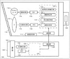
以下、図1を参照して、本発明の第1の実施例による、撮影システム1000の構成について説明する。撮影システム1000は、レンズ装置1100、操作装置1200、撮像装置1300で構成されている。レンズ装置1100の構成は、ズームレンズ(変倍手段、光学部材)1101、アクチュエータ1102、位置検出器1103、駆動回路1104、DAC1105、ADC1106、CPU1107、通信部1111である。さらに、レンズ装置1100は、不図示フォーカスレンズ、アイリス等の光学調整部材を含む撮影光学系、及びこれら光学調整部材の駆動手段で構成されている。レンズ装置1100には、レンズ装置によって形成される光学像を撮像する撮像素子1301を有する撮像装置1300が接続され、レンズ装置1100からの光を撮像素子1301で受光して光電変換する。さらに、レンズ装置1100は、操作装置1200が接続され、操作装置1200は、操作部1201、位置検出器1202、ADC1203、CPU1204、通信部1205で構成されている。
Hereinafter, with reference to FIG. 1, the structure of the imaging |
以下、各構成要素について説明をする。 Hereinafter, each component will be described.
レンズ装置1100について、ズームレンズ1101は、光軸方向に移動させることで焦点距離を変更する(変倍を行う)。アクチュエータ1102は、例えばモータであり、後述する駆動回路1104より、駆動信号が入力され、該駆動信号に基づいて、ズームレンズ1101を光軸方向に移動させる。DAC1105はDAコンバータで、デジタル信号をアナログ信号に変換する。ADC1106はADコンバータでアナログ信号をデジタル信号に変換する。位置検出器1103は、例えばエンコーダであり、ズームレンズ1101と、ギアを介して接続され、ズームレンズ1101の移動量に応じてパルスを発生する。発生したパルスはADC1106でデジタル信号に変換し、CPU1107に入力される。CPU1107では、入力されたパルスをカウントすることで、ズームレンズ1101の位置を演算する。さらに、CPU1107は前記位置を微分演算することでズームレンズ1101の速度を演算する。駆動回路1104は、DAC1105で変換されたアナログ信号に対し、増幅処理を行い、アクチュエータ1102に出力する。CPU1107は、画界変化率補正部(制御手段)1108と、速度補正部(制御手段)1109と、補正値記憶部1110で構成される。補正値記憶部1110は、レンズ装置1100の光軸方向の位置に対する焦点距離情報に基づく値(補正値)が記憶されている。このデータはレンズ装置固有のものであるため、予め記憶させておくことが好ましい。補正値については、後で詳細に説明する。また、CPU1107には後述する各種処理に必要となる閾値、プログラム等を記憶している。通信部1111は後述する操作装置1200から出力された指令値を受信し、CPU1107へ出力する。なお、画界変化率補正部1108、速度補正部1109については、後でより詳細に説明する。
With respect to the
操作装置1200は、操作部1201を有しており、該操作部1201はユーザーが操作しない場合は、例えばばね機構により、中央位置に戻るようになっている。また、ユーザーは操作部1201を中央位置(中立位置)から左右に操作(回転)することができる。その際、位置検出器1202により、操作部1201の操作量(回転角)を検出している。検出した操作量は、ADC1203によりデジタル信号に変換された後、CPU1204に出力される。CPU1204では、操作量に応じて、ズームレンズ1101を駆動させる速度を演算し、該速度を指令値として通信部1205に出力する。なお、CPU1204は、操作部1201の操作量に対して、ズームレンズ1101を駆動させる速度を演算する構成としたが、これに限らず、ズームレンズ1101の位置や駆動量を演算する構成としても良い。
The
以上のような撮影システム1000によって、ユーザーは被写体をその撮影画界を変更しながら撮影することができる。
With the
以下、図2を参照して、本実施例におけるレンズ装置1100のズーム位置と画界変化率の関係について説明する。図2に示すグラフの横軸はズームレンズ1101の位置を示しており、縦軸は画界変化率を示している。
Hereinafter, with reference to FIG. 2, the relationship between the zoom position of the
破線で示すのは、レンズ装置1100のズーム位置に対する画界変化率である。上述したように、ズーム位置に対して、画界変化率は一定でないことがわかる。前記破線で示すような画界変化率を略一定(図中実線)に補正(変更)するために、上述した、ズームレンズ1101を駆動する速度をズーム位置に応じて加減速させる方法がある。
なお本明細書内ではズーム位置とは、必ずしもズームレンズの光軸方向における物理的な位置を直接示すものでなくてもよい。例えば、ズーム駆動するためにカム機構を使用する場合のカム部材の変位位置を示す値であってもよいし、円筒カムでズーム駆動する場合には円筒カムの回転角に相当する値を指すものであってもよい。すなわち、ズーミングのために構成された可動レンズ、該可動レンズを駆動するためのカム等の駆動機構で構成される変倍手段の中で、可動レンズの位置に対して一意に確定する構成要素の位置(変倍手段の位置)であれば、実施例で例示したズームレンズ位置として本発明が適用できる。
A broken line indicates an image field change rate with respect to the zoom position of the
In the present specification, the zoom position does not necessarily directly indicate the physical position of the zoom lens in the optical axis direction. For example, it may be a value indicating the displacement position of the cam member when the cam mechanism is used for zoom driving, or it indicates a value corresponding to the rotation angle of the cylindrical cam when zoom driving is performed with the cylindrical cam. It may be. That is, among the zooming means composed of a movable lens configured for zooming and a driving mechanism such as a cam for driving the movable lens, a component that is uniquely determined with respect to the position of the movable lens If it is the position (position of the zooming means), the present invention can be applied as the zoom lens position exemplified in the embodiment.
以下、該方法について説明する。 The method will be described below.
図2において、位置Z12、Z50では補正前の画界変化率(破線)が、目標とする一定画界変化率(実線)よりも低い。そのため、ズームレンズ1101を所定速度分速く駆動すれば良い。一方、位置Z26、Z40では補正前の画界変化率(破線)が、目標とする一定画界変化率(実線)よりも高いため、ズームレンズ1101を所定速度分遅く駆動すれば良い。このような考え方に基づいて、ズームレンズ1101を広角端から望遠端まで加減速しながら駆動することで、画界変化率を略一定とすることができる。なお、広角端から望遠端まで移動するために必要な駆動時間が、補正前と補正後で同等の時間になるように、目標とする画界変化率の値(図中A)を設定するのが好ましい。
In FIG. 2, at the positions Z12 and Z50, the field change rate before correction (broken line) is lower than the target constant field change rate (solid line). Therefore, the
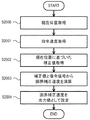
以下、図3乃至5を参照してCPU1107に構成される画界変化率補正部1108について説明する。画界変化率補正部1108では、上述した、加減速による画界変化率を略一定にする補正を行う。以下、図3に示したフローチャートに基づいて画界変化率補正部1108の動作を説明する。
Hereinafter, the field change
まず、CPU1107の処理はステップS2000に進み、ズームレンズ1101の現在位置を取得する。現在位置は前述したように、位置検出器1103より出力されたパルスに基づいて、CPU1107内部で演算することで得られる。次にステップS2001に進み指令速度を取得する。指令速度は前述したように、操作装置1200から、操作装置側の通信部1205および、レンズ装置1100側の通信部1111を介してCPU1107内に出力された速度(もしくはそれに基づいてCPU1107内で演算した速度)である。次にステップS2002では、補正値記憶部1110に記憶された補正値を取得する。
First, the processing of the
ここで、図4を用いて、CPU1107に記憶された補正値(補正情報)について説明する。図4はCPU1107に記憶された補正値の例を示している。表の左側の列(ズーム位置列)は、ズームレンズ1101の位置を示しており、広角端から望遠端までの位置を1から60までの相対値で示している。表の右側の列(補正データ列)は、ズーム位置におけるズームレンズ1101の補正値を示している。各ズーム位置における補正値は、例えば、前述した補正前の画界変化率(図2破線)と、補正目標とする一定画界変化率(図2実線)から演算することができるが、演算方法はこれに限らない。
Here, the correction value (correction information) stored in the
図3に戻り、ステップS2002では、例えば、ズームレンズ1101が2の位置にある場合、補正値は1.10を、25の位置にある場合は、0.88を取得する。次にステップS2003に進み、ステップS2001で取得した指令速度と、ステップS2003で取得した補正値を基に、画界変化率を略一定にする速度を演算し、ステップS2004で出力値として設定する。このように、画界変化率補正部1108により、操作装置1200からの指令速度を、ズームレンズ1101の焦点距離に基づく補正値で補正することで、画界変化率を略一定にする速度を、各ズーム位置に対して、得ることができる。
Returning to FIG. 3, in step S2002, for example, when the
図5には、指令速度、画界変化率補正部1108で演算される速度と、ズーム位置との関係を示す。図5(a)は横軸がズーム位置、縦軸は指令速度の大きさを示している。指令速度は0から100までの範囲で変化し、例えば、広角端位置から望遠端位置(可動範囲の全域、全可動範囲)まで、もしくは望遠端位置から広角端位置まで(以下、全域)、100の指令速度を入力し続けた際は、0.5秒で駆動し、20の指令速度を入力し続けた際は、90秒で駆動するものとする。今、操作装置1200を操作し、入力速度として「45」を広角端位置から望遠端位置まで入力し続けたとする。そのときの入力速度の波形を破線で示し、画界変化率補正部1108で補正した指令速度の波形を実線で示す。グラフ上に示す各代表位置(Z12、Z26、Z40、Z50)は、図2、4で示したZ12、Z26、Z40、Z50に相当する。
FIG. 5 shows the relationship between the command speed, the speed calculated by the field change
一方、図5(b)は図5(a)と対応しており、ズームの各代表位置における指令速度と補正値記憶部1110に記憶されている補正値を示している。図5(b)の第1行は操作装置1200からの入力速度(上図グラフの破線)、第2行は図4で示した補正値、第3行は画界変化率補正部1108で補正した画界補正速度(上図グラフの実線)である。例えばZ12の位置では、操作装置1200から入力された「45」の指令速度に対し、画界補正速度が「47.3」であることを示している。
On the other hand, FIG. 5B corresponds to FIG. 5A and shows the command speed at each zoom representative position and the correction value stored in the correction
なお、ここでは、Z50の位置における画界補正速度「63.5」が全域の画界補正速度の中で最大である。 Here, the field correction speed “63.5” at the position of Z50 is the maximum among the field correction speeds in the entire area.
このように、画界変化率補正部1108では画界変化率を略一定にするために、操作装置1200からの指令速度を補正(増減)している。
As described above, the field change
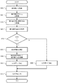
以下、図6に示したフローチャートを参照して、速度補正部1109について説明する。まず、CPU1107の処理は、ステップS600に進み、操作装置1200より出力される指令速度(Ctl)を取得する。次に、ステップS601に進み、画界変化率補正部1108により演算される画界補正速度(Ctlang)を取得し、ステップS602に進む。ステップS602では、最大画界補正速度(Ctlmax)を取得する。最大画界補正速度(Ctlmax)とは、ステップS600で取得したCtlを全域に渡って入力し続けたとした際、画界変化率補正部1108で演算される画界補正速度が最大のものを指す。例えば、図5を参考にすると、Z50で、補正速度(図中実線)が、最大になっている。このときの値(図中「63.5」)がCtlmaxである。Ctlmaxは、操作装置1200からの指令速度Ctlと、予め補正値記憶部1110内に記憶されている補正値に基づいて決定する。そのため、ズームレンズ1101がどの位置にあっても、Ctlが決まった時点で、Ctlmaxを演算できる。
Hereinafter, the
次に、ステップS603では、ズームレンズ1101が駆動可能な最高速度Spdmaxを取得する。Spdmaxは、予めCPU1107内の不図示メモリに記憶させておく。ステップS604では、最大画界補正速度Ctlmaxが所定の条件を満たしているか否かを判断する。具体的には、CtlmaxとSpdmaxを比べ、CtlmaxがSpdmaxよりも大きい場合はステップS605に進み、そうでない場合は、ステップS609に進む。ステップS605では式(1)に基づいて、補正係数Kを演算し、ステップS606に進む。
K=(Spdmax−Ctl)/(Ctlmax−Ctl) ・・・(1)
ここで、Spdmaxは、ステップS603で取得するズームレンズ1101の最高速度、CtlはステップS600で取得する操作装置1200からの指令速度、CtlmaxはステップS602で取得する最大画界補正速度である。
Next, in step S603, the maximum speed Spdmax at which the
K = (Spdmax−Ctl) / (Ctlmax−Ctl) (1)
Here, Spdmax is the maximum speed of the
ステップS606では、式(2)に基づいて補正値Ctladjを演算し、ステップS607に進む。
Ctladj=(Ctlang−Ctl)×K+Ctl ・・・(2)
ここで、Ctlangは、ステップS601で取得する画界補正速度である。
In step S606, a correction value Ctladj is calculated based on equation (2), and the process proceeds to step S607.
Ctladj = (Ctlang−Ctl) × K + Ctl (2)
Here, Ctlang is the field correction speed acquired in step S601.
ステップS607では、出力値にCtladjを設定し、ステップS608に進む。ステップS608では、出力値に設定された値を出力する。また、ステップS604にて、CtlmaxがSpdmaxよりも小さい場合は、SステップS609に進み、出力値にCtlangを設定する。 In step S607, Ctladj is set as the output value, and the process proceeds to step S608. In step S608, the value set as the output value is output. If Ctlmax is smaller than Spdmax in step S604, the process proceeds to step S609, and Ctlang is set as the output value.
図7には、ズーム各位置と、入力速度、画界補正速度、速度補正部1109で演算される速度(修正補正速度)との関係を示す。図7(a)に示すグラフの横軸、縦軸は図5(a)と同等である。図5では、入力速度として操作装置1200から「45」を広角端位置から望遠端位置まで入力し続けた例を示したが、図7では入力速度として「80」を広角端位置から望遠端位置まで入力し続けた例を示す。破線で示す波形は入力速度、一点鎖線で示す波形は画界補正速度、実線で示す波形は修正補正速度を示す。グラフ上に示す各代表位置(Z12、Z26、Z40、Z50)は、図2、4、5で示したZ12、Z26、Z40、Z50に相当する。また、斜線部は、画界補正速度が最高速度以上である領域、つまり、速度「100」を超えている領域を示している。
FIG. 7 shows the relationship between each zoom position, the input speed, the field correction speed, and the speed calculated by the speed correction unit 1109 (correction correction speed). The horizontal and vertical axes of the graph shown in FIG. 7A are the same as those in FIG. 5 shows an example in which “45” is continuously input from the
図5と同様、下に示した図7(b)は図7(a)と対応しており、ズームの各代表位置における指令速度と補正値記憶部1110に記憶されている補正値を示している。表の第1行は入力速度(図7(a)の破線)、第2行は図4で示した補正値、第3行は画界補正速度(上図グラフの一点鎖線)である。さらに、第4行は修正補正速度(上図グラフの実線)を示している。それぞれの波形は、図6のフローチャートで示した記号を用いると、破線は「Ctl」、一点鎖線は「Ctlang」、実線は「Ctladj」である。
Like FIG. 5, FIG. 7B shown below corresponds to FIG. 7A, and shows the command speed at each zoom representative position and the correction value stored in the correction
例えば、現在位置がZ11で、操作装置1200から「45」の速度を入力したとする。このとき、図5(b)より、Ctlmaxは63.5であり、これはSpdmax(100)よりも小さい。そのため、図6のステップS604の判断(Ctlmax>Spdmax?)で、ステップS609に進み、Z11の位置での出力値はCtlang(47.3)が設定される。一方、現在位置Z11で、操作装置1200から「80」の速度を入力した場合、図7(b)よりCtlmaxは112.8であり、これはSpdmax(100)よりも大きい。そのため、図6のステップS604の判断(Ctlmax>Spdmax?)で、ステップS605に進み、最終的にZ11の位置での出力値は、Ctladj(82.7)が設定される。
For example, it is assumed that the current position is Z11 and a speed of “45” is input from the
以上のように、最大画界補正速度がズーム最高速度を越える場合、速度補正部1109は、式1に示す係数Kを用いて速度を演算する。このとき、最大画界補正速度がズーム最高速度と同等になるよう、前記係数Kが決定するため、速度補正部1109で演算される速度は、どのズームレンズ位置においても最高速度以下とすることができる。また、図7(b)のZ50列を参照すると、画界補正速度が「112.8」であるのに対し、修正補正速度は「100.0」であり、画界補正速度に対し、値を減少させている。一方、Z26列を参照すると、画界補正速度が「70.4」であるのに対し、修正補正速度は「73.6」であり、値を増加させている。これは言い換えれば、速度補正部1109において、図7(a)で示す一点鎖線の波形の振幅を一定割合(係数K)分小さくしている。このように、図7(a)斜線部の速度を低くした分だけ、他の位置(Z26、Z40など)での速度を速くすることで、加速分と、減速分を同等にし、全域駆動した際の速度を、補正前と同等にしている。
As described above, when the maximum field correction speed exceeds the maximum zoom speed, the
従来は、ズーム速度を加減速して、画界変化率を略一定にしようとすると、ズームの駆動可能速度(最高速度)を上回って駆動しなければならない区間が生じる。そのため該区間では所望の画界変化率補正ができない可能性があった。また、前記区間では、最高速度以上の速度でズームを駆動しなければならないのに対し、実際のズームの速度は最高速度に制限されるため、駆動時間が長くなる可能性がある。加えて、前記最高速度への制限により、急な加速度の変化が生じ、撮影映像に違和感を与る可能性があった。 Conventionally, when the zoom speed is accelerated and decelerated to make the field-of-field change rate substantially constant, there is a section in which the zoom must be driven above the maximum drive speed (maximum speed). Therefore, there is a possibility that a desired field-of-field change rate correction cannot be performed in the section. Further, in the section, the zoom must be driven at a speed equal to or higher than the maximum speed, whereas the actual zoom speed is limited to the maximum speed, so that the drive time may be long. In addition, due to the limitation to the maximum speed, a sudden change in acceleration may occur, which may give a sense of incongruity to the captured image.
これに対し、本実施例では、画界変化率を略一定にする補正において、所定の位置で最高速度を超える速度指令が演算される場合、該速度指令を減少し最高速度範囲内に収まるようにする。さらに、前記減少した分だけ、他の位置での速度指令を増加させる。すなわち、一定速度で光学部材を駆動した場合の画界変化率の変動よりも画界変化率の変動が小さく、最高速度範囲内で、全駆動範囲の駆動時間は変わらない速度指令を導出し、それに基づいてズームを駆動する。ここで、変動とは変動幅や変動頻度、変動速度などで評価できるものである。そのため、前述した従来の課題を解消する効果がある。 On the other hand, in this embodiment, when a speed command exceeding the maximum speed is calculated at a predetermined position in the correction for making the field change rate substantially constant, the speed command is decreased so that it falls within the maximum speed range. To. Further, the speed command at another position is increased by the decreased amount. That is, the fluctuation of the field change rate is smaller than the change of the field change rate when the optical member is driven at a constant speed, and a speed command in which the drive time of the entire drive range does not change is derived within the maximum speed range, Drive the zoom based on it. Here, the fluctuation can be evaluated by a fluctuation width, a fluctuation frequency, a fluctuation speed, or the like. Therefore, there is an effect of solving the above-described conventional problems.
なお、本実施例では操作装置1200からの指令速度がズーム全域に渡って一定であることを前提に説明をしたが、これに限らず、操作装置1200からの指令速度はズーム駆動中に変化させてもよい。
In this embodiment, the description has been made on the assumption that the command speed from the
さらに、本実施例では、ズームレンズ1101の補正に関する説明をしたが、これに限らず、フォーカスレンズや絞りなどの光学調整部材に対しても適用可能である。
Furthermore, in the present embodiment, the correction of the
以下、図8を参照して、本発明の第2の実施例について説明する。 The second embodiment of the present invention will be described below with reference to FIG.
実施例1では、画界変化率を略一定にする指令速度が、ズームレンズ1101の駆動可能な速度(最高速度)を上回る速度であった場合、速度補正部1109において、駆動可能な速度範囲内に演算した。
In the first embodiment, when the command speed that makes the field change rate substantially constant is higher than the speed (maximum speed) at which the
本実施例では、画界変化率を略一定にする指令速度が、ズームレンズ1101の所定の速度を下回る速度であった場合、速度補正部1109において、指令速度を演算し、出力する。
In this embodiment, when the command speed that makes the field-of-view change rate substantially constant is lower than the predetermined speed of the
本実施例における撮影システム1000の構成については、実施例1と同様の構成要素であるため、説明を省略する。
Since the configuration of the
以下、図8を参照して本実施例における速度補正部1109の処理について説明する。なお、実施例1の図6と同様のフローについては、同一の符号で示し、説明を省略する。
Hereinafter, the processing of the
ステップS800では、最小画界補正速度(Ctlmin)を取得する。Ctlminは、実施例1の図6で示したCtlmaxとは反対に、画界変化率補正部1108で演算される指令速度が最小のものを指す。CtlminもCtlmaxと同様に、ズームレンズ1101がどの位置にあっても、Ctlが決まった時点で決定する値である。
In step S800, the minimum field correction speed (Ctlmin) is acquired. Ctlmin indicates the minimum command speed calculated by the field change
次に、ステップS801に進み、ズームレンズ1101の最低速度Spdminを取得し、ステップS802に進む。Spdminは、ズームレンズ1101がスムーズに動作できる速度のうち、最も低い速度を設定するのが好ましい。Spdminは予めCPU1107内の不図示メモリに記憶させておく。ステップS802では、最小画界補正速度Ctlminが所定の条件を満たしているか否かを判断する。具体的には、CtlminとSpdminを比べ、CtlminがSpdminよりも小さい場合はステップS605に進み、そうでない場合は、ステップS609に進む。なお、ステップS605では、式3に基づいて係数Kを演算する。
K=(Spdmin−Ctl)/(Ctlmin−Ctl) ・・・(3)
Next, the process proceeds to step S801, the minimum speed Spdmin of the
K = (Spdmin−Ctl) / (Ctlmin−Ctl) (3)
以上説明したように、本実施例ではズームレンズ1101の最低速度Spdminを下回る場合、速度補正部1109で、どのズームレンズ位置においても最低速度以上となる指令速度を演算し、出力する。
As described above, in this embodiment, when the speed is lower than the minimum speed Spdmin of the
上述したように、一般的に最低速度とは、ズームレンズ1101がスムーズに動作できる速度のうち、最も低い速度を設定する。一般に、操作装置で可動レンズを駆動する場合、可動レンズは0より大きい速度での駆動が可能であるが、安定した駆動を保証するための制御上の制約や、装置のハード上の制約のために、通常の使用において最低速度を設定している。そのため、最低速度よりも低い速度指令でズームレンズ1101を駆動すると、指令を与えているにも関わらず、途中停止したり、駆動と停止を繰り返したりする動きになり、撮影映像に違和感を与える。本実施例では、画界変化率を略一定にするために、最低速度よりも低い速度指令が必要になる際は、速度補正部1109にて、最低速以上の速度に制限する事ができる。したがって、上記のような違和感を軽減する事ができる。
As described above, generally, the minimum speed is set to the lowest speed among the speeds at which the
以下、図9乃至10を参照して、本発明の第3の実施例について説明する。 The third embodiment of the present invention will be described below with reference to FIGS.
実施例1では、画界変化率を略一定にする指令値が、ズームレンズ1101の最高速を上回る指令値であった場合、速度補正部1109において、駆動可能な速度範囲内に収める指令値を演算し、出力した。
In the first embodiment, when the command value that makes the field change rate substantially constant is a command value that exceeds the maximum speed of the
また、実施例2では、画界変化率を略一定にする指令値が、ズームレンズ1101の最低速を下回る指令値であった場合、速度補正部1109において、最低速以上の速度に収める速度指令を演算し、出力した。
In the second embodiment, when the command value that makes the field-of-view change rate substantially constant is a command value that is lower than the minimum speed of the
本実施例では、画界変化率を略一定にする指令速度が、ユーザーが設定可能な所定速度の範囲外であった場合、速度補正部1109において、所定速度の範囲内に収める指令速度を演算し、出力する。
In this embodiment, when the command speed that makes the field-of-view change rate substantially constant is out of a predetermined speed range that can be set by the user, the
本実施例における撮影システム1000の構成について、図9を参照して説明する。なお、実施例1と同様の構成要素については、同一の符号で示し、説明を省略する。
The configuration of the
図9における速度設定部(設定手段)1112は、ユーザーが操作可能であり、ズームレンズ1101の最大の駆動速度を設定する。速度記憶部(条件記憶手段)1113は速度設定部1112で設定した最大の駆動速度Spduserを記憶する。以上説明した最大の駆動速度は、上述したように、速度補正部1109内の処理で用いられる。
A speed setting unit (setting unit) 1112 in FIG. 9 is operable by the user and sets the maximum driving speed of the
以下、図10を参照して本実施例における速度補正部1109の処理について説明する。なお、実施例1の図6と同様のフローについては、同一の符号で示し、説明を省略する。
Hereinafter, the processing of the
ステップS1000では、速度記憶部1113に記憶されたズームレンズ1101の駆動速度Spduserを取得し、ステップS901に進む。ステップS1001では、最大画界補正速度Ctlmaxが所定の条件を満たしているか否かを判断する。具体的には、CtlmaxとSpduserを比べ、CtlmaxがSpduserよりも大きい場合はステップS605に進み、そうでない場合は、ステップS609に進む。
In step S1000, the drive speed Spduser of the
以上説明したように、本実施例ではユーザーが速度設定する設定部と、設定した速度を記憶する記憶部を設け、記憶部に記憶された速度を基に、速度補正部1109での指令速度を演算する。
As described above, in this embodiment, the setting unit for setting the speed by the user and the storage unit for storing the set speed are provided, and the command speed in the
一般にアクチュエータは、駆動する際に音を発生し、その音はアクチュエータの駆動速度が速くなるに連れて大きくなる。そのため、例えば動画撮影では、高速駆動時のアクチュエータの駆動音が撮影映像時の音声に重畳される場合がある。本実施例では、画界変化率を略一定にする指令速度が設定速度以上である場合には、速度補正部1109にて、前記設定速度に制限する事ができる。したがって、アクチュエータの駆動音が撮影映像に与える影響を軽減する事ができる。
In general, an actuator generates a sound when driven, and the sound increases as the driving speed of the actuator increases. For this reason, for example, in moving image shooting, the drive sound of the actuator during high-speed driving may be superimposed on the sound during shooting video. In this embodiment, when the command speed for making the field change rate substantially constant is equal to or higher than the set speed, the
なお、本実施例は速度設定部1112で設定した速度を上限速度として、速度補正部1109で速度指令を演算した。しかし、これに限らず、速度設定部1112で設定する速度は下限速度でもよい。また、上下限速度を設定するような速度範囲を設定できるようにしてもよい。ズームレンズの移動速度の上限や下限、又は、上下限の条件値を設定できるようにしてもよい。
In this embodiment, the speed set by the
画界は撮像範囲であり、像面と共役関係にある物体距離の平面における、イメージサイズに対応する長さである。画界変化率は、ズーム操作するために駆動対象を駆動手段により一定の速度で駆動した時の、単位時間当たりの画界の変化率である。 The field of view is the imaging range, and is the length corresponding to the image size in the plane of the object distance that is conjugate with the image plane. The field of view change rate is the rate of change of the field of view per unit time when the object to be driven is driven at a constant speed by the driving means for zooming operation.
なお本明細書内ではズームレンズ位置(ズーム位置)とは、必ずしもズームレンズの光軸方向における物理的な位置を直接示すものでなくてもよい。例えば、ズーム駆動するためにカム機構を使用する場合のカム部材の変位位置を示す値であってもよいし、円筒カムでズーム駆動する場合には円筒カムの回転角に相当する値を指すものであってもよい。すなわち、ズーミングのために構成された可動レンズ、該レンズを駆動するためのカム等の駆動機構等で構成される光学部材の中で、可動レンズの位置に対して一意に確定する構成要素の位置(光学部材の位置)であれば、上記実施例で例示したズームレンズ位置として本発明が適用できる。 In the present specification, the zoom lens position (zoom position) does not necessarily directly indicate the physical position of the zoom lens in the optical axis direction. For example, it may be a value indicating the displacement position of the cam member when the cam mechanism is used for zoom driving, or it indicates a value corresponding to the rotation angle of the cylindrical cam when zoom driving is performed with the cylindrical cam. It may be. That is, the position of a component that is uniquely determined with respect to the position of the movable lens among optical members including a movable lens configured for zooming and a driving mechanism such as a cam for driving the lens. If it is (the position of the optical member), the present invention can be applied as the zoom lens position exemplified in the above embodiment.
以上、本発明の好ましい実施形態について説明したが、本発明はこれらの実施形態に限定されず、その要旨の範囲内で種々の変形及び変更が可能である。 As mentioned above, although preferable embodiment of this invention was described, this invention is not limited to these embodiment, A various deformation | transformation and change are possible within the range of the summary.
1100 レンズ装置
1101 ズームレンズ(光学部材)
1102 アクチュエータ(駆動手段)
1108 画界変化率補正部(制御手段)
1109 速度補正部(制御手段)
1110 補正値記憶部(記憶手段)
1200 操作装置(入力手段)
1100
1102 Actuator (drive means)
1108 Field change rate correction unit (control means)
1109 Speed correction unit (control means)
1110 Correction value storage unit (storage means)
1200 Operating device (input means)
Claims (9)
前記変倍手段を駆動する駆動手段と、
前記変倍手段の速度指令を入力する入力手段と、
前記変倍手段の可動範囲の全域において、前記入力手段により入力された速度指令により前記変倍手段を駆動する場合よりも画界変化率が一定に近づき、かつ、所定の条件を満たす速度指令を導出する制御手段と、
を有することを特徴とするレンズ装置。 Scaling means driven for scaling,
Driving means for driving the scaling means;
Input means for inputting a speed command of the scaling means;
A speed command in which the field-of-view change rate approaches a constant value and satisfies a predetermined condition over the entire movable range of the power scaling unit, compared to the case where the power scaling unit is driven by a speed command input by the input unit. Deriving control means;
A lens device comprising:
前記制御手段は、前記入力された速度指令と前記補正情報に基づき、前記所定の条件を満たす速度指令を導出する、
ことを特徴とする請求項1に記載のレンズ装置。 Storage means for storing correction information based on the relationship between the position of the scaling means and the field of view,
The control means derives a speed command that satisfies the predetermined condition based on the input speed command and the correction information.
The lens device according to claim 1.
前記入力された速度指令と前記補正情報に基づき、前記可動範囲の全域における画界変化率を一定に近づける、前記変倍手段の位置に対する第1の速度指令を演算し、
前記第1の速度指令が前記可動範囲の全域において所定の条件を満たす場合は、前記第1の速度指令を前記所定の条件を満たす速度指令とし、
前記第1の速度指令が所定の条件を満たさない前記変倍手段の位置がある場合は、前記入力された速度指令と前記補正情報に基づき、前記可動範囲の全域における画界変化率を一定に近づけるような第2の速度指令であって、前記可動範囲の全域において所定の条件を満たし、かつ、前記第1の速度指令で前記可動範囲の全域を駆動した場合の駆動時間と同じ駆動時間となるような第2の速度指令を導出し、該第2の速度指令を前記所定の条件を満たす速度指令とする、
ことを特徴とする請求項2又は3に記載のレンズ装置。 The control means includes
Based on the input speed command and the correction information, calculate a first speed command for the position of the zooming unit, which brings the field change rate in the entire movable range close to a constant value,
When the first speed command satisfies a predetermined condition over the entire movable range, the first speed command is a speed command that satisfies the predetermined condition,
If there is a position of the zooming unit that does not satisfy a predetermined condition in the first speed command, the field change rate in the entire movable range is made constant based on the input speed command and the correction information. A second speed command for approaching, a predetermined time in the entire range of the movable range, and a drive time equal to a drive time when the entire range of the movable range is driven by the first speed command. A second speed command is derived, and the second speed command is set as a speed command that satisfies the predetermined condition.
The lens device according to claim 2 or 3, wherein
前記所定の条件は前記設定手段で設定された前記条件値の範囲内である、
ことを特徴とする請求項1乃至4のいずれか1項に記載のレンズ装置。 Setting means for setting a condition value of the driving speed of the scaling means;
The predetermined condition is within the range of the condition value set by the setting means.
The lens device according to claim 1, wherein the lens device is a lens device.
Priority Applications (2)
| Application Number | Priority Date | Filing Date | Title |
|---|---|---|---|
| JP2015081282A JP6553928B2 (en) | 2015-04-10 | 2015-04-10 | Lens device and photographing system having the same |
| US15/093,076 US10382697B2 (en) | 2015-04-10 | 2016-04-07 | Lens apparatus and image pickup system having the same |
Applications Claiming Priority (1)
| Application Number | Priority Date | Filing Date | Title |
|---|---|---|---|
| JP2015081282A JP6553928B2 (en) | 2015-04-10 | 2015-04-10 | Lens device and photographing system having the same |
Publications (3)
| Publication Number | Publication Date |
|---|---|
| JP2016200737A true JP2016200737A (en) | 2016-12-01 |
| JP2016200737A5 JP2016200737A5 (en) | 2018-05-31 |
| JP6553928B2 JP6553928B2 (en) | 2019-07-31 |
Family
ID=57111327
Family Applications (1)
| Application Number | Title | Priority Date | Filing Date |
|---|---|---|---|
| JP2015081282A Expired - Fee Related JP6553928B2 (en) | 2015-04-10 | 2015-04-10 | Lens device and photographing system having the same |
Country Status (2)
| Country | Link |
|---|---|
| US (1) | US10382697B2 (en) |
| JP (1) | JP6553928B2 (en) |
Families Citing this family (2)
| Publication number | Priority date | Publication date | Assignee | Title |
|---|---|---|---|---|
| JP6598490B2 (en) * | 2015-04-10 | 2019-10-30 | キヤノン株式会社 | Lens apparatus and imaging apparatus having the same |
| JP7154974B2 (en) * | 2018-11-28 | 2022-10-18 | キヤノン株式会社 | Operating device, lens device, and imaging device |
Citations (5)
| Publication number | Priority date | Publication date | Assignee | Title |
|---|---|---|---|---|
| JPH02125216A (en) * | 1988-11-02 | 1990-05-14 | Nikon Corp | Zoom lens device for camera |
| JP2006196965A (en) * | 2005-01-11 | 2006-07-27 | Canon Inc | Optical apparatus |
| JP2012022123A (en) * | 2010-07-14 | 2012-02-02 | Nikon Corp | Interchangeable lens and imaging apparatus |
| JP2012042554A (en) * | 2010-08-16 | 2012-03-01 | Canon Inc | Lens control apparatus |
| JP2014154905A (en) * | 2013-02-05 | 2014-08-25 | Canon Inc | Imaging apparatus, remote operation terminal, camera system, imaging apparatus control method and program, and remote operation terminal control method and program |
Family Cites Families (3)
| Publication number | Priority date | Publication date | Assignee | Title |
|---|---|---|---|---|
| US5905530A (en) * | 1992-08-24 | 1999-05-18 | Canon Kabushiki Kaisha | Image pickup apparatus |
| JPH11211962A (en) | 1998-01-22 | 1999-08-06 | Canon Inc | Television lens |
| JP6598490B2 (en) * | 2015-04-10 | 2019-10-30 | キヤノン株式会社 | Lens apparatus and imaging apparatus having the same |
-
2015
- 2015-04-10 JP JP2015081282A patent/JP6553928B2/en not_active Expired - Fee Related
-
2016
- 2016-04-07 US US15/093,076 patent/US10382697B2/en not_active Expired - Fee Related
Patent Citations (5)
| Publication number | Priority date | Publication date | Assignee | Title |
|---|---|---|---|---|
| JPH02125216A (en) * | 1988-11-02 | 1990-05-14 | Nikon Corp | Zoom lens device for camera |
| JP2006196965A (en) * | 2005-01-11 | 2006-07-27 | Canon Inc | Optical apparatus |
| JP2012022123A (en) * | 2010-07-14 | 2012-02-02 | Nikon Corp | Interchangeable lens and imaging apparatus |
| JP2012042554A (en) * | 2010-08-16 | 2012-03-01 | Canon Inc | Lens control apparatus |
| JP2014154905A (en) * | 2013-02-05 | 2014-08-25 | Canon Inc | Imaging apparatus, remote operation terminal, camera system, imaging apparatus control method and program, and remote operation terminal control method and program |
Also Published As
| Publication number | Publication date |
|---|---|
| JP6553928B2 (en) | 2019-07-31 |
| US20160299314A1 (en) | 2016-10-13 |
| US10382697B2 (en) | 2019-08-13 |
Similar Documents
| Publication | Publication Date | Title |
|---|---|---|
| JP5328384B2 (en) | LENS CONTROL DEVICE, OPTICAL DEVICE, AND LENS CONTROL METHOD | |
| JP6366230B2 (en) | Imaging device, control method thereof, and control program | |
| JP3610167B2 (en) | Lens control method and apparatus | |
| JP2013130827A (en) | Lens control device | |
| US8526805B2 (en) | Lens apparatus and camera system including the same | |
| JP6553928B2 (en) | Lens device and photographing system having the same | |
| JP2009075221A (en) | Camera-shake correction device, and camera body and replacement lens provided therewith | |
| US5742435A (en) | Video-camera imaging-system zoom lens barrel | |
| JP2017181979A (en) | Lens controller and control method | |
| JP2013231820A (en) | Lens device and image capturing device having the same | |
| JP6468707B2 (en) | Imaging apparatus and control method thereof | |
| JP2017009961A (en) | Optical instrument and focus control program | |
| JP2021067704A (en) | Imaging device | |
| JP2021047296A (en) | Lens device, imaging apparatus, method for controlling lens device, and program | |
| JP2021067710A (en) | Lens control device, optical instrument, and lens control method | |
| JP4721394B2 (en) | LENS CONTROL DEVICE, OPTICAL DEVICE, AND LENS CONTROL METHOD | |
| JP7404059B2 (en) | Control device, lens device, imaging device, and imaging system | |
| JP7427414B2 (en) | Control device, lens device, imaging device, control method, program | |
| US8532477B2 (en) | Lens control device having lens position control function for bringing, method of controlling the same, and storage medium | |
| US11829000B2 (en) | Optical apparatus, its control method, and storage medium | |
| JP4721395B2 (en) | LENS CONTROL DEVICE, OPTICAL DEVICE, AND LENS CONTROL METHOD | |
| JPH02144509A (en) | Lens position controller | |
| JP7175677B2 (en) | optical equipment | |
| US10209481B2 (en) | Lens apparatus and image pickup apparatus having lens apparatus | |
| US20200007776A1 (en) | Lens apparatus and image pickup apparatus |
Legal Events
| Date | Code | Title | Description |
|---|---|---|---|
| RD05 | Notification of revocation of power of attorney |
Free format text: JAPANESE INTERMEDIATE CODE: A7425 Effective date: 20171214 |
|
| RD04 | Notification of resignation of power of attorney |
Free format text: JAPANESE INTERMEDIATE CODE: A7424 Effective date: 20180126 |
|
| A521 | Request for written amendment filed |
Free format text: JAPANESE INTERMEDIATE CODE: A523 Effective date: 20180410 |
|
| A621 | Written request for application examination |
Free format text: JAPANESE INTERMEDIATE CODE: A621 Effective date: 20180410 |
|
| A977 | Report on retrieval |
Free format text: JAPANESE INTERMEDIATE CODE: A971007 Effective date: 20190130 |
|
| A131 | Notification of reasons for refusal |
Free format text: JAPANESE INTERMEDIATE CODE: A131 Effective date: 20190219 |
|
| A521 | Request for written amendment filed |
Free format text: JAPANESE INTERMEDIATE CODE: A523 Effective date: 20190422 |
|
| TRDD | Decision of grant or rejection written | ||
| A01 | Written decision to grant a patent or to grant a registration (utility model) |
Free format text: JAPANESE INTERMEDIATE CODE: A01 Effective date: 20190606 |
|
| A61 | First payment of annual fees (during grant procedure) |
Free format text: JAPANESE INTERMEDIATE CODE: A61 Effective date: 20190705 |
|
| R151 | Written notification of patent or utility model registration |
Ref document number: 6553928 Country of ref document: JP Free format text: JAPANESE INTERMEDIATE CODE: R151 |
|
| LAPS | Cancellation because of no payment of annual fees |