JP2016200399A - Surface shape measurement device and surface shape measurement method - Google Patents
Surface shape measurement device and surface shape measurement method Download PDFInfo
- Publication number
- JP2016200399A JP2016200399A JP2015078282A JP2015078282A JP2016200399A JP 2016200399 A JP2016200399 A JP 2016200399A JP 2015078282 A JP2015078282 A JP 2015078282A JP 2015078282 A JP2015078282 A JP 2015078282A JP 2016200399 A JP2016200399 A JP 2016200399A
- Authority
- JP
- Japan
- Prior art keywords
- surface shape
- sensor
- measurement
- actuator
- moving
- Prior art date
- Legal status (The legal status is an assumption and is not a legal conclusion. Google has not performed a legal analysis and makes no representation as to the accuracy of the status listed.)
- Pending
Links
Images
Landscapes
- Length Measuring Devices With Unspecified Measuring Means (AREA)
Abstract
Description
本発明は、表面形状測定装置及び表面形状測定方法に関する。 The present invention relates to a surface shape measuring device and a surface shape measuring method.
表面形状測定装置として、触針を利用した接触式のものや(特許文献1)、レーザー光を利用した非接触式のもの(特許文献2)などが知られている。これら表面形状測定装置において、一般に、ミリメートルオーダーの凹凸形状を測定するための装置は広い測定範囲を有する一方で表面粗さの測定に要求されるようなナノメートルオーダーの分解能は有しておらず、表面粗さを測定するための装置はナノメートルオーダーの高い測定分解能を有する一方でミリメートルオーダーの広い測定範囲は有していない。そのため、例えばミリメートルオーダーの段差を有する部材の全体形状とその表面粗さとを両方測定する場合には、複数の別の測定装置を使って、全体形状と、微細な表面粗さとを別々に測定する必要があった。 As a surface shape measuring device, a contact type using a stylus (Patent Document 1), a non-contact type using a laser beam (Patent Document 2), and the like are known. In these surface shape measuring devices, in general, devices for measuring irregularities on the order of millimeters have a wide measurement range, but do not have the resolution on the order of nanometers required for measuring surface roughness. An apparatus for measuring surface roughness has a high measurement resolution on the order of nanometers, but does not have a wide measurement range on the order of millimeters. Therefore, for example, when measuring both the overall shape and the surface roughness of a member having a step on the order of millimeters, the overall shape and the fine surface roughness are measured separately using a plurality of separate measuring devices. There was a need.
しかしながら、複数の別の測定装置で測定をする手法では、測定対象物を装置に何度もセッティングしなければならず、また別々に測定したデータを整合させる必要もあり、測定に多くの時間と手間がかかっていた。 However, in the method of measuring with a plurality of different measuring devices, it is necessary to set the object to be measured many times on the device, and it is also necessary to align the data measured separately, which takes a lot of time for the measurement. It took time and effort.
本発明は上記問題に鑑み、1つの測定装置で被測定物の全体形状から表面粗さまでを測定することが可能となるような表面形状測定装置及び表面形状測定方法を提供することを目的とする。 In view of the above problems, an object of the present invention is to provide a surface shape measuring device and a surface shape measuring method that enable measurement from the entire shape of the object to be measured to the surface roughness with a single measuring device. .
すなわち本発明は、
装置基部と、
該装置基部に設定され、被測定物を支持するステージと、
該装置基部に設定され、該ステージによって支持されている被測定物の表面形状を測定するための表面形状センサユニットと、
該ステージを該表面形状センサユニットに対して相対的に移動させる移動機構と、
を備える表面形状測定装置であって、
該表面形状センサユニットが、
所定の測定軸線の方向での所定幅をもった検出限界を有し、該測定軸線と交わる物体表面上の点を測定点として、該測定軸線の方向での該検出限界内における該測定点の位置を測定する第1センサと、
該第1センサを保持する第1アクチュエータであって、該検出限界の幅よりも広い該測定軸線の方向での所定幅をもった第1可動範囲を有し、該測定点が該検出限界内に位置するように該第1センサを該第1可動範囲内で該測定軸線の方向で移動させる第1アクチュエータと、
該第1アクチュエータによる該第1センサの移動距離を測定する第2センサと、
該第1アクチュエータを保持する第2アクチュエータであって、該第1可動範囲の幅よりも広い該測定軸線の方向での所定幅をもった第2可動範囲を有し、該第1アクチュエータが該第1センサを該第1可動範囲内で移動させて該測定点を該検出限界内に位置させることができるように、該第1アクチュエータを該第2可動範囲内で該測定軸線の方向で移動させる第2アクチュエータと、
該第2アクチュエータによる該第1アクチュエータの移動距離を測定する第3センサと、を備え、
該移動機構によって該第1センサの該測定点が被測定物の表面上を相対的に移動していくように該ステージと該第1センサとを相対的に移動させたときの、該第1、第2、及び第3センサの出力値に基づいて被測定物の表面形状を測定するようにされた、表面形状測定装置を提供する。
That is, the present invention
A device base;
A stage set at the base of the apparatus and supporting the object to be measured;
A surface shape sensor unit for measuring the surface shape of an object to be measured which is set in the apparatus base and supported by the stage;
A moving mechanism for moving the stage relative to the surface shape sensor unit;
A surface shape measuring device comprising:
The surface shape sensor unit is
A detection limit having a predetermined width in the direction of a predetermined measurement axis, and a point on the surface of the object that intersects the measurement axis as a measurement point, the measurement point within the detection limit in the direction of the measurement axis A first sensor for measuring the position;
A first actuator for holding the first sensor, having a first movable range having a predetermined width in the direction of the measurement axis that is wider than the width of the detection limit, and the measurement point is within the detection limit; A first actuator for moving the first sensor in the direction of the measurement axis within the first movable range so as to be positioned at
A second sensor for measuring a moving distance of the first sensor by the first actuator;
A second actuator that holds the first actuator and has a second movable range having a predetermined width in the direction of the measurement axis that is wider than the width of the first movable range; The first actuator is moved in the direction of the measurement axis within the second movable range so that the first sensor can be moved within the first movable range to position the measurement point within the detection limit. A second actuator,
A third sensor for measuring a movement distance of the first actuator by the second actuator,
The first stage when the stage and the first sensor are moved relative to each other so that the measurement point of the first sensor moves relatively on the surface of the object to be measured by the moving mechanism. Provided is a surface shape measuring device configured to measure the surface shape of an object to be measured based on output values of second and third sensors.
当該表面形状測定装置においては、被測定物の表面を直接的に測定する第1センサを、第1可動範囲を有する第1アクチュエータと第1可動範囲よりも広い第2可動範囲を有する第2アクチュエータとによって測定軸線の方向で変位させることにより、第1センサで測定可能な測定軸線の方向での範囲を大幅に拡大することができるようになっている。これにより、第1センサの測定分解能で、第1及び第2可動範囲の広い範囲内において表面形状を測定することが可能となるため、従来複数の別の測定装置により測定する必要があった大きな段差等がある被測定物に対しても、一つの測定装置でその表面形状を測定することが可能となる。 In the surface shape measuring apparatus, the first sensor that directly measures the surface of the object to be measured includes the first actuator having the first movable range and the second actuator having the second movable range wider than the first movable range. By displacing in the direction of the measurement axis, the range in the direction of the measurement axis that can be measured by the first sensor can be greatly expanded. As a result, the surface shape can be measured within the wide range of the first and second movable ranges with the measurement resolution of the first sensor, so that it has been necessary to measure with a plurality of separate measuring devices in the past. Even for an object to be measured having a step or the like, the surface shape can be measured with one measuring device.
好ましくは、該第1アクチュエータが、該検出限界内に位置する測定基準点を有し、該表面形状センサユニットによる被測定物の表面形状測定の最中に、該測定点が該測定基準点に近づくように該第1センサを連続的に移動させるようにすることができる。 Preferably, the first actuator has a measurement reference point located within the detection limit, and the measurement point becomes the measurement reference point during the surface shape measurement of the object to be measured by the surface shape sensor unit. The first sensor can be continuously moved so as to approach.
このような構成により、例えば測定基準点を検出限界の中心付近に設定しておくことによって、測定点が検出限界から外れてしまう可能性を低減させることが可能となる。 With such a configuration, for example, by setting the measurement reference point near the center of the detection limit, it is possible to reduce the possibility that the measurement point falls outside the detection limit.
好ましくは、該第2アクチュエータが、該表面形状センサユニットによる被測定物の表面形状測定の最中には該第1アクチュエータを移動させないようにすることができる。 Preferably, the second actuator may be configured not to move the first actuator during the surface shape measurement of the object to be measured by the surface shape sensor unit.
具体的には、該検出限界の幅が1マイクロメートル以上0.1ミリメートル未満であり、該第1可動範囲の幅が0.1ミリメートル以上2ミリメートル未満であり、該第2可動範囲の幅が10ミリメートル以上であるようにすることができる。 Specifically, the width of the detection limit is 1 micrometer or more and less than 0.1 millimeter, the width of the first movable range is 0.1 millimeter or more and less than 2 millimeters, and the width of the second movable range is It can be 10 millimeters or more.
また具体的には、該第1アクチュエータがピエゾアクチュエータであり、該第2アクチュエータがモータ駆動の直動テーブルであり、該第2センサがひずみゲージであり、該第3センサがリニアスケールであるようにすることができる。 More specifically, the first actuator is a piezo actuator, the second actuator is a motor driven linear motion table, the second sensor is a strain gauge, and the third sensor is a linear scale. Can be.
さらに具体的には、該第1センサが、光式の非接触センサであるようにすることができる。 More specifically, the first sensor can be an optical non-contact sensor.
好ましくは、該移動手段が、該ステージを該測定軸線に対して垂直な平面内で移動させる水平面移動機構を有するようにすることができる。 Preferably, the moving means may have a horizontal plane moving mechanism for moving the stage in a plane perpendicular to the measurement axis.
または、該移動手段が、該ステージを該測定軸線に対して垂直な回転軸線周りで回転させる回転機構と、該表面形状センサユニットを該回転軸線と平行な方向に移動させる垂直移動機構と、を有するようにすることができる。 Alternatively, the moving means includes a rotation mechanism that rotates the stage around a rotation axis perpendicular to the measurement axis, and a vertical movement mechanism that moves the surface shape sensor unit in a direction parallel to the rotation axis. Can have.
また本発明は、
所定の測定軸線の方向での所定幅をもった検出限界を有し、該測定軸線と交わる物体表面上の点である測定点の該測定軸線の方向での位置を測定する第1センサと、該第1センサを保持して該第1センサを該測定軸線の方向で移動させる第1アクチュエータと、該第1アクチュエータによる該第1センサの移動距離を測定する第2センサと、該第1アクチュエータを保持して該第1アクチュエータを該測定軸線の方向で移動させる第2アクチュエータと、該第2アクチュエータによる該第1アクチュエータの移動距離を測定する第3センサと、を備える表面形状センサユニットによって、ステージ上に支持された被測定物の表面形状を測定する表面形状測定方法であって、
該被測定物の表面上の任意の測定開始点に該第1センサの該測定点が位置するように、該ステージと該表面形状センサユニットとを移動機構によって相対的に移動させるステップと、
該測定点が該検出限界内に位置するように、該第2アクチュエータによって該第1アクチュエータ及び該第1センサを該測定軸線の方向で移動させるステップと、
該測定点が該被測定物の表面上を相対的に移動していくように該移動機構によって該ステージと該表面形状センサユニットとを相対的に移動させるステップと、
該ステージと該表面形状センサユニットとを相対的に移動させるステップの最中に、該測定点が該検出限界内に維持されるように該第1アクチュエータによって該第1センサを該測定軸線の方向で移動させるステップと、
該ステージと該表面形状センサユニットとを相対的に移動させるステップの最中に、該第1乃至第3センサの出力値を読み取るステップと、
該測定点を該検出限界内に維持するために必要とされる該第1センサの移動距離が該第1アクチュエータの可動範囲を超えることになる表面を測定するときに、該移動機構による該ステージと該表面形状センサユニットとの相対的な移動を一旦停止して、該測定点が該検出限界内に位置するように該第2アクチュエータによって該第1アクチュエータ及び該第1センサを該測定軸線の方向で移動させるステップと、
を含む、表面形状測定方法を提供する。
The present invention also provides
A first sensor that has a detection limit with a predetermined width in the direction of a predetermined measurement axis, and that measures a position in the direction of the measurement axis of a measurement point that is a point on the object surface that intersects the measurement axis; A first actuator that holds the first sensor and moves the first sensor in the direction of the measurement axis; a second sensor that measures a moving distance of the first sensor by the first actuator; and the first actuator A surface shape sensor unit comprising: a second actuator that moves the first actuator in the direction of the measurement axis while holding the third sensor; and a third sensor that measures a movement distance of the first actuator by the second actuator, A surface shape measuring method for measuring a surface shape of an object supported on a stage,
Relatively moving the stage and the surface shape sensor unit by a moving mechanism so that the measurement point of the first sensor is positioned at an arbitrary measurement start point on the surface of the object to be measured;
Moving the first actuator and the first sensor in the direction of the measurement axis by the second actuator so that the measurement point is within the detection limit;
Relatively moving the stage and the surface shape sensor unit by the moving mechanism so that the measurement point relatively moves on the surface of the object to be measured;
During the step of relatively moving the stage and the surface shape sensor unit, the first actuator moves the first sensor in the direction of the measurement axis so that the measurement point is maintained within the detection limit. Step to move with,
Reading the output values of the first to third sensors during the step of relatively moving the stage and the surface shape sensor unit;
The stage by the moving mechanism when measuring a surface where the moving distance of the first sensor required to maintain the measuring point within the detection limit exceeds the movable range of the first actuator And the surface shape sensor unit are temporarily stopped, and the first actuator and the first sensor are moved along the measurement axis by the second actuator so that the measurement point is located within the detection limit. Moving in the direction,
A surface shape measuring method is provided.
当該方法により、第1センサの測定分解能で、第1及び第2アクチュエータが有する広い第1及び第2可動範囲の範囲内で表面形状を測定することが可能となる。 By this method, it is possible to measure the surface shape within the wide first and second movable ranges of the first and second actuators with the measurement resolution of the first sensor.
好ましくは、該第1アクチュエータが、該検出限界内に位置する測定基準点を有し、
該第1センサを該測定軸線の方向で移動させるステップが、該測定点が該測定基準点に近づくように該第1アクチュエータによって該第1センサを該測定軸線の方向で連続的に移動させるステップであるようにすることができる。
Preferably, the first actuator has a measurement reference point located within the detection limit,
The step of moving the first sensor in the direction of the measurement axis includes the step of continuously moving the first sensor in the direction of the measurement axis by the first actuator so that the measurement point approaches the measurement reference point. Can be.
さらに好ましくは、
該移動手段が、該ステージを該測定軸線に対して垂直な回転軸線周りで回転させる回転機構と、該表面形状センサユニットを該回転軸線と平行な方向に移動させる垂直移動機構と、を有し、該被測定物が円筒状表面を有する部材であり、
該ステージと該表面形状センサユニットとを相対的に移動させるステップが、該測定点が該被測定物の該円筒状表面上を移動していくように該回転機構によって該ステージを回転させるステップであり、
該第1乃至第3センサの出力値に基づいて、該被測定物の直径と真円度とのうちの少なくとも一方を求めるようにすることができる。
More preferably,
The moving means has a rotation mechanism for rotating the stage around a rotation axis perpendicular to the measurement axis, and a vertical movement mechanism for moving the surface shape sensor unit in a direction parallel to the rotation axis. , The object to be measured is a member having a cylindrical surface,
The step of relatively moving the stage and the surface shape sensor unit is a step of rotating the stage by the rotation mechanism so that the measurement point moves on the cylindrical surface of the object to be measured. Yes,
Based on the output values of the first to third sensors, at least one of the diameter and the roundness of the object to be measured can be obtained.
以下、本発明に係る表面形状測定装置及び表面形状測定方法の実施形態を添付図面に基づき説明する。 Hereinafter, embodiments of a surface shape measuring apparatus and a surface shape measuring method according to the present invention will be described with reference to the accompanying drawings.
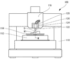
本発明の一実施形態に係る表面形状測定装置100は、図1及び図2に示すように、装置基部110と、装置基部110に固定された水平面移動機構112と、水平面移動機構112によって移動され、被測定物W1を支持するようにされたステージ114と、装置基部110に固定された垂直粗動テーブル116と、垂直粗動テーブル116に保持された表面形状センサユニット120と、を備える。
As shown in FIGS. 1 and 2, the surface
表面形状センサユニット120は、物体表面にレーザー光を照射し、該物体表面からの反射光を受光することにより物体表面の位置を測定する光式の非接触センサ(第1センサ)122と、非接触センサ122を保持する第1駆動部124と、第1駆動部124を保持し、垂直粗動テーブル116に固定された第2駆動部126とを有する。
The surface
非接触センサ122は、鉛直方向に延びる測定軸線Mの方向での物体表面の位置を測定するようにされ、測定軸線Mの方向でおよそ10マイクロメートルの幅がある検出限界を有し、この検出限界の中心位置に設定された測定基準点からの物体表面の相対的距離を測定するようになっている。また、その測定分解能はおよそ10ピコメートルである。なお、測定基準点は、測定軸線M上の任意の位置に設定できる。
The
第1駆動部124は、非接触センサ122を測定軸線Mの方向で移動させるピエゾアクチュエータ(第1アクチュエータ)とピエゾアクチュエータの変位量を測定するひずみセンサ(第2センサ)とを内蔵している。ピエゾアクチュエータは測定軸線Mの方向でおよそ1ミリメートルの幅の可動範囲を有する。また、位置決めの分解能は、およそ20ナノメートルである。従って、第1駆動部124は、非接触センサ122を1ミリメートルの範囲内で20ナノメートルの分解能で位置決めすることができる。
The
第2駆動部126は、第1駆動部124を測定軸線Mの方向で移動させるモータ駆動の直動テーブル(第2アクチュエータ)と直動テーブルの移動距離を測定するリニアスケール(第3センサ)とを有している。直動テーブルは測定軸線Mの方向でおよそ50ミリメートルの幅の可動範囲を有する。また、位置決めの分解能は、およそ50ナノメートルである。したがって、第2駆動部126は、第1駆動部124と第1駆動部124に保持された非接触センサ122とを50ミリメートルの範囲内で50ナノメートルの分解能で位置決めすることができる。
The
図3aに示すような表面を有する被測定物W1の表面形状を当該表面形状測定装置100によって測定する方法について以下に説明する。当該表面形状測定装置100により被測定物W1の表面形状の測定を始めるに際し、まずは、測定対象となる被測定物W1をステージ114上に載置する。次に、水平面移動機構112によってステージ114を水平方向に移動させることにより、被測定物W1上の測定開始点P1が非接触センサ122の測定軸線M上にくるようにして、被測定物W1の測定開始点P1と非接触センサ122の測定点Dとが一致するようにする。また、垂直粗動テーブル116で表面形状センサユニット120を垂直方向に移動させて、測定点Dが非接触センサ122の測定限界内もしくはその近傍にくるようにする。そして、表面形状センサユニット120の第2駆動部126の直動テーブルで非接触センサ122を第1駆動部124とともに移動させて、測定点Dと測定基準点とが一致するようにする。
A method for measuring the surface shape of the workpiece W1 having the surface as shown in FIG. 3a by the surface
次に、水平面移動機構112によりステージ114上に載置された被測定物W1を表面形状センサユニット120に対して水平方向に一定速度で移動させていく。このとき、測定点Dは被測定物W1の表面上を移動していくことになる。非接触センサ122は、ステージ114の移動に同期して測定点Dにおける被測定物W1の表面位置を連続的に測定していく。第1駆動部124のピエゾアクチュエータは、非接触センサ122の出力値に基づき、測定点Dと測定基準点との間に差異がある場合には、測定点Dが測定基準点に近づくように非接触センサ122を移動させる。すなわち、ピエゾアクチュエータは、非接触センサ122と測定表面との間の距離を一定に保つように非接触センサ122を移動させる。このとき第2駆動部126の直動テーブルは移動しない。測定点Dが測定終了点P2にまできたら測定を一旦終了する。
Next, the object to be measured W1 placed on the
表面形状を測定する面の間に第1駆動部124の可動範囲を超える大きさの段差S等がある場合には、一旦表面形状測定を停止し、段差Sを越えた再測定開始点P3の位置において第2駆動部126の直動テーブルで非接触センサ122を第1駆動部124とともに移動させて、測定点Dと測定基準点とが再び一致するように位置合わせをする。その後、上述のように、水平面移動機構112によりステージ114上に載置された被測定物W1を表面形状センサユニット120に対して水平方向に一定速度で移動させながら、再測定開始点P3から再測定終了点P4までの表面形状測定を行う。
If there is a step S having a size exceeding the movable range of the
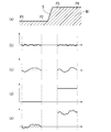
当該表面形状測定装置100で、図3aに示す被測定物W1の表面を測定したときの、非接触センサ122、第1駆動部124のひずみセンサ、及び第2駆動部126のリニアスケールの出力値を図3b-3dにそれぞれ示す。ピエゾアクチュエータは、表面の細かな凹凸に追従できるほどの高速応答性がないので、この凹凸よりも緩やかに変化する表面のうねりに沿って非接触センサ122を移動させるようになる。そのため、非接触センサ122は、表面のうねりは検出せず表面の細かな凹凸情報だけを検出する(図3b)。その一方で、ピエゾアクチュエータの移動距離を測定したひずみセンサは、表面の細かな凹凸形状は検出せず、表面のうねりだけを検出する(図3c)。直動テーブルは、測定開始点P1から測定終了点P2までの表面形状を測定している間は移動しないので、直動テーブルの移動距離を測定するリニアスケールの出力値はこの間は一定となっている(図3d)。測定終了点P2と再測定開始点P3との間には大きな段差Sがあり、この段差Sの前後で、直動テーブルによって非接触センサ122の測定点Dが測定基準点に一致するように非接触センサ122を第1駆動部124とともに移動させているため、再測定開始点P3の位置でリニアスケールの出力値が段差Sの高さ分だけ大きくなっている。再測定開始点P3から再測定終了点P4までの非接触センサ122による出力値には、段差Sの分の高さ変動は現れない(図3b)。同様にひずみセンサの出力値にも段差Sの分の高さ変動は現れない(図3c)。このようにして測定された非接触センサ122、ひずみセンサ、及びリニアスケールの出力値を足し合わせると図3eにようになり、これが被測定物W1の表面形状を測定した結果となる。この測定により、ナノメートルオーダーの測定により表面粗さが求められると同時にミリメートルオーダーの表面の形状も求めることができる。なお、図3の各グラフの縦軸スケールは、各データを強調するためにそれぞれ異なっており、例えば図3bはナノメートルオーダーのスケールであり、図3dはミリメートルオーダーのスケールである。また、図3eは表面形状を強調して表示したものであり、縦軸スケールは一定ではない。さらにステージ114の位置も測定すれば、被測定物W1の各部の板厚を測定することも可能である。
When the surface
上記実施例においては、被測定物W1の表面形状の測定中は、第2駆動部126の直動テーブルは移動させず一定の位置に保持するようにしているが、例えば、被測定物の表面が全体的に傾斜していたり、なだらかに変化していたりするような場合には、測定中に直動テーブルも同時に移動させて表面形状測定を途切れることなく連続的に行うようにすることもできる。ただし、大きな可動範囲の幅を有する直動テーブルは、もともとピエゾアクチュエータほどの高速応答性はなく、また非接触センサ122とピエゾアクチュエータとを合わせた重量を移動させる必要もあるので、図3aに示す段差Sのような急激に形状が変化する部分では通常は追従して移動できない。
In the above embodiment, during the measurement of the surface shape of the object to be measured W1, the linear motion table of the
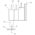
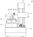
本発明の第2の実施形態に係る表面形状測定装置200は、図4に示すように、装置基部210と、装置基部210に固定された回転機構212と、回転機構212によって回転移動され、被測定物W2を支持するようにされたステージ214と、装置基部210に保持された垂直粗動テーブル216と、垂直粗動テーブル216に保持された径方向粗動テーブル218と、径方向粗動テーブル218に保持された表面形状センサユニット220と、を備える。
As shown in FIG. 4, the surface
表面形状センサユニット220は、上記第1の実施形態に係る表面形状測定装置100の表面形状センサユニット120と同様に、物体表面にレーザー光を照射し、該物体表面からの反射光を受光することにより物体表面の位置を測定する光式の非接触センサ222(第1センサ)と、非接触センサ222を保持する第1駆動部224と、第1駆動部224を保持し、径方向粗動テーブル218に固定された第2駆動部226とを有する。また、第1駆動部224は、非接触センサ222を測定軸線Mの方向で移動させるピエゾアクチュエータ(第1アクチュエータ)とピエゾアクチュエータの変位量を測定するひずみセンサ(第2センサ)とを内蔵し、第2駆動部226は、第1駆動部224を測定軸線Mの方向で移動させる直動テーブル(第2アクチュエータ)と直動テーブルの移動距離を測定するリニアスケール(第3センサ)とを有している。各センサ及びアクチュエータは、第1の実施形態に係る表面形状測定装置100のものと同様である。ただし、当該表面形状測定装置200における表面形状センサユニット220は、その測定軸線Mがステージ214の回転軸線Rに対して垂直な方向、すなわち水平方向となるように取り付けられている。
Similar to the surface
当該表面形状測定装置200が測定の対象とする被測定物W2は、円筒状の外周面や内周面を有する円柱状又は円筒状部材である。当該表面形状測定装置200により被測定物W2の表面形状測定を始めるに際し、まずは、測定対象となる被測定物W2の中心軸線がステージ214の回転軸線Rと一致するようにステージ214上に載置する。次に、垂直粗動テーブル216によって表面形状センサユニット220を垂直方向で移動させることにより、被測定物W2上の測定開始点が非接触センサ222の測定軸線M上にくるようにして、被測定物W2の測定開始点と非接触センサ222の測定点Dとが一致するようにする。また、径方向粗動テーブル218で表面形状センサユニット220を水平方向に移動させて、測定点Dが非接触センサ222の測定限界内又はその近傍にくるようにする。そして、表面形状センサユニット220の第2駆動部226の直動テーブルで非接触センサ222を第1駆動部224とともに移動させて、測定点Dと測定基準点とが一致するようにする。
The workpiece W2 to be measured by the surface
次に、回転機構212によりステージ214上に載置された被測定物W2を表面形状センサユニット220に対して回転軸線Rの周りで一定速度で回転させる。このとき、測定点Dは被測定物W2の円筒状表面上を移動していくことになる。非接触センサ222は、ステージ214の回転に同期して測定点Dにおける被測定物W2の表面位置を連続的に測定していく。第1駆動部224のピエゾアクチュエータは、非接触センサ222の出力値に基づき、測定点Dと測定基準点との間に差異がある場合には、測定点Dが測定基準点に近づくように非接触センサ222を移動させる。すなわち、ピエゾアクチュエータは、非接触センサ222と測定表面との間の距離を一定に保つように非接触センサ222を移動させる。このとき第2駆動部226の直動テーブルは移動しない。測定点Dが円筒状表面上を一周したら測定を終了する。
Next, the workpiece W <b> 2 placed on the
垂直方向の別の位置での円筒状表面の測定をする場合には、次の測定開始点まで垂直粗動テーブル216により表面形状センサユニット220を垂直方向に移動させる。このとき、先に測定した円筒状表面の半径と次に測定する円筒状表面の半径とが異なる場合には、第2駆動部226の直動テーブルで非接触センサ222を第1駆動部224とともに移動させて、測定点Dと測定基準点とが一致するようにするように再度位置合わせをする。その後、上述のように、回転機構212によりステージ214上に載置された被測定物W2を表面形状センサユニット220に対して回転軸線Rの周りで一定速度で回転させながら、表面形状測定を行うようにする。このような測定を行うことにより、各円筒状表面の半径の差異を正確に測定することができる。
When measuring the cylindrical surface at another position in the vertical direction, the surface
当該表面形状測定装置200においては、被測定物W2の測定に先立って、直径が既知の基準ゲージを測定して、ステージ214の回転軸線Rの位置において各センサの出力値がゼロになるように校正をしておくことにより、被測定物W2の円筒状表面の直径を正確に測定することも可能である。また、非接触センサ222のレーザー出射部及び受光部は、下方に細長く延びるように形成されているので、非接触センサ222を円筒状部材の中に挿入して、円筒状部材の内周面の測定をすることも可能である。
In the surface
このように、本発明の表面形状測定装置100,200によれば、ミリメートルオーダーの高低差がある表面の表面形状をナノメートルオーダーの測定分解能で一度に測定することができるので、従来複数の測定装置を必要としていた被測定物の表面形状測定を一つの測定装置で行うことが可能となる。
As described above, according to the surface
上記実施形態において示した表面形状センサユニット120、220の各センサ及びアクチュエータの性能を示す具体的数値は単なる例示であり、それ以外の性能値を有するものでもよいが、例えば、非接触センサ122、222(第1センサ)の検出限界は1マイクロメートル以上0.1ミリメートル未満であるのが好ましく、またその分解能は1ピコメートルから1ナノメートルの範囲内であるのが好ましく、ピエゾアクチュエータ(第1アクチュエータ)の可動範囲は0.1ミリメートル以上2ミリメートル未満であるのが好ましく、直動テーブル(第2アクチュエータ)の可動範囲は10ミリメートル以上300ミリメートル未満であるのが好ましく、ひずみセンサ(第2センサ)の分解能は1ナノメートルから50ナノメートルの範囲内であるのが好ましく、リニアスケール(第3センサ)の分解能は1ナノメートルから100ナノメートルの範囲内であるのが好ましい。
Specific numerical values indicating the performance of the sensors and actuators of the surface
光式の非接触センサ122、222は、上記性能と同程度の性能を有するものであれば、例えば触針式の接触センサのような他のセンサを利用してもよい。また、第1駆動部124、224及び第2駆動部126、226をそれぞれ構成する、ピエゾアクチュエータ、ひずみセンサ、直動テーブル、及びリニアスケールについても、上記性能と同程度の性能を有するものであれば、他のアクチュエータ及びセンサを使用することができる。
The optical
また、上記実施形態においては、非接触センサ122、222が物体表面の一点の高さを測定する点計測センサであるとして説明をしてきたが、検出素子がライン状又は面状に配置されたライン計測センサ又は面計測センサとすることもできる。例えば、ライン計測センサの場合には、一度に物体表面上のライン状の位置での高さを同時に測定することができるが、そのライン状のいずれかの点を上記実施形態における測定点Dとして選択して、当該ライン計測センサの測定軸線Mの方向での位置制御を行うようにすることができる。または、測定中に測定点Dを別のライン状の点に変更するようにしてもよい。これらは面計測センサについても同様である。
In the above-described embodiment, the
表面形状測定装置100;装置基部110;水平面移動機構112;ステージ114;垂直粗動テーブル116;表面形状センサユニット120;非接触センサ(第1センサ)122;第1駆動部124;第2駆動部126;
表面形状測定装置200;装置基部210;回転機構212;ステージ214;垂直粗動テーブル216;径方向粗動テーブル218;表面形状センサユニット220;非接触センサ(第1センサ)222;第1駆動部224;第2駆動部226;
被測定物W1、W2;測定軸線M;測定点D;測定開始点P1:測定終了点P2;再測定開始点P3;再測定終了点P4;段差S;回転軸線R
Surface
Surface
Measurement object W1, W2; measurement axis M; measurement point D; measurement start point P1: measurement end point P2; remeasurement start point P3; remeasurement end point P4;
Claims (11)
該装置基部に設定され、被測定物を支持するステージと、
該装置基部に設定され、該ステージによって支持されている被測定物の表面形状を測定するための表面形状センサユニットと、
該ステージを該表面形状センサユニットに対して相対的に移動させる移動機構と、
を備える表面形状測定装置であって、
該表面形状センサユニットが、
所定の測定軸線の方向での所定幅をもった検出限界を有し、該測定軸線と交わる物体表面上の点を測定点として、該測定軸線の方向での該検出限界内における該測定点の位置を測定する第1センサと、
該第1センサを保持する第1アクチュエータであって、該検出限界の幅よりも広い該測定軸線の方向での所定幅をもった第1可動範囲を有し、該測定点が該検出限界内に位置するように該第1センサを該第1可動範囲内で該測定軸線の方向で移動させる第1アクチュエータと、
該第1アクチュエータによる該第1センサの移動距離を測定する第2センサと、
該第1アクチュエータを保持する第2アクチュエータであって、該第1可動範囲の幅よりも広い該測定軸線の方向での所定幅をもった第2可動範囲を有し、該第1アクチュエータが該第1センサを該第1可動範囲内で移動させて該測定点を該検出限界内に位置させることができるように、該第1アクチュエータを該第2可動範囲内で該測定軸線の方向で移動させる第2アクチュエータと、
該第2アクチュエータによる該第1アクチュエータの移動距離を測定する第3センサと、を備え、
該移動機構によって該第1センサの該測定点が被測定物の表面上を相対的に移動していくように該ステージと該第1センサとを相対的に移動させたときの、該第1、第2、及び第3センサの出力値に基づいて被測定物の表面形状を測定するようにされた、表面形状測定装置。 A device base;
A stage set at the base of the apparatus and supporting the object to be measured;
A surface shape sensor unit for measuring the surface shape of an object to be measured which is set in the apparatus base and supported by the stage;
A moving mechanism for moving the stage relative to the surface shape sensor unit;
A surface shape measuring device comprising:
The surface shape sensor unit is
A detection limit having a predetermined width in the direction of a predetermined measurement axis, and a point on the surface of the object that intersects the measurement axis as a measurement point, the measurement point within the detection limit in the direction of the measurement axis A first sensor for measuring the position;
A first actuator for holding the first sensor, having a first movable range having a predetermined width in the direction of the measurement axis that is wider than the width of the detection limit, and the measurement point is within the detection limit; A first actuator for moving the first sensor in the direction of the measurement axis within the first movable range so as to be positioned at
A second sensor for measuring a moving distance of the first sensor by the first actuator;
A second actuator that holds the first actuator and has a second movable range having a predetermined width in the direction of the measurement axis that is wider than the width of the first movable range; The first actuator is moved in the direction of the measurement axis within the second movable range so that the first sensor can be moved within the first movable range to position the measurement point within the detection limit. A second actuator,
A third sensor for measuring a movement distance of the first actuator by the second actuator,
The first stage when the stage and the first sensor are moved relative to each other so that the measurement point of the first sensor moves relatively on the surface of the object to be measured by the moving mechanism. A surface shape measuring device configured to measure the surface shape of an object to be measured based on output values of the second and third sensors.
該被測定物の表面上の任意の測定開始点に該第1センサの該測定点が位置するように、該ステージと該表面形状センサユニットとを移動機構によって相対的に移動させるステップと、
該測定点が該検出限界内に位置するように、該第2アクチュエータによって該第1アクチュエータ及び該第1センサを該測定軸線の方向で移動させるステップと、
該測定点が該被測定物の表面上を相対的に移動していくように該移動機構によって該ステージと該表面形状センサユニットとを相対的に移動させるステップと、
該ステージと該表面形状センサユニットとを相対的に移動させるステップの最中に、該測定点が該検出限界内に維持されるように該第1アクチュエータによって該第1センサを該測定軸線の方向で移動させるステップと、
該ステージと該表面形状センサユニットとを相対的に移動させるステップの最中に、該第1乃至第3センサの出力値を読み取るステップと、
該測定点を該検出限界内に維持するために必要とされる該第1センサの移動距離が該第1アクチュエータの可動範囲を超えることになる表面を測定するときに、該移動機構による該ステージと該表面形状センサユニットとの相対的な移動を一旦停止して、該測定点が該検出限界内に位置するように該第2アクチュエータによって該第1アクチュエータ及び該第1センサを該測定軸線の方向で移動させるステップと、
を含む、表面形状測定方法。 A first sensor that has a detection limit with a predetermined width in the direction of a predetermined measurement axis, and that measures a position in the direction of the measurement axis of a measurement point that is a point on the object surface that intersects the measurement axis; A first actuator that holds the first sensor and moves the first sensor in the direction of the measurement axis; a second sensor that measures a moving distance of the first sensor by the first actuator; and the first actuator A surface shape sensor unit comprising: a second actuator that moves the first actuator in the direction of the measurement axis while holding the third sensor; and a third sensor that measures a movement distance of the first actuator by the second actuator, A surface shape measuring method for measuring a surface shape of an object supported on a stage,
Relatively moving the stage and the surface shape sensor unit by a moving mechanism so that the measurement point of the first sensor is positioned at an arbitrary measurement start point on the surface of the object to be measured;
Moving the first actuator and the first sensor in the direction of the measurement axis by the second actuator so that the measurement point is within the detection limit;
Relatively moving the stage and the surface shape sensor unit by the moving mechanism so that the measurement point relatively moves on the surface of the object to be measured;
During the step of relatively moving the stage and the surface shape sensor unit, the first actuator moves the first sensor in the direction of the measurement axis so that the measurement point is maintained within the detection limit. Step to move with,
Reading the output values of the first to third sensors during the step of relatively moving the stage and the surface shape sensor unit;
The stage by the moving mechanism when measuring a surface where the moving distance of the first sensor required to maintain the measuring point within the detection limit exceeds the movable range of the first actuator And the surface shape sensor unit are temporarily stopped, and the first actuator and the first sensor are moved along the measurement axis by the second actuator so that the measurement point is located within the detection limit. Moving in the direction,
A surface shape measuring method.
該第1センサを該測定軸線の方向で移動させるステップが、該測定点が該測定基準点に近づくように該第1アクチュエータによって該第1センサを該測定軸線の方向で連続的に移動させるステップである、請求項9に記載の表面形状測定方法。 The first actuator has a measurement reference point located within the detection limit;
The step of moving the first sensor in the direction of the measurement axis includes the step of continuously moving the first sensor in the direction of the measurement axis by the first actuator so that the measurement point approaches the measurement reference point. The surface shape measuring method according to claim 9, wherein
該ステージと該表面形状センサユニットとを相対的に移動させるステップが、該測定点が該被測定物の該円筒状表面上を移動していくように該回転機構によって該ステージを回転させるステップであり、
該第1乃至第3センサの出力値に基づいて、該被測定物の直径と真円度とのうちの少なくとも一方を求めるようにされた、請求項9又は10に記載の表面形状測定方法。 The moving means has a rotation mechanism for rotating the stage around a rotation axis perpendicular to the measurement axis, and a vertical movement mechanism for moving the surface shape sensor unit in a direction parallel to the rotation axis. , The object to be measured is a member having a cylindrical surface,
The step of relatively moving the stage and the surface shape sensor unit is a step of rotating the stage by the rotation mechanism so that the measurement point moves on the cylindrical surface of the object to be measured. Yes,
The surface shape measuring method according to claim 9 or 10, wherein at least one of a diameter and a roundness of the object to be measured is obtained based on output values of the first to third sensors.
Priority Applications (1)
| Application Number | Priority Date | Filing Date | Title |
|---|---|---|---|
| JP2015078282A JP2016200399A (en) | 2015-04-07 | 2015-04-07 | Surface shape measurement device and surface shape measurement method |
Applications Claiming Priority (1)
| Application Number | Priority Date | Filing Date | Title |
|---|---|---|---|
| JP2015078282A JP2016200399A (en) | 2015-04-07 | 2015-04-07 | Surface shape measurement device and surface shape measurement method |
Publications (2)
| Publication Number | Publication Date |
|---|---|
| JP2016200399A true JP2016200399A (en) | 2016-12-01 |
| JP2016200399A5 JP2016200399A5 (en) | 2018-01-11 |
Family
ID=57424133
Family Applications (1)
| Application Number | Title | Priority Date | Filing Date |
|---|---|---|---|
| JP2015078282A Pending JP2016200399A (en) | 2015-04-07 | 2015-04-07 | Surface shape measurement device and surface shape measurement method |
Country Status (1)
| Country | Link |
|---|---|
| JP (1) | JP2016200399A (en) |
Cited By (1)
| Publication number | Priority date | Publication date | Assignee | Title |
|---|---|---|---|---|
| JP2020067443A (en) * | 2018-10-26 | 2020-04-30 | 株式会社ミツトヨ | Shape measurement device and shape measurement method |
Citations (2)
| Publication number | Priority date | Publication date | Assignee | Title |
|---|---|---|---|---|
| JPS6382390A (en) * | 1986-09-26 | 1988-04-13 | 日立電子エンジニアリング株式会社 | Movable stage mechanism |
| JP2003075322A (en) * | 2001-09-07 | 2003-03-12 | Mitsutoyo Corp | Probe |
-
2015
- 2015-04-07 JP JP2015078282A patent/JP2016200399A/en active Pending
Patent Citations (2)
| Publication number | Priority date | Publication date | Assignee | Title |
|---|---|---|---|---|
| JPS6382390A (en) * | 1986-09-26 | 1988-04-13 | 日立電子エンジニアリング株式会社 | Movable stage mechanism |
| JP2003075322A (en) * | 2001-09-07 | 2003-03-12 | Mitsutoyo Corp | Probe |
Cited By (2)
| Publication number | Priority date | Publication date | Assignee | Title |
|---|---|---|---|---|
| JP2020067443A (en) * | 2018-10-26 | 2020-04-30 | 株式会社ミツトヨ | Shape measurement device and shape measurement method |
| JP7198631B2 (en) | 2018-10-26 | 2023-01-04 | 株式会社ミツトヨ | Shape measuring device and shape measuring method |
Similar Documents
| Publication | Publication Date | Title |
|---|---|---|
| JP6208844B2 (en) | Method for determining the shape contour of the measurement object | |
| JP6316858B2 (en) | Automatic measuring device for motor shaft accuracy | |
| JP6608729B2 (en) | Surface texture measuring machine and surface texture measuring method | |
| TW201248118A (en) | Accumulated lead error measurement device of ball screw shaft and measurement method thereof | |
| JP4419481B2 (en) | Method and apparatus for measuring tire shape | |
| JP6417691B2 (en) | Dimension measuring apparatus and dimension measuring method | |
| JP2011127952A (en) | Apparatus for measuring surface texture | |
| JP5847819B2 (en) | Calibration device for measuring gauge of cylinder diameter and other geometric features | |
| JP2017072455A (en) | Measurement probe and measurement probe system | |
| JP6346538B2 (en) | Shape measuring apparatus and shape measuring method | |
| WO2017209026A1 (en) | Shape measuring device and shape measuring method | |
| JP4923441B2 (en) | Shape measuring instrument | |
| JP2016200399A (en) | Surface shape measurement device and surface shape measurement method | |
| Ito et al. | On-machine form measurement of high precision ceramics parts by using a laser displacement sensor | |
| JP4704932B2 (en) | Stylus type shape measuring device and method and rotation restricting air cylinder suitable for the same | |
| WO2015087411A1 (en) | Processing apparatus and processing method | |
| JP2011069680A (en) | Surface roughness measuring device and surface roughness measuring method | |
| JP2006266910A (en) | Measuring method and measuring device for cylindrical shape | |
| JP2000249540A (en) | Device and method for measuring shape of cylindrical object | |
| JP2010271047A (en) | Apparatus for measuring shaft having optical type and touch probe type measuring mechanisms and shaft supporting mechanism, and method for measuring specifications and accuracy of shaft by the apparatus | |
| Ito et al. | Measurement of cutting edge width of a rotary cutting tool by using a laser displacement sensor | |
| KR200450888Y1 (en) | Robber roller supporting device of surface roughness tester | |
| JP2014149247A (en) | Measurement method, determination method, and measurement instrument | |
| JP2008298506A (en) | Shape measuring device | |
| TW201416166A (en) | Method of inspecting workpiece for processing machine and device thereof |
Legal Events
| Date | Code | Title | Description |
|---|---|---|---|
| A521 | Request for written amendment filed |
Free format text: JAPANESE INTERMEDIATE CODE: A523 Effective date: 20171124 |
|
| A621 | Written request for application examination |
Free format text: JAPANESE INTERMEDIATE CODE: A621 Effective date: 20171124 |
|
| A977 | Report on retrieval |
Free format text: JAPANESE INTERMEDIATE CODE: A971007 Effective date: 20181018 |
|
| A131 | Notification of reasons for refusal |
Free format text: JAPANESE INTERMEDIATE CODE: A131 Effective date: 20181113 |
|
| A02 | Decision of refusal |
Free format text: JAPANESE INTERMEDIATE CODE: A02 Effective date: 20190521 |