JP2016200376A - refrigerator - Google Patents

refrigerator Download PDF

Info

Publication number
JP2016200376A
JP2016200376A JP2015082634A JP2015082634A JP2016200376A JP 2016200376 A JP2016200376 A JP 2016200376A JP 2015082634 A JP2015082634 A JP 2015082634A JP 2015082634 A JP2015082634 A JP 2015082634A JP 2016200376 A JP2016200376 A JP 2016200376A
Authority
JP
Japan
Prior art keywords
refrigeration
refrigeration evaporator
evaporator
defrosting
refrigerant
Prior art date
Legal status (The legal status is an assumption and is not a legal conclusion. Google has not performed a legal analysis and makes no representation as to the accuracy of the status listed.)
Pending
Application number
JP2015082634A
Other languages
Japanese (ja)
Inventor
耕世 西村
Kosei Nishimura
耕世 西村
林 秀竹
Hidetake Hayashi
秀竹 林
野口 明裕
Akihiro Noguchi
明裕 野口
Current Assignee (The listed assignees may be inaccurate. Google has not performed a legal analysis and makes no representation or warranty as to the accuracy of the list.)
Toshiba Lifestyle Products and Services Corp
Original Assignee
Toshiba Lifestyle Products and Services Corp
Priority date (The priority date is an assumption and is not a legal conclusion. Google has not performed a legal analysis and makes no representation as to the accuracy of the date listed.)
Filing date
Publication date
Application filed by Toshiba Lifestyle Products and Services Corp filed Critical Toshiba Lifestyle Products and Services Corp
Priority to JP2015082634A priority Critical patent/JP2016200376A/en
Publication of JP2016200376A publication Critical patent/JP2016200376A/en
Pending legal-status Critical Current

Links

Images

Abstract

PROBLEM TO BE SOLVED: To provide a refrigerator that can shorten the time for which the cooling of a refrigerating space is stopping.SOLUTION: A refrigerator includes a cooling cycle in which a compressor 41, a condenser 42 and a selector valve 43 are successively connected, an evaporator 52 for refrigerating is connected to a first outlet of the selector valve, an evaporator 62 for freezing is connected to a second outlet of the selector valve, and the evaporator for refrigerating and the evaporator for freezing are connected to the compressor, a defrosting device 65, and a control portion for controlling the cooling system and the defrosting device. The control portion implements a basic operation control for alternately operating the evaporator for refrigerating and the evaporator for freezing, so that the basic operation control is stopped and the defrost control is executed when a defrost start condition is satisfied, and in the defrost control, the evaporator for freezing is defrosted by the defrosting device after recovering a refrigerant in the evaporator for freezing with the compressor, and the evaporator for refrigerating is operated during the defrosting.SELECTED DRAWING: Figure 2

Description

本発明の実施形態は、冷蔵庫に関する。   Embodiments of the present invention relate to a refrigerator.

冷蔵庫では、圧縮機、凝縮器、蒸発器がこの順に配管等で接続されて、冷媒が循環するループが形成されている。一部の冷蔵庫は、圧縮機及び凝縮器を1つだけ備え、蒸発器を2つ備える。蒸発器の1つは冷蔵冷却用、もう1つは冷凍冷却用である。これらの蒸発器は、前記ループにおいて、並列に設けられている。そして、冷蔵空間を冷却(冷蔵冷却)する場合は冷蔵冷却用の蒸発器の方に冷媒を流し、冷凍空間を冷却(冷凍冷却)する場合は冷凍冷却用蒸発器の方に冷媒を流すように、構成されている(例えば特許文献1参照)。   In a refrigerator, a compressor, a condenser, and an evaporator are connected in this order by piping or the like, and a loop in which the refrigerant circulates is formed. Some refrigerators have only one compressor and condenser, and two evaporators. One of the evaporators is for refrigeration cooling and the other is for refrigeration cooling. These evaporators are provided in parallel in the loop. When the refrigerated space is cooled (refrigerated cooling), the refrigerant flows toward the refrigerated cooling evaporator, and when the refrigerated space is cooled (refrigerated cooling), the refrigerant flows toward the refrigerated cooling evaporator. (See, for example, Patent Document 1).

ところで、一般に冷媒はイソブタン等の可燃性を有する物質であるため、冷凍冷却用蒸発器を加熱する除霜の前に、冷凍冷却用蒸発器から冷媒を抜くいわゆるポンプダウンが行われる。その後、冷凍冷却用蒸発器の除霜が行われるが、除霜中に冷蔵冷却を行うと、ポンプダウンで抜かれた大量の冷媒が冷蔵冷却用蒸発器に流れることになる。すると、冷蔵冷却用蒸発器で冷媒が蒸発しきれず、液体の冷媒が冷蔵冷却用蒸発器から流出し圧縮機に流れ込み、圧縮機が壊れるおそれがある。これを防ぐために、ポンプダウン後の除霜中は、冷凍冷却はもちろんのこと、冷蔵冷却も行われていなかった。   By the way, since the refrigerant is generally a flammable substance such as isobutane, so-called pump-down in which the refrigerant is extracted from the refrigeration / cooling evaporator is performed before defrosting to heat the refrigeration / cooling evaporator. Thereafter, defrosting of the refrigeration / cooling evaporator is performed, but if refrigeration cooling is performed during the defrosting, a large amount of refrigerant extracted by pump-down flows to the refrigeration / cooling evaporator. Then, the refrigerant cannot be completely evaporated by the refrigeration cooling evaporator, and the liquid refrigerant flows out of the refrigeration cooling evaporator and flows into the compressor, and the compressor may be broken. In order to prevent this, not only refrigeration cooling but also refrigeration cooling was not performed during defrosting after pump down.

特開2011−257113号公報JP 2011-257113 A

このように従来は、除霜中に冷蔵冷却が行われないために、冷蔵空間の冷却が止まっている時間が長く、冷蔵空間の温度が上昇し易いという問題があった。   As described above, conventionally, since refrigeration cooling is not performed during defrosting, there is a problem that the cooling time of the refrigeration space is long and the temperature of the refrigeration space easily rises.

そこで本発明では、冷蔵空間の冷却が止まっている時間を短くでき、冷蔵空間の温度上昇を抑えることができる冷蔵庫を提供することを課題とする。   Therefore, an object of the present invention is to provide a refrigerator that can shorten the time during which cooling of the refrigerated space is stopped and can suppress an increase in temperature of the refrigerated space.

実施形態の冷蔵庫は、圧縮機、凝縮器、切替弁の順に接続され、前記切替弁が有する第1出口に冷蔵用蒸発器が接続され、前記切替弁が有する第2出口に冷凍用蒸発器が接続され、前記冷蔵用蒸発器と前記冷凍用蒸発器とが前記圧縮機に接続された冷却サイクルと、前記冷凍用蒸発器の除霜を行う除霜装置と、前記冷却サイクルと前記除霜装置とを制御する制御部とを備え、前記制御部は、前記冷蔵用蒸発器と前記冷凍用蒸発器とを交互に運転する基本運転制御を行うとともに、除霜開始条件が満たされた場合は、前記基本運転制御における前記冷凍用蒸発器の運転後に前記基本運転制御を一時的に停止して除霜用制御を実行し、前記除霜用制御では、前記冷凍用蒸発器内の冷媒を前記圧縮機で回収した後に、前記除霜装置による前記冷凍用蒸発器の除霜を行い、その除霜中に前記冷蔵用蒸発器を運転することを特徴とする。   In the refrigerator of the embodiment, a compressor, a condenser, and a switching valve are connected in this order, a refrigeration evaporator is connected to a first outlet of the switching valve, and a refrigeration evaporator is connected to a second outlet of the switching valve. A cooling cycle in which the refrigeration evaporator and the refrigeration evaporator are connected to the compressor, a defrosting device for defrosting the refrigeration evaporator, the cooling cycle and the defrosting device. A control unit that controls the refrigeration evaporator and the refrigeration evaporator, the control unit performs basic operation control alternately, and when the defrosting start condition is satisfied, After the operation of the refrigeration evaporator in the basic operation control, the basic operation control is temporarily stopped and the defrost control is executed. In the defrost control, the refrigerant in the refrigeration evaporator is compressed. For the freezing by the defroster Performs defrosting of Hatsuki, characterized by operating said refrigerating evaporator during the defrosting.

実施形態の冷蔵庫10の前後方向の断面図。Sectional drawing of the front-back direction of the refrigerator 10 of embodiment. 実施形態の冷却サイクル40を示す図。The figure which shows the cooling cycle 40 of embodiment. 実施形態の冷蔵庫10のブロック図。The block diagram of the refrigerator 10 of embodiment. 実施形態の除霜用制御のフローチャート。The flowchart of the control for defrost of embodiment. 実施形態の別の冷却サイクル140を示す図。The figure which shows another cooling cycle 140 of embodiment. 変更例の冷却サイクル240を示す図。The figure which shows the cooling cycle 240 of the example of a change.

実施形態について図面に基づき説明する。   Embodiments will be described with reference to the drawings.

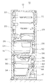
本実施形態に係る冷蔵庫10は、図1に示すように、冷蔵庫10の外郭を形成する外箱と内側に貯蔵空間を形成する内箱とが組み合わさった冷蔵庫本体12を備える。外箱と内箱との間には発泡断熱材等が充填されている。内箱の内側の貯蔵空間は、断熱仕切壁14によって、冷蔵空間20と冷凍空間30とに区画されている。例えば図1の冷蔵庫10の場合は、冷蔵空間20が上側、冷凍空間30が下側になるように区画されている。   As shown in FIG. 1, the refrigerator 10 according to the present embodiment includes a refrigerator main body 12 in which an outer box that forms an outer shell of the refrigerator 10 and an inner box that forms a storage space inside are combined. Between the outer box and the inner box, a foam heat insulating material or the like is filled. The storage space inside the inner box is partitioned into a refrigerated space 20 and a frozen space 30 by a heat insulating partition wall 14. For example, in the case of the refrigerator 10 of FIG. 1, it is partitioned so that the refrigerated space 20 is on the upper side and the refrigerated space 30 is on the lower side.

冷蔵空間20は、冷蔵温度(例えば、2〜3℃)に冷却される空間であって、必要に応じて内部がさらに区画されている。例えば図1の冷蔵庫10の場合は、冷蔵空間20の内部が仕切板によって上下に区画され、上は複数段の載置棚が設けられた冷蔵室22に、下は引き出し式の収納容器24が配置された野菜室26となっている。冷蔵空間20内には、冷蔵空間20内の温度を測定する冷蔵空間用温度センサ29が設けられている。   The refrigeration space 20 is a space that is cooled to a refrigeration temperature (for example, 2 to 3 ° C.), and the inside thereof is further partitioned as necessary. For example, in the case of the refrigerator 10 of FIG. 1, the inside of the refrigeration space 20 is partitioned vertically by a partition plate, the upper part is a refrigeration room 22 provided with a plurality of stages of mounting shelves, and the lower part is a drawer-type storage container 24. It is an arranged vegetable room 26. A refrigerated space temperature sensor 29 that measures the temperature in the refrigerated space 20 is provided in the refrigerated space 20.

冷凍空間30は、冷凍温度(例えば、−18℃以下)に冷却される空間であって、必要に応じて内部がさらに区画されている。例えば図1の冷蔵庫10の場合は、上方に自動製氷機を備えた製氷室32が設けられ、下方に冷凍室34が設けられている。冷凍空間30内には、冷凍空間30内の温度を測定する冷凍空間用温度センサ39が設けられている。   The freezing space 30 is a space cooled to a freezing temperature (for example, −18 ° C. or lower), and the inside thereof is further partitioned as necessary. For example, in the case of the refrigerator 10 of FIG. 1, an ice making chamber 32 provided with an automatic ice maker is provided above, and a freezing chamber 34 is provided below. A frozen space temperature sensor 39 that measures the temperature in the frozen space 30 is provided in the frozen space 30.

冷蔵室22、野菜室26、製氷室32、冷凍室34等の貯蔵室の前方開口部は、それぞれ、観音式や引き出し式等の扉により閉塞されている。   Front openings of storage rooms such as the refrigerator room 22, the vegetable room 26, the ice making room 32, and the freezing room 34 are closed by doors such as a kannon type and a drawer type.

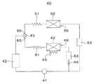
冷蔵空間20及び冷凍空間30を冷却する冷却サイクル40を図2に示す。冷却サイクル40では、圧縮機41と、凝縮器42と、切替弁43が、この順で接続されている。図2の実施形態では、切替弁43は、三方弁となっており、第1出口としての冷蔵側出口50と第2出口としての冷凍側出口60とを有する。   A cooling cycle 40 for cooling the refrigerated space 20 and the frozen space 30 is shown in FIG. In the cooling cycle 40, the compressor 41, the condenser 42, and the switching valve 43 are connected in this order. In the embodiment of FIG. 2, the switching valve 43 is a three-way valve, and has a refrigeration side outlet 50 as a first outlet and a refrigeration side outlet 60 as a second outlet.

冷蔵側出口50には、絞り装置としての冷蔵用キャピラリチューブ51と、冷蔵空間20を冷却するための冷気を発生させる冷蔵用蒸発器52と、気液分離装置としての冷蔵用アキュムレータ53とが、この順で接続されている。冷蔵用アキュムレータ53は、液体の冷媒と気体の冷媒とを分離することができ、さらに液体の冷媒をその内部に貯めることができる。冷蔵用アキュムレータ53は圧縮機41に接続されている。冷蔵用蒸発器52にはその温度を測定する温度センサ56が設けられている。   The refrigerating side outlet 50 includes a refrigerating capillary tube 51 as a throttling device, a refrigerating evaporator 52 that generates cold air for cooling the refrigerating space 20, and a refrigerating accumulator 53 as a gas-liquid separator. They are connected in this order. The refrigeration accumulator 53 can separate the liquid refrigerant and the gaseous refrigerant, and can store the liquid refrigerant therein. The refrigeration accumulator 53 is connected to the compressor 41. The refrigeration evaporator 52 is provided with a temperature sensor 56 for measuring the temperature.

冷凍側出口60には、絞り装置としての冷凍用キャピラリチューブ61と、冷凍空間30を冷却するための冷気を発生させる冷凍用蒸発器62と、気液分離装置としての冷凍用アキュムレータ63と、逆止弁64とが、この順で接続されている。冷凍用アキュムレータ63は、液体の冷媒と気体の冷媒とを分離することができ、さらに液体の冷媒をその内部に貯めることができる。逆止弁64は圧縮機41に接続されている。冷凍用蒸発器62にはその温度を測定する温度センサ66が設けられている。   At the freezing side outlet 60, a freezing capillary tube 61 as a throttling device, a freezing evaporator 62 for generating cold air for cooling the freezing space 30, a freezing accumulator 63 as a gas-liquid separation device, The stop valve 64 is connected in this order. The refrigeration accumulator 63 can separate the liquid refrigerant and the gaseous refrigerant, and can store the liquid refrigerant therein. The check valve 64 is connected to the compressor 41. The refrigeration evaporator 62 is provided with a temperature sensor 66 for measuring the temperature.

以上の構成の冷却サイクル40を冷媒が流れることにより、冷蔵用蒸発器52や冷凍用蒸発器62で冷気が発生する。なお、絞り装置として、キャピラリチューブの代わりに膨張弁が用いられても良い。   When the refrigerant flows through the cooling cycle 40 having the above configuration, cold air is generated in the refrigeration evaporator 52 and the refrigeration evaporator 62. Note that an expansion valve may be used as the throttle device instead of the capillary tube.

冷蔵用蒸発器52は冷蔵空間20の奥に設けられている。冷蔵用蒸発器52の付近には冷蔵用ファン28が設けられている。冷蔵用ファン28が回転すると、冷蔵用蒸発器52の周りを含む冷蔵空間20内全体に冷気が循環する。   The refrigeration evaporator 52 is provided in the back of the refrigeration space 20. A refrigeration fan 28 is provided in the vicinity of the refrigeration evaporator 52. When the refrigeration fan 28 rotates, cold air circulates in the entire refrigeration space 20 including the periphery of the refrigeration evaporator 52.

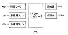
冷凍用蒸発器62は冷凍空間30の奥に設けられている。冷凍用蒸発器62の付近には冷凍用ファン38が設けられている。冷凍用ファン38が回転すると、冷凍用蒸発器62の周りを含む冷凍空間30内全体に冷気が循環する。冷凍用蒸発器62の外側には除霜装置としての除霜ヒータ65が設けられている。   The refrigeration evaporator 62 is provided in the back of the refrigeration space 30. A refrigeration fan 38 is provided in the vicinity of the refrigeration evaporator 62. When the refrigeration fan 38 rotates, cold air circulates throughout the refrigeration space 30 including the refrigeration evaporator 62. A defrosting heater 65 as a defrosting device is provided outside the freezing evaporator 62.

冷蔵庫10には制御部としてのマイクロコンピュータ70が設けられている。図3に示すように、マイクロコンピュータ70には、除霜ヒータ65、冷蔵用ファン28、冷凍用ファン38、冷却サイクル40の圧縮機41、切替弁43、その他必要に応じて各種センサや機器等が接続されている。マイクロコンピュータ70は、接続されているこれらの物を制御する。   The refrigerator 10 is provided with a microcomputer 70 as a control unit. As shown in FIG. 3, the microcomputer 70 includes a defrost heater 65, a refrigeration fan 28, a refrigeration fan 38, a compressor 41 of a cooling cycle 40, a switching valve 43, and other various sensors and devices as necessary. Is connected. The microcomputer 70 controls these connected items.

冷蔵空間20を冷却(冷蔵冷却)する場合、マイクロコンピュータ70は、切替弁43の冷凍側出口60を閉めて冷蔵側出口50を開けることにより、冷媒を冷蔵用蒸発器52へ流し冷蔵用蒸発器52を運転する。また、マイクロコンピュータ70は冷蔵用ファン28を回転させる。これらの制御の結果、冷蔵用蒸発器52の周辺で冷気が発生し、その冷気が冷蔵用ファン28により冷蔵空間20内で循環し、冷蔵空間20が冷蔵温度に冷却される。   When cooling the refrigerated space 20 (refrigerated cooling), the microcomputer 70 closes the refrigeration side outlet 60 of the switching valve 43 and opens the refrigeration side outlet 50, thereby causing the refrigerant to flow to the refrigeration evaporator 52, thereby causing the refrigeration evaporator. Drive 52. Further, the microcomputer 70 rotates the refrigeration fan 28. As a result of these controls, cold air is generated around the refrigeration evaporator 52, and the cold air is circulated in the refrigeration space 20 by the refrigeration fan 28, whereby the refrigeration space 20 is cooled to the refrigeration temperature.

また、冷凍空間30を冷却(冷凍冷却)する場合、マイクロコンピュータ70は、切替弁43の冷蔵側出口50を閉めて冷凍側出口60を開けることにより、冷媒を冷凍用蒸発器62へ流し冷凍用蒸発器62を運転する。また、マイクロコンピュータ70は冷凍用ファン38を回転させる。これらの制御の結果、冷凍用蒸発器62の周辺で冷気が発生し、その冷気が冷凍用ファン38により冷凍空間30内で循環し、冷凍空間30が冷凍温度に冷却される。   When the refrigeration space 30 is cooled (refrigeration cooling), the microcomputer 70 closes the refrigeration side outlet 50 of the switching valve 43 and opens the refrigeration side outlet 60, thereby causing the refrigerant to flow to the refrigeration evaporator 62. The evaporator 62 is operated. Further, the microcomputer 70 rotates the refrigeration fan 38. As a result of these controls, cold air is generated around the freezing evaporator 62, and the cold air is circulated in the freezing space 30 by the freezing fan 38, and the freezing space 30 is cooled to the freezing temperature.

また、冷凍用蒸発器62の除霜を行う場合、マイクロコンピュータ70は、除霜ヒータ65を通電状態にしてこれを暖め、冷凍用蒸発器62に付いた霜を溶かす。なお、除霜により霜が溶けて生じた水は、冷凍用蒸発器62の下に設けられた樋等により回収される。   When defrosting the refrigeration evaporator 62, the microcomputer 70 energizes the defrost heater 65 to warm it and melt the frost attached to the refrigeration evaporator 62. In addition, the water generated when the frost is melted by the defrosting is collected by a basket or the like provided under the freezing evaporator 62.

また、冷凍用蒸発器62から冷媒を抜くいわゆるポンプダウンを行う場合、マイクロコンピュータ70は、切替弁43の冷蔵側出口50と冷凍側出口60とを閉め、圧縮機41を作動させ、冷媒を冷凍用蒸発器62から圧縮機41側へ移動させる。   Further, when performing so-called pump-down in which the refrigerant is extracted from the refrigeration evaporator 62, the microcomputer 70 closes the refrigeration side outlet 50 and the refrigeration side outlet 60 of the switching valve 43, operates the compressor 41, and freezes the refrigerant. It moves from the evaporator 62 to the compressor 41 side.

マイクロコンピュータ70は、冷蔵冷却と冷凍冷却とを交互に実行する基本運転制御を行う。基本運転制御においては、通常、冷凍冷却が終わると、ポンプダウンが行われて冷蔵冷却に必要な冷媒が冷凍用蒸発器62から抜かれ、その後冷蔵冷却が行われる。冷蔵冷却に必要な冷媒の量は、冷凍冷却に必要な冷媒の量よりも少量であるため、基本運転制御における冷蔵冷却前のポンプダウンの実施時間は短時間で良い。   The microcomputer 70 performs basic operation control that alternately executes refrigeration cooling and refrigeration cooling. In the basic operation control, normally, when the refrigeration cooling is finished, the pump down is performed, the refrigerant necessary for the refrigeration cooling is extracted from the refrigeration evaporator 62, and then the refrigeration cooling is performed. Since the amount of refrigerant necessary for refrigeration cooling is smaller than the amount of refrigerant necessary for refrigeration cooling, the pump down time before refrigeration cooling in the basic operation control may be short.

基本運転制御の途中で所定の除霜開始条件が満たされると、マイクロコンピュータ70は、基本運転制御を一時的に停止して、その停止している間に除霜用制御を実行する。除霜開始条件とは、その条件が満たされた場合は除霜が行われるべきであるとして予め定められている条件である。除霜開始条件の内容は限定されない。例えば、冷凍空間30が所定の温度以下になった時や、前回の除霜の完了時から一定時間経過した時や、冷凍冷却の積算時間が一定時間に達した時に、マイクロコンピュータ70が、除霜開始条件が満たされたと判断する。なお、除霜用制御中に冷凍空間30内の温度が上がり過ぎないようにするため、基本運転制御における冷凍冷却の後に除霜用制御が実行される。基本運転制御の冷凍冷却中に除霜開始条件が満たされた場合は、そのまま除霜用制御に移行する。冷凍冷却中を除く時に除霜開始条件が満たされた場合は、その後の冷凍冷却の後に、除霜用制御に移行する。   When a predetermined defrosting start condition is satisfied during the basic operation control, the microcomputer 70 temporarily stops the basic operation control and executes the defrosting control while the basic operation control is stopped. The defrosting start condition is a condition that is determined in advance as that defrosting should be performed when the condition is satisfied. The content of the defrosting start condition is not limited. For example, when the freezing space 30 becomes a predetermined temperature or lower, when a certain time has elapsed since the completion of the previous defrosting, or when the total time for freezing and cooling reaches a certain time, the microcomputer 70 It is determined that the frost start condition is satisfied. In order to prevent the temperature in the refrigeration space 30 from rising excessively during the defrosting control, the defrosting control is executed after the refrigeration cooling in the basic operation control. When the defrosting start condition is satisfied during the refrigeration cooling in the basic operation control, the process proceeds to the defrosting control as it is. When the defrosting start condition is satisfied when the cooling is not performed, the process moves to the defrosting control after the subsequent cooling and cooling.

除霜用制御のフローチャートを図4に示す。除霜用制御が開始される(S1)と、マイクロコンピュータ70は、ポンプダウンを開始して(S2)冷凍用蒸発器62から冷媒を抜く。そして、ポンプダウン終了条件が満たされる(S3のYes)と、マイクロコンピュータ70はポンプダウンを終了する(S4)。マイクロコンピュータ70は、例えば、ポンプダウン開始時から予め設定された一定時間経過した時や、ポンプダウン開始時から圧縮機41の回転数に係数を乗じた時間だけ経過した時等に、ポンプダウン終了条件が満たされたと判断する。その後、マイクロコンピュータ70は、除霜ヒータ65を通電状態にし、冷凍用蒸発器62の除霜を開始する(S5)。   A flowchart of the defrosting control is shown in FIG. When the defrosting control is started (S1), the microcomputer 70 starts pumping down (S2) and removes the refrigerant from the refrigeration evaporator 62. When the pump-down end condition is satisfied (Yes in S3), the microcomputer 70 ends the pump-down (S4). The microcomputer 70 terminates the pump down when, for example, a preset time period has elapsed since the start of the pump down, or when the time obtained by multiplying the rotation speed of the compressor 41 by a coefficient has elapsed since the start of the pump down. Judge that the condition is satisfied. Thereafter, the microcomputer 70 energizes the defrosting heater 65 and starts defrosting the freezing evaporator 62 (S5).

マイクロコンピュータ70は、除霜用制御の一部として、冷凍用蒸発器62の除霜中に、冷蔵冷却を行う。この冷凍用蒸発器62の除霜中の冷蔵冷却は、除霜が開始されると同時に、又は、除霜開始後一定時間経過後に、開始される(S6)。   The microcomputer 70 performs refrigeration cooling during the defrosting of the freezing evaporator 62 as a part of the defrosting control. The refrigeration cooling during the defrosting of the refrigeration evaporator 62 is started simultaneously with the start of the defrosting or after a certain time has elapsed after the start of the defrosting (S6).

冷凍用蒸発器62の除霜中の冷蔵冷却は、冷蔵用蒸発器52を流れる冷媒の量を、基本運転制御における冷蔵冷却中の量と同等か、基本運転制御における冷蔵冷却中の量よりも少なくして行われる。その方法は限定されないが、ここでは3つの方法を例として挙げる。   In the refrigeration cooling during the defrosting of the refrigeration evaporator 62, the amount of the refrigerant flowing through the refrigeration evaporator 52 is equal to the amount during the refrigeration cooling in the basic operation control or more than the amount during the refrigeration cooling in the basic operation control. Done less. Although the method is not limited, three methods will be exemplified here.

1つ目の方法は、冷媒の流れの冷蔵用蒸発器52より上流側に設けられた可変バルブの開度を小さくする方法である。具体的には、マイクロコンピュータ70は、冷凍用蒸発器62の除霜中の冷蔵冷却中は、基本運転制御における冷蔵冷却中よりも、可変バルブの開度を小さくする。切替弁43がこのような可変バルブとして機能しても良い。切替弁43から冷蔵用蒸発器52までの間に切替弁43とは別の可変バルブが設けられ、当該別の可変バルブが冷蔵用蒸発器52へ流れる冷媒の量を変化させても良い。   The first method is a method of reducing the opening degree of the variable valve provided upstream of the refrigeration evaporator 52 in the refrigerant flow. Specifically, the microcomputer 70 makes the opening of the variable valve smaller during refrigeration cooling during defrosting of the refrigeration evaporator 62 than during refrigeration cooling in the basic operation control. The switching valve 43 may function as such a variable valve. A variable valve different from the switching valve 43 may be provided between the switching valve 43 and the refrigeration evaporator 52, and the other variable valve may change the amount of refrigerant flowing to the refrigeration evaporator 52.

2つ目の方法を実施するための冷却サイクル140を図5に示す。図5の冷却サイクル140は、切替弁143と冷蔵用蒸発器52との間に2つの冷蔵用キャピラリチューブ151a、151bが並列に設けられている点で、図2の冷却サイクル40と異なる。なお、図5において、図2の冷却サイクル40に用いられているものと同じ機器等には、図2における符号と同じ符号が付されている。2つの冷蔵用キャピラリチューブ151a、151bは、絞りの大きさが異なる。一方の冷蔵用キャピラリチューブ151aは絞りが小さく、その中を多くの冷媒が通過できる。他方の冷蔵用キャピラリチューブ151bは前記冷蔵用キャピラリチューブ151aよりも絞りが大きく、前記冷蔵用キャピラリチューブ151aと比較してその中を通過できる冷媒が少ない。このような絞りの大きさの違いは、冷蔵用キャピラリチューブの径の大きさ又は長さの違いから生じる。冷蔵用キャピラリチューブの径が小さいほど絞りが大きい。また、冷蔵用キャピラリチューブの長さが長いほど絞りが大きい。図5の冷却サイクル140では、切替弁143は、2つの冷蔵側出口150a、150bを有し、一方の冷蔵側出口150aが一方の冷蔵用キャピラリチューブ151aに、他方の冷蔵側出口150bが他方の冷蔵用キャピラリチューブ151bに、それぞれ接続されている。そして、マイクロコンピュータ70は、冷蔵用蒸発器52に冷媒を流す場合は、切替弁143を切り替えることにより、2つの冷蔵用キャピラリチューブ151a、151bのうちいずれか一方を流路として選択できるようになっている。   A cooling cycle 140 for carrying out the second method is shown in FIG. The cooling cycle 140 in FIG. 5 differs from the cooling cycle 40 in FIG. 2 in that two refrigeration capillary tubes 151 a and 151 b are provided in parallel between the switching valve 143 and the refrigeration evaporator 52. In FIG. 5, the same devices as those used in the cooling cycle 40 of FIG. 2 are denoted by the same reference numerals as those in FIG. 2. The two chilled capillary tubes 151a and 151b have different aperture sizes. One refrigeration capillary tube 151a has a small throttle and allows a large amount of refrigerant to pass therethrough. The other refrigeration capillary tube 151b has a larger throttle than the refrigeration capillary tube 151a, and less refrigerant can pass through the refrigeration capillary tube 151a than the refrigeration capillary tube 151a. Such a difference in the size of the restriction is caused by a difference in the diameter or length of the capillary tube for refrigeration. The smaller the diameter of the refrigerated capillary tube, the larger the restriction. In addition, the longer the length of the chilled capillary tube, the larger the aperture. In the cooling cycle 140 of FIG. 5, the switching valve 143 has two refrigeration side outlets 150a and 150b, one refrigeration side outlet 150a is connected to one refrigeration capillary tube 151a, and the other refrigeration side outlet 150b is connected to the other. Each is connected to the refrigeration capillary tube 151b. The microcomputer 70 can select either one of the two refrigeration capillary tubes 151a and 151b as a flow path by switching the switching valve 143 when the refrigerant is allowed to flow to the refrigeration evaporator 52. ing.

ただし、切替弁が冷蔵用蒸発器52側の出口を1つだけ有する図2の切替弁43と同じものであり、その切替弁43の冷蔵用蒸発器52側の出口と2つの冷蔵用キャピラリチューブ151a、151bとの間に別の切替弁が設けられていても良い。そして、当該別の切替弁により、2つの冷蔵用キャピラリチューブ151a、151bのうちいずれか一方に冷媒を流すように、冷媒の流路の切り替えがなされても良い。また絞り量の異なる冷蔵用キャピラリチューブが3本以上設けられていても良い。その場合、マイクロコンピュータ70は、冷凍用蒸発器62の除霜中の冷蔵冷却中、基本運転制御における冷蔵用蒸発器52の運転中に冷媒を流すキャピラリチューブよりも絞りの大きいキャピラリチューブに冷媒を流す。   However, the switching valve is the same as the switching valve 43 in FIG. 2 having only one outlet on the refrigeration evaporator 52 side, the outlet on the refrigeration evaporator 52 side of the switching valve 43 and two refrigeration capillary tubes. Another switching valve may be provided between 151a and 151b. And the flow path of a refrigerant | coolant may be made | formed so that a refrigerant | coolant may be flowed through either one of the two refrigeration capillary tubes 151a and 151b with the said another switching valve. Further, three or more refrigeration capillary tubes having different squeezing amounts may be provided. In that case, during the refrigeration cooling during the defrosting of the refrigeration evaporator 62, the microcomputer 70 supplies the refrigerant to the capillary tube having a larger throttle than the capillary tube through which the refrigerant flows during the operation of the refrigeration evaporator 52 in the basic operation control. Shed.

以上の構成の冷却サイクル140において、基本運転制御における冷蔵冷却を行う場合は、マイクロコンピュータ70は、絞りが小さい方の冷蔵用キャピラリチューブ151aに冷媒を流す。一方、冷凍用蒸発器62の除霜中に冷蔵冷却を実行する場合は、マイクロコンピュータ70は、絞りが大きい方の冷蔵用キャピラリチューブ151bに冷媒を流す。   In the cooling cycle 140 having the above-described configuration, when performing refrigeration cooling in the basic operation control, the microcomputer 70 causes the refrigerant to flow through the refrigeration capillary tube 151a having the smaller throttle. On the other hand, when performing refrigeration cooling during defrosting of the refrigeration evaporator 62, the microcomputer 70 causes the refrigerant to flow through the refrigeration capillary tube 151b having the larger throttle.

3つ目の方法は、冷凍用蒸発器62の除霜中の冷蔵冷却中に、マイクロコンピュータ70が、圧縮機41の回転数を低下させる方法である。この場合、例えば、冷凍用蒸発器62の除霜中の冷蔵冷却中の圧縮機41の回転数は、基本運転制御における冷蔵冷却中の回転数の半分とする。   The third method is a method in which the microcomputer 70 reduces the rotational speed of the compressor 41 during refrigeration cooling during defrosting of the refrigeration evaporator 62. In this case, for example, the rotation speed of the compressor 41 during refrigeration cooling during defrosting of the refrigeration evaporator 62 is half of the rotation speed during refrigeration cooling in the basic operation control.

冷凍用蒸発器62の除霜中の冷蔵冷却中は、マイクロコンピュータ70は、基本運転制御における冷蔵冷却の実行中よりも、冷蔵用ファン28の回転数を大きくすることが望ましい。   During the refrigeration cooling during the defrosting of the refrigeration evaporator 62, it is desirable that the microcomputer 70 increases the rotational speed of the refrigeration fan 28 than during the execution of the refrigeration cooling in the basic operation control.

冷凍用蒸発器62の除霜中の冷蔵冷却が実行されている間、冷蔵空間用温度センサ29により、冷蔵空間20内の温度が測定されている。冷蔵空間20内の温度が予め設定された目標温度より低くなると(S7のYes)、除霜中であっても、冷蔵冷却が終了される(S8)。冷蔵冷却終了後も、除霜終了条件が満たされるまで除霜が継続され、除霜終了条件が満たされる(S9のYes)と除霜が終わる(S10)。除霜が終わると除霜用制御が終わる(S11)。一方、冷蔵空間20内の温度が予め設定された目標温度以上である(S7のNo)間は、除霜終了条件が満たされない(S12のNo)限り、冷蔵冷却が継続される。しかし、冷蔵空間20内の温度が予め設定された目標温度以上であっても(S7のNo)、除霜終了条件が満たされた場合(S12のYes)は、冷蔵冷却が終わり(S13)、除霜も終わる(S14)。除霜が終わると除霜用制御が終わる(S11)。図4のフローチャートでは、冷蔵冷却が終わった後に除霜が終わるが、終わる順序はこの逆であっても良い。また、冷蔵冷却の終了と除霜の終了とは、同時に行われても良い。なお、除霜終了条件の詳細な内容は限定されない。例えば、冷凍用蒸発器62の温度を測定する温度センサ66により測定される温度が、予め設定された温度以上となった時に、マイクロコンピュータ70は除霜終了条件が満たされたと判断する。   While the refrigeration cooling during the defrosting of the refrigeration evaporator 62 is being performed, the temperature in the refrigerated space 20 is measured by the refrigerated space temperature sensor 29. When the temperature in the refrigerated space 20 becomes lower than the preset target temperature (Yes in S7), the refrigeration cooling is finished even during defrosting (S8). Even after the end of the refrigeration cooling, the defrosting is continued until the defrosting end condition is satisfied. When the defrosting end condition is satisfied (Yes in S9), the defrosting ends (S10). When the defrosting is finished, the defrosting control is finished (S11). On the other hand, while the temperature in the refrigerated space 20 is equal to or higher than a preset target temperature (No in S7), the refrigeration cooling is continued as long as the defrosting termination condition is not satisfied (No in S12). However, even if the temperature in the refrigerated space 20 is equal to or higher than the preset target temperature (No in S7), if the defrosting end condition is satisfied (Yes in S12), the refrigeration cooling ends (S13), Defrosting ends (S14). When the defrosting is finished, the defrosting control is finished (S11). In the flowchart of FIG. 4, the defrosting is finished after the refrigeration cooling is finished, but the order of finishing may be reversed. Moreover, the completion | finish of refrigeration cooling and the completion | finish of a defrost may be performed simultaneously. In addition, the detailed content of the defrost termination conditions is not limited. For example, when the temperature measured by the temperature sensor 66 that measures the temperature of the refrigeration evaporator 62 is equal to or higher than a preset temperature, the microcomputer 70 determines that the defrosting termination condition is satisfied.

除霜用制御が終了した後、マイクロコンピュータ70は、基本運転制御を開始する。冷凍用蒸発器62の除霜によって冷凍用蒸発器62の温度が上昇するため、冷凍用蒸発器62の温度を下げるために、除霜用制御終了後の基本運転制御は冷凍冷却から始まる。   After the defrosting control is completed, the microcomputer 70 starts basic operation control. Since the temperature of the refrigeration evaporator 62 rises due to the defrosting of the refrigeration evaporator 62, the basic operation control after the completion of the defrost control starts with refrigeration cooling in order to lower the temperature of the refrigeration evaporator 62.

なお、上記の除霜用制御において行われる冷凍用蒸発器62の除霜とは別に、所定の条件が満たされた場合に、冷蔵用蒸発器52の除霜も行われる。   In addition to the defrosting of the refrigerating evaporator 62 performed in the defrosting control, the defrosting of the refrigerating evaporator 52 is also performed when a predetermined condition is satisfied.

以上の実施形態の効果は次の通りである。   The effect of the above embodiment is as follows.

以上の実施形態では、冷凍用蒸発器62の除霜中も冷蔵用蒸発器52が運転されるため、冷蔵冷却が止まっている時間が短くなり、冷蔵空間20の温度上昇が抑えられる。   In the above embodiment, since the refrigeration evaporator 52 is operated even during the defrosting of the refrigeration evaporator 62, the time during which the refrigeration cooling stops is shortened, and the temperature rise of the refrigeration space 20 is suppressed.

また、上記のように、冷凍用蒸発器62の除霜前に、冷凍用蒸発器62の冷媒を圧縮機41に回収するポンプダウンが実施される。このポンプダウンにより回収される冷媒は大量であるため、回収された冷媒がそのまま冷蔵用蒸発器52に流れると、冷蔵用蒸発器52で冷媒が蒸発しきれず、また冷蔵用アキュムレータ53が液体の冷媒を回収しきれず、液体の冷媒が圧縮機41に流れ込み、圧縮機41が壊れるおそれがある。しかし、上記実施形態では、マイクロコンピュータ70は、冷凍用蒸発器62の除霜中の冷蔵冷却中に冷蔵用蒸発器52に流れる冷媒の量を、基本運転制御における冷蔵冷却中に冷蔵用蒸発器52に流れる冷媒の量と同等にするか、それより少なくする。そのため、冷蔵用蒸発器52に流れ込んだ液体の冷媒が冷蔵用蒸発器52で蒸発しきれずに圧縮機41に流れ込むことを防ぐことができ、圧縮機41が壊れることを防ぐことができる。   Further, as described above, before the refrigeration evaporator 62 is defrosted, the pump down for recovering the refrigerant of the refrigeration evaporator 62 to the compressor 41 is performed. Since a large amount of refrigerant is recovered by this pump-down, when the recovered refrigerant flows into the refrigeration evaporator 52 as it is, the refrigerant cannot be completely evaporated by the refrigeration evaporator 52 and the refrigeration accumulator 53 is a liquid refrigerant. The liquid refrigerant flows into the compressor 41 and the compressor 41 may be broken. However, in the above embodiment, the microcomputer 70 uses the amount of the refrigerant flowing to the refrigeration evaporator 52 during the refrigeration cooling during the defrosting of the refrigeration evaporator 62, and the refrigeration evaporator during the refrigeration cooling in the basic operation control. The amount of refrigerant flowing to 52 is equal to or less than that. Therefore, the liquid refrigerant flowing into the refrigeration evaporator 52 can be prevented from flowing into the compressor 41 without being completely evaporated by the refrigeration evaporator 52, and the compressor 41 can be prevented from being broken.

また、上記実施形態の場合、冷蔵用蒸発器52と圧縮機41との間に気液分離装置としての冷蔵用アキュムレータ53が接続され、冷蔵用アキュムレータ53で液体の冷媒が回収される。そのため、仮に、マイクロコンピュータ70が冷凍用蒸発器62の除霜中の冷蔵冷却中に冷蔵用蒸発器52に流れる冷媒を少なくしたにもかかわらず、冷蔵用蒸発器52から液体の冷媒が流出したとしても、液体の冷媒が冷蔵用アキュムレータ53より下流の圧縮機41に流れ込むことを防ぐことができ、圧縮機41が壊れることを防ぐことができる。   In the case of the above embodiment, a refrigeration accumulator 53 as a gas-liquid separator is connected between the refrigeration evaporator 52 and the compressor 41, and the liquid refrigerant is recovered by the refrigeration accumulator 53. Therefore, even if the microcomputer 70 reduces the amount of refrigerant flowing into the refrigeration evaporator 52 during refrigeration cooling during the defrosting of the refrigeration evaporator 62, the liquid refrigerant flows out of the refrigeration evaporator 52. However, it is possible to prevent the liquid refrigerant from flowing into the compressor 41 downstream of the refrigeration accumulator 53, and to prevent the compressor 41 from being broken.

また、冷凍用蒸発器62の除霜中の冷蔵冷却中に、基本運転制御における冷蔵冷却中よりも冷蔵用ファン28の回転数が大きくなる場合、冷蔵用蒸発器52での熱交換効率が良くなり、冷蔵用蒸発器52で多くの冷媒が蒸発することになる。そのため、冷蔵用蒸発器52から液体の冷媒が流出しにくくなり、液体の冷媒が圧縮機41に流れ込むことを防ぐことができ、圧縮機41が壊れることを防ぐことができる。   Further, when the number of rotations of the refrigeration fan 28 is larger during refrigeration cooling during defrosting of the refrigeration evaporator 62 than during refrigeration cooling in the basic operation control, the heat exchange efficiency in the refrigeration evaporator 52 is improved. Thus, a large amount of refrigerant evaporates in the refrigeration evaporator 52. Therefore, it becomes difficult for the liquid refrigerant to flow out of the refrigeration evaporator 52, the liquid refrigerant can be prevented from flowing into the compressor 41, and the compressor 41 can be prevented from being broken.

また、冷蔵空間20内の温度が予め設定された目標温度より低くなると、冷凍用蒸発器62の除霜中であっても冷蔵冷却が終了されるため、冷蔵空間20内の温度が下がりすぎることを防ぐことができる。   Further, when the temperature in the refrigerated space 20 becomes lower than a preset target temperature, the refrigerated cooling is terminated even during the defrosting of the refrigeration evaporator 62, and therefore the temperature in the refrigerated space 20 is too low. Can be prevented.

上記実施形態の変更例について説明する。   A modification of the above embodiment will be described.

変更例の1つとして、冷蔵用アキュムレータ53で回収された液体の冷媒が冷却サイクル内の他の部分に回されて、冷却サイクル内で再利用される例が挙げられる。そのような変更例の1つを図6に示す。図6の冷却サイクル240の構造は、図2の実施形態の冷却サイクル40の構造と、基本的には同じである。ただし、図6の冷却サイクル240では、冷蔵用キャピラリチューブ51と冷蔵用蒸発器52との間の部分と、冷蔵用アキュムレータ53とを結ぶ配管254が設けられている。そして、冷蔵用アキュムレータ53で回収された液体の冷媒が、冷蔵用蒸発器52より冷媒の流れの上流側の部分に戻されるように構成されている。この構成の冷却サイクル240では、回収された液体の冷媒が、冷却サイクル240内で再利用されるため、無駄にならない。なお、図6において、図2の冷却サイクル40に用いられているものと同じ機器等には、図2における符号と同じ符号が付されている。   As one example of the change, there is an example in which the liquid refrigerant recovered by the refrigeration accumulator 53 is routed to another part in the cooling cycle and reused in the cooling cycle. One such modification is shown in FIG. The structure of the cooling cycle 240 of FIG. 6 is basically the same as the structure of the cooling cycle 40 of the embodiment of FIG. However, in the cooling cycle 240 of FIG. 6, a pipe 254 that connects a portion between the refrigeration capillary tube 51 and the refrigeration evaporator 52 and the refrigeration accumulator 53 is provided. The liquid refrigerant recovered by the refrigeration accumulator 53 is configured to be returned to the upstream portion of the refrigerant flow from the refrigeration evaporator 52. In the cooling cycle 240 having this configuration, the recovered liquid refrigerant is reused in the cooling cycle 240, so that it is not wasted. In FIG. 6, the same reference numerals as those in FIG. 2 are assigned to the same devices and the like used in the cooling cycle 40 in FIG. 2.

別の変更例について説明する。上記実施形態では、冷凍用蒸発器62の除霜中に冷蔵冷却が行われる場合は、常に、冷蔵用蒸発器52に流れる冷媒の量が、基本運転制御における冷蔵冷却中の量と同等又はこれより少なくなるように制御される。しかし、マイクロコンピュータ70は、冷凍用蒸発器62の除霜中に冷蔵冷却が行われることに加えて、さらに別の条件も満たされた場合に限り、冷蔵用蒸発器52に流れる冷媒が少なくなるように制御しても良い。   Another modification will be described. In the above embodiment, when refrigeration cooling is performed during defrosting of the refrigeration evaporator 62, the amount of refrigerant flowing to the refrigeration evaporator 52 is always equal to or equal to the amount during refrigeration cooling in the basic operation control. Controlled to be less. However, the microcomputer 70 reduces the amount of refrigerant flowing to the refrigeration evaporator 52 only when other conditions are satisfied in addition to the refrigeration cooling being performed during the defrosting of the refrigeration evaporator 62. You may control as follows.

例えば、冷蔵用アキュムレータ53に液体の冷媒が流入したことを検出するセンサが設けられていても良い。そして、マイクロコンピュータ70は、冷凍用蒸発器62の除霜中に冷蔵冷却が行われている状況下であって、かつこのセンサが冷蔵用アキュムレータ53に液体の冷媒が流入したことを検出した場合に、その検出前よりも冷蔵用蒸発器52に流れる冷媒を少なくしても良い。冷蔵用蒸発器52に流れる冷媒を少なくする方法は上記実施形態の通りである。   For example, a sensor that detects that a liquid refrigerant has flowed into the refrigeration accumulator 53 may be provided. The microcomputer 70 is in a state where refrigeration cooling is performed during the defrosting of the refrigeration evaporator 62 and the sensor detects that liquid refrigerant has flowed into the refrigeration accumulator 53. In addition, the refrigerant flowing through the refrigeration evaporator 52 may be less than before the detection. The method of reducing the refrigerant flowing through the refrigeration evaporator 52 is as described in the above embodiment.

この変更例において、冷蔵用アキュムレータ53に液体の冷媒が流入したことを検出するセンサは、冷蔵用アキュムレータ53に液体の冷媒が流入したことを直接的又は間接的に検出可能なものであれば何でも良い。例えば、このセンサは温度センサであっても良い。冷蔵用アキュムレータ53に液体の冷媒が流入すると冷蔵用アキュムレータ53の温度が低下する。そのため、温度センサが冷蔵用アキュムレータ53の温度低下を検出すると、マイクロコンピュータ70は、冷蔵用アキュムレータ53に液体の冷媒が流入したことを検出したと判断できる。   In this modified example, the sensor that detects that the liquid refrigerant has flowed into the refrigeration accumulator 53 can be any sensor that can directly or indirectly detect that the liquid refrigerant has flowed into the refrigeration accumulator 53. good. For example, this sensor may be a temperature sensor. When the liquid refrigerant flows into the refrigeration accumulator 53, the temperature of the refrigeration accumulator 53 decreases. Therefore, when the temperature sensor detects a temperature drop of the refrigeration accumulator 53, the microcomputer 70 can determine that it has detected that a liquid refrigerant has flowed into the refrigeration accumulator 53.

この変更例の方法の場合も、液体の冷媒が圧縮機41に流れ込むことを防ぎつつ、冷凍用蒸発器62の除霜中に冷蔵冷却を行うことができる。そのため、冷蔵冷却が止まっている時間が短くなり、冷蔵空間20の温度上昇が抑えられる。   Also in the case of the method of this modified example, refrigeration cooling can be performed during the defrosting of the refrigeration evaporator 62 while preventing the liquid refrigerant from flowing into the compressor 41. Therefore, the time during which the refrigeration cooling stops is shortened, and the temperature rise of the refrigerated space 20 is suppressed.

別の変更例について説明する。この変更例では、上記実施形態のように、マイクロコンピュータ70は、冷凍用蒸発器62の除霜中に冷蔵冷却が行われる場合は、常に、冷蔵用蒸発器52に流れる冷媒の量が、基本運転制御における冷蔵冷却中の量と同等又はこれより少なくなるように制御する。そして、さらに別の条件も満たされた場合は、マイクロコンピュータ70は、冷蔵用蒸発器52に流れる冷媒がさらに少なくなるように制御する。具体的には、マイクロコンピュータ70は、冷凍用蒸発器62の除霜中の冷蔵冷却を開始すると、冷蔵用蒸発器52に流れる冷媒の量が、基本運転制御における冷蔵冷却中の量と同等又はこれより少なくなるように制御する。その状況下で、さらに、例えば、冷蔵用アキュムレータ53に液体の冷媒が流入したことをセンサが検出した場合は、マイクロコンピュータ70は、その検出前よりも冷蔵用蒸発器52に流れる冷媒を少なくする。冷蔵用蒸発器52に流れる冷媒を少なくする方法は上記実施形態の通りである。この変更例の方法の場合も、液体の冷媒が圧縮機41に流れ込むことを防ぎつつ、冷凍用蒸発器62の除霜中に冷蔵冷却を行うことができる。そのため、冷蔵冷却が止まっている時間が短くなり、冷蔵空間20の温度上昇が抑えられる。   Another modification will be described. In this modified example, as in the above-described embodiment, when the refrigeration cooling is performed during the defrosting of the refrigeration evaporator 62, the microcomputer 70 always has the amount of refrigerant flowing through the refrigeration evaporator 52 as the basic amount. The amount is controlled to be equal to or less than the amount during refrigeration cooling in the operation control. And when another condition is satisfy | filled, the microcomputer 70 is controlled so that the refrigerant | coolant which flows into the refrigeration evaporator 52 becomes still smaller. Specifically, when the microcomputer 70 starts the refrigeration cooling during the defrosting of the refrigeration evaporator 62, the amount of the refrigerant flowing through the refrigeration evaporator 52 is equal to the amount during the refrigeration cooling in the basic operation control or Control to be less than this. Under the circumstances, for example, when the sensor detects that the liquid refrigerant has flowed into the refrigeration accumulator 53, the microcomputer 70 reduces the refrigerant flowing to the refrigeration evaporator 52 more than before the detection. . The method of reducing the refrigerant flowing through the refrigeration evaporator 52 is as described in the above embodiment. Also in the case of the method of this modified example, refrigeration cooling can be performed during the defrosting of the refrigeration evaporator 62 while preventing the liquid refrigerant from flowing into the compressor 41. Therefore, the time during which the refrigeration cooling stops is shortened, and the temperature rise of the refrigerated space 20 is suppressed.

なお、以上の各変更例のいずれの場合も、冷凍用蒸発器62の除霜中に冷蔵冷却を行う場合は、基本運転制御中よりも冷蔵用ファン28の回転数を大きくすることが望ましい。   In any of the above-described modified examples, when the refrigeration cooling is performed during the defrosting of the refrigeration evaporator 62, it is desirable to increase the rotational speed of the refrigeration fan 28 than during the basic operation control.

さらに別の変更例について説明する。上記実施形態では、冷凍用蒸発器62の除霜中に冷蔵冷却が行われる場合は、冷蔵用蒸発器52に流れる冷媒の量が、基本運転制御における冷蔵冷却中の量と同等又はこれより少なくなるように制御される。しかし、本変更例では、マイクロコンピュータ70はこの制御を行わない。それにもかかわらず、マイクロコンピュータ70が冷凍用蒸発器62の除霜中に冷蔵冷却を実行でき、しかも、液体の冷媒が圧縮機41に流れ込んで圧縮機41が壊れることを防ぐことができる方法を例として3つ挙げる。いずれの例でも、マイクロコンピュータ70は、冷凍用蒸発器62の除霜中の冷蔵冷却中も、原則として、冷蔵用蒸発器52に流れる冷媒の量が、基本運転制御における冷蔵冷却中の量と同等又はこれより少なくなるように制御しない。   Still another modification will be described. In the above embodiment, when refrigeration cooling is performed during defrosting of the refrigeration evaporator 62, the amount of refrigerant flowing to the refrigeration evaporator 52 is equal to or less than the amount during refrigeration cooling in the basic operation control. It is controlled to become. However, in this modified example, the microcomputer 70 does not perform this control. Nevertheless, there is a method in which the microcomputer 70 can perform refrigeration cooling during the defrosting of the refrigeration evaporator 62 and can prevent the liquid refrigerant from flowing into the compressor 41 and breaking the compressor 41. Three examples are given. In any example, the microcomputer 70, as a general rule, also has the amount of refrigerant flowing through the refrigeration evaporator 52 equal to the amount during refrigeration cooling in the basic operation control even during refrigeration cooling during defrosting of the refrigeration evaporator 62. Do not control to be equal or less.

1つ目の例は、冷凍用蒸発器62の除霜中か否かにかかわらず、冷蔵用蒸発器52から流出した液体の冷媒を、冷蔵用アキュムレータ53が回収する方法である。この方法の実施のため、冷蔵用アキュムレータ53は、大量の液体を回収できる物であることが望ましい。   The first example is a method in which the refrigeration accumulator 53 collects the liquid refrigerant flowing out of the refrigeration evaporator 52 regardless of whether or not the refrigeration evaporator 62 is being defrosted. In order to carry out this method, it is desirable that the refrigeration accumulator 53 is a material that can collect a large amount of liquid.

2つ目の例は、マイクロコンピュータ70は、冷凍用蒸発器62の除霜中か否かにかかわらず、冷蔵用アキュムレータ53に液体の冷媒が流入したことを検出した場合に、その検出前よりも冷蔵用蒸発器52に流れる冷媒を少なくする方法である。この方法を実施するために、冷蔵用アキュムレータ53には液体の冷媒が流入したことを検出するセンサが設けられている。冷媒を少なくする具体的な方法は限定されない。   In the second example, when the microcomputer 70 detects that the liquid refrigerant has flowed into the refrigeration accumulator 53 regardless of whether or not the refrigeration evaporator 62 is being defrosted, the microcomputer 70 starts from before the detection. This is a method of reducing the amount of refrigerant flowing through the refrigeration evaporator 52. In order to carry out this method, the refrigeration accumulator 53 is provided with a sensor for detecting the inflow of the liquid refrigerant. The specific method for reducing the refrigerant is not limited.

1つ目の例及び2つ目の例では、冷凍用蒸発器62の除霜中も、それ以外の時も、液体の冷媒が圧縮機41に流れ込むことを防ぐことができる。そのため、液体の冷媒の流入により圧縮機41が壊れることを防ぎつつ、冷蔵用蒸発器52を運転することができる。そのため、冷蔵冷却が止まっている時間が短くなり、冷蔵空間20の温度上昇が抑えられる。   In the first example and the second example, the liquid refrigerant can be prevented from flowing into the compressor 41 during the defrosting of the refrigeration evaporator 62 and at other times. Therefore, it is possible to operate the refrigeration evaporator 52 while preventing the compressor 41 from being broken by the inflow of the liquid refrigerant. Therefore, the time during which the refrigeration cooling stops is shortened, and the temperature rise of the refrigerated space 20 is suppressed.

3つ目の例は、マイクロコンピュータ70は、冷凍用蒸発器62の除霜中の冷蔵冷却中は、基本運転制御中よりも冷蔵用ファン28の回転数を大きくする方法である。冷蔵用ファン28の回転数が大きくなることにより、冷蔵用蒸発器52での熱交換効率が良くなり、冷蔵用蒸発器52で多くの冷媒が蒸発するため、液体の冷媒が冷蔵用蒸発器52から流出して圧縮機41に流れ込むことを防ぐことができる。そのため、冷凍用蒸発器62の除霜中も、液体の冷媒の流入により圧縮機41が壊れることを防ぎつつ、冷蔵用蒸発器52を運転することができる。そのため、冷蔵冷却が止まっている時間が短くなり、冷蔵空間20の温度上昇が抑えられる。   The third example is a method in which the microcomputer 70 increases the rotational speed of the refrigeration fan 28 during refrigeration cooling during the defrosting of the refrigeration evaporator 62 than during basic operation control. By increasing the rotational speed of the refrigeration fan 28, the heat exchange efficiency in the refrigeration evaporator 52 is improved, and a large amount of refrigerant evaporates in the refrigeration evaporator 52, so that the liquid refrigerant becomes the refrigeration evaporator 52. It can be prevented from flowing out into the compressor 41. Therefore, even during the defrosting of the refrigeration evaporator 62, the refrigeration evaporator 52 can be operated while preventing the compressor 41 from being broken by the inflow of the liquid refrigerant. Therefore, the time during which the refrigeration cooling stops is shortened, and the temperature rise of the refrigerated space 20 is suppressed.

以上の実施形態は例示であり、発明の範囲はこれに限定されない。以上の実施形態は、その他の様々な形態で実施されることが可能であり、発明の要旨を逸脱しない範囲で、種々の省略、置換、変更を行うことができる。以上の実施形態やその変形は、特許請求の範囲に記載された発明とその均等の範囲に含まれるものである。   The above embodiment is an illustration and the scope of the invention is not limited to this. The above embodiments can be implemented in various other forms, and various omissions, substitutions, and changes can be made without departing from the scope of the invention. The above embodiments and modifications thereof are included in the inventions described in the claims and their equivalents.

10…冷蔵庫、12…冷蔵庫本体、14…断熱仕切壁、20…冷蔵空間、22…冷蔵室、24…収納容器、26…野菜室、28…冷蔵用ファン、29…冷蔵空間用温度センサ、30…冷凍空間、32…製氷室、34…冷凍室、38…冷凍用ファン、39…冷凍空間用温度センサ、40…冷却サイクル、41…圧縮機、42…凝縮器、43…切替弁、50…冷蔵側出口、51…冷蔵用キャピラリチューブ、52…冷蔵用蒸発器、53…冷蔵用アキュムレータ、56…温度センサ、60…冷凍側出口、61…冷凍用キャピラリチューブ、62…冷凍用蒸発器、63…冷凍用アキュムレータ、64…逆止弁、65…除霜ヒータ、66…温度センサ、70…マイクロコンピュータ、140…冷却サイクル、143…切替弁、150a、150b…冷蔵側出口、151a、151b…冷蔵用キャピラリチューブ、240…冷却サイクル、254…配管 DESCRIPTION OF SYMBOLS 10 ... Refrigerator, 12 ... Refrigerator main body, 14 ... Thermal insulation partition wall, 20 ... Refrigeration space, 22 ... Refrigeration room, 24 ... Storage container, 26 ... Vegetable room, 28 ... Refrigeration fan, 29 ... Temperature sensor for refrigeration space, 30 Refrigeration space, 32 ... Ice making room, 34 ... Refrigeration room, 38 ... Refrigeration fan, 39 ... Temperature sensor for refrigeration space, 40 ... Cooling cycle, 41 ... Compressor, 42 ... Condenser, 43 ... Switching valve, 50 ... Refrigeration side outlet, 51 ... Refrigeration capillary tube, 52 ... Refrigeration evaporator, 53 ... Refrigeration accumulator, 56 ... Temperature sensor, 60 ... Refrigeration side outlet, 61 ... Refrigeration capillary tube, 62 ... Refrigeration evaporator, 63 ... Refrigeration accumulator, 64 ... Check valve, 65 ... Defrost heater, 66 ... Temperature sensor, 70 ... Microcomputer, 140 ... Cooling cycle, 143 ... Switching valve, 150a, 150b ... Refrigerated Outlet, 151a, 151b ... refrigeration capillary tube, 240 ... cooling cycle, 254 ... pipe

Claims (8)

圧縮機、凝縮器、切替弁の順に接続され、前記切替弁が有する第1出口に冷蔵用蒸発器が接続され、前記切替弁が有する第2出口に冷凍用蒸発器が接続され、前記冷蔵用蒸発器と前記冷凍用蒸発器とが前記圧縮機に接続された冷却サイクルと、
前記冷凍用蒸発器の除霜を行う除霜装置と、
前記冷却サイクルと前記除霜装置とを制御する制御部とを備え、
前記制御部は、前記冷蔵用蒸発器と前記冷凍用蒸発器とを交互に運転する基本運転制御を行うとともに、除霜開始条件が満たされた場合は、前記基本運転制御における前記冷凍用蒸発器の運転後に前記基本運転制御を一時的に停止して除霜用制御を実行し、
前記除霜用制御では、前記冷凍用蒸発器内の冷媒を前記圧縮機で回収した後に、前記除霜装置による前記冷凍用蒸発器の除霜を行い、その除霜中に前記冷蔵用蒸発器を運転することを特徴とする、
冷蔵庫。
A compressor, a condenser, and a switching valve are connected in this order, a refrigeration evaporator is connected to a first outlet of the switching valve, a refrigeration evaporator is connected to a second outlet of the switching valve, and the refrigeration A cooling cycle in which an evaporator and the refrigeration evaporator are connected to the compressor;
A defroster for defrosting the refrigeration evaporator;
A controller that controls the cooling cycle and the defroster;
The control unit performs basic operation control in which the refrigeration evaporator and the refrigeration evaporator are operated alternately, and when the defrosting start condition is satisfied, the refrigeration evaporator in the basic operation control. The basic operation control is temporarily stopped after the operation, and the defrosting control is executed.
In the defrosting control, after the refrigerant in the refrigeration evaporator is recovered by the compressor, the refrigeration evaporator is defrosted by the defroster, and the refrigeration evaporator is used during the defrosting. Is characterized by driving,
refrigerator.
前記制御部は、前記除霜用制御における前記冷蔵用蒸発器の運転中に前記冷蔵用蒸発器に流れる冷媒の量を、前記基本運転制御における前記冷蔵用蒸発器の運転中に前記冷蔵用蒸発器に流れる冷媒の量と同等又はこれより少なくする、請求項1に記載の冷蔵庫。   The control unit determines the amount of refrigerant flowing through the refrigeration evaporator during operation of the refrigeration evaporator in the defrosting control, and the refrigeration evaporation during operation of the refrigeration evaporator in the basic operation control. The refrigerator according to claim 1, wherein the refrigerator is equal to or less than an amount of refrigerant flowing in the container. 前記制御部は、前記冷蔵用蒸発器よりも冷媒の上流側に設けられた可変バルブの開度を小さくして、前記除霜用制御における前記冷蔵用蒸発器の運転中に前記冷蔵用蒸発器に流れる冷媒の量を、前記基本運転制御における前記冷蔵用蒸発器の運転中に前記冷蔵用蒸発器に流れる冷媒の量と同等又はこれより少なくする、請求項2に記載の冷蔵庫。   The control unit reduces the opening of a variable valve provided upstream of the refrigerant from the refrigeration evaporator, and the refrigeration evaporator during operation of the refrigeration evaporator in the defrosting control. The refrigerator according to claim 2, wherein the amount of refrigerant flowing in the refrigerator is equal to or less than the amount of refrigerant flowing in the refrigeration evaporator during operation of the refrigeration evaporator in the basic operation control. 前記切替弁と前記冷蔵用蒸発器との間に、絞りの大きさの異なる複数のキャピラリチューブが並列で接続され、
前記制御部は、前記基本運転制御における前記冷蔵用蒸発器の運転中に冷媒を流すキャピラリチューブよりも絞りの大きいキャピラリチューブに冷媒を流すことにより、前記除霜用制御における前記冷蔵用蒸発器の運転中に前記冷蔵用蒸発器に流れる冷媒の量を、前記基本運転制御における前記冷蔵用蒸発器の運転中に前記冷蔵用蒸発器に流れる冷媒の量と同等又はこれより少なくする、請求項2に記載の冷蔵庫。
A plurality of capillary tubes having different throttle sizes are connected in parallel between the switching valve and the refrigeration evaporator,
The control unit causes the refrigerant to flow through the capillary tube having a larger throttle than the capillary tube through which the refrigerant flows during operation of the refrigeration evaporator in the basic operation control. The amount of refrigerant flowing through the refrigeration evaporator during operation is made equal to or less than the amount of refrigerant flowing through the refrigeration evaporator during operation of the refrigeration evaporator in the basic operation control. Refrigerator.
前記制御部は、前記圧縮機の回転数を低下させることにより、前記除霜用制御における前記冷蔵用蒸発器の運転中に前記冷蔵用蒸発器に流れる冷媒の量を、前記基本運転制御における前記冷蔵用蒸発器の運転中に前記冷蔵用蒸発器に流れる冷媒の量と同等又はこれより少なくする、請求項2に記載の冷蔵庫。   The control unit reduces the number of revolutions of the compressor, thereby reducing the amount of refrigerant flowing to the refrigeration evaporator during the operation of the refrigeration evaporator in the defrosting control, in the basic operation control. The refrigerator according to claim 2, wherein the amount is equal to or less than the amount of refrigerant flowing through the refrigeration evaporator during operation of the refrigeration evaporator. 前記冷蔵用蒸発器と前記圧縮機との間に気液分離装置が接続され、前記気液分離装置で液体の冷媒が回収される、請求項1〜5のいずれか1項に記載の冷蔵庫。   The refrigerator according to any one of claims 1 to 5, wherein a gas-liquid separator is connected between the refrigeration evaporator and the compressor, and a liquid refrigerant is recovered by the gas-liquid separator. 前記気液分離装置に液体の冷媒が流入したことを検出するセンサが設けられ、前記制御部は、前記センサが前記検出を行うと、前記検出前よりも、前記冷蔵用蒸発器に流れる冷媒を少なくする、請求項6に記載の冷蔵庫。   A sensor that detects that liquid refrigerant has flowed into the gas-liquid separator is provided, and when the sensor performs the detection, the control unit causes the refrigerant flowing in the refrigeration evaporator to flow more than before the detection. The refrigerator according to claim 6, which is reduced. 前記冷蔵用蒸発器の周りに冷気を循環させるファンを備え、
前記制御部は、前記除霜用制御における前記冷蔵用蒸発器の運転中の前記ファンの回転数を、前記基本運転制御における前記冷蔵用蒸発器の運転中の前記ファンの回転数よりも大きくする、請求項1〜7のいずれか1項に記載の冷蔵庫。
A fan for circulating cold air around the refrigeration evaporator;
The control unit makes the rotational speed of the fan during operation of the refrigeration evaporator in the defrosting control larger than the rotational speed of the fan during operation of the refrigeration evaporator in the basic operation control. The refrigerator according to any one of claims 1 to 7.
JP2015082634A 2015-04-14 2015-04-14 refrigerator Pending JP2016200376A (en)

Priority Applications (1)

Application Number Priority Date Filing Date Title
JP2015082634A JP2016200376A (en) 2015-04-14 2015-04-14 refrigerator

Applications Claiming Priority (1)

Application Number Priority Date Filing Date Title
JP2015082634A JP2016200376A (en) 2015-04-14 2015-04-14 refrigerator

Publications (1)

Publication Number Publication Date
JP2016200376A true JP2016200376A (en) 2016-12-01

Family

ID=57422854

Family Applications (1)

Application Number Title Priority Date Filing Date
JP2015082634A Pending JP2016200376A (en) 2015-04-14 2015-04-14 refrigerator

Country Status (1)

Country Link
JP (1) JP2016200376A (en)

Cited By (2)

* Cited by examiner, † Cited by third party
Publication number Priority date Publication date Assignee Title
CN109764607A (en) * 2018-12-28 2019-05-17 青岛海尔股份有限公司 The control method of refrigerator
WO2023006489A1 (en) * 2021-07-29 2023-02-02 BSH Hausgeräte GmbH Refrigerator and method therefor

Citations (18)

* Cited by examiner, † Cited by third party
Publication number Priority date Publication date Assignee Title
JPS5986565U (en) * 1982-11-30 1984-06-12 株式会社東芝 refrigerator
JPH0552434A (en) * 1991-08-23 1993-03-02 Daikin Ind Ltd Refrigerating apparatus
JP2000230766A (en) * 1999-02-09 2000-08-22 Matsushita Refrig Co Ltd Cooling cycle and refrigerator
JP2001133128A (en) * 1999-11-10 2001-05-18 Matsushita Refrig Co Ltd Refrigerator
JP2001263902A (en) * 2000-03-21 2001-09-26 Toshiba Corp Refrigerator
JP2002277083A (en) * 2001-03-15 2002-09-25 Matsushita Refrig Co Ltd Refrigerator
JP2005164070A (en) * 2003-11-28 2005-06-23 Toshiba Corp Refrigerator
JP2006010278A (en) * 2004-06-29 2006-01-12 Toshiba Corp Refrigerator
JP2007040586A (en) * 2005-08-02 2007-02-15 Denso Corp Ejector type refrigeration cycle
JP2007093081A (en) * 2005-09-28 2007-04-12 Matsushita Electric Ind Co Ltd Cooling system and vending machine using the same
JP2007187337A (en) * 2006-01-11 2007-07-26 Fuji Electric Retail Systems Co Ltd Showcase cooling system
JP2008039370A (en) * 2006-07-14 2008-02-21 Toshiba Corp Refrigerator
WO2008082084A1 (en) * 2007-01-03 2008-07-10 Lg Electronics, Inc. Separate-cooling type refrigerator
JP2008286474A (en) * 2007-05-17 2008-11-27 Hoshizaki Electric Co Ltd Cooling storage and its operation method
JP2009229050A (en) * 2008-02-29 2009-10-08 Daikin Ind Ltd Air conditioner
JP2011257113A (en) * 2010-06-11 2011-12-22 Toshiba Corp Refrigerator
JP2012097922A (en) * 2010-10-29 2012-05-24 Mitsubishi Electric Corp Air conditioning device
JP2015048998A (en) * 2013-09-02 2015-03-16 株式会社東芝 Refrigerator

Patent Citations (18)

* Cited by examiner, † Cited by third party
Publication number Priority date Publication date Assignee Title
JPS5986565U (en) * 1982-11-30 1984-06-12 株式会社東芝 refrigerator
JPH0552434A (en) * 1991-08-23 1993-03-02 Daikin Ind Ltd Refrigerating apparatus
JP2000230766A (en) * 1999-02-09 2000-08-22 Matsushita Refrig Co Ltd Cooling cycle and refrigerator
JP2001133128A (en) * 1999-11-10 2001-05-18 Matsushita Refrig Co Ltd Refrigerator
JP2001263902A (en) * 2000-03-21 2001-09-26 Toshiba Corp Refrigerator
JP2002277083A (en) * 2001-03-15 2002-09-25 Matsushita Refrig Co Ltd Refrigerator
JP2005164070A (en) * 2003-11-28 2005-06-23 Toshiba Corp Refrigerator
JP2006010278A (en) * 2004-06-29 2006-01-12 Toshiba Corp Refrigerator
JP2007040586A (en) * 2005-08-02 2007-02-15 Denso Corp Ejector type refrigeration cycle
JP2007093081A (en) * 2005-09-28 2007-04-12 Matsushita Electric Ind Co Ltd Cooling system and vending machine using the same
JP2007187337A (en) * 2006-01-11 2007-07-26 Fuji Electric Retail Systems Co Ltd Showcase cooling system
JP2008039370A (en) * 2006-07-14 2008-02-21 Toshiba Corp Refrigerator
WO2008082084A1 (en) * 2007-01-03 2008-07-10 Lg Electronics, Inc. Separate-cooling type refrigerator
JP2008286474A (en) * 2007-05-17 2008-11-27 Hoshizaki Electric Co Ltd Cooling storage and its operation method
JP2009229050A (en) * 2008-02-29 2009-10-08 Daikin Ind Ltd Air conditioner
JP2011257113A (en) * 2010-06-11 2011-12-22 Toshiba Corp Refrigerator
JP2012097922A (en) * 2010-10-29 2012-05-24 Mitsubishi Electric Corp Air conditioning device
JP2015048998A (en) * 2013-09-02 2015-03-16 株式会社東芝 Refrigerator

Cited By (3)

* Cited by examiner, † Cited by third party
Publication number Priority date Publication date Assignee Title
CN109764607A (en) * 2018-12-28 2019-05-17 青岛海尔股份有限公司 The control method of refrigerator
CN109764607B (en) * 2018-12-28 2021-03-23 海尔智家股份有限公司 Control method of refrigerator
WO2023006489A1 (en) * 2021-07-29 2023-02-02 BSH Hausgeräte GmbH Refrigerator and method therefor

Similar Documents

Publication Publication Date Title
US10718560B2 (en) Refrigerator and control method thereof
JP5625582B2 (en) Refrigeration equipment
US10082330B2 (en) Refrigerator and method for controlling a refrigerator
JP6687384B2 (en) refrigerator
EP3287724A1 (en) Refrigerator
US10041716B2 (en) Refrigerator
JP2017190936A (en) refrigerator
JP5110192B1 (en) Refrigeration equipment
JP2016136082A (en) Cooling system
JP5854937B2 (en) refrigerator
KR102198955B1 (en) Refrigerator and method for controlling the same
CN109751813A (en) Refrigerator and its control method
KR101576687B1 (en) Controlling method for refrigerator
JP2005331239A (en) Refrigerator
JP2014202446A (en) Refrigerator
JP2016200376A (en) refrigerator
KR102367222B1 (en) Refrigerator and method for controlling the same
KR102264917B1 (en) A refrigerator
JP6149921B2 (en) Refrigeration equipment
JP5417397B2 (en) refrigerator
JP2004003867A (en) Refrigerator
KR20150145852A (en) A refrigerator
KR101651328B1 (en) Refrigerator and control method the same
JP6143458B2 (en) refrigerator
KR101723284B1 (en) A refrigerator and a method for controlling the same

Legal Events

Date Code Title Description
A711 Notification of change in applicant

Free format text: JAPANESE INTERMEDIATE CODE: A711

Effective date: 20160608

A621 Written request for application examination

Free format text: JAPANESE INTERMEDIATE CODE: A621

Effective date: 20180320

A977 Report on retrieval

Free format text: JAPANESE INTERMEDIATE CODE: A971007

Effective date: 20190129

A131 Notification of reasons for refusal

Free format text: JAPANESE INTERMEDIATE CODE: A131

Effective date: 20190205

A02 Decision of refusal

Free format text: JAPANESE INTERMEDIATE CODE: A02

Effective date: 20190813