JP2016199295A - Storage tank - Google Patents
Storage tank Download PDFInfo
- Publication number
- JP2016199295A JP2016199295A JP2015081220A JP2015081220A JP2016199295A JP 2016199295 A JP2016199295 A JP 2016199295A JP 2015081220 A JP2015081220 A JP 2015081220A JP 2015081220 A JP2015081220 A JP 2015081220A JP 2016199295 A JP2016199295 A JP 2016199295A
- Authority
- JP
- Japan
- Prior art keywords
- storage tank
- pellet
- screw conveyor
- stored
- tank
- Prior art date
- Legal status (The legal status is an assumption and is not a legal conclusion. Google has not performed a legal analysis and makes no representation as to the accuracy of the status listed.)
- Pending
Links
Images
Abstract
Description
本発明は、貯蔵タンクに関し、特に貯蔵物同士が接着して大きなブロックを形成することを防止する機能を備えた貯蔵タンクに関する。 The present invention relates to a storage tank, and more particularly to a storage tank having a function of preventing stored items from adhering to form a large block.
粉粒体を滞りなく安定して搬送できる粉粒体搬送装置が知られている(特許文献1及び2参照)。当該搬送装置において、粉粒体が貯留されるホッパーには、粉粒体が詰まることなく排出口から排出できるように排出方向へ粉粒体を搬送するスクリューコンベアが設けられている。 2. Description of the Related Art A granular material conveying device that can stably convey a granular material without any delay is known (see Patent Documents 1 and 2). In the transport device, the hopper in which the powder particles are stored is provided with a screw conveyor that transports the powder particles in the discharge direction so that the powder particles can be discharged from the discharge port without clogging.
一方、従来から、熱可塑性成形用樹脂の取り扱いを簡便にするため、原料樹脂に酸化防止剤、着色剤、安定剤、滑剤等の各種配合剤を混練した混和物をペレット状に造粒成形して用いている。 On the other hand, in order to simplify the handling of thermoplastic molding resins, conventionally, a mixture of various ingredients such as antioxidants, colorants, stabilizers, lubricants, etc., mixed with raw material resin is granulated and formed into pellets. Used.
このような樹脂混和物からなるペレットは、一般的に大量生産され、大容量の貯蔵タンクに一時的に保管され、都度、必要量が排出され、出荷されている。 Pellets made of such resin admixtures are generally mass-produced, temporarily stored in a large-capacity storage tank, and a necessary amount is discharged and shipped each time.
しかしながら、ペレット同士が接着し易い樹脂混和物の場合には、貯蔵したペレットの重みによって多数のペレットが貯蔵中に接着し合い、貯蔵タンク内で大きなブロックを形成する場合がある。貯蔵タンク内で大きなブロックを形成すると、貯蔵しているペレットを排出する時に排出口が詰まり、ペレットの排出が困難となる。 However, in the case of a resin mixture in which pellets easily adhere to each other, a large number of pellets may adhere to each other during storage due to the weight of the stored pellets to form a large block in the storage tank. When a large block is formed in the storage tank, the discharge port is clogged when discharging the stored pellets, and it becomes difficult to discharge the pellets.
そこで、本発明の目的は、貯蔵物同士が貯蔵中に接着して大きなブロックを形成することを防止できる貯蔵タンクを提供することにある。 Accordingly, an object of the present invention is to provide a storage tank that can prevent the stored items from adhering to each other during storage to form a large block.
本発明は、上記目的を達成するために、下記の貯蔵タンクを提供する。 In order to achieve the above object, the present invention provides the following storage tank.
[1]タンク内の貯蔵物を下方から上方に向けて搬送する搬送装置を備えた貯蔵タンク。
[2]前記搬送装置は、スクリューコンベアを有する上記[1]に記載の貯蔵タンク。
[3]前記スクリューコンベアは、前記貯蔵タンクの中央部に鉛直に設けられている上記[2]に記載の貯蔵タンク。
[4]前記貯蔵タンクは、下部にホッパー形状の部位を有しており、当該部位の先端部分に前記貯蔵物の排出口を有する上記[1]〜[3]のいずれか1つに記載の貯蔵タンク。
[5]前記貯蔵物は、樹脂混和物からなるペレットである上記[1]〜[4]のいずれか1つに記載の貯蔵タンク。
[6]前記ペレットは、電線被覆材である上記[5]に記載の貯蔵タンク。
[7]前記樹脂混和物は、ポリオレフィン樹脂混和物である上記[5]又は[6]に記載の貯蔵タンク。
[1] A storage tank provided with a transfer device for transferring stored items in the tank from below to above.
[2] The storage tank according to [1], wherein the transport device includes a screw conveyor.
[3] The storage tank according to [2], wherein the screw conveyor is provided vertically at a central portion of the storage tank.
[4] The storage tank according to any one of the above [1] to [3], wherein the storage tank has a hopper-shaped portion at a lower portion and has a discharge port for the stored item at a tip portion of the portion. Storage tank.
[5] The storage tank according to any one of [1] to [4], wherein the storage is a pellet made of a resin mixture.
[6] The storage tank according to [5], wherein the pellet is a wire covering material.
[7] The storage tank according to [5] or [6], wherein the resin mixture is a polyolefin resin mixture.
本発明によれば、貯蔵物同士が貯蔵中に接着して大きなブロックを形成することを防止できる貯蔵タンクを提供することができる。 ADVANTAGE OF THE INVENTION According to this invention, the storage tank which can prevent that stored matter adhere | attaches during storage and forms a big block can be provided.
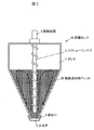
図1は、本発明の実施の形態に係る貯蔵タンクの使用時の状態を示す概略断面図である。以下、図1を参照して本発明の実施の形態に係る貯蔵タンクを説明する。 FIG. 1 is a schematic cross-sectional view showing a state in use of a storage tank according to an embodiment of the present invention. Hereinafter, a storage tank according to an embodiment of the present invention will be described with reference to FIG.
本発明の実施の形態に係る貯蔵タンク10は、タンク1内の貯蔵物(樹脂混和物ペレット20)を下方から上方に向けて搬送する搬送装置(スクリューコンベア2及び駆動装置3)を備える。 The storage tank 10 according to the embodiment of the present invention includes a transport device (a screw conveyor 2 and a drive device 3) that transports a stored product (resin admixture pellet 20) in the tank 1 from below to above.
タンク1は、側壁の上部又は上壁に、図示していない貯蔵物搬入口を有する。また、タンク1の下部は、ホッパー形状(逆三角形状、漏斗形状)であり、その先端に貯蔵物が排出される排出口4が形成されている。貯蔵(保管)中は、排出口4は排出弁5により塞がれており、貯蔵物が排出されないようにされている。 The tank 1 has a storage port (not shown) on the upper or upper wall of the side wall. Moreover, the lower part of the tank 1 is a hopper shape (inverted triangle shape, funnel shape), and the discharge port 4 from which the stored matter is discharged is formed in the front-end | tip. During storage (storage), the discharge port 4 is closed by the discharge valve 5 so that the stored product is not discharged.
タンク1内に貯蔵される貯蔵物としては、特に限定されるものではないが、樹脂混和物からなるペレット(樹脂混和物ペレット20)などの接着し易い材料からなるペレット等が特に好適である。 The stored material stored in the tank 1 is not particularly limited, but a pellet made of a material that is easily bonded, such as a pellet made of a resin mixture (resin mixture pellet 20), is particularly suitable.
樹脂混和物ペレット20は、例えば、電線被覆材用のペレットである。また、樹脂混和物は、例えば、ポリオレフィン樹脂混和物である。 The resin mixture pellet 20 is, for example, a pellet for a wire coating material. The resin blend is, for example, a polyolefin resin blend.
貯蔵物は、上記の樹脂混和物ペレットに限られず、パウダー状の樹脂混和物や、樹脂混和物の原料である、ペレット状もしくはパウダー状の樹脂、難燃剤、充填剤、安定剤、酸化防止剤などであってもよい。 Stored products are not limited to the above resin admixture pellets, but are powdered resin admixtures, pellet-form or powder-form resins, flame retardants, fillers, stabilizers, antioxidants that are the raw materials for resin admixtures. It may be.
搬送装置は、樹脂混和物ペレット20をタンク1の下方から上方に向けて搬送できる装置であればよく、例えば、図1に示すスクリューコンベア2と、スクリューコンベア2を駆動する駆動装置3とから構成される。樹脂混和物ペレット20を効率よく下方から上方に向けて搬送することが可能となる点で、スクリューコンベア2を用いることが好ましい。 The conveying device may be any device that can convey the resin admixture pellet 20 from the lower side to the upper side of the tank 1, and includes, for example, a screw conveyor 2 shown in FIG. 1 and a driving device 3 that drives the screw conveyor 2. Is done. It is preferable to use the screw conveyor 2 in that the resin admixture pellet 20 can be efficiently conveyed from below to above.
スクリューコンベア2は、例えば、図1に示すように、貯蔵タンク10の中央部に鉛直に設けられる。 For example, as shown in FIG. 1, the screw conveyor 2 is provided vertically at the center of the storage tank 10.
また、スクリューコンベア2は、単軸に限らず、多軸のスクリューコンベアを用いることもできる。 Further, the screw conveyor 2 is not limited to a single axis, and a multi-axis screw conveyor can also be used.
スクリューコンベア2を駆動させると、タンク1内部の下方にある樹脂混和物ペレット20が上方へ搬送されることで生じる空隙に周囲の樹脂混和物ペレット20が自重により移動し、タンク1内の樹脂混和物ペレット20全体が流動することでペレット同士が接着し合って出来るブロックの形成を防止できる。これにより、樹脂混和物ペレット20をタンク1内に貯蔵しても、ブロックを形成することなく、長時間、タンク1内で保管することが出来る。 When the screw conveyor 2 is driven, the resin admixture pellets 20 in the tank 1 are moved by their own weight into the gap generated when the resin admixture pellets 20 below the tank 1 are conveyed upward, and the resin admixture in the tank 1 is mixed. The formation of the block which the pellets adhere | attach and can be prevented because the whole thing pellet 20 flows can be prevented. Thereby, even if the resin mixture pellet 20 is stored in the tank 1, it can be stored in the tank 1 for a long time without forming a block.
なお、本発明は、上記実施の形態に限定されず種々に変形実施が可能である。 In addition, this invention is not limited to the said embodiment, A various deformation | transformation implementation is possible.
1:タンク、2:スクリューコンベア、3:駆動装置、4:排出口、5:排出弁
10:貯蔵タンク、20:樹脂混和物ペレット
1: tank, 2: screw conveyor, 3: drive device, 4: discharge port, 5: discharge valve, 10: storage tank, 20: resin admixture pellet
Claims (7)
Priority Applications (1)
| Application Number | Priority Date | Filing Date | Title |
|---|---|---|---|
| JP2015081220A JP2016199295A (en) | 2015-04-10 | 2015-04-10 | Storage tank |
Applications Claiming Priority (1)
| Application Number | Priority Date | Filing Date | Title |
|---|---|---|---|
| JP2015081220A JP2016199295A (en) | 2015-04-10 | 2015-04-10 | Storage tank |
Publications (1)
| Publication Number | Publication Date |
|---|---|
| JP2016199295A true JP2016199295A (en) | 2016-12-01 |
Family
ID=57423908
Family Applications (1)
| Application Number | Title | Priority Date | Filing Date |
|---|---|---|---|
| JP2015081220A Pending JP2016199295A (en) | 2015-04-10 | 2015-04-10 | Storage tank |
Country Status (1)
| Country | Link |
|---|---|
| JP (1) | JP2016199295A (en) |
Cited By (1)
| Publication number | Priority date | Publication date | Assignee | Title |
|---|---|---|---|---|
| CN107263907A (en) * | 2017-07-19 | 2017-10-20 | 望谟县布依王油脂有限公司 | A kind of rapeseed oil is cold rolling to use lag cooler |
-
2015
- 2015-04-10 JP JP2015081220A patent/JP2016199295A/en active Pending
Cited By (1)
| Publication number | Priority date | Publication date | Assignee | Title |
|---|---|---|---|---|
| CN107263907A (en) * | 2017-07-19 | 2017-10-20 | 望谟县布依王油脂有限公司 | A kind of rapeseed oil is cold rolling to use lag cooler |
Similar Documents
| Publication | Publication Date | Title |
|---|---|---|
| AR036957A1 (en) | PULVERULENT MATTER REPAIR SYSTEM WITH CONTROLLED PONDERAL FLOWS | |
| JP2016199295A (en) | Storage tank | |
| JP4984036B2 (en) | Feed production apparatus and feed production method | |
| CN202465280U (en) | Carbon material homogenizing and mixing equipment | |
| CN107835732B (en) | The manufacturing method of resin combination | |
| CN205526784U (en) | Bilateral unloader of powder for chemical production | |
| CN205555574U (en) | Silo with function of unloading | |
| CN208177408U (en) | A kind of granulating mechanism of rotating pelletizer | |
| MY189702A (en) | Raw material storage hopper | |
| CN104369882B (en) | A kind of particles packing machine | |
| JP5181387B2 (en) | Powder / particle supply coupler, powder / particle supply mechanism using the same, and particle / particle supply system including the mechanism | |
| CN206463907U (en) | Blending Fertilizer measures deployment device | |
| CN210312581U (en) | Plastic particle conveying device | |
| US20230234264A1 (en) | Device and method for processing bulk material | |
| WO1981002565A1 (en) | Means for conveying a mixture of products having different density | |
| JP2004195336A (en) | Method and apparatus for mixing granular substance | |
| CN203781205U (en) | Scraper conveyor | |
| CN212475270U (en) | Production of textile adhesive is with throwing material mechanism | |
| CN202807915U (en) | Powder conveyer device | |
| CN207535312U (en) | A kind of 3D printer nozzle | |
| CN205635346U (en) | Glass raw materials processing apparatus | |
| CN107539504A (en) | Pitch Geldart-D particle batching weighing system | |
| CN105617921A (en) | Feed additive batching device | |
| CN105639695B (en) | Premixed feed processing technology | |
| Bradley | Flow of bulk solids; sixty years of progress (?) and where has it got us? |
Legal Events
| Date | Code | Title | Description |
|---|---|---|---|
| RD04 | Notification of resignation of power of attorney |
Free format text: JAPANESE INTERMEDIATE CODE: A7424 Effective date: 20180327 |